US10126559B2 - System for spatial recombination of ultrashort laser pulses by means of a diffractive element - Google Patents
System for spatial recombination of ultrashort laser pulses by means of a diffractive element Download PDFInfo
- Publication number
- US10126559B2 US10126559B2 US15/313,028 US201515313028A US10126559B2 US 10126559 B2 US10126559 B2 US 10126559B2 US 201515313028 A US201515313028 A US 201515313028A US 10126559 B2 US10126559 B2 US 10126559B2
- Authority
- US
- United States
- Prior art keywords
- diffractive optical
- spatial
- recombining
- compensating
- optical element
- Prior art date
- Legal status (The legal status is an assumption and is not a legal conclusion. Google has not performed a legal analysis and makes no representation as to the accuracy of the status listed.)
- Active
Links
- 230000006798 recombination Effects 0.000 title abstract description 6
- 238000005215 recombination Methods 0.000 title abstract description 6
- 230000003287 optical effect Effects 0.000 claims abstract description 47
- 230000000737 periodic effect Effects 0.000 claims description 9
- 229920000535 Tan II Polymers 0.000 claims description 4
- 230000001747 exhibiting effect Effects 0.000 claims description 3
- 230000001360 synchronised effect Effects 0.000 claims description 3
- 238000003384 imaging method Methods 0.000 abstract description 8
- 238000011144 upstream manufacturing Methods 0.000 abstract description 3
- 239000006185 dispersion Substances 0.000 description 12
- 238000009826 distribution Methods 0.000 description 10
- 230000001427 coherent effect Effects 0.000 description 8
- 239000013598 vector Substances 0.000 description 8
- 230000007547 defect Effects 0.000 description 7
- 238000000034 method Methods 0.000 description 6
- 230000000694 effects Effects 0.000 description 4
- 238000005457 optimization Methods 0.000 description 4
- 210000001747 pupil Anatomy 0.000 description 4
- 230000003595 spectral effect Effects 0.000 description 4
- 230000005540 biological transmission Effects 0.000 description 2
- 238000010276 construction Methods 0.000 description 2
- 230000001066 destructive effect Effects 0.000 description 2
- 238000001228 spectrum Methods 0.000 description 2
- 230000007423 decrease Effects 0.000 description 1
- 230000000593 degrading effect Effects 0.000 description 1
- 230000001627 detrimental effect Effects 0.000 description 1
- 230000005672 electromagnetic field Effects 0.000 description 1
- 238000004519 manufacturing process Methods 0.000 description 1
- 230000010287 polarization Effects 0.000 description 1
- 238000000926 separation method Methods 0.000 description 1
Images




Classifications
-
- H—ELECTRICITY
- H01—ELECTRIC ELEMENTS
- H01S—DEVICES USING THE PROCESS OF LIGHT AMPLIFICATION BY STIMULATED EMISSION OF RADIATION [LASER] TO AMPLIFY OR GENERATE LIGHT; DEVICES USING STIMULATED EMISSION OF ELECTROMAGNETIC RADIATION IN WAVE RANGES OTHER THAN OPTICAL
- H01S3/00—Lasers, i.e. devices using stimulated emission of electromagnetic radiation in the infrared, visible or ultraviolet wave range
- H01S3/23—Arrangements of two or more lasers not provided for in groups H01S3/02 - H01S3/22, e.g. tandem arrangements of separate active media
-
- G—PHYSICS
- G02—OPTICS
- G02B—OPTICAL ELEMENTS, SYSTEMS OR APPARATUS
- G02B27/00—Optical systems or apparatus not provided for by any of the groups G02B1/00 - G02B26/00, G02B30/00
- G02B27/10—Beam splitting or combining systems
- G02B27/1086—Beam splitting or combining systems operating by diffraction only
-
- H—ELECTRICITY
- H01—ELECTRIC ELEMENTS
- H01S—DEVICES USING THE PROCESS OF LIGHT AMPLIFICATION BY STIMULATED EMISSION OF RADIATION [LASER] TO AMPLIFY OR GENERATE LIGHT; DEVICES USING STIMULATED EMISSION OF ELECTROMAGNETIC RADIATION IN WAVE RANGES OTHER THAN OPTICAL
- H01S3/00—Lasers, i.e. devices using stimulated emission of electromagnetic radiation in the infrared, visible or ultraviolet wave range
- H01S3/005—Optical devices external to the laser cavity, specially adapted for lasers, e.g. for homogenisation of the beam or for manipulating laser pulses, e.g. pulse shaping
-
- H—ELECTRICITY
- H01—ELECTRIC ELEMENTS
- H01S—DEVICES USING THE PROCESS OF LIGHT AMPLIFICATION BY STIMULATED EMISSION OF RADIATION [LASER] TO AMPLIFY OR GENERATE LIGHT; DEVICES USING STIMULATED EMISSION OF ELECTROMAGNETIC RADIATION IN WAVE RANGES OTHER THAN OPTICAL
- H01S3/00—Lasers, i.e. devices using stimulated emission of electromagnetic radiation in the infrared, visible or ultraviolet wave range
- H01S3/05—Construction or shape of optical resonators; Accommodation of active medium therein; Shape of active medium
- H01S3/08—Construction or shape of optical resonators or components thereof
- H01S3/08004—Construction or shape of optical resonators or components thereof incorporating a dispersive element, e.g. a prism for wavelength selection
- H01S3/08009—Construction or shape of optical resonators or components thereof incorporating a dispersive element, e.g. a prism for wavelength selection using a diffraction grating
-
- H—ELECTRICITY
- H01—ELECTRIC ELEMENTS
- H01S—DEVICES USING THE PROCESS OF LIGHT AMPLIFICATION BY STIMULATED EMISSION OF RADIATION [LASER] TO AMPLIFY OR GENERATE LIGHT; DEVICES USING STIMULATED EMISSION OF ELECTROMAGNETIC RADIATION IN WAVE RANGES OTHER THAN OPTICAL
- H01S3/00—Lasers, i.e. devices using stimulated emission of electromagnetic radiation in the infrared, visible or ultraviolet wave range
- H01S3/10—Controlling the intensity, frequency, phase, polarisation or direction of the emitted radiation, e.g. switching, gating, modulating or demodulating
-
- H—ELECTRICITY
- H01—ELECTRIC ELEMENTS
- H01S—DEVICES USING THE PROCESS OF LIGHT AMPLIFICATION BY STIMULATED EMISSION OF RADIATION [LASER] TO AMPLIFY OR GENERATE LIGHT; DEVICES USING STIMULATED EMISSION OF ELECTROMAGNETIC RADIATION IN WAVE RANGES OTHER THAN OPTICAL
- H01S3/00—Lasers, i.e. devices using stimulated emission of electromagnetic radiation in the infrared, visible or ultraviolet wave range
- H01S3/23—Arrangements of two or more lasers not provided for in groups H01S3/02 - H01S3/22, e.g. tandem arrangements of separate active media
- H01S3/2383—Parallel arrangements
-
- H—ELECTRICITY
- H01—ELECTRIC ELEMENTS
- H01S—DEVICES USING THE PROCESS OF LIGHT AMPLIFICATION BY STIMULATED EMISSION OF RADIATION [LASER] TO AMPLIFY OR GENERATE LIGHT; DEVICES USING STIMULATED EMISSION OF ELECTROMAGNETIC RADIATION IN WAVE RANGES OTHER THAN OPTICAL
- H01S3/00—Lasers, i.e. devices using stimulated emission of electromagnetic radiation in the infrared, visible or ultraviolet wave range
- H01S3/05—Construction or shape of optical resonators; Accommodation of active medium therein; Shape of active medium
- H01S3/08—Construction or shape of optical resonators or components thereof
- H01S3/081—Construction or shape of optical resonators or components thereof comprising three or more reflectors
- H01S3/082—Construction or shape of optical resonators or components thereof comprising three or more reflectors defining a plurality of resonators, e.g. for mode selection or suppression
- H01S3/0823—Construction or shape of optical resonators or components thereof comprising three or more reflectors defining a plurality of resonators, e.g. for mode selection or suppression incorporating a dispersive element, e.g. a prism for wavelength selection
- H01S3/0826—Construction or shape of optical resonators or components thereof comprising three or more reflectors defining a plurality of resonators, e.g. for mode selection or suppression incorporating a dispersive element, e.g. a prism for wavelength selection using a diffraction grating
Definitions
- the field of the invention is that of the coherent recombining of a large number of ultra-short pulse laser sources, that is to say with pulse width of less than a picosecond.
- the framework of the invention relates to the technique of the spatial recombining of these laser pulses, assumed to be perfectly synchronized otherwise.
- Coherent recombination of ultra-short pulse laser sources applies notably to the realization of high-energy laser sources.
- Methods for spatially recombining coherent beams fall into 2 categories, depending on whether one chooses to juxtapose the optical beams in the far field or to superpose them in the near field, that is to say at the level of the exit pupil of the system.
- FIG. 1 a A system for recombining by juxtaposition is shown in FIG. 1 a .
- the beams to be recombined arising from laser sources F k , k varying from 0 to N, are parallel and collimated in the near field by an array of collimating lenses MLC, and are disposed alongside one another, in the most compact manner possible.
- the superposition of the beams is then performed by free propagation up to the far field.
- Such a system does not involve any dispersive hardware components and therefore applies equally for pulse widths of less than a picosecond.
- the major drawback of this system is its relatively low efficiency, with notably an appreciable share of the energy lost in the grating lobes.
- the optical beams arising from the laser sources F k and collimated by collimating lenses CL k are superposed in the near field by means of polarization-splitter cubes PBS k respectively associated with half-wave plates HWP k , as illustrated by the example of FIG. 1 b .
- the recombining efficiency for N beams is given by:
- none of these systems is suitable for recombining a large number of pulses (typically >100 or indeed 1000), i.e. due to problems of efficiency (grating lobes for the far-field device), or of implementation for near-field systems.
- a diffractive optical element to combine the beams.
- a lens 23 in a Fourier-transform setup makes it possible to collimate the beams to be recombined (arising from the laser sources F k ) and to direct them toward a diffractive optical element or DOE 1 situated in the focal plane of the lens 23 .
- the spatial distribution of the source points in the object plane A of the lens 23 (periodic distribution of period P A ) is transformed into a distribution of angles of incidence on the optical element DOE 1 .
- the optical element 1 is typically a periodic phase grating, for example of Damann grating type, which ensures the constructive interference of all the incident beams on the order 0 , and destructive on all the other orders; the period ⁇ of this grating and the angles of incidence ⁇ 2k are related by the known formula for diffraction gratings:
- this architecture notably a high efficiency (beyond 90% demonstrated in the continuous regime), and an architecture that is well suited to a very large number of beams (typically >100) on account of this collective positioning, of a possible two-dimensional arrangement, and of the use of a single lens.
- this technique may not apply as is in the ultra-short pulse regime.
- the technical problem to be solved consists in transferring as efficiently as possible the energy of each of the laser pulses to a single pulse by a coherent process, while degrading the beam quality of the final pulse as little as possible with respect to the elementary pulses, while being compatible with a large number of summed pulses, and also sub-picosecond pulse duration.
- the proposed solution is based on recombination by superposition using a diffractive optical element DOE to combine the beams.
- an optical diffractive assembly is placed upstream of this diffractive optical element so as to make it possible, via an appropriate imaging system, to optimize the combining efficiency in the ultra-short pulse regime.
- the subject of the invention is a system for the spatial recombining of pulse laser beams of the same wavelength centered around ⁇ 0 , arising from N synchronized sources k, k varying from 1 to N, N being an integer >1, which has an optical axis and comprises:
- a recombining diffractive optical element with periodic phase profile on which the N beams are intended to be directed by the Fourier lens according to an angle of incidence ⁇ 2k that differs from one beam to the next, these angles of incidence being determined as a function of the period of the recombining diffractive optical element.
- the sources are able to emit pulses of duration of less than 10 ⁇ 12 s, and in that it comprises:
- N compensating diffractive optical elements with periodic grating with one compensating diffractive optical element per source, an angle of incidence ⁇ 1k that differs from one beam to the next, and a grating spacing ⁇ 1k that differs between neighboring compensating diffractive optical elements
- the angle of incidence ⁇ 1k of the beam on the compensating DOE, the angle of inclination ⁇ k of the compensating DOE on the optical axis, and the spacing ⁇ 1k of its grating are determined on the basis of the spacing P A , of k, of ⁇ 0 , of the magnification ⁇ , of the focal length f 2 and of the period of the recombining diffractive optical element.
- the angles of inclination ⁇ k of the compensating DOEs are zero, the DOEs being situated in one and the same plane.
- the sources can be disposed according to a one-dimensional or two-dimensional spatial configuration.
- the compensating DOE gratings are blazed gratings.
- the beams arising from the laser sources have one and the same exit plane
- the system comprises another Fourier lens having an object plane in which the exit plane of the laser sources and an image plane of the laser sources is situated.
- the position of the image plane of this lens with respect to the plane in which the assembly of the compensating diffractive optical elements is situated, as well as the separation of the sources in the object plane of the lens, are determined as a function of the focal length of the Fourier lens, of the period P A , and of the angles ⁇ 1k .
- FIG. 1 a -l c already described schematically represent systems for the spatial recombining of coherent beams in the near field ( FIG. 1 a ), in the far field ( FIG. 1 b ) and by a diffractive element ( FIG. 1 c ),
- FIGS. 2 a -2 c schematically illustrate the problems posed by a system for the spatial recombining of coherent beams by a diffractive element: the chromatic dispersion ( FIG. 2 a ), the defect of spatial overlap ( FIG. 2 b ), as well as an exemplary curve of the overlap coefficient as a function of the size of the pupil ( FIG. 2 c ),
- FIG. 3 schematically illustrates the conditions fulfilled by a system for the spatial recombining of coherent beams by a diffractive element according to the invention
- FIG. 4 schematically represents an exemplary system for the spatial recombining of coherent beams by a diffractive element according to the invention
- FIGS. 5 a -5 c schematically represent for a single source, the principle ( FIG. 5 a ) of chromatic dispersion compensation and of optimization of the spatial overlap by a system for the spatial recombining of beams according to the invention, a more detailed view at the level of a compensating DOE illustrating the inclination of the spatial distribution of the pulse on passing through a compensating DOE ( FIG. 5 b ), and the corresponding geometric construction illustrating the geometric construction of the grating vector ⁇ right arrow over (K) ⁇ k,1 of the compensating DOE as a function of the angles of incidence and of inclination of the grating, and of the incident wave vector ⁇ right arrow over (K) ⁇ i,1 ( FIG. 5 c ),
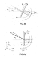
- FIGS. 6 a and 6 b schematically illustrate the graphical determination of the angles of diffraction on a compensating DOE ( FIG. 6 a ) and on the combining DOE ( FIG. 6 b ) for two different wavelengths
- FIG. 7 illustrates an exemplary calculation of the angles of incidence and of inclination of the compensation gratings for optimization of the overlap of the pulses on the combining DOE and compensation of the chromatic dispersion
- FIGS. 8 a and 8 b show two exemplary embodiments of a system for the spatial recombining of beams according to the invention, with compensating DOEs disposed in one and the same plane when the chromatic compensation ( FIG. 8 b ) or the compensation of the overlap defect ( FIG. 8 a ) is favored.
- FIG. 9 shows a third exemplary embodiment of a system for the spatial recombining of beams according to the invention, with another Fourier lens.
- a recombining system using an optical diffractive element DOE which ensures the constructive interference of all the pulses along a single direction of propagation, and destructive along all others, could be an excellent candidate for recombining a large number of pulses, but it suffers from two major problems in the ultra-short pulse regime:
- the defect of spatial overlap of the pulses at the level of the DOE on account of the distribution of the angles of incidence of the beams.
- the system according to the invention comprises a compensating configuration, the technical effect of which is to realize the conditions illustrated in FIG. 3 , that is to say:
- the red and blue components of the spectrum of the pulse must arrive with different angles of incidence on the combining DOE 1 , calculated in such a way that the wave vectors on exiting this combining DOE are all along the z axis of the figure, whatever the wavelength;
- the spatial distribution of energy at a set instant must be parallel to the combining DOE 1 , i.e. parallel to the yOx plane of the figure, this being so as to optimize the spatial overlap of the pulses on the combining DOE.
- This compensating configuration 2 is described in conjunction with FIGS. 4 and 5 a , 5 b and 5 c.
- a first diffractive compensating assembly 21 is imaged on the combining DOE 1 by an imaging device.
- This imaging device comprises:
- This array 22 of lenses forms with the Fourier lens 23 a double-FT setup of predetermined magnification ⁇ , able to image the diffractive optical compensating assembly 21 on the recombining diffractive optical element 1 : the diffractive optical compensating assembly 21 is situated in the object plane of the array of lenses 22 , the recombining DOE 1 being situated in the image plane of the Fourier lens 23 , the image plane of the array of lenses 22 coinciding with the object plane of the Fourier lens 23 .
- This diffractive compensating assembly 21 is subdivided into N compensating DOEs also spaced apart by P A , each compensating DOE 211 comprising a periodic phase and/or amplitude grating of spacing ⁇ 1k .
- the optical beams arising from the pulse laser sources S k are collimated upstream of the system (they are for example situated in a plane and collimated by a lens, or positioned directly according to their angle of incidence ⁇ 1k with a collimating lens associated with each source), and each beam arrives with a specific angle ⁇ 1k on the corresponding compensating DOE 211 .
- the middles of these DOEs 211 are situated on one and the same plane situated at f 1 of the array 22 of lenses.
- angles ⁇ 2k are also related to the period of the grating of the combining DOE 1 so as to obtain the desired optimal combining.
- the angle of inclination (in the plane xOz) of the energy distribution of the pulses before the lens 23 must equal ⁇ 2k .
- each compensating DOE 211 comprises a grating of uniform spacing ⁇ k , and that its normal is inclined by an angle ⁇ k with respect to the desired direction of propagation on exiting the DOE 211 (z axis in FIGS. 5 a , 5 b , 5 c ).
- the angle between the direction of incidence of the source S k and the desired direction of propagation on exit from the DOE is designated by ⁇ 1k .
- ⁇ 1k designates the angle on exit from the compensating DOE 211 , between the spatial distribution of energy of the pulse and the axis of propagation of the pulse.
- tan ⁇ ( ⁇ 1 ⁇ k ) sin ⁇ ⁇ ( ⁇ 1 ⁇ k - ⁇ 1 ⁇ k ) cos ⁇ ( ⁇ 1 ⁇ k ) + tan ⁇ ⁇ ( ⁇ 1 ⁇ k )
- the spacing ⁇ 1k of its grating is established as a function of the direction of incidence ⁇ 1k , of the direction of inclination of the grating, and of the wavelength ⁇ 0 by:
- ⁇ 1 ⁇ k ⁇ 0 sin ⁇ ( ⁇ 1 ⁇ k - ⁇ k ) + sin ⁇ ( ⁇ k )
- the combining DOE is considered to be the superposition of N sinusoidal gratings (N being the number of beams to be combined), of spacing ⁇ 2k given by:
- the period of the grating of the combining DOE is therefore equal to: ⁇ 0 /sin ⁇ 21 .
- the chromatic dispersion of the combining DOE 1 is therefore equal to:
- the spacing of the compensation grating ⁇ 1k is established as a function of the direction of incidence ⁇ 1k , of the direction of inclination of the grating, and of the wavelength ⁇ 0 by:
- ⁇ 1 ⁇ k ⁇ 0 sin ⁇ ( ⁇ 1 ⁇ k - ⁇ k ) + sin ⁇ ( ⁇ k )
- ⁇ 1 ⁇ k ⁇ ⁇ 0 ⁇ ( tan ⁇ ( ⁇ k ) + sin ⁇ ( ⁇ 1 ⁇ k ) cos ⁇ ⁇ ⁇ k )
- the angular dispersion of the compensating DOE 211 is therefore equal to:
- the chromatic compensation condition is deduced from the calculation of the angular magnification of the off-centered imaging device of transverse magnification ⁇ such as that of the system described in FIG. 5 a .
- the following condition is therefore obtained:
- FIG. 7 represents the values of angle of incidence ⁇ 1k ⁇ k on the compensating DOEs and the angles of inclination ⁇ k of the compensating DOEs 211 , which satisfy the above system, and therefore ensure simultaneous compensation of the effects of chromatic dispersion of the combining DOE 1 and the defect of spatial overlap of the pulses on the combining DOE.
- the compensating DOEs 211 are situated on one and the same plane, thereby simplifying the system and avoiding notably devices for orienting each DOE 211 which are bulky and increase the cost of the overall system.
- the angle of incidence ⁇ 1k of the beam is such that:
- the gratings of the compensating DOEs are advantageously blazed phase gratings.
- they may be phase gratings with sinusoidal continuous profile, with binary profile, or intensity gratings with binary profile (black and white) or ne gray levels. All these examples, except blazed gratings, exhibit multiple diffraction orders and therefore penalize the overall efficiency of the system.
- the combining DOE 1 and compensating DOE 211 operate in transmission; the principle of the system according to the invention remains valid when using DOEs in reflection.
Landscapes
- Physics & Mathematics (AREA)
- Electromagnetism (AREA)
- Optics & Photonics (AREA)
- Engineering & Computer Science (AREA)
- Plasma & Fusion (AREA)
- General Physics & Mathematics (AREA)
- Diffracting Gratings Or Hologram Optical Elements (AREA)
- Lasers (AREA)
Applications Claiming Priority (3)
| Application Number | Priority Date | Filing Date | Title |
|---|---|---|---|
| FR1401219A FR3021760B1 (fr) | 2014-05-28 | 2014-05-28 | Systeme de recombinaison spatiale d'impulsions laser ultra-breves par un element diffractif |
| FR1401219 | 2014-05-28 | ||
| PCT/EP2015/061536 WO2015181137A1 (fr) | 2014-05-28 | 2015-05-26 | Systeme de recombinaison spatiale d'impulsions laser ultra-breves par un element diffractif |
Publications (2)
| Publication Number | Publication Date |
|---|---|
| US20170199390A1 US20170199390A1 (en) | 2017-07-13 |
| US10126559B2 true US10126559B2 (en) | 2018-11-13 |
Family
ID=51610151
Family Applications (1)
| Application Number | Title | Priority Date | Filing Date |
|---|---|---|---|
| US15/313,028 Active US10126559B2 (en) | 2014-05-28 | 2015-05-26 | System for spatial recombination of ultrashort laser pulses by means of a diffractive element |
Country Status (11)
| Country | Link |
|---|---|
| US (1) | US10126559B2 (fr) |
| EP (1) | EP3149524B1 (fr) |
| JP (1) | JP6577492B2 (fr) |
| KR (1) | KR102342129B1 (fr) |
| CN (1) | CN106662752B (fr) |
| DK (1) | DK3149524T3 (fr) |
| FR (1) | FR3021760B1 (fr) |
| HU (1) | HUE054668T2 (fr) |
| IL (1) | IL249157B (fr) |
| LT (1) | LT3149524T (fr) |
| WO (1) | WO2015181137A1 (fr) |
Families Citing this family (3)
| Publication number | Priority date | Publication date | Assignee | Title |
|---|---|---|---|---|
| US10444526B2 (en) * | 2016-08-01 | 2019-10-15 | The Regents Of The University Of California | Optical pulse combiner comprising diffractive optical elements |
| CN109346849B (zh) * | 2018-09-06 | 2021-01-08 | 中国科学院国家空间科学中心 | 一种产生毫米波贝塞尔波束的装置 |
| CN112558314B (zh) * | 2020-12-01 | 2022-10-25 | 中国空间技术研究院 | 激光阵列分束器和光栅设计方法 |
Citations (5)
| Publication number | Priority date | Publication date | Assignee | Title |
|---|---|---|---|---|
| US6570896B2 (en) * | 1999-10-07 | 2003-05-27 | Deutsches Zentrum Fuer Luft-Und Raumfahrt E.V. | Laser radiation source and process for generating a coherent total laser radiation field |
| DE102010033630A1 (de) | 2009-08-07 | 2011-02-10 | Northrop Grumman Systems Corporation, Los Angeles | Hochleistungs-Faserverstärker mit integrierter kohärenter Zusammenführung aller Faserstrahlen |
| US7924894B2 (en) * | 2008-01-18 | 2011-04-12 | Northrop Grumman Systems Corporation | Digital piston error control for high-power laser system employing diffractive optical element beam combiner |
| US20110305250A1 (en) * | 2010-03-05 | 2011-12-15 | TeraDiode, Inc. | Wavelength beam combining based pulsed lasers |
| US8179594B1 (en) | 2007-06-29 | 2012-05-15 | Lockheed Martin Corporation | Method and apparatus for spectral-beam combining of fanned-in laser beams with chromatic-dispersion compensation using a plurality of diffractive gratings |
-
2014
- 2014-05-28 FR FR1401219A patent/FR3021760B1/fr active Active
-
2015
- 2015-05-26 WO PCT/EP2015/061536 patent/WO2015181137A1/fr not_active Ceased
- 2015-05-26 CN CN201580040988.7A patent/CN106662752B/zh active Active
- 2015-05-26 KR KR1020167036622A patent/KR102342129B1/ko active Active
- 2015-05-26 LT LTEP15725589.4T patent/LT3149524T/lt unknown
- 2015-05-26 US US15/313,028 patent/US10126559B2/en active Active
- 2015-05-26 DK DK15725589.4T patent/DK3149524T3/da active
- 2015-05-26 EP EP15725589.4A patent/EP3149524B1/fr active Active
- 2015-05-26 JP JP2016569836A patent/JP6577492B2/ja active Active
- 2015-05-26 HU HUE15725589A patent/HUE054668T2/hu unknown
-
2016
- 2016-11-23 IL IL249157A patent/IL249157B/en active IP Right Grant
Patent Citations (5)
| Publication number | Priority date | Publication date | Assignee | Title |
|---|---|---|---|---|
| US6570896B2 (en) * | 1999-10-07 | 2003-05-27 | Deutsches Zentrum Fuer Luft-Und Raumfahrt E.V. | Laser radiation source and process for generating a coherent total laser radiation field |
| US8179594B1 (en) | 2007-06-29 | 2012-05-15 | Lockheed Martin Corporation | Method and apparatus for spectral-beam combining of fanned-in laser beams with chromatic-dispersion compensation using a plurality of diffractive gratings |
| US7924894B2 (en) * | 2008-01-18 | 2011-04-12 | Northrop Grumman Systems Corporation | Digital piston error control for high-power laser system employing diffractive optical element beam combiner |
| DE102010033630A1 (de) | 2009-08-07 | 2011-02-10 | Northrop Grumman Systems Corporation, Los Angeles | Hochleistungs-Faserverstärker mit integrierter kohärenter Zusammenführung aller Faserstrahlen |
| US20110305250A1 (en) * | 2010-03-05 | 2011-12-15 | TeraDiode, Inc. | Wavelength beam combining based pulsed lasers |
Also Published As
| Publication number | Publication date |
|---|---|
| LT3149524T (lt) | 2021-06-25 |
| KR20170012446A (ko) | 2017-02-02 |
| HUE054668T2 (hu) | 2021-09-28 |
| EP3149524B1 (fr) | 2021-02-17 |
| DK3149524T3 (da) | 2021-05-03 |
| KR102342129B1 (ko) | 2021-12-21 |
| EP3149524A1 (fr) | 2017-04-05 |
| FR3021760B1 (fr) | 2016-07-01 |
| JP2017518642A (ja) | 2017-07-06 |
| CN106662752B (zh) | 2019-05-21 |
| IL249157A0 (en) | 2017-01-31 |
| JP6577492B2 (ja) | 2019-09-18 |
| FR3021760A1 (fr) | 2015-12-04 |
| WO2015181137A1 (fr) | 2015-12-03 |
| CN106662752A (zh) | 2017-05-10 |
| IL249157B (en) | 2020-10-29 |
| US20170199390A1 (en) | 2017-07-13 |
Similar Documents
| Publication | Publication Date | Title |
|---|---|---|
| US7948680B2 (en) | Spectral beam combination using broad bandwidth lasers | |
| DE102019118010B4 (de) | Strukturierter lichtprojektor und verfahren zum herstellen eines solchen | |
| CN111190246B (zh) | 光学系统中像差校正的系统的方法 | |
| JP2013521667A (ja) | 選択的再配置および回転波長ビーム結合システムならびに方法 | |
| US9759924B2 (en) | Flat profile laser beam shaper | |
| JP2004536350A (ja) | 空間的に部分的にコヒーレントな光ビームの強度分布の回折成形 | |
| US10983262B2 (en) | Rotational geometric phase hologram with application for fabricating geometric phase optical element | |
| US10126559B2 (en) | System for spatial recombination of ultrashort laser pulses by means of a diffractive element | |
| CN102841451A (zh) | 一种用环形组合半波片生成矢量光束的装置 | |
| US20070217740A1 (en) | Method and apparatus for optimizing the target intensity distribution transmitted from a fiber coupled array | |
| US7548375B2 (en) | Method and device for influencing light | |
| TWI485431B (zh) | 用於均質同調輻射的設備 | |
| Kamali et al. | Dielectric metasurfaces with independent angular control | |
| Pala et al. | Application of holographic diffractive doublets as collimators for highly elliptical light beams edge emitted from diode lasers | |
| CN114813050A (zh) | 一种多模蓝光单管激光模式测量装置 | |
| Liu et al. | Optical Design and Beam Shaping in High Power Semiconductor Lasers | |
| Sales | Uniform and efficient illumination with saddle lenses | |
| Vyas et al. | Exotic vortex beam shapes for optical traps | |
| AU2002210034A1 (en) | Diffractive shaping of the intensity distribution of a spatially partially coherent light beam | |
| JP2016035548A (ja) | 回折パターン投影光学系 |
Legal Events
| Date | Code | Title | Description |
|---|---|---|---|
| AS | Assignment |
Owner name: THALES, FRANCE Free format text: ASSIGNMENT OF ASSIGNORS INTEREST;ASSIGNORS:BOURDERIONNET, JEROME;BRIGNON, ARNAUD;REEL/FRAME:040937/0919 Effective date: 20170109 |
|
| STCF | Information on status: patent grant |
Free format text: PATENTED CASE |
|
| MAFP | Maintenance fee payment |
Free format text: PAYMENT OF MAINTENANCE FEE, 4TH YEAR, LARGE ENTITY (ORIGINAL EVENT CODE: M1551); ENTITY STATUS OF PATENT OWNER: LARGE ENTITY Year of fee payment: 4 |