US10160482B2 - Driving support control apparatus using electric power steering mechanism - Google Patents
Driving support control apparatus using electric power steering mechanism Download PDFInfo
- Publication number
- US10160482B2 US10160482B2 US15/544,978 US201615544978A US10160482B2 US 10160482 B2 US10160482 B2 US 10160482B2 US 201615544978 A US201615544978 A US 201615544978A US 10160482 B2 US10160482 B2 US 10160482B2
- Authority
- US
- United States
- Prior art keywords
- disturbance
- characteristic
- electric power
- torque
- control section
- Prior art date
- Legal status (The legal status is an assumption and is not a legal conclusion. Google has not performed a legal analysis and makes no representation as to the accuracy of the status listed.)
- Expired - Fee Related
Links
- 230000007246 mechanism Effects 0.000 title claims abstract description 41
- 238000012546 transfer Methods 0.000 claims abstract description 48
- 230000035945 sensitivity Effects 0.000 claims abstract description 42
- 238000013016 damping Methods 0.000 claims description 49
- 238000012937 correction Methods 0.000 claims description 36
- 239000000725 suspension Substances 0.000 claims description 11
- 238000001514 detection method Methods 0.000 claims description 4
- 230000002708 enhancing effect Effects 0.000 abstract description 4
- 238000012026 site acceptance test Methods 0.000 description 43
- 230000007935 neutral effect Effects 0.000 description 20
- 238000010586 diagram Methods 0.000 description 19
- 230000008859 change Effects 0.000 description 16
- 230000006870 function Effects 0.000 description 15
- 238000006073 displacement reaction Methods 0.000 description 9
- 238000000034 method Methods 0.000 description 9
- 238000012545 processing Methods 0.000 description 7
- 230000001133 acceleration Effects 0.000 description 6
- 230000009467 reduction Effects 0.000 description 6
- 238000004364 calculation method Methods 0.000 description 4
- 230000008878 coupling Effects 0.000 description 3
- 238000010168 coupling process Methods 0.000 description 3
- 238000005859 coupling reaction Methods 0.000 description 3
- 230000006399 behavior Effects 0.000 description 2
- 230000000694 effects Effects 0.000 description 2
- 230000003068 static effect Effects 0.000 description 2
- 238000006557 surface reaction Methods 0.000 description 2
- 230000001131 transforming effect Effects 0.000 description 2
- 102100040149 Adenylyl-sulfate kinase Human genes 0.000 description 1
- 230000009471 action Effects 0.000 description 1
- 238000013459 approach Methods 0.000 description 1
- 230000005540 biological transmission Effects 0.000 description 1
- 238000006243 chemical reaction Methods 0.000 description 1
- 238000004891 communication Methods 0.000 description 1
- 238000013461 design Methods 0.000 description 1
- 238000005516 engineering process Methods 0.000 description 1
- 230000005669 field effect Effects 0.000 description 1
- 230000008571 general function Effects 0.000 description 1
- 230000006872 improvement Effects 0.000 description 1
- 238000005259 measurement Methods 0.000 description 1
- 230000008569 process Effects 0.000 description 1
- 238000012887 quadratic function Methods 0.000 description 1
- 230000004044 response Effects 0.000 description 1
- 230000004043 responsiveness Effects 0.000 description 1
- 238000007619 statistical method Methods 0.000 description 1
- 230000001629 suppression Effects 0.000 description 1
- 230000000007 visual effect Effects 0.000 description 1
Images




Classifications
-
- B—PERFORMING OPERATIONS; TRANSPORTING
- B62—LAND VEHICLES FOR TRAVELLING OTHERWISE THAN ON RAILS
- B62D—MOTOR VEHICLES; TRAILERS
- B62D5/00—Power-assisted or power-driven steering
- B62D5/04—Power-assisted or power-driven steering electrical, e.g. using an electric servo-motor connected to, or forming part of, the steering gear
- B62D5/0457—Power-assisted or power-driven steering electrical, e.g. using an electric servo-motor connected to, or forming part of, the steering gear characterised by control features of the drive means as such
- B62D5/046—Controlling the motor
- B62D5/0472—Controlling the motor for damping vibrations
-
- B—PERFORMING OPERATIONS; TRANSPORTING
- B62—LAND VEHICLES FOR TRAVELLING OTHERWISE THAN ON RAILS
- B62D—MOTOR VEHICLES; TRAILERS
- B62D5/00—Power-assisted or power-driven steering
- B62D5/04—Power-assisted or power-driven steering electrical, e.g. using an electric servo-motor connected to, or forming part of, the steering gear
- B62D5/0457—Power-assisted or power-driven steering electrical, e.g. using an electric servo-motor connected to, or forming part of, the steering gear characterised by control features of the drive means as such
- B62D5/046—Controlling the motor
- B62D5/0463—Controlling the motor calculating assisting torque from the motor based on driver input
-
- B—PERFORMING OPERATIONS; TRANSPORTING
- B62—LAND VEHICLES FOR TRAVELLING OTHERWISE THAN ON RAILS
- B62D—MOTOR VEHICLES; TRAILERS
- B62D6/00—Arrangements for automatically controlling steering depending on driving conditions sensed and responded to, e.g. control circuits
- B62D6/008—Control of feed-back to the steering input member, e.g. simulating road feel in steer-by-wire applications
Definitions
- the present invention relates to a driving support control apparatus using an electric power steering mechanism that drives a motor on the basis of a current command value, and assists and controls a steering system, and in particular to a driving support control apparatus using an electric power steering mechanism that improves followability of a vehicle track to a target track which a driver recognizes.
- An electric power steering apparatus which assists and control a steering system of a vehicle by means of a rotational torque of a motor, applies a driving force of the motor as a steering assist torque (an assist torque) to a steering shaft or a rack shaft by means of a transmission mechanism such as gears or a belt through a reduction mechanism.
- a steering assist torque an assist torque
- a conventional electric power steering apparatus performs feedback control of a motor current.
- the feedback control adjusts a voltage supplied to the motor so that a difference between a current command value and a detected motor current value becomes small, and the adjustment of the voltage supplied to the motor is generally performed by an adjustment of a duty ratio of pulse width modulation (PWM) control.
- PWM pulse width modulation
- FIG. 1 A general configuration of the conventional electric power steering apparatus will be described with reference to FIG. 1 .
- a column shaft (a steering shaft or a handle shaft) 2 connected to a steering wheel 1 is connected to steered wheels 8 L and 8 R through reduction gears 3 , universal joints 4 a and 4 b , a rack-and-pinion mechanism 5 , and tie rods 6 a and 6 b , further via hub units 7 a and 7 b .
- the column shaft 2 is provided with a torque sensor 10 for detecting a steering torque of the steering wheel 1 and a steering angle sensor 14 for detecting a steering angle ⁇ , and a motor 20 for assisting a steering force of the steering wheel 1 is connected to the column shaft 2 through the reduction gears 3 .
- the electric power is supplied to a control unit (ECU) 30 for controlling the electric power steering apparatus from a battery 13 , and an ignition key (IG) signal is inputted into the control unit 30 through an ignition key 11 .
- ECU control unit
- IG ignition key
- the control unit 30 calculates a current command value of an assist (steering assist) command on the basis of a steering torque Ts detected by the torque sensor 10 and a vehicle speed V detected by a vehicle speed sensor 12 , and controls a current supplied to the motor 20 for the EPS by means of a voltage control command value Vref obtained by performing compensation or the like to the current command value.
- the steering angle sensor 14 is not essential, it does not need to be provided, and it is possible to obtain the steering angle from a rotation sensor such as a resolver connected to the motor 20 .
- a controller area network (CAN) 100 exchanging various information of a vehicle is connected to the control unit 30 , and it is possible to receive the vehicle speed V from the CAN 100 . Further, it is also possible to connect a non-CAN 101 exchanging a communication, analog/digital signals, a radio wave or the like except with the CAN 100 to the control unit 30 .
- CAN controller area network
- the control unit 30 mainly comprises an MCU (including a CPU, an MPU and so on), and general functions performed by programs within the MCU are shown in FIG. 2 .
- the steering torque Ts detected by the torque sensor 10 and the vehicle speed V detected by the vehicle speed sensor 12 are inputted into a current command value calculating section 31 that calculates a current command value Iref 1 .
- the current command value calculating section 31 calculates the current command value Iref 1 that is a control target value of a motor current supplied to the motor 20 on the basis of the steering torque Ts and the vehicle speed V inputted and by using an assist map or the like.
- the current command value Iref 1 is inputted into a current limiting section 33 through an adding section 32 A.
- the deviation ⁇ I is inputted into a proportional integral (PI) control section 35 for improving a characteristic of the steering operation.
- the voltage control command value Vref whose characteristic is improved by the PI-control section 35 is inputted into a PWM-control section 36 .
- the motor 20 is PWM-driven through an inverter 37 serving as a driving section.
- the motor current value Im of the motor 20 is detected by a motor current detector 38 and is fed back to the subtracting section 32 B.
- the inverter 37 uses field effect transistors (FETs) as driving elements and is comprised of a bridge circuit of FETs.
- a compensation signal CM from a compensation signal generating section 34 is added to the adding section 32 A, and a characteristic compensation of the steering system is performed by the addition of the compensation signal CM so as to improve a convergence, an inertia characteristic and so on.
- the compensation signal generating section 34 adds a self-aligning torque (SAT) 34 - 3 and an inertia 34 - 2 in an adding section 34 - 4 , further adds the result of addition performed in the adding section 34 - 4 with a convergence 34 - 1 in an adding section 34 - 5 , and then outputs the result of addition performed in the adding section 34 - 5 as the compensation signal CM.
- SAT self-aligning torque
- the steering operation is making a vehicle track follow a target track which a driver recognizes, and safety of the steering operation can be defined as a state where a following error is within an acceptable range.
- prediction of the vehicle track by the driver is important, and the driving support control apparatus is required to support the steering operation to improve this predictability.
- Patent Document 1 improves a sense of unity between a vehicle and a driver, operability and so on by setting a characteristic of a yaw rate for a steering angle of a steering wheel and matching a direction of a reference position of the steering wheel with a direction of a target arrival point after a front steadily gazing time. That is, it performs control so as to match the steering angle of the steering wheel with a curvature of a target track and so that a vehicle characteristic observed by the driver becomes a neutral steering characteristic.
- Patent Document 1 needs to cut a mechanical link between wheels and the steering wheel, is a useful driving support technique to a luxury vehicle equipped with a steering gear ratio variable mechanism, a steer-by-wire (SBW) mechanism or the like, but is difficult to be applied to a general vehicle equipped with an electric power steering apparatus.
- SBW steer-by-wire
- the present invention has been developed in view of the above-described circumstances.
- the object of the present invention is to provide a driving support control apparatus using an electric power steering mechanism that improves the followability to the target track and safety of the steering operation by adapting information of a steering torque to a driver's characteristic on the basis of conditions for enhancing predictability of the vehicle track.
- the present invention relates to a driving support control apparatus using an electric power steering mechanism that calculates a current command value based on at least a steering torque, drives a motor based on the current command value, and assists and controls a steering system
- the above-described object of the present invention is achieved by that comprising: a SAT estimating section that estimates a self-aligning torque; a SAT transfer characteristic control section that corrects the self-aligning torque in order to make a time constant of a self-aligning torque transfer characteristic equal to a desired value, compensates the steering torque in accordance with a corrected self-aligning torque, and outputs a compensated steering torque as a first compensated steering torque; a disturbance sensitivity control section that suppresses a disturbance included by the self-aligning torque, compensates the first compensated steering torque in accordance with a self-aligning torque obtained by suppressing the disturbance, and outputs a compensated first compensated steering torque as a second compensated steering torque; and a vehicle characteristic compensation control section
- the vehicle characteristic compensation control section compensates the second compensated steering torque by using a characteristic Cf(s) providing the vehicle characteristic with damping, and the characteristic Cf(s) has been adjusted so that a damping factor of the yaw rate changing depending on a natural frequency of the electric power steering mechanism approximates a highest damping factor; or wherein the characteristic Cf(s) has been adjusted so that the damping factor of the yaw rate is about 0.8 and a yaw rate natural frequency is between about 2 Hz and about 4 Hz; or wherein the SAT transfer characteristic control section is configured as a disturbance observer; or wherein the SAT transfer characteristic control section compensates the steering torque by using a transfer characteristic defined by the desired time constant; or wherein the disturbance sensitivity control section comprises a controller for each disturbance that is suppressed; or wherein one of the disturbances that the disturbance sensitivity control section suppresses is a small-amplitude disturbance occurring by a small-amplitude torque vibration,
- the driving support control apparatus using the electric power steering mechanism enables improvement of followability to a target track and safety of steering operation by configuring the control sections on the basis of the conditions for enhancing predictability of a vehicle track, and adapting information of a steering torque to a driver's characteristic.
- FIG. 1 is a configuration diagram illustrating a general outline of an electric power steering apparatus
- FIG. 2 is a block diagram showing a configuration example of a control unit (ECU) of the electric power steering apparatus;
- ECU control unit
- FIG. 3 is a characteristic diagram showing a result obtained by measuring a yaw rate characteristic to a steering torque of a vehicle having a weak understeer characteristic
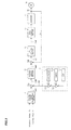
- FIG. 4 is a block diagram showing a configuration example of the present invention.
- FIG. 5 is an image diagram showing a state of a torque occurring between a road surface and a steering
- FIG. 6 is a block diagram showing a configuration in the case of simplifying a vehicle characteristic to a primary delay characteristic by feedback of a yaw rate
- FIG. 7 is a block diagram showing a configuration in the case of performing the same control as performed by the configuration shown in FIG. 6 by feedback of an actual steering angle;
- FIG. 8 is a block diagram in the case of configuring a SAT transfer characteristic control section as a disturbance observer
- FIG. 9 is a block diagram showing a configuration in the case that an actual disturbance is equal to an estimation value of the disturbance observer in the configuration shown in FIG. 8 ;
- FIG. 10 is a block diagram in the case of achieving a small-amplitude disturbance controller by using a structural damping model
- FIG. 11 is a block diagram showing a configuration in the case that a resonance point disturbance controller is a disturbance observer
- FIG. 12 is a block diagram showing a configuration in the case that an actual disturbance is equal to an estimation value of the disturbance observer in the configuration shown in FIG. 11 ;
- FIG. 13 is a block diagram showing a configuration comprising a cant disturbance controller
- FIG. 14 is a block diagram showing a detailed configuration example of the present invention.
- FIG. 15 is a flowchart showing an operating example of the present invention.
- the present invention adapts information of a steering torque to a driver's characteristic on the basis of conditions for enhancing predictability of a vehicle track (hereinafter referred to “prediction enhancement conditions”). Since it is supposed to use the information of the steering torque in addition to conventional visual information in the prediction of the vehicle track, the present invention targets the information of the steering torque.
- the following are enumerated as the prediction enhancement conditions: “to be capable of simplifying a vehicle characteristic observed by the driver to a primary delay characteristic” (hereinafter referred to a “first condition”), “that a time constant of a transfer characteristic of a steering torque to a yaw rate is within an appropriate range” (hereinafter referred to a “second condition”), and “to be capable of controlling sensitivity of a prediction error of the vehicle track to a disturbance so as to be within an acceptable range of the driver” (hereinafter referred to a “third condition”).
- a week understeer characteristic is desirable as the vehicle characteristic with respect to steering operation.
- a damping factor of the week understeer characteristic is about 0.8.
- the characteristic whose damping factor is 0.8 is a good characteristic in both the steering time when the driver steers a vehicle intentionally and the steered time when a vehicle is steered by a disturbance because lateral displacement for a disturbance such as a side wind is modified by the characteristic a little overshooting.
- the first condition is derived from this.
- the vehicle characteristic is defined as a transfer characteristic from an actual steering angle to a yaw rate.
- a transfer characteristic D(s) of that characteristic is the following expression 1.
- FIG. 3 shows a result obtained by measuring a yaw rate characteristic to a steering torque of a vehicle that is evaluated to have a weak understeer characteristic and a good steering feeling.
- the vertical axis shows the steering torque
- the horizontal axis shows the yaw rate
- the results are shown in the cases that a steering input frequency is 0.3 Hz corresponding to a normal operation, 0.5 Hz corresponding to a little rapid lane change, and 1.5 Hz more than them.
- an assist torque occurs from the steering torque of about 2 Nm (newton meter). From FIG. 3 , it is found out that the yaw rate is almost proportional to the steering torque and there is no change by the frequency at 0.3 Hz and 0.5 Hz where the steering input frequency is less than or equal to a yaw rate natural frequency.
- the yaw rate natural frequency of the vehicle is a vibration frequency of free vibration of a steering wheel occurring without a motor of an electric power steering apparatus.
- the transfer characteristic of the steering torque to the yaw rate can be derived by performing a frequency sweep (a change of a frequency at a constant rate) and measuring the steering torque corresponding to the yaw rate at that time.
- the disturbance includes information of a driving environment that is necessary for safety in steering operation. Therefore, the driver needs to recognize the disturbance as the information and control it so that the followability to the target track is not inhibited. Further, since information transfer relating to vehicle behavior and reduction of sensitivity to the disturbance are in the relation of trade-off, the third condition is derived based on these.
- the present invention comprises sections having functions performed to satisfy each condition. Specifically, a vehicle characteristic compensation control section for the first condition, a SAT transfer characteristic control section for the second condition, and a disturbance sensitivity control section for the third condition perform processings respectively to satisfy the conditions. Each section performs the processing to adapt the information of the steering torque to a driver's characteristic. The processings are performed to the detected steering torque in the order of the SAT transfer characteristic control section, the disturbance sensitivity control section, and the vehicle characteristic compensation control section.
- FIG. 4 shows a configuration example of the embodiment of the present invention. Since a configuration of a current command value calculating section 31 is the same as a current command value calculating section 31 shown in FIG. 2 , the explanation is omitted. Further, a configuration after the current command value calculating section 31 are the same as the configuration shown in FIG. 2 , and operations after that are the same as the above operations.
- a SAT estimating section 70 estimates a self-aligning torque (SAT) T SAT by a steering torque Ts, an assist torque Tm, a motor angular velocity ⁇ m, and a motor angular acceleration am.
- a SAT transfer characteristic control section 40 compensates the steering torque Ts on the basis of the estimated SAT T SAT so as to satisfy the second condition, and outputs a compensated steering torque Ts 1 .
- a disturbance sensitivity control section 50 compensates the compensated steering torque Ts 1 on the basis of the estimated SAT T SAT , a steering angle ⁇ g, and a vehicle speed V so as to satisfy the third condition, and outputs a compensated steering torque Ts 2 .
- a vehicle characteristic compensation control section 60 compensates the compensated steering torque Ts 2 on the basis of an actual steering angle ⁇ t so as to satisfy the first condition, and outputs a compensated steering torque Ts 3 to the current command value calculating section 31 .
- a state of a torque occurring between a road surface and a steering is as shown in FIG. 5 .
- the steering torque Ts occurs by a driver steering a steering wheel, and a motor generates the assist torque Tm according to the steering torque Ts.
- wheels are turned, and a SAT occurs as a reaction force.
- a torque which becomes resistance to steering of the steering wheel occurs by an inertia J and a friction (a static friction) Fr of the motor.
- T SAT ( s ) T m ( s )+ T s ( s ) ⁇ J ⁇ m ( s )+ Fr sign( ⁇ m ( s )) [Expression 3]
- the estimated SAT when the estimated SAT is fed back as it is, the steering becomes too heavy, and there are cases where a steering feeling cannot be improved, so that it is possible to perform signal processing with respect to the SAT T SAT by using a filter having a frequency characteristic and output only necessary and sufficient information for improving the steering feeling. Further, it is possible to estimate the SAT by means of a method other than the present method.
- the first condition targeted by the vehicle characteristic compensation control section 60 is a condition relating to the vehicle characteristic.
- the vehicle characteristic is defined as a transfer characteristic from an actual steering torque to a yaw rate.
- the transfer characteristic from the actual steering torque et to the yaw rate r in a two-wheel model is expressed as the following expression 4.
- T STG is a steering torque
- g tot is a total gear ratio
- K STG is a constant
- Vr(s) is a vehicle characteristic
- Cr(s) is a feedback characteristic.
- the configuration comprises a gain section 610 where g tot /K STG is a gain, a characteristic section 620 having the Vr(s), a characteristic section 630 having the Cr(s), and an adding section 640 .
- an electric power steering apparatus cannot directly detect the yaw rate, what the electric power steering apparatus can detect is an actual steering angle, and what it outputs is an assist torque. Therefore, in order to perform control equivalent to performed by the configuration shown in FIG. 6 using an electric power steering mechanism, it is necessary in the configuration shown in FIG. 7 to design a characteristic section 650 having a characteristic Cf(s) that makes the configuration equivalent to shown in FIG. 6 .
- a transfer characteristic of the configuration shown in FIG. 6 and a transfer characteristic of the configuration shown in FIG. 7 are the following expression 8 and expression 9 respectively, and the characteristic Cf(s) that makes the expression 9 equivalent to the expression 8 is given by the following expression 10.
- the damping factor of the yaw rate changes depending on a natural frequency of the electric power steering mechanism forming the steering characteristic, so that it is necessary to adjust the characteristic Cf(s) considering this change.
- the characteristic Cf(s) is adjusted so that a natural frequency ⁇ STG of the electric power steering mechanism approaches to a value of the following expression 14 that makes the damping factor of the yaw rate highest.
- ⁇ STG ⁇ 1 ⁇ SAT ⁇ 1 ⁇ r
- ⁇ STG is a vibration frequency measured in the case of performing impulse steering (an operation of rapidly turning a steering wheel for a moment) and free vibration.
- an appropriate value of the damping factor of the yaw rate is about 0.8.
- an upper limit of a frequency (change rate) of the yaw rate that a driver can control is about 2 Hz, and the yaw rate natural frequency is desirable to be from about 2 Hz to about 4 Hz considering responsiveness of the vehicle that supposes emergency steering.
- the yaw rate natural frequency is from about 0.4 Hz to about 2 Hz, the driver can control it.
- the characteristic Cf (s) is adjusted on the basis of these. Specifically, it is adjusted, for example, so that a pole of the steering characteristic is stable and less than or equal to about 2 Hz.
- control of the yaw rate is possible in the case that the yaw rate natural frequency is less than or equal to about 0.4 Hz, and the yaw rate is made proportional to the steering torque so as to control the yaw rate by the steering torque. Since this is observed in the characteristic shown in FIG. 3 as described above, it can be achieved by satisfying the second condition.
- the vehicle characteristic compensation control section 60 comprises the characteristic section 650 and an adding section 660 that are enclosed with a broken line in FIG. 7 .
- the characteristic section 650 has the characteristic Cf(s) expressed by the expression 13, and transforms the actual steering angle ⁇ t by using the characteristic Cf(s). Further, parameters of the characteristic Cf(s) are adjusted so as to satisfy the expression 14.
- a content of the second condition that the SAT transfer characteristic control section 40 targets is that the time constant of the transfer characteristic of the steering torque to the yaw rate is within an appropriate range as described above.
- the relation between the two changes in accordance with the steering input frequency since the vehicle that is evaluated to have the weak understeer characteristic and a good steering feeling has almost the same characteristic at the steering input frequencies of 0.3 Hz and 0.5 Hz as shown in FIG. 3 , the vehicle track is considered to be easy to predict for the driver. Therefore, such a characteristic can be achieved by a vehicle having an understeer characteristic.
- the SAT transfer characteristic control section 40 deals with this.
- the present embodiment configures the SAT transfer characteristic control section 40 as a disturbance observer. It is because the electric power steering mechanism having a feedback control system can easily obtain a disturbance torque by means of the disturbance observer being an input error model by regarding the SAT as a disturbance.
- FIG. 8 is a block diagram in the case of configuring the SAT transfer characteristic control section 40 as the disturbance observer.
- ⁇ d is a steering angle
- Tr SAT is an actual SAT
- K tor is a torsion bar rigidity
- C(s) is a characteristic of a control system including a torsion bar
- STG(s) is a steering characteristic
- F 1 (s) is a filter characteristic.
- the configuration comprises a gain section 410 where the K tor is a gain, a characteristic section 420 having the C(s), a characteristic section 430 having the STG(s), a characteristic section 440 having a STG ⁇ 1 (s), a filter 450 having the F 1 (s), adding sections 460 and 461 , and subtracting sections 462 and 463 .
- the estimated SAT T SAT is inputted into the filter 450 , and the influence of the ⁇ SAT is compensated by correcting the SAT T SAT in the filter 450 . Therefore, it is necessary to set the F 1 (s) that achieves such a function.
- the T SAT works in such a manner as to pass the T SAT through a characteristic expressed by 1+F 1 (s), as shown in FIG. 9 .
- the T SAT passed through the characteristic expressed by 1+F 1 (s) becomes a characteristic having a desired time constant, it is possible to compensate the influence of the ⁇ SAT .
- a transfer characteristic of the SAT T SAT to the steering angle ⁇ g is expressed by the following expression 15 when the damping factor of the yaw rate approximates 1.
- T SAT G SAT ⁇ ⁇ SAT ⁇ s + 1 ⁇ r ⁇ s + 1 ⁇ ⁇ g [ Expression ⁇ ⁇ 15 ]
- G SAT is a SAT gain.
- the transfer characteristic of the SAT T SAT to the steering angle ⁇ g is expressed by the following expression 16.
- T SATR G SAT ⁇ ⁇ SATR ⁇ s + 1 ⁇ r ⁇ s + 1 ⁇ ⁇ g [ Expression ⁇ ⁇ 16 ]
- T SAT T SATR [Equation 7]
- the F 1 (s) is expressed by the following expression 18.
- the SAT transfer characteristic control section 40 comprises the filter 450 and the adding section 460 that are enclosed with a broken line in FIG. 8 .
- the filter 450 has the characteristic F 1 (s) expressed by the expression 18, and transforms the SAT T SAT by using the characteristic F 1 (s).
- a purpose of the disturbance sensitivity control section 50 is to be capable of controlling the sensitivity of the prediction error of the vehicle track to the disturbance so as to be within an acceptable range of the driver.
- the necessary information of the driving environment is included by the disturbance as described above, all cannot be suppressed.
- the information transfer relating to the vehicle behavior and the reduction of the sensitivity to the disturbance are in the relation of trade-off, it is necessary to keep balance between them. That leads to specifying the disturbance that should be suppressed and suppressing the disturbance individually depending on its characteristic.
- the disturbances that the disturbance sensitivity control section 50 mainly suppresses are a disturbance by small-amplitude torque vibration (a small-amplitude disturbance), a disturbance excited at a resonance point in a longitudinal direction of a suspension (a resonance point disturbance), and a disturbance by a road cant (a cant disturbance).
- the small-amplitude disturbance does not influence the followability to the target track and is not crucially important as the information of the driving environment, suppressing it enables reduction of a driver's load.
- Suppression by structural damping is effective in such a disturbance depending on an amplitude (an amplitude of the steering torque in the present embodiment).
- the structural damping is friction depending on an amplitude of force or a size of displacement, is sometimes called internal damping or hysteresis damping, and is observed on a Lissajous waveform as a hysteresis depending on the amplitude.
- the friction characteristic is given as a function of the SAT. To do so, at first, a structural damping model that should be applied will be described.
- the structural damping is a damping that occurs by an energy loss occurring in a function of displacement that such a viscoelastic body as a rubber has, an imaginary number j is included to express a phase deviation between displacement and speed in the case of integrating a damping term (a damping factor) into a displacement term.
- a damping term a damping factor
- J h is a vibration parameter of steering wheel inertia
- J STG is a vibration parameter of motor inertia
- K SAT is a constant
- ⁇ is a structural damping coefficient.
- a structural damping term is expressed so as to be included by the displacement term.
- j ⁇ K SAT has magnitude proportional to the steering angle ⁇ g, it means that a load works at timing when a phase is shifted by 90 degrees. Therefore, in order to implement the effect of the structural damping, a load whose amplitude is proportional to the ⁇ g can be provided for the damping being a function of a steering angular velocity (a differential value of the ⁇ g).
- F 2 (s) is a filter characteristic.
- the configuration comprises the gain section 410 where the K tor is a gain, the characteristic section 420 having the C(s), the characteristic section 430 having the STG(s), the characteristic section 440 having the STG ⁇ 1 (s), a structural damping model 510 , a filter 511 having the F 2 (s), a differentiating section 512 , the adding section 461 , and subtracting sections 462 , 463 and 513 .
- a controller for the small-amplitude disturbance (hereinafter referred to a “small-amplitude disturbance controller”) in the disturbance sensitivity control section 50 comprises the structural damping model 510 , the filter 511 , the differentiating section 512 , and the subtracting section 513 that are enclosed with a broken line in FIG. 10 .
- An electric power steering apparatus described in this publication brakes a steering wheel returning that occurs by a road surface reaction force by multiplying the SAT by a positive or negative gain according to a judgment result of turning or returning a steering wheel and subtracting its signal from a current command value so that the steering wheel does not return excessively.
- the judgment of turning or returning the steering wheel is performed in a turning returning judging section by using a steering torque and an angular velocity, and the multiplication of the gain is performed in a gain section by inputting the SAT.
- the resonance point in the longitudinal direction of the suspension where the resonance point disturbance is excited is a resonance point that appears by coupling tire rigidity and/or bush rigidity of the suspension to a dynamic characteristic of a steering system.
- a tire shimmy and a brake judder that increase at resonance point in the longitudinal direction of the suspension like this have been dealt with by adopting a bush having a damping characteristic as the bush of the suspension, or mounting a rubber on a sub-frame supporting the suspension.
- these methods provides the steering system with extra compliance, a trade-off problem that the first condition and the second condition among the prediction enhancement conditions become worse arises. Therefore, the present embodiment suppresses the resonance point disturbance by using a disturbance observer. Since the tire shimmy and the brake judder are transmitted to the steering wheel through a steering mechanism, the present embodiment uses a disturbance observer that generates a vibration of opposite phase in a motor and offsets them.
- FIG. 11 is a block diagram in the case of configuring a controller for the resonance point disturbance (hereinafter referred to a “resonance point disturbance controller”) as the disturbance observer.
- F 3 (s) is a filter characteristic.
- the configuration comprises the gain section 410 where the K tor is a gain, the characteristic section 420 having the C(s), the characteristic section 430 having the STG(s), the characteristic section 440 having the STG ⁇ 1 (s), a filter 520 having the F 3 (s), the adding section 461 , and subtracting sections 462 , 463 and 521 .
- the characteristic of the filter 522 is expressed by the following expression 20 where a model that offsets the resonance in the longitudinal direction of the suspension is a numerator and a characteristic after the offset is a denominator.
- the characteristic F 3 (s) of the filter 520 is expressed by the following expression 22.
- F 3 ( s ) 1 - s 2 + 2 ⁇ ⁇ 2 ⁇ ⁇ SUS ⁇ s + ⁇ SUS 2 s 2 + 2 ⁇ ⁇ 1 ⁇ ⁇ SUS ⁇ s + ⁇ SUS 2 [ Expression ⁇ ⁇ 22 ]
- the characteristic F 3 (s) expressed by the expression 22 is a band pass filter characteristic, and is understood to act so as to cancel a resonance peak.
- the resonance point disturbance controller in the disturbance sensitivity control section 50 comprises the filter 520 and the subtracting section 521 that are enclosed with a broken line in FIG. 11 .
- the filter 520 transforms the SAT T SAT by using the characteristic F 3 (s).
- the cant disturbance is a stationary disturbance.
- the stationary disturbance means that the SAT occurring when a vehicle is in a straight running state is offset. Therefore, a controller for the cant disturbance (hereinafter referred to a “cant disturbance controller”) is based on a configuration for detection of the straight running state of the vehicle and an offset correction of the SAT.
- FIG. 13 is a block diagram showing a configuration comprising the cant disturbance controller.
- the configuration comprises the gain section 410 where the K tor is a gain, the characteristic section 420 having the C(s), the characteristic section 430 having the STG(s), the characteristic section 440 having the STG ⁇ 1 (s), a neutral position learning section 530 for neutral position learning, a variable gain section 531 that corrects an offset correction value depending on a vehicle speed, a gradual change section 532 that adjusts the correction so as to gradually perform it, a filter section 533 that transforms the SAT, a switch 534 , the adding section 461 , and subtracting sections 462 , 463 and 535 .
- the cant disturbance controller compensates an influence of a lateral flow by a road cant, it calculates the offset correction value on the basis of the SAT occurring in the straight running state.
- an offset correction value being a base (hereinafter referred to a “basic offset correction value”) is calculated.
- an offset correction value that is ultimately used (hereinafter referred to an “ultimate offset correction value”) is calculated by using the basic offset correction value.
- the basic offset correction value is calculated by using the SAT occurring in the straight running state during an arbitrarily set period (hereinafter referred to a “neutral position learning period”), for example, a predetermined period from a time point when the straight running state is detected.
- the SAT used for the calculation of the basic offset correction value is a SAT transformed in the filter section 533 (hereinafter referred to a “transformed SAT”).
- the filter section 533 suppresses disturbances superimposed on the SAT T SAT except the cant disturbance, for example, the small-amplitude disturbance, and the resonance point disturbance. Therefore, it is possible to use functions of the small-amplitude disturbance controller and the resonance point disturbance controller.
- the calculation of the basic offset correction value (the neutral position learning) is performed in the neutral position learning section 530 .
- the neutral position learning section 530 makes the switch 534 connect with a contact 534 a by sending a command or the like when entering the neutral position learning period, detects the straight running state by judging whether the steering wheel is located near the neutral position, and calculates the basic offset correction value by using the transformed SAT outputted from the filter section 533 when judging the straight running state.
- the neutral position learning section 530 uses known technology for detecting the straight running state, and uses, for example, a mean value of the transformed SAT as the basic offset correction value.
- the neutral position learning section 530 makes the switch 534 connect with a contact 534 b by sending a command or the like when the neutral position learning period terminates.
- the calculated basic offset correction value is stored in the neutral position learning section 530 . With respect to the basic offset correction value, it is possible to use a value other than the mean value such as a mode, or to use other statistical methods.
- the basic offset correction value is transformed by using a vehicle speed correction function so as to be utilized even if the vehicle speed changes, and the correction is gradually performed in order to prevent uncomfortable feeling in the correction process. Since an offset amount of the SAT becomes a function of the vehicle speed in a vehicle having the understeer characteristic, it is expressed as a stationary gain G SAT , which is expressed by using the two-wheel model, and is expressed by the following expression 23.
- G SAT m ⁇ ⁇ L f ⁇ G ⁇ L [ Expression ⁇ ⁇ 23 ]
- G ⁇ 1 1 + KV 2 ⁇ V 2 L [ Expression ⁇ ⁇ 24 ]
- K m 2 ⁇ L 2 ⁇ L f ⁇ K f - L r ⁇ K r K f ⁇ K r [ Expression ⁇ ⁇ 25 ]
- This stationary gain G SAT is used to the vehicle speed correction function.
- the switch 534 connects with the contact 534 b , and the gradual change section 532 inputs the basic offset correction value that has been stored in the neutral position learning section 530 .
- the gradual change section 532 outputs 1/N-fold (N is an arbitrary natural number) data of the basic offset correction value, and then outputs data that increase at such a constant rate as 2/N times and 3/N times (hereinafter processing in the gradual change section 532 is referred to “gradual change processing”).
- gradient change processing processing in the gradual change section 532 is referred to “gradual change processing”.
- variable gain section 531 inputs the data outputted from the gradual change section 532 , multiplies it by the stationary gain G SAT calculated by using the inputted vehicle speed V, and outputs the multiplication result as the ultimate offset correction value.
- a predetermined maximum value for example, 3 Nm
- the cant disturbance controller in the disturbance sensitivity control section 50 comprises the neutral position learning section 530 , the variable gain section 531 , the gradual change section 532 , the filter section 533 , the switch 534 and the subtracting section 535 that are enclosed with a broken line in FIG. 13 .
- the disturbance sensitivity control section 50 may suppress disturbances other than the small-amplitude disturbance, the resonance point disturbance and the cant disturbance.
- the disturbance sensitivity control section 50 may suppress an influence of a side wind as the disturbance.
- the disturbance sensitivity control section 50 suppresses track change of a vehicle corresponding to force provided for a vehicle body by the side wind, especially lateral displacement.
- the weak understeer characteristic is desirable. It is because the lateral displacement occurring once is returned by the phenomenon that the yaw rate slightly vibrates in the weak understeer characteristic.
- the damping factor of the yaw rate is preferably about 0.8. The influence of the side wind is suppressed by using such a controller as achieves this damping factor.
- the neutral position learning period set to the cant disturbance controller of the disturbance sensitivity control section 50 is the predetermined period (for example, 5 minutes) from the time point when the straight running state is detected, and in the following explanation of the operation, it is supposed that the neutral position learning section 530 has stored the mean value calculated by using the transformed SAT at a time point when the straight running state is judged among the transformed SATs inputted from the filter section 533 during the neutral position learning period as the basic offset correction value, and that the switch 534 has connected with the contact 534 b.
- Step S 1 When the operation is started, the steering torque Ts, the motor angular velocity ⁇ m, the motor angular acceleration am, the assist torque Tm, the steering angle ⁇ g, the actual steering angle ⁇ t, and the vehicle speed V are inputted (Step S 1 ).
- the steering torque Ts is inputted into the adding section 460 and the SAT estimating section 70
- the motor angular velocity ⁇ m, the motor angular acceleration am and the assist torque Tm are inputted into the SAT estimating section 70
- the steering angle ⁇ g is inputted into the differentiating section 512 of the disturbance sensitivity control section 50
- the actual steering angle ⁇ t is inputted into the characteristic section 650 of the vehicle characteristic compensation control section 60
- the vehicle speed V is inputted into the variable gain section 531 of the disturbance sensitivity control section 50 and the current command value calculating section 31 .
- the SAT estimating section 70 calculates the SAT T SAT on the basis of the expression 3 by using the steering torque Ts, the motor angular velocity ⁇ m, the motor angular acceleration ⁇ m and the assist torque Tm (Step S 2 ).
- the calculated SAT T SAT is inputted into the filter 450 of the SAT transfer characteristic control section 40 , and the filter 511 , the filter 520 and the filter section 533 of the disturbance sensitivity control section 50 .
- the filter 450 corrects the SAT T SAT in accordance with the characteristic F 1 (s) expressed by the expression 18 (Step S 3 ), and outputs a compensation signal Cs 1 to the adding section 460 .
- the adding section 460 adds the compensation signal Cs 1 to the steering torque Ts, and outputs the compensated steering torque Ts 1 (Step S 4 ).
- a compensation signal Cs 2 for suppressing the small-amplitude disturbance is obtained by the structural damping model 510 , the filter 511 and the differentiating section 512 of the small-amplitude disturbance controller using the SAT T SAT and the steering angle ⁇ g (moreover, the steering torque Ts in some cases) (Step S 5 ).
- the compensation signal Cs 2 is inputted into the subtracting section 513 , the compensation signal Cs 2 is subtracted from the compensated steering torque Ts 1 , and a compensated steering torque Ts 2 a is outputted (Step S 6 ).
- the filter 520 of the disturbance sensitivity control section 50 inputting the SAT T SAT corrects the SAT T SAT so as to suppress the resonance point disturbance in accordance with the characteristic F 3 (s) expressed by the expression 22 (Step S 7 ), and outputs a compensation signal Cs 3 to the subtracting section 521 .
- the subtracting section 521 subtracts the compensation signal Cs 3 from the compensated steering torque Ts 2 a , and outputs a compensated steering torque Ts 2 b (Step S 8 ).
- the gradual change section 532 and the variable gain section 531 of the disturbance sensitivity control section 50 calculate an ultimate offset correction value Oc for suppressing the cant disturbance by the gradual change processing, multiplication of the stationary gain G SAT and maximum value limitation using the basic offset correction value stored in the neutral position learning section 530 (Step S 9 ).
- the ultimate offset correction value Oc is inputted into the subtracting section 535 , the ultimate offset correction value Oc is subtracted from the compensated steering torque Ts 2 b , and the compensated steering torque Ts 2 is outputted (Step S 10 ).
- the characteristic section 650 of the vehicle characteristic compensation control section 60 inputting the actual steering angle ⁇ t obtains a compensation signal Cs 4 in accordance with the characteristic Cf(s) expressed by the expression 13 using the actual steering angle ⁇ t (Step S 11 ).
- the compensation signal Cs 4 is inputted into the adding section 660 , the compensation signal Cs 4 is added to the compensated steering torque Ts 2 , and the compensated steering torque Ts 3 is outputted (Step S 12 ).
- the compensated steering torque Ts 3 is inputted into the current command value calculating section 31 .
- the vehicle characteristic compensation control section may approximates it to the primary delay characteristic by other methods.
- the SAT transfer characteristic control section is configured as the disturbance observer, the SAT transfer characteristic control section may be configured as two-degree configurations other than it.
Landscapes
- Engineering & Computer Science (AREA)
- Chemical & Material Sciences (AREA)
- Combustion & Propulsion (AREA)
- Transportation (AREA)
- Mechanical Engineering (AREA)
- Steering Control In Accordance With Driving Conditions (AREA)
- Power Steering Mechanism (AREA)
Applications Claiming Priority (3)
| Application Number | Priority Date | Filing Date | Title |
|---|---|---|---|
| JP2015128761 | 2015-06-26 | ||
| JP2015-128761 | 2015-06-26 | ||
| PCT/JP2016/068637 WO2016208665A1 (ja) | 2015-06-26 | 2016-06-23 | 電動パワーステアリング機構を用いた運転支援制御装置 |
Publications (2)
| Publication Number | Publication Date |
|---|---|
| US20180111642A1 US20180111642A1 (en) | 2018-04-26 |
| US10160482B2 true US10160482B2 (en) | 2018-12-25 |
Family
ID=57584998
Family Applications (1)
| Application Number | Title | Priority Date | Filing Date |
|---|---|---|---|
| US15/544,978 Expired - Fee Related US10160482B2 (en) | 2015-06-26 | 2016-06-23 | Driving support control apparatus using electric power steering mechanism |
Country Status (5)
| Country | Link |
|---|---|
| US (1) | US10160482B2 (ja) |
| EP (1) | EP3246227B1 (ja) |
| JP (1) | JP6112275B1 (ja) |
| CN (1) | CN107848571B (ja) |
| WO (1) | WO2016208665A1 (ja) |
Families Citing this family (28)
| Publication number | Priority date | Publication date | Assignee | Title |
|---|---|---|---|---|
| KR102350043B1 (ko) * | 2015-11-20 | 2022-01-12 | 주식회사 만도 | 자동 조향 제어 시스템 및 방법 |
| JP6760799B2 (ja) * | 2016-08-26 | 2020-09-23 | 株式会社ジェイテクト | 操舵制御装置 |
| JP6787174B2 (ja) * | 2017-02-22 | 2020-11-18 | トヨタ自動車株式会社 | 駆動力制御装置 |
| EP3604083B1 (en) * | 2017-03-27 | 2021-06-30 | Mitsubishi Electric Corporation | Electric power steering device |
| JP2019023038A (ja) * | 2017-07-24 | 2019-02-14 | 株式会社ジェイテクト | 操舵制御装置 |
| JP7264058B2 (ja) | 2017-11-02 | 2023-04-25 | 株式会社ジェイテクト | 操舵制御装置 |
| FR3077263B1 (fr) * | 2018-01-31 | 2021-01-08 | Jtekt Europe Sas | Amelioration de l’evaluation de la position angulaire absolue d’un volant de conduite par prise en consideration de la situation lors de la coupure de contact du vehicule |
| US10940884B2 (en) * | 2018-06-08 | 2021-03-09 | GM Global Technology Operations LLC | Systems and methods for brake pull mitigation |
| JP6543393B1 (ja) * | 2018-06-29 | 2019-07-10 | 株式会社ショーワ | ステアリング制御装置及びステアリング装置 |
| JP7087854B2 (ja) * | 2018-09-07 | 2022-06-21 | 株式会社デンソー | ステアリング制御装置 |
| CN112770960B (zh) * | 2018-09-26 | 2023-10-10 | 日本电产株式会社 | 转向控制装置和助力转向装置 |
| WO2020157683A1 (en) * | 2019-01-29 | 2020-08-06 | Aptiv Technologies Limited | Electric power steering torque compensation |
| JP7256958B2 (ja) * | 2019-05-27 | 2023-04-13 | 株式会社ジェイテクト | 電動パワーステアリング装置 |
| JPWO2021029331A1 (ja) * | 2019-08-09 | 2021-02-18 | ||
| WO2021029329A1 (ja) * | 2019-08-09 | 2021-02-18 | 日本電産株式会社 | 制御装置、駆動装置、電動パワーステアリング装置及び制御方法 |
| KR102703073B1 (ko) | 2019-11-19 | 2024-09-05 | 현대자동차주식회사 | 외란 보상 조향제어 방법 및 전동조향장치 |
| KR102445203B1 (ko) * | 2020-12-10 | 2022-09-20 | 현대모비스 주식회사 | 조향 휠의 진동 저감 장치 및 방법 |
| US12077231B2 (en) * | 2021-02-19 | 2024-09-03 | Hl Mando Corporation | Apparatus and method for controlling steer-by-wire system to provide improved feedback to steering wheel |
| DE102021202482B4 (de) * | 2021-03-15 | 2023-06-29 | Continental Automotive Technologies GmbH | Regelungseinrichtung und Verfahren zur Lenkwinkelregelung eines Fahrzeugs |
| US12172706B2 (en) | 2021-09-29 | 2024-12-24 | Nidec Corporation | Motor control device, motor control method, motor module, and electric power steering device |
| US20230103267A1 (en) | 2021-09-29 | 2023-03-30 | Nidec Corporation | Motor control device, motor control method, motor module, and electric power steering device |
| US12202554B2 (en) | 2021-09-29 | 2025-01-21 | Nidec Corporation | Motor control device, motor control method, motor module, and electric power steering device |
| JP7736561B2 (ja) * | 2021-12-28 | 2025-09-09 | ニデック株式会社 | 制御装置、電動パワーステアリング装置、および制御方法 |
| CN116923528B (zh) * | 2022-03-30 | 2026-04-10 | 本田技研工业株式会社 | 转矩传感器故障检测方法 |
| CN117207952A (zh) * | 2022-06-02 | 2023-12-12 | 本田技研工业株式会社 | 车辆转向行驶控制装置 |
| CN119218294A (zh) * | 2023-06-29 | 2024-12-31 | 尼得科株式会社 | 控制装置和转向装置 |
| CN119218292A (zh) * | 2023-06-29 | 2024-12-31 | 尼得科株式会社 | 控制装置、电动助力转向装置以及控制方法 |
| CN117666358B (zh) * | 2023-12-13 | 2025-03-25 | 哈尔滨工业大学 | 一种自适应扰动观测补偿的飞行器姿态预测控制方法 |
Citations (7)
| Publication number | Priority date | Publication date | Assignee | Title |
|---|---|---|---|---|
| JPH0867267A (ja) | 1994-06-24 | 1996-03-12 | Toyota Motor Corp | 操舵反力制御装置 |
| JP2007302017A (ja) | 2006-05-08 | 2007-11-22 | Nsk Ltd | 電動パワーステアリング装置の制御装置 |
| JP2008018825A (ja) | 2006-07-12 | 2008-01-31 | Nsk Ltd | 電動パワーステアリング装置の制御装置 |
| US20100280715A1 (en) * | 2005-01-14 | 2010-11-04 | Nsk Ltd. | Control apparatus for electric power steering apparatus |
| JP5291640B2 (ja) | 2010-01-14 | 2013-09-18 | 株式会社豊田中央研究所 | 操舵装置 |
| US20130245890A1 (en) * | 2010-11-29 | 2013-09-19 | Nissan Motor Co., Ltd. | Vehicle, and method for steering control of same |
| US20150291210A1 (en) * | 2012-11-07 | 2015-10-15 | Nissan Motor Co., Ltd. | Steering control device |
Family Cites Families (3)
| Publication number | Priority date | Publication date | Assignee | Title |
|---|---|---|---|---|
| JP4128719B2 (ja) * | 2000-02-25 | 2008-07-30 | 三菱電機株式会社 | 電動式パワーステアリング制御装置及びその制御方法 |
| JP4192442B2 (ja) * | 2001-06-07 | 2008-12-10 | 日本精工株式会社 | 電動パワーステアリング装置の制御装置 |
| JP4362137B2 (ja) * | 2007-02-28 | 2009-11-11 | 三菱電機株式会社 | 車両用操舵装置 |
-
2016
- 2016-06-23 WO PCT/JP2016/068637 patent/WO2016208665A1/ja not_active Ceased
- 2016-06-23 US US15/544,978 patent/US10160482B2/en not_active Expired - Fee Related
- 2016-06-23 EP EP16814434.3A patent/EP3246227B1/en not_active Not-in-force
- 2016-06-23 CN CN201680037237.4A patent/CN107848571B/zh not_active Expired - Fee Related
- 2016-06-23 JP JP2016568714A patent/JP6112275B1/ja active Active
Patent Citations (8)
| Publication number | Priority date | Publication date | Assignee | Title |
|---|---|---|---|---|
| JPH0867267A (ja) | 1994-06-24 | 1996-03-12 | Toyota Motor Corp | 操舵反力制御装置 |
| US20100280715A1 (en) * | 2005-01-14 | 2010-11-04 | Nsk Ltd. | Control apparatus for electric power steering apparatus |
| JP2007302017A (ja) | 2006-05-08 | 2007-11-22 | Nsk Ltd | 電動パワーステアリング装置の制御装置 |
| US20100168963A1 (en) | 2006-05-08 | 2010-07-01 | Nsk Ltd. | Control system for electronic power steering |
| JP2008018825A (ja) | 2006-07-12 | 2008-01-31 | Nsk Ltd | 電動パワーステアリング装置の制御装置 |
| JP5291640B2 (ja) | 2010-01-14 | 2013-09-18 | 株式会社豊田中央研究所 | 操舵装置 |
| US20130245890A1 (en) * | 2010-11-29 | 2013-09-19 | Nissan Motor Co., Ltd. | Vehicle, and method for steering control of same |
| US20150291210A1 (en) * | 2012-11-07 | 2015-10-15 | Nissan Motor Co., Ltd. | Steering control device |
Non-Patent Citations (2)
| Title |
|---|
| International Search Report for PCT/JP2016/068637 dated Aug. 23, 2016 [PCT/ISA/210]. |
| Written Opinion for PCT/JP2016/068637 dated Aug. 23, 2016 [PCT/ISA/237]. |
Also Published As
| Publication number | Publication date |
|---|---|
| US20180111642A1 (en) | 2018-04-26 |
| JP6112275B1 (ja) | 2017-04-12 |
| EP3246227A4 (en) | 2018-02-28 |
| JPWO2016208665A1 (ja) | 2017-06-22 |
| CN107848571B (zh) | 2019-02-15 |
| CN107848571A (zh) | 2018-03-27 |
| WO2016208665A1 (ja) | 2016-12-29 |
| EP3246227A1 (en) | 2017-11-22 |
| EP3246227B1 (en) | 2019-05-01 |
Similar Documents
| Publication | Publication Date | Title |
|---|---|---|
| US10160482B2 (en) | Driving support control apparatus using electric power steering mechanism | |
| US10300942B2 (en) | Electric power steering apparatus | |
| US8820469B2 (en) | Electric power steering apparatus | |
| US9327761B2 (en) | Electric power steering apparatus | |
| Zhao et al. | Displacement and force coupling control design for automotive active front steering system | |
| US10526009B2 (en) | Electric power steering apparatus | |
| JP4281828B2 (ja) | 電動パワーステアリング装置 | |
| EP3031701B1 (en) | Electric power steering device | |
| EP2915722B1 (en) | Electric power steering device | |
| US20220315103A1 (en) | Vehicle steering device | |
| US11034382B2 (en) | Steering apparatus for vehicles | |
| US20170137057A1 (en) | Electric power steering apparatus | |
| US12084122B2 (en) | Steering apparatus for vehicles | |
| JP2006151360A (ja) | 車両用操舵装置 | |
| JP7347493B2 (ja) | 車両用操向装置 | |
| JP6701946B2 (ja) | 電動パワーステアリング機構を用いた運転支援制御装置及びそれを搭載した車両 | |
| JP2009143368A (ja) | 電動パワーステアリング装置 |
Legal Events
| Date | Code | Title | Description |
|---|---|---|---|
| STCF | Information on status: patent grant |
Free format text: PATENTED CASE |
|
| FEPP | Fee payment procedure |
Free format text: MAINTENANCE FEE REMINDER MAILED (ORIGINAL EVENT CODE: REM.); ENTITY STATUS OF PATENT OWNER: LARGE ENTITY |
|
| LAPS | Lapse for failure to pay maintenance fees |
Free format text: PATENT EXPIRED FOR FAILURE TO PAY MAINTENANCE FEES (ORIGINAL EVENT CODE: EXP.); ENTITY STATUS OF PATENT OWNER: LARGE ENTITY |
|
| STCH | Information on status: patent discontinuation |
Free format text: PATENT EXPIRED DUE TO NONPAYMENT OF MAINTENANCE FEES UNDER 37 CFR 1.362 |
|
| FP | Lapsed due to failure to pay maintenance fee |
Effective date: 20221225 |