US10162089B2 - Light amount adjustment device and optical device - Google Patents
Light amount adjustment device and optical device Download PDFInfo
- Publication number
- US10162089B2 US10162089B2 US14/808,064 US201514808064A US10162089B2 US 10162089 B2 US10162089 B2 US 10162089B2 US 201514808064 A US201514808064 A US 201514808064A US 10162089 B2 US10162089 B2 US 10162089B2
- Authority
- US
- United States
- Prior art keywords
- light amount
- amount adjustment
- movement
- units
- light
- Prior art date
- Legal status (The legal status is an assumption and is not a legal conclusion. Google has not performed a legal analysis and makes no representation as to the accuracy of the status listed.)
- Active, expires
Links
- 230000003287 optical effect Effects 0.000 title claims description 61
- 230000033001 locomotion Effects 0.000 claims abstract description 92
- 238000002834 transmittance Methods 0.000 claims description 16
- 239000003086 colorant Substances 0.000 claims description 14
- 230000007246 mechanism Effects 0.000 description 48
- 238000003384 imaging method Methods 0.000 description 12
- 230000003247 decreasing effect Effects 0.000 description 4
- 230000009467 reduction Effects 0.000 description 3
- 230000001174 ascending effect Effects 0.000 description 2
- 230000008859 change Effects 0.000 description 2
- 238000000034 method Methods 0.000 description 2
- 230000003252 repetitive effect Effects 0.000 description 2
- 239000000758 substrate Substances 0.000 description 2
- 230000005540 biological transmission Effects 0.000 description 1
- 239000000470 constituent Substances 0.000 description 1
- 230000007423 decrease Effects 0.000 description 1
- 230000007613 environmental effect Effects 0.000 description 1
- 238000004519 manufacturing process Methods 0.000 description 1
- 238000005259 measurement Methods 0.000 description 1
- 238000012986 modification Methods 0.000 description 1
- 230000004048 modification Effects 0.000 description 1
- 230000036544 posture Effects 0.000 description 1
Images




Classifications
-
- G—PHYSICS
- G02—OPTICS
- G02B—OPTICAL ELEMENTS, SYSTEMS OR APPARATUS
- G02B5/00—Optical elements other than lenses
- G02B5/20—Filters
- G02B5/22—Absorbing filters
-
- G—PHYSICS
- G02—OPTICS
- G02B—OPTICAL ELEMENTS, SYSTEMS OR APPARATUS
- G02B5/00—Optical elements other than lenses
- G02B5/20—Filters
- G02B5/208—Filters for use with infrared or ultraviolet radiation, e.g. for separating visible light from infrared and/or ultraviolet radiation
-
- G—PHYSICS
- G03—PHOTOGRAPHY; CINEMATOGRAPHY; ANALOGOUS TECHNIQUES USING WAVES OTHER THAN OPTICAL WAVES; ELECTROGRAPHY; HOLOGRAPHY
- G03B—APPARATUS OR ARRANGEMENTS FOR TAKING PHOTOGRAPHS OR FOR PROJECTING OR VIEWING THEM; APPARATUS OR ARRANGEMENTS EMPLOYING ANALOGOUS TECHNIQUES USING WAVES OTHER THAN OPTICAL WAVES; ACCESSORIES THEREFOR
- G03B11/00—Filters or other obturators specially adapted for photographic purposes
-
- G—PHYSICS
- G03—PHOTOGRAPHY; CINEMATOGRAPHY; ANALOGOUS TECHNIQUES USING WAVES OTHER THAN OPTICAL WAVES; ELECTROGRAPHY; HOLOGRAPHY
- G03B—APPARATUS OR ARRANGEMENTS FOR TAKING PHOTOGRAPHS OR FOR PROJECTING OR VIEWING THEM; APPARATUS OR ARRANGEMENTS EMPLOYING ANALOGOUS TECHNIQUES USING WAVES OTHER THAN OPTICAL WAVES; ACCESSORIES THEREFOR
- G03B9/00—Exposure-making shutters; Diaphragms
- G03B9/02—Diaphragms
Definitions
- the present invention relates to a light amount adjustment technique.
- An optical device such as a camera or interchangeable lens sometimes includes a light amount adjustment member such as an ND filter, IR cut filter, or deflection filter in order to adjust the light amount.
- a light amount adjustment member such as an ND filter, IR cut filter, or deflection filter in order to adjust the light amount.
- Japanese Patent Laid-Open No. 2002-176573 has disclosed a device capable of switching filters to be used to adjust the light amount by linearly moving a filter holder integrally holding a plurality of filters.
- the device disclosed in Japanese Patent Laid-Open No. 2002-176573 has an arrangement in which the plurality of filters are mounted as they are arranged in one direction in the filter holder, and all the filters are moved at once by a single moving mechanism.
- the number of filters is increased, therefore, the length of the filter holder increases in proportional to the number of filters, and this makes miniaturization of the device difficult.
- the present invention provides a technique capable of miniaturizing a light amount adjustment device and optical device.
- a light amount adjustment device comprising a light path forming member including an aperture for forming a light path, a plurality of light amount adjustment members configured to adjust an amount of light passing through the aperture, and a plurality of movement units configured to linearly advance and retract the light amount adjustment members with respect to the aperture.
- an optical device comprising the light amount adjustment device.
- FIG. 1 is an exploded perspective view of a light amount adjustment device according to an embodiment of the present invention
- FIG. 2 is an exploded perspective view in which the light amount adjustment device shown in FIG. 1 is viewed in the opposite direction;
- FIG. 3A is an assembly view of the light amount adjustment device shown in FIG. 1 with some parts being removed;
- FIG. 3B is a sectional view of the light amount adjustment device shown in FIG. 1 ;
- FIG. 4A is a perspective view of some parts of the light amount adjustment device shown in FIG. 1 ;
- FIG. 4B is a perspective view of some parts of the light amount adjustment device shown in FIG. 1 ;
- FIG. 5 is an exploded perspective view of some parts of the light amount adjustment device shown in FIG. 1 ;
- FIG. 6 is an exploded perspective view of some parts of the light amount adjustment device shown in FIG. 1 ;
- FIG. 7 is an exploded perspective view of the light amount adjustment device shown in FIG. 1 ;
- FIG. 8 is a schematic view of an optical device including the light amount adjustment device shown in FIG. 1 ;
- FIG. 9A is a perspective view of a light amount adjustment device according to the third embodiment.
- FIG. 9B is a perspective view of a light amount adjustment device according to the fourth embodiment.
- FIGS. 1 and 2 are exploded perspective views of the light amount adjustment device A when it is viewed in opposite directions.
- the light amount adjustment device A includes a base plate 1 , a cover 2 , a plurality of filter units 3 A to 3 D (to be also referred to as filter units 3 when collectively called), driving units DU 1 and DU 2 , and a guide unit 7 .
- FIG. 3A is an assembly view of the light amount adjustment device A with the cover 2 being removed.
- FIG. 3B is a sectional view of the light amount adjustment device A.
- the base plate 1 is a flat plate, and has an aperture 1 a which forms a light path.
- a retraction space forming portion 1 b for forming a retraction space which allows the filter units 3 A to 3 D to retract outside the aperture 1 a is formed below it.
- the central-line direction (an arrow d 1 in FIG. 3B ) of the aperture 1 a will sometimes be called an optical-axis direction hereinafter.
- the driving units DU 1 and DU 2 and guide unit 7 are fixed to the base plate 1 .
- the cover 2 has a boxy shape having an open rear portion, and has an aperture 2 a for forming a light path in the front surface.
- the aperture 2 a is formed in a position overlapping the aperture 1 a in the optical-axis direction.
- a retraction space forming portion 2 b for forming a retraction space which allows the filter units 3 A to 3 D to retract outside the aperture 2 a is formed below it.
- the base plate 1 is attached to the rear surface of the cover 2 , thereby forming a boxy hollow member as a whole.
- the aperture 2 a is set to be smaller than the aperture 1 a .
- incident light passes in the order of aperture 2 a ⁇ aperture 1 a .
- the base plate 1 and cover 2 form light path forming members.
- the space between the retraction space forming portions 1 b and 2 b functions as the retraction space for the filter units 3 A to 3 D.
- the filter units 3 A to 3 D respectively include plate-like light amount adjustment members 31 A to 31 D (to be also referred to as light amount adjustment members 31 when collectively called).
- Each of the light amount adjustment members 31 A to 31 D is an optical member such as an ND filter, IR cut filter, or deflection filter.
- the light amount adjustment members 31 A to 31 D can be different kinds of optical members or the same kind of optical members. It is also possible to use both the same kind of optical members and different kinds of optical members. When using the same kind of optical members, for example, light reduction filters, the light reduction amount can be changed by the number of filter units 3 to be advanced on the apertures 1 a and 2 a.
- the filter units 3 A to 3 D are arranged in the optical-axis direction. More specifically, the light amount adjustment members 31 A to 31 D are arranged such that the normal direction is parallel to the optical-axis direction, thereby forming a four-layered structure.
- the pair of driving units DU 1 and DU 2 moves the filter units 3 A to 3 D.
- the driving units DU 1 and DU 2 oppose each other with the apertures 1 a and 2 a being sandwiched between them.
- the number of driving units DU is two in this embodiment, it may also be one or three or more and is properly selected in accordance with the number of filter units 3 .
- the driving unit DU linearly moves the filter unit 3 in a direction perpendicular to the optical-axis direction, between a position on the apertures 1 a and 2 a and a position in the retraction space.
- the filter unit 3 is moved to the position on the apertures 1 a and 2 a , incident light passes through the light amount adjustment member 31 of the filter unit 3 , so the light amount can be adjusted.
- the guide unit 7 guides the movement of the filter unit 3 .
- the filter units 3 A to 3 D can individually be moved independently of each other as will be described below. Consequently, it is possible to individually linearly advance and retract the light amount adjustment members 31 A to 31 D with respect to the apertures 1 a and 2 a .
- the driving units DU 1 and DU 2 and guide unit 7 will be explained with reference to FIGS. 4A, 4B, and 5 .
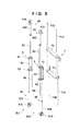
- FIG. 4A is a perspective view of the driving units DU 1 and DU 2 and guide unit 7 .
- FIG. 4B is a perspective view of the driving units DU 1 and DU 2 when they are viewed in a direction different from that of FIG. 4A .
- FIG. 5 is an exploded perspective view of the driving units DU 1 and DU 2 and guide unit 7 .
- the driving unit DU 1 includes movement mechanisms 4 A and 4 C as portions of movement units, a support member 5 , and guide shafts 6 A and 6 C as guide members.
- the driving unit DU 2 includes movement mechanisms 4 B and 4 D, a support member 5 , and guide shafts 6 B and 6 D.
- the movement mechanisms 4 A to 4 D (to be also referred to as movement mechanisms 4 when collectively called) are mechanisms for moving the filter units 3 A to 3 D, respectively.
- the guide shafts 6 A to 6 D (to be also referred to as guide shafts 6 when collectively called) are formed as rotation stoppers for the filter units 3 A to 3 D, and also have a function of guiding the movement of the filter units 3 A to 3 D.
- the movement mechanism 4 A includes a motor 41 A and converter 42 A.
- the motor 41 A is a stepping motor in this embodiment, it may also be another kind of motor.
- the converter 42 A is a mechanism which converts the output from the motor 41 A into a linear motion and linearly moves the filter unit 3 A along a direction in which the driving shaft of the converter 42 A extends, and is a lead screw in this embodiment.
- the driving shaft of the converter 42 A need only have a length covering the range from one end to the other end of the aperture. In this case, the filter unit 3 A can stably be moved even if the driving shaft of the converter 42 A does not extend over the apertures 1 a and 2 a.
- the movement mechanisms 4 B to 4 D have the same arrangement as that of the movement mechanism 4 A. That is, the movement mechanism 4 B includes a motor 41 B and converter 42 B, the movement mechanism 4 C includes a motor 41 C and converter 42 C, and the movement mechanism 4 D includes a motor 41 D and converter 42 D.
- the motors 41 A to 41 D will be referred to as motors 41 when collectively called, and the converters 42 A to 42 D will be referred to as converters 42 when collectively called.
- the movement mechanism 4 includes the motor 41 and converter 42 in this embodiment, but it is, of course, also possible to adopt another arrangement.
- the movement mechanism 4 can also include a piezoelectric element, and a driving rod connected to the piezoelectric element.
- the support member 5 is common to a plurality of movement mechanisms 4 .
- the support member 5 supports two movement mechanisms 4 . It is, of course, also possible to adopt an arrangement in which the support member 5 supports three or more movement mechanisms.
- the support member 5 includes a pair of motor support portions 51 and 52 spaced apart from and opposing each other, and an attaching portion 53 connecting the motor support portions 51 and 52 and fixed to the base plate 1 .
- the support member 5 may also be integrated with the base plate 1 .
- the motor 41 is fixed to the motor support portions 51 and 52 .
- the converter 42 is disposed between the motor support portions 51 and 52 such that one end is connected to the motor 41 , and the other end is rotatably axially supported by the motor support portion 51 or 52 .
- the guide shaft 6 is extended parallel to the converter 42 between the motor support portions 51 and 52 .
- the movement mechanisms 4 A and 4 C are supported by the support member 5 , the motor 41 A is supported by the motor support portion 51 , and the motor 41 C is supported by the motor support portion 52 . That is, the movement mechanisms 4 A and 4 C are attached parallel to each other as they are vertically inverted.
- the movement mechanisms 4 B and 4 D are supported by the support member 5 , the motor 41 B is supported by the motor support portion 52 , and the motor 41 D is supported by the motor support portion 51 . That is, the movement mechanisms 4 B and 4 D are attached parallel to each other as they are vertically inverted.
- the motors 41 are arranged such that they are vertically inverted. When compared to a case in which the motors 41 are juxtaposed adjacent to each other, therefore, the device can be miniaturized by effectively using the dead space. It is also possible to move the filter units 3 in a narrow space in the optical-axis direction without any interference between them.
- portions (the converters 42 ) of the movement mechanisms 4 A and 4 C are so arranged as to overlap each other in the optical-axis direction, so the driving units DU 1 and DU 2 can be miniaturized. Note that this similarly applies to the movement mechanisms 4 B and 4 D.
- the miniaturization of the driving units DU 1 and DU 2 largely contributes to the miniaturization of the light amount adjustment device A.
- this embodiment has exemplified the structure in which the two converters 42 are arranged to overlap each other in the optical-axis direction in the driving units DU 1 and DU 2 , but the two converters 42 may also be arranged so as not to overlap each other in the optical-axis direction. This is so because, as will be described in detail later, it is possible to sufficiently miniaturize the light amount adjustment device A by arranging at least portions of the driving units DU 1 and DU 2 such that these portions overlap each other.
- the guide unit 7 includes a pair of support portions 72 and 73 , and guide members 71 A to 71 D (to be also referred to as guide members 71 when collectively called) extended between them.
- the support portions 72 and 73 are fixed to the base plate 1 .
- the support portions 72 and 73 may also be integrated with the base plate 1 .
- the guide member 71 is a columnar shaft and has a diameter larger than that of the guide shaft 6 .
- the guide member 71 A guides the movement of the filter unit 3 A, that is, the movement of the light amount adjustment member 3 A, and the guide member 71 B guides the movement of the filter unit 3 B. Similarly, the guide member 71 C guides the movement of the filter unit 3 C, and the guide member 71 D guides the movement of the filter unit 3 D.
- the guide shaft 6 B and guide member 71 A are positioned parallel to each other on the same plane perpendicular to the optical-axis direction (d 1 ).
- the converter 42 A is positioned to be slightly shifted from this plane in the optical-axis direction. This applies to the relationships between the movement mechanisms 4 B to 4 D and guide members 71 B to 71 D.
- the guide members 71 are formed in the driving units DU 1 and DU 2 . In this case, the guide member 71 is extended between the motor supports portions 51 and 52 .
- FIG. 6 is an exploded perspective view of the filter units 3 A to 3 D.
- FIG. 7 is an exploded perspective view of the light amount adjustment device A, which shows the way the individual components are screwed.
- the cover 2 , the plurality of filter units 3 A to 3 D, the driving units DU 1 and DU 2 , and the guide unit 7 are screwed to the base plate 1 .
- the filter unit 3 includes the three members, but the number of constituent members is not limited.
- the filter units 3 A to 3 D have arrangements in which the light amount adjustment members 31 A to 31 D as a plurality of optical filter elements having different light transmittances are clamped and held by holding members 32 A to 32 D and press plates 33 A to 33 D.
- the light amount adjustment device A includes the plurality of optical filter elements having different light transmittances.
- the amount of light entering an image sensor can be adjusted by switching the optical filter elements to be inserted into the light path.
- the optical filter element is a member which adjusts the transmission of light.
- the plurality of optical filter elements may also be held on a single substrate, and form regions having different densities as one optical filter.
- the light amount adjustment device A includes a plurality of optical filters.
- the plurality of optical filter elements may also be arranged in different optical filters.
- the light amount adjustment device may also include one optical filter, and a plurality of optical filter elements may also be arranged in the optical filter.
- the light amount adjustment members 31 A to 31 D as a plurality of optical filter elements are held by the different holding members 32 A to 32 D.
- the light amount adjustment device A includes the four light amount adjustment members 31 A to 31 D.
- the number of optical filter elements of the light amount adjustment device A is not limited to this, and the light amount adjustment device A need only include two or more optical filter elements.
- the light amount adjustment members 31 A to 31 D have different optical densities. That is, the light amount adjustment members 31 A to 31 D have different light transmittances.
- This optical filter element can be a light reduction filter such as an ND filter.
- the light amount adjustment device A may include three or more ND filter elements having different light transmittances, and includes three ND filters and one AR filter as a plurality of optical filter elements.
- the light amount adjustment device A includes an AR filter (called ND_ 00 ) having an almost zero optical density, and ND filters (called ND_ 05 , ND_ 10 , and ND_ 15 ) having optical densities of 0.5, 1.0, and 1.5.
- ND_ 00 , ND_ 05 , ND_ 10 , and ND_ 15 were formed by stacking a plurality of thin inorganic films having different refractive indices on a transparent substrate so that the reflected light color is green for different manufacturing batches, in order to make changes in ghost inconspicuous from the image sensing results when switching optical filters.
- the light amount adjustment members 31 A to 31 D are arranged in ascending order of optical density toward an object along a direction parallel to the optical-axis direction, linearly move in a direction perpendicular to the optical axis, and advance and retract upon the optical axis.
- On the optical axis a space which the optical filters enter and leave and a lens for forming an image of incident light from an object on an imaging element for imaging the incident light are arranged in order toward the object from the imaging element.
- the light amount adjustment members 31 A to 31 D enter and leave, along the driving shaft, the space which the optical filters enter and leave one by one in descending or ascending order of transmittance, so the light amount entering the imaging element can stably be switched by using a simple arrangement. Since the optical filters are advanced and retracted with stable postures along the driving shafts of the converters 42 A to 42 D, it is possible to accurately align the directions of the reflection surfaces of the plurality of optical filters. In addition, the reflected light colors on those surfaces of the light amount adjustment members 31 A to 31 D, which face the imaging element, are practically equal.
- the reflected light colors of the plurality of optical filters are preferably equal within the range of a color difference of a marking pen (to be described later), preferably equal within the range of a region where the colors are identified as a color of the same kind under various identification conditions and regarded as uniform, and within the range of a color difference of a marking pen, more preferably equal within the range in which the colors are regarded as almost identical after comparison with time, more preferably equal within the range identified as an allowable error range when various error elements are taken into consideration, and more preferably equal within an unidentifiable range within which no color difference can be identified by measurement.
- the amount of light to the imaging element is preferably controlled by switching one of the light amount adjustment members 31 A to 31 D, in order to prevent reflection between the plurality of light amount adjustment members.
- the reflected light colors of two optical filter elements having close transmittances are preferably practically equal.
- “Optical filter elements having close transmittances” indicate two (a pair of) adjacent optical filter elements when the plurality of optical filter elements are arranged in the order of transmittance.
- the transmittances of the light amount adjustment members 31 A to 31 D as optical filter elements have a relationship of light amount adjustment member 31 A (ND_ 00 )>light amount adjustment member 31 B (ND_ 05 )>light amount adjustment member 31 C (ND_ 10 )>light amount adjustment member 31 D (ND_ 15 ).
- “two optical filter elements having close transmittances” indicate a pair of the light amount adjustment members 31 A and 31 B, a pair of the light amount adjustment members 31 B and 31 C, and a pair of the light amount adjustment members 31 C and 31 D.
- the reflected light colors are preferably practically equal.
- the light amount adjustment members 31 A and 31 D need only be equal within the range of management of a color on a color name level of a chromatic color. That is, the reflected light colors of the light amount adjustment members 31 A, 31 B, 31 C, and 31 D may be blue-green, green with a blue tint, green with a yellow tint, and green, respectively. In this case, for all the pairs of the optical filter elements described above, the reflected light colors of the optical filter elements are more preferably equal within the range in which the colors are regarded as almost identical after comparison with time.
- the transmittance of an ND filter is controlled by using an unsaturated product (Ti x O y ) of a thin inorganic film. Therefore, the light amount adjustment member 31 A having a small transmittance change is first assembled into the light amount adjustment device A, and then the light amount adjustment members 31 B, 31 C, and 31 D are assembled in this order, that is, the light amount adjustment member 31 D which readily changes the density due to an environmental change is assembled last. This can improve the maintenability.
- the holding members 32 A to 32 D include engaging portions 34 to 36 .
- the engaging portions 34 and 35 are positioned on one side portion of each of the holding members 32 A to 32 D, and the engaging portion 36 is positioned on the other side portion of each of the holding members 32 A to 32 D.
- the engaging portion 34 engages with the converter 42 .
- the converter 42 is a lead screw
- the engaging portion 34 forms a nut which threadably engages with the lead screw and moves in the axial direction by rotation.
- the engaging portion 35 is a trench into which the guide shaft 6 is inserted.
- the engaging portion 36 is a trench into which the guide member 71 is inserted.
- the moving directions of the filter unit 3 can be switched by the rotating direction of the motor 41 .
- a sensor for sensing the position of the filter unit 3 may also be installed in order to more accurately control the position. This sensor can be installed so as to sense movement to the movement end of the engaging portion 34 on the converter 42 .
- the motor 41 is driven until step out when the engaging portion 34 moves to the movement end. This makes it possible to confirm the movement to the movement end without any sensor.
- the filter units 3 A to 3 D can individually be moved independently of each other.
- the filter units 3 are linearly moved between the position on the apertures 1 a and 2 a and the retraction space between the retraction space forming portions 1 b and 2 b , so it is possible to selectively switch the light amount adjustment members 31 to be positioned on the apertures 1 a and 2 a .
- a plurality of light amount adjustment members 31 may also be positioned on the apertures 1 a and 2 a.
- the light amount adjustment members 31 are individually moved independently of each other by using the plurality of movement mechanisms 4 , so the retraction space need only be almost the same space as the apertures 1 a and 2 a . That is, the retraction space need only allow one filter unit 3 to retract on a plane perpendicular to the optical-axis direction, and hence can be minimized.
- the device can be miniaturized by thus using the plurality of movement mechanisms 4 .
- one movement mechanism 4 moves one filter unit 3 (that is, one light amount adjustment member 31 ).
- one movement mechanism 4 may also move a plurality of light amount adjustment members 313 . It is also possible to install two movement mechanisms 4 each of which moves a plurality of light amount adjustment members 313 , and install two light amount adjustment members 31 in one filter unit 3 , so that the number of filter units 3 is two. In either case, the two light amount adjustment members 31 simultaneously move when one filter unit 3 is moved, and this makes efficient light amount adjustment feasible.
- the retraction space must be enlarged in proportion to the number of light amount adjustment members 31 to be moved by one movement mechanism 4 .
- the retraction space is still half that when moving all of the (four) light amount adjustment members 31 at the same time, so the device can be miniaturized as well.
- the driving units DU 1 and DU 2 are arranged to oppose each other with the filter units 3 A, 3 B, 3 C, and 3 D being sandwiched between them. Consequently, the thickness of the device in the optical-axis direction can further be decreased. More specifically, as shown in FIG. 4 , the converters 42 A and 42 B between the driving units DU 1 and DU 2 are arranged to overlap each other in the direction perpendicular to the optical-axis direction. Also, the converters 42 C and 42 D between the driving units DU 1 and DU 2 are arranged to overlap each other in the direction perpendicular to the optical-axis direction. Accordingly, the intervals between the filter units 3 A to 3 D in the optical-axis direction can be decreased, so the light amount adjustment device A can further miniaturized in the optical-axis direction.
- the filter units 3 A to 3 D include the engaging portions 34 as connecting portions to be connected to the converters 42 A to 42 D. To prevent interference between the filter units 3 A to 3 D adjacent to each other, the engaging portions 34 are connected to the converters 42 A to 42 D in the optical-axis direction by detouring around the unit end portions. This makes it possible to densely arrange the intervals between the plurality of filter units 3 A to 3 D, and miniaturize the light amount adjustment device A.
- the filter units 3 A to 3 D are guided by the guide shafts 6 A to 6 D formed in the driving units DU 1 and DU 2 .
- the guide shafts 6 A to 6 D are arranged between the converters 42 A and 42 C on one side and the converters 42 B and 42 D on the other side. This achieves stable unit movement while maintaining the miniaturization of the light amount adjustment device A.
- the guide members 71 A to 71 D formed in the guide unit 7 are arranged inside the above-described guide shafts 6 A to 6 D, thereby achieving stable movement of the filter units 3 A to 3 D. Note that it is also possible to simplify the arrangement by omitting the guide members 71 A to 71 D.
- the driving units DU for moving the filter units 3 are allocated to every other filter unit 3 in the array order in the optical-axis direction. More specifically, the filter units 3 A and 3 C are moved by forming the movement mechanisms 4 A and 4 C in the driving unit DU 1 , and the filter units 3 B and 3 D are moved by forming the movement mechanisms 4 B and 4 D in the driving unit DU 2 . Accordingly, even when the four layers of the filter units 3 are densely arranged in the optical-axis direction, the space between the filter units 3 can easily be secured for each driving unit DU. This makes it possible to secure the assembling space of the movement mechanisms 4 and the like by avoiding interference between the filter units 3 while further decreasing the thickness of the device in the optical-axis direction.
- a light amount adjustment device of the present invention is applicable to various optical devices, for example, an imaging device such as a camera or an interchangeable lens.
- FIG. 8 is a schematic view showing an optical device 100 including the light amount adjustment device A.
- the optical device 100 shown in FIG. 8 is an imaging device, and includes an image sensor 102 for imaging incident light from an object 200 , a lens 101 for forming an image of incident light 6 on the image sensor 102 , and the light amount adjustment device A.
- the light amount adjustment device A is arranged between the image sensor 102 and lens 101 , and can be operated to pass light having a specific wavelength from the incident light.
- the filter unit 3 A is positioned on the apertures 1 a and 2 a , and the other filter units 3 B to 3 D are positioned in a retraction space S.
- the light amount adjustment device A is arranged between the lens 101 and image sensor 102 and hence unaffected by the lens performance when compared to a case in which the light amount adjustment device A is installed between lenses. This also facilitates miniaturization more than when the light amount adjustment device is installed between a lens and object.
- the number of light amount adjustment members 31 is four. However, the number of light amount adjustment members 31 may also be two, three, or five or more.
- FIG. 9A shows a light amount adjustment device B according to an example. The same reference numerals as in the light amount adjustment device A denote the same components in the light amount adjustment device B, and a repetitive explanation thereof will be omitted.
- FIG. 9A is a perspective view of the light amount adjustment device B with a cover 2 being removed.
- the device includes three filter units 3 A to 3 C (the filter unit 3 B is not shown) as filter units 3 .
- the device also includes driving units DU 11 and DU 12 as driving units DU.
- the driving unit DU 11 includes movement mechanisms 41 A and 41 C and drives the filter units 3 A and 3 C.
- the driving unit DU 12 includes a movement mechanism 41 B and drives the filter unit 3 B.
- FIG. 9B shows a light amount adjustment device C as an example.
- the same reference numerals as in the light amount adjustment device A denote the same components in the light amount adjustment device C, and a repetitive explanation thereof will be omitted.
- FIG. 9B is a perspective view of the light amount adjustment device C with a cover 2 being removed.
- the device includes driving units DU 21 and DU 22 as driving units DU.
- the driving unit DU 21 includes movement mechanisms 41 A and 41 C.
- the movement mechanisms 4 A and 4 C differ from those of the above-mentioned first embodiment in that they are attached without being vertically inverted although they are parallel to each other.
- the driving unit DU 22 includes movement mechanisms 41 B and 41 D, and the movement mechanisms 41 B and 41 D are attached without being vertically inverted although they are parallel to each other.
- the width of the device can be decreased more in a direction (the axial direction of a converter 42 ) perpendicular to the optical-axis direction.
Landscapes
- Physics & Mathematics (AREA)
- General Physics & Mathematics (AREA)
- Optics & Photonics (AREA)
- Health & Medical Sciences (AREA)
- Toxicology (AREA)
- Blocking Light For Cameras (AREA)
- Mechanical Light Control Or Optical Switches (AREA)
Applications Claiming Priority (3)
| Application Number | Priority Date | Filing Date | Title |
|---|---|---|---|
| JP2013016121 | 2013-01-30 | ||
| JP2013-016121 | 2013-01-30 | ||
| PCT/JP2014/000398 WO2014119277A1 (ja) | 2013-01-30 | 2014-01-27 | 光量調整装置及び光学装置 |
Related Parent Applications (1)
| Application Number | Title | Priority Date | Filing Date |
|---|---|---|---|
| PCT/JP2014/000398 Continuation WO2014119277A1 (ja) | 2013-01-30 | 2014-01-27 | 光量調整装置及び光学装置 |
Publications (2)
| Publication Number | Publication Date |
|---|---|
| US20150331164A1 US20150331164A1 (en) | 2015-11-19 |
| US10162089B2 true US10162089B2 (en) | 2018-12-25 |
Family
ID=51261995
Family Applications (1)
| Application Number | Title | Priority Date | Filing Date |
|---|---|---|---|
| US14/808,064 Active 2035-12-11 US10162089B2 (en) | 2013-01-30 | 2015-07-24 | Light amount adjustment device and optical device |
Country Status (5)
| Country | Link |
|---|---|
| US (1) | US10162089B2 (de) |
| EP (1) | EP2952959B1 (de) |
| JP (2) | JP6054429B2 (de) |
| CN (1) | CN104981734B (de) |
| WO (1) | WO2014119277A1 (de) |
Families Citing this family (16)
| Publication number | Priority date | Publication date | Assignee | Title |
|---|---|---|---|---|
| JP3481460B2 (ja) | 1998-05-15 | 2003-12-22 | オリジン電気株式会社 | 赤外線吸収分析用試料採取方法及び採取体 |
| US8908081B2 (en) | 2010-09-09 | 2014-12-09 | Red.Com, Inc. | Optical filter opacity control for reducing temporal aliasing in motion picture capture |
| CN104603687B (zh) | 2012-08-31 | 2017-09-08 | 佳能电子株式会社 | 光量调整装置、摄像光学系统、以及摄像装置 |
| WO2014119277A1 (ja) * | 2013-01-30 | 2014-08-07 | キヤノン電子株式会社 | 光量調整装置及び光学装置 |
| JP6422942B2 (ja) * | 2013-04-05 | 2018-11-14 | レッド.コム,エルエルシー | カメラ用光学的フィルタリング |
| JP2018159746A (ja) * | 2017-03-22 | 2018-10-11 | キヤノン株式会社 | 撮像装置 |
| JP7039240B2 (ja) * | 2017-10-05 | 2022-03-22 | キヤノン株式会社 | 光学部材切替装置 |
| JP6794600B2 (ja) * | 2019-02-25 | 2020-12-02 | エスゼット ディージェイアイ テクノロジー カンパニー リミテッドSz Dji Technology Co.,Ltd | 光学フィルタ装置、撮像装置、撮像システム、及び移動体 |
| JP6882395B2 (ja) * | 2019-04-10 | 2021-06-02 | キヤノン株式会社 | 撮像装置 |
| JP7527125B2 (ja) * | 2020-04-10 | 2024-08-02 | キヤノン株式会社 | 光学制御装置、撮像装置、それらの制御方法、プログラム |
| JP7048012B2 (ja) * | 2020-09-16 | 2022-04-05 | エスゼット ディージェイアイ テクノロジー カンパニー リミテッド | 制御装置、撮像装置、制御方法、及びプログラム |
| US11943524B2 (en) * | 2021-06-22 | 2024-03-26 | Samsung Electro-Mechanics Co., Ltd. | Camera module with movable filter |
| JP2023079042A (ja) * | 2021-11-26 | 2023-06-07 | キヤノン株式会社 | 撮像装置 |
| JP2023106138A (ja) * | 2022-01-20 | 2023-08-01 | パナソニックIpマネジメント株式会社 | 撮像装置 |
| JP7483768B2 (ja) * | 2022-02-07 | 2024-05-15 | キヤノン株式会社 | 光学フィルタ装置および撮像装置 |
| JP2023160037A (ja) * | 2022-04-21 | 2023-11-02 | キヤノン株式会社 | 光学フィルタ切り替え装置、及び撮像装置 |
Citations (15)
| Publication number | Priority date | Publication date | Assignee | Title |
|---|---|---|---|---|
| JPH11205639A (ja) | 1998-01-08 | 1999-07-30 | Nikon Corp | 電子画像カメラ |
| JP2000162665A (ja) | 1998-11-30 | 2000-06-16 | Sanyo Electric Co Ltd | 往復移動制御機構及びこれを用いたカラー/モノクロ切り換え式カメラ |
| US20020044212A1 (en) | 2000-10-13 | 2002-04-18 | Asahi Seimitsu Kabushiki Kaisha | Diaphragm device of a television camera lens for a CCTV surveillance camera |
| JP2002176573A (ja) | 2000-12-07 | 2002-06-21 | Matsushita Electric Ind Co Ltd | 光学フィルタ切替機構及びこれを備える撮像装置 |
| JP2002182263A (ja) | 2000-12-15 | 2002-06-26 | Canon Inc | 光量調節装置、撮影レンズ鏡筒および撮像装置 |
| JP2003114461A (ja) | 2001-10-02 | 2003-04-18 | Olympus Optical Co Ltd | 鏡枠装置及びこれを使用する電子カメラ |
| JP2004126416A (ja) | 2002-10-07 | 2004-04-22 | Fuji Photo Film Co Ltd | カメラ |
| JP2004246018A (ja) | 2003-02-13 | 2004-09-02 | Canon Electronics Inc | 光量調節装置及び光学機器 |
| US20040239797A1 (en) | 2003-05-26 | 2004-12-02 | Alps Electric Co., Ltd. | Shutter-driving device combined with a diaphragm |
| JP2006307951A (ja) | 2005-04-27 | 2006-11-09 | Sony Corp | 駆動装置 |
| US7163317B2 (en) * | 2003-07-21 | 2007-01-16 | Wybron, Inc. | Color-changing apparatus, and associated method, for a light assembly |
| JP2010049135A (ja) | 2008-08-25 | 2010-03-04 | Nisca Corp | 光量調節装置と光量調整方法および光量調節装置を搭載した撮像装置 |
| JP2012003128A (ja) | 2010-06-18 | 2012-01-05 | Nikon Corp | 自動合焦制御装置、電子カメラ及び自動合焦制御方法 |
| US8654429B2 (en) | 2010-12-21 | 2014-02-18 | Canon Denshi Kabushiki Kaisha | Light amount adjustment apparatus and optical apparatus |
| WO2014119277A1 (ja) | 2013-01-30 | 2014-08-07 | キヤノン電子株式会社 | 光量調整装置及び光学装置 |
Family Cites Families (1)
| Publication number | Priority date | Publication date | Assignee | Title |
|---|---|---|---|---|
| JP2002176543A (ja) * | 2000-12-08 | 2002-06-21 | Konica Corp | 画像形成装置 |
-
2014
- 2014-01-27 WO PCT/JP2014/000398 patent/WO2014119277A1/ja not_active Ceased
- 2014-01-27 CN CN201480006667.0A patent/CN104981734B/zh active Active
- 2014-01-27 JP JP2014559563A patent/JP6054429B2/ja active Active
- 2014-01-27 EP EP14745922.6A patent/EP2952959B1/de active Active
-
2015
- 2015-07-24 US US14/808,064 patent/US10162089B2/en active Active
-
2016
- 2016-11-29 JP JP2016231836A patent/JP6410782B2/ja active Active
Patent Citations (15)
| Publication number | Priority date | Publication date | Assignee | Title |
|---|---|---|---|---|
| JPH11205639A (ja) | 1998-01-08 | 1999-07-30 | Nikon Corp | 電子画像カメラ |
| JP2000162665A (ja) | 1998-11-30 | 2000-06-16 | Sanyo Electric Co Ltd | 往復移動制御機構及びこれを用いたカラー/モノクロ切り換え式カメラ |
| US20020044212A1 (en) | 2000-10-13 | 2002-04-18 | Asahi Seimitsu Kabushiki Kaisha | Diaphragm device of a television camera lens for a CCTV surveillance camera |
| JP2002176573A (ja) | 2000-12-07 | 2002-06-21 | Matsushita Electric Ind Co Ltd | 光学フィルタ切替機構及びこれを備える撮像装置 |
| JP2002182263A (ja) | 2000-12-15 | 2002-06-26 | Canon Inc | 光量調節装置、撮影レンズ鏡筒および撮像装置 |
| JP2003114461A (ja) | 2001-10-02 | 2003-04-18 | Olympus Optical Co Ltd | 鏡枠装置及びこれを使用する電子カメラ |
| JP2004126416A (ja) | 2002-10-07 | 2004-04-22 | Fuji Photo Film Co Ltd | カメラ |
| JP2004246018A (ja) | 2003-02-13 | 2004-09-02 | Canon Electronics Inc | 光量調節装置及び光学機器 |
| US20040239797A1 (en) | 2003-05-26 | 2004-12-02 | Alps Electric Co., Ltd. | Shutter-driving device combined with a diaphragm |
| US7163317B2 (en) * | 2003-07-21 | 2007-01-16 | Wybron, Inc. | Color-changing apparatus, and associated method, for a light assembly |
| JP2006307951A (ja) | 2005-04-27 | 2006-11-09 | Sony Corp | 駆動装置 |
| JP2010049135A (ja) | 2008-08-25 | 2010-03-04 | Nisca Corp | 光量調節装置と光量調整方法および光量調節装置を搭載した撮像装置 |
| JP2012003128A (ja) | 2010-06-18 | 2012-01-05 | Nikon Corp | 自動合焦制御装置、電子カメラ及び自動合焦制御方法 |
| US8654429B2 (en) | 2010-12-21 | 2014-02-18 | Canon Denshi Kabushiki Kaisha | Light amount adjustment apparatus and optical apparatus |
| WO2014119277A1 (ja) | 2013-01-30 | 2014-08-07 | キヤノン電子株式会社 | 光量調整装置及び光学装置 |
Non-Patent Citations (4)
| Title |
|---|
| Aug. 10, 2016 European Search Report in European Patent Appln. No. 14745922.6. |
| Feb. 25, 2014 International Search Report in International Patent Appln. No. PCT/JP2014/000398. |
| May 18, 2017 Chinese Official Action in Chinese Patent Appln. No. 201480006667.0. |
| May 6, 2016 Japanese Official Action in Japanese Patent Appln. No. 2014-559563. |
Also Published As
| Publication number | Publication date |
|---|---|
| EP2952959B1 (de) | 2020-03-11 |
| JPWO2014119277A1 (ja) | 2017-01-26 |
| JP6054429B2 (ja) | 2016-12-27 |
| CN104981734A (zh) | 2015-10-14 |
| WO2014119277A1 (ja) | 2014-08-07 |
| CN104981734B (zh) | 2018-01-05 |
| US20150331164A1 (en) | 2015-11-19 |
| JP6410782B2 (ja) | 2018-10-24 |
| JP2017040942A (ja) | 2017-02-23 |
| EP2952959A1 (de) | 2015-12-09 |
| EP2952959A4 (de) | 2016-09-07 |
Similar Documents
| Publication | Publication Date | Title |
|---|---|---|
| US10162089B2 (en) | Light amount adjustment device and optical device | |
| DE69503375T2 (de) | Hochauflösendes subtraktives farbprojektionssystem | |
| US11947247B2 (en) | Folded camera with continuously adaptive zoom factor | |
| US20200300701A1 (en) | Spectral property acquisition apparatus and image forming apparatus | |
| EP3440498A1 (de) | Mehrwege-prisma | |
| JP5326495B2 (ja) | 投写レンズ、およびプロジェクタ | |
| JP5619561B2 (ja) | 撮像ユニット | |
| US8184382B2 (en) | Image pickup apparatus | |
| JP4245907B2 (ja) | カメラ | |
| JP4274778B2 (ja) | カメラ | |
| KR20080110341A (ko) | 마이크로 스캐너 및 이를 이용한 영상투사장치 | |
| CN101501547B (zh) | 摄像装置 | |
| JP3880376B2 (ja) | 撮影レンズユニットおよび電子カメラ | |
| CN109990979B (zh) | 检测治具及检测系统 | |
| US6104550A (en) | Control method for zoom lens camera and zoom lens camera | |
| CN117395524B (zh) | 一种图像传感器、摄像头模组、电子设备及显示装置 | |
| JP2016148772A (ja) | 撮像装置 | |
| TW200641431A (en) | Zoom lens unit and photographic device using the same | |
| JP5430071B2 (ja) | 光学素子の保持機構および撮像装置 | |
| JP2004163751A (ja) | レンズ枠 | |
| JPH09203852A (ja) | 移動機構 | |
| JP2012103681A (ja) | 撮像ユニット | |
| JP2014095828A (ja) | レンズ鏡筒及び撮像装置 | |
| JPH08114833A (ja) | 光学ファインダ | |
| JP2003222936A (ja) | 光学ファインダ及びカメラ |
Legal Events
| Date | Code | Title | Description |
|---|---|---|---|
| AS | Assignment |
Owner name: CANON DENSHI KABUSHIKI KAISHA, JAPAN Free format text: ASSIGNMENT OF ASSIGNORS INTEREST;ASSIGNOR:MIYASHITA, KYOUSUKE;REEL/FRAME:036171/0284 Effective date: 20150707 |
|
| AS | Assignment |
Owner name: CANON DENSHI KABUSHIKI KAISHA, JAPAN Free format text: OBLIGATION OF ASSIGNMENT;ASSIGNOR:SATO, OSAMU;REEL/FRAME:047240/0504 Effective date: 20121121 |
|
| STCF | Information on status: patent grant |
Free format text: PATENTED CASE |
|
| MAFP | Maintenance fee payment |
Free format text: PAYMENT OF MAINTENANCE FEE, 4TH YEAR, LARGE ENTITY (ORIGINAL EVENT CODE: M1551); ENTITY STATUS OF PATENT OWNER: LARGE ENTITY Year of fee payment: 4 |