US10169497B2 - Method and apparatus for analysis of shape optimization - Google Patents
Method and apparatus for analysis of shape optimization Download PDFInfo
- Publication number
- US10169497B2 US10169497B2 US14/760,824 US201314760824A US10169497B2 US 10169497 B2 US10169497 B2 US 10169497B2 US 201314760824 A US201314760824 A US 201314760824A US 10169497 B2 US10169497 B2 US 10169497B2
- Authority
- US
- United States
- Prior art keywords
- optimization
- block model
- optimization block
- model
- analysis
- Prior art date
- Legal status (The legal status is an assumption and is not a legal conclusion. Google has not performed a legal analysis and makes no representation as to the accuracy of the status listed.)
- Active, expires
Links
Images




Classifications
-
- G—PHYSICS
- G06—COMPUTING OR CALCULATING; COUNTING
- G06F—ELECTRIC DIGITAL DATA PROCESSING
- G06F30/00—Computer-aided design [CAD]
- G06F30/20—Design optimisation, verification or simulation
- G06F30/23—Design optimisation, verification or simulation using finite element methods [FEM] or finite difference methods [FDM]
-
- G06F17/5009—
-
- G—PHYSICS
- G06—COMPUTING OR CALCULATING; COUNTING
- G06F—ELECTRIC DIGITAL DATA PROCESSING
- G06F30/00—Computer-aided design [CAD]
- G06F30/10—Geometric CAD
- G06F30/15—Vehicle, aircraft or watercraft design
-
- G06F17/50—
-
- G06F17/5095—
-
- G—PHYSICS
- G06—COMPUTING OR CALCULATING; COUNTING
- G06F—ELECTRIC DIGITAL DATA PROCESSING
- G06F30/00—Computer-aided design [CAD]
-
- G—PHYSICS
- G06—COMPUTING OR CALCULATING; COUNTING
- G06F—ELECTRIC DIGITAL DATA PROCESSING
- G06F30/00—Computer-aided design [CAD]
- G06F30/20—Design optimisation, verification or simulation
-
- G—PHYSICS
- G06—COMPUTING OR CALCULATING; COUNTING
- G06F—ELECTRIC DIGITAL DATA PROCESSING
- G06F2111/00—Details relating to CAD techniques
- G06F2111/06—Multi-objective optimisation, e.g. Pareto optimisation using simulated annealing [SA], ant colony algorithms or genetic algorithms [GA]
-
- G06F2217/08—
-
- Y—GENERAL TAGGING OF NEW TECHNOLOGICAL DEVELOPMENTS; GENERAL TAGGING OF CROSS-SECTIONAL TECHNOLOGIES SPANNING OVER SEVERAL SECTIONS OF THE IPC; TECHNICAL SUBJECTS COVERED BY FORMER USPC CROSS-REFERENCE ART COLLECTIONS [XRACs] AND DIGESTS
- Y02—TECHNOLOGIES OR APPLICATIONS FOR MITIGATION OR ADAPTATION AGAINST CLIMATE CHANGE
- Y02T—CLIMATE CHANGE MITIGATION TECHNOLOGIES RELATED TO TRANSPORTATION
- Y02T10/00—Road transport of goods or passengers
- Y02T10/80—Technologies aiming to reduce greenhouse gasses emissions common to all road transportation technologies
- Y02T10/82—Elements for improving aerodynamics
Definitions
- Shape optimization does not mean finding an optimum shape on the premise of a predetermined shape, for example, a T-shape, by supposing that predetermined shape beforehand, but means finding the most preferred shape satisfying analysis conditions without supposing a predetermined shape.
- CAE analysis computer aided engineering
- the CAE analysis has been known to achieve improvement in stiffness and weight reduction by using an optimization technique such as mathematical optimization, sheet thickness optimization, shape optimization, or topology optimization.
- the optimization technique of the CAE analysis is often used in structural optimization of castings such as engine blocks.
- topology optimization in particular, has started to attract attention.
- Topology optimization is a method of providing a design space of a certain size, fitting three-dimensional elements in the design space, and leaving a minimum necessary portion of the three-dimensional elements satisfying given conditions, to thereby obtain an optimum shape satisfying the conditions. Therefore, for topology optimization, a method of directly constraining the three-dimensional elements forming the design space and directly adding a load thereon is used. As a technique related to such topology optimization, a method for topology optimization of a component of a complex structural body is disclosed in Japanese Patent Application Publication No. 2010-250818.
- Structural bodies of automobiles and the like are configured by using mainly thin sheets, and when a portion of an automotive body formed of such thin sheets is optimized, it is difficult to cause that portion to be independent as a design space and to reflect a load and a constrained state in that design space.
- an optimization technique to a part of a structural body.
- the technique disclosed in Japanese Patent Application Publication No. 2010-250818 relates to a method of using mathematical operations and to a physical system for analysis, and does not provide a means to solve the above mentioned problems. In recent years, development of a technique to solve the above mentioned problems has been desired.
- a method for analysis of shape optimization in which a computer executes optimization of a portion forming a structural body model by using a two-dimensional element or a three-dimensional element, and includes: a design space setting step of setting, as a design space, a portion to be optimized in the structural body model; an optimization block model generating step of generating, in the set design space, an optimization block model that is formed of three-dimensional elements and that is for performing an analysis processing of optimization; a connection processing step of connecting the generated optimization block model with the structural body model; a material property setting step of setting a material property for the optimization block model; a crashworthy optimum shaping condition setting step of setting a crashworthy optimum shaping condition for the optimization block model, the crashworthy optimum shaping condition being a condition for finding an optimum shape for a crashworthiness; a crashworthiness analysis condition setting step of setting a crashworthiness analysis condition for the structural body model with which the optimization block model has been connected, the crashworthiness analysis condition being a condition for performing a crashworthiness analysis; a three-
- a method for analysis of shape optimization in which a computer executes optimization of a portion forming a structural body model by using a two-dimensional element or a three-dimensional element, and includes: a design space setting step of setting, as a design space, a portion to be optimized in the structural body model; an optimization block model generating step of generating, in the set design space, an optimization block model that is formed of three-dimensional elements and that is for performing an analysis processing of optimization; a connection processing step of connecting the generated optimization block model with the structural body model; a material property setting step of setting a material property for the optimization block model; a stiffness optimum shaping condition setting step of setting a stiffness optimum shaping condition for the optimization block model, the stiffness optimum shaping condition being a condition for finding an optimum shape for a stiffness; a stiffness analysis condition setting step of setting a stiffness analysis condition for the structural body model with which the optimization block model has been connected, the stiffness analysis condition being a condition for performing a stiffness analysis; a three-dimensional element necessity calculation step
- the method for analysis of shape optimization includes: a stiffness optimum shaping condition setting step of setting a stiffness optimum shaping condition for the optimization block model, the stiffness optimum shaping condition being a condition for finding an optimum shape for a stiffness; a stiffness analysis condition setting step of setting a stiffness analysis condition for the structural body model with which the optimization block model has been connected, the stiffness analysis condition being a condition for performing a stiffness analysis; and a three-dimensional element necessity calculation step of executing, based on the set stiffness optimum shaping condition and the stiffness analysis condition, the stiffness analysis on the optimization block model, and calculating information related to necessity of each of the three-dimensional elements of the optimization block model for crashworthiness and the stiffness, wherein the optimum shape determining step determines an optimum shape for the crashworthiness and the stiffness, based on a result of the calculation of the three-dimensional element necessity calculation step in a case where the crashworthiness analysis has been executed and a result of the calculation of the three-dimensional element necessity calculation step in a case where
- the crashworthiness analysis condition setting step sets, as a crashworthiness load, a load obtained by performing a crashworthiness analysis on the structural body model beforehand.
- the material property setting step sets, if a part where the optimization block model has been connected with in the structural body model is formed of a two-dimensional element, a Young's modulus of the three-dimensional elements of the optimization block model to a Young's modulus lower than a Young's modulus of the two-dimensional element.
- the material property setting step sets, if a part where the optimization block model has been connected with in the structural body model is formed of a two-dimensional element, stress of a stress-strain curve for the three-dimensional elements of the optimization block model to stress lower than stress of a stress-strain curve for the two-dimensional element.
- the three-dimensional elements forming the optimization block model is each formed of a three-dimensional element that is a polyhedron having five or more sides and eight or less sides and that has at least one pair of sides parallel to each other.
- the optimization block model generating step generates the optimization block model, which is along a peripheral surface where the design space has been set in the structural body model, and in which the three-dimensional elements are subdivided in parallel with a plane having a maximum area of the design space.
- the optimization block model is generated by: setting nodes in a connected portion with the two-dimensional elements or the three-dimensional elements forming the structural body model; using, as the three-dimensional elements forming the optimization block model, hexahedral three-dimensional elements; and stacking the three-dimensional elements along a plane including the nodes set in the connected portion.
- the optimization block model is formed of a plurality of block bodies formed of three-dimensional elements, and is formed by connecting the plurality of block bodies by using a rigid body element, a beam element, or a two-dimensional element.
- Discretization is performed with an optimization parameter in optimization calculation by numerical analysis.
- an apparatus for analysis of shape optimization performs, by a computer, optimization calculation by numerical analysis of a shape of a portion of a structural body model formed by using a two-dimensional element, or both of the two-dimensional element and a three-dimensional elements, and includes: a design space setting unit that sets, as a design space, a portion to be optimized in a part of the structural body model; an optimization block model generating unit that generates, in the set design space, an optimization block model that is formed of three-dimensional elements and is for performing an analysis processing of optimization; a connection processing unit that performs a processing of connecting the generated optimization block model with the structural body model; a material property setting unit that sets a material property for the optimization block model; a crashworthy optimum shaping condition setting unit that sets a crashworthy optimum shaping condition for the optimization block model, the crashworthy optimum shaping condition being a condition for finding an optimum shape for a crashworthiness; a crashworthiness analysis condition setting unit that sets a crashworthiness analysis condition for the structural body model with which the optimization
- an apparatus for analysis of shape optimization performs, by a computer, optimization calculation by numerical analysis of a shape of a portion of a structural body model formed by using a two-dimensional element, or both of the two-dimensional element and a three-dimensional elements, and includes: a design space setting unit that sets, as a design space, a portion to be optimized in a part of the structural body model; an optimization block model generating unit that generates, in the set design space, an optimization block model that is formed of three-dimensional elements and is for performing an analysis processing of optimization; a connection processing unit that performs a processing of connecting the generated optimization block model with the structural body model; a material property setting unit that sets a material property for the optimization block model; a stiffness optimum shaping condition setting unit that sets a stiffness optimum shaping condition for the optimization block model, the stiffness optimum shaping condition being a condition for finding an optimum shape for a stiffness; a stiffness analysis condition setting unit that sets a stiffness analysis condition for the structural body model with which the optimization block model has
- the apparatus for analysis of shape optimization in one example for finding an optimum shape for the crashworthiness includes: a stiffness optimum shaping condition setting unit that sets a stiffness optimum shaping condition for the optimization block model, the stiffness optimum shaping condition being a condition for finding an optimum shape for a stiffness; a stiffness analysis condition setting unit that sets a stiffness analysis condition for the structural body model with which the optimization block model has been connected, the stiffness analysis condition being a condition for performing a stiffness analysis; and a stiffness analysis unit that executes, based on the set stiffness optimum shaping condition and the stiffness analysis condition, the stiffness analysis on the optimization block model, wherein the three-dimensional element necessity calculating unit has a function of calculating information related to necessity of each of the three dimensional elements of the optimization block model for the crashworthiness and the stiffness when the stiffness analysis unit performs the stiffness analysis, and the optimum shape determining unit determines, based on the information related to necessity of each of the three-dimensional elements calculated when the crashworthiness analysis was
- the crashworthiness analysis condition setting unit sets, as a crashworthiness load, a load obtained by performing crashworthiness analysis on the structural body model beforehand.
- the material property setting unit sets, if a part where the optimization block model has been connected with in the structural body model is formed of a two-dimensional element, a Young's modulus of the three-dimensional elements of the optimization block model to a Young's modulus lower than a Young's modulus of the two-dimensional element.
- the material property setting unit sets, if a part where the optimization block model has been connected with in the structural body model is formed of a two-dimensional element, stress of a stress-strain curve for the three-dimensional elements of the optimization block model to stress lower than stress of a stress-strain curve for the two-dimensional element.
- the apparatus for analysis of shape optimization makes the three-dimensional elements forming the optimization block model be each formed of a three-dimensional element that is a polyhedron having five or more sides and eight or less sides and that has at least one pair of sides parallel to each other.
- the optimization block model generating unit generates the optimization block model, which is along a peripheral surface where the design space has been set in the structural body model, and in which the three-dimensional elements are subdivided in parallel with a plane having a maximum area of the design space.
- the optimization block model generating unit generates the optimization block model by: setting nodes in a connected portion with the two-dimensional elements or the three-dimensional elements forming the structural body model; using, as the three-dimensional elements forming the optimization block model, hexahedral three-dimensional elements; and stacking the three-dimensional elements along a plane including the nodes set in the connected portion.
- the optimization block model generating unit forms the optimization block model with a plurality of blocks formed of three-dimensional elements, and generates the optimization block model by connecting the plurality of blocks by using a rigid body element, a beam element, or a two-dimensional element.
- the three-dimensional element necessity calculating unit performs discretization with an optimization parameter in the optimization calculation by the numerical analysis.
- the three-dimensional element necessity calculating unit performs the optimization calculation by topology optimization.
- I achieve an effect of enabling application of an optimization technique to a part of a structural body, which receives external force such as collision force, achieving optimization of a structure of the structural body such as an automotive body, and thereby realizing weight reduction of the structural body while improving crash worthiness and stiffness of the structural body.
- FIG. 1 is a block diagram of an apparatus for analysis of shape optimization according to a first example.
- FIG. 2 is an explanatory diagram of an example of a structural body model according to the first example.
- FIG. 3A is an explanatory diagram of a state where a design space has been set in the structural body model according to the first example.
- FIG. 3B is a view of the design space illustrated in FIG. 3A as viewed from a different angle.
- FIG. 4 is an explanatory diagram of a state where an optimization block model has been fitted in the design space set in the structural body model according to the first example.
- FIG. 5A is an explanatory diagram illustrating an example of the optimization block model according to the first example.
- FIG. 5B is an enlarged view of a portion surrounded by a circle on the optimization block model illustrated in FIG. 5A .
- FIG. 6 is an explanatory diagram illustrating appearance of inside of the optimization block model illustrated in FIG. 5A .
- FIG. 7A is an explanatory diagram of a state where the optimization block model that had been fitted in the structural body model according to the first example has been connected with the structural body model.
- FIG. 7B is a view of the connected state between the optimization block model and structural body model illustrated in FIG. 7A as viewed from a different angle.
- FIG. 8 is an explanatory diagram illustrating a load constraint condition, which is a crashworthiness analysis condition according to the first example.
- FIG. 9 is an explanatory diagram illustrating a collision object and a collided position, which are crashworthiness analysis conditions according to the first example.
- FIG. 10A is an explanatory diagram illustrating an optimization block model alone, which is a comparative example with respect to the first example.
- FIG. 10B is a view of the optimization block model alone illustrated in FIG. 10A as viewed from a different angle.
- FIG. 11A is an explanatory diagram illustrating a constraint condition of the optimization block model alone in the comparative example with respect to the first example.
- FIG. 11B is a view of the constrained state of the optimization block model alone illustrated in FIG. 11A as viewed from a different angle.
- FIG. 12 is a flow chart illustrating a flow of processing by the apparatus for analysis of shape optimization according to the first example.
- FIG. 13A is an explanatory diagram illustrating another mode of the optimization block model according to the first example.
- FIG. 13B is an enlarged view of a portion surrounded by a rectangle on the optimization block model illustrated in FIG. 13A .
- FIG. 14A is an explanatory diagram illustrating appearance of inside of another mode of the optimization block model according to the first example.
- FIG. 14B is an explanatory diagram illustrating appearance of inside of yet another mode of the optimization block model according to the first example.
- FIG. 15 is a block diagram illustrating an example of an apparatus for analysis of shape optimization according to a modified example of the first example.
- FIG. 16 is an explanatory diagram illustrating an example of a stiffness analysis condition set in the modified example of the first example.
- FIG. 17 is a flow chart illustrating a flow of processing by the apparatus for analysis of shape optimization illustrated in FIG. 15 .
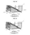
- FIG. 18 is an explanatory diagram of a design space according to a second example.
- FIG. 19 is an explanatory diagram of a method of generating an optimization block model according to the second example.
- FIG. 20 is an explanatory diagram illustrating the optimization block model generated according to the second example.
- FIG. 21A is an explanatory diagram illustrating a connected portion of the optimization block model generated according to the second example.
- FIG. 21B is a view of the optimization block model illustrated in FIG. 21A as viewed from a different angle.
- FIG. 22 is an explanatory diagram of a state where the optimization block model has been generated by the method of the first example as a comparative example for the method of generating the optimization block model according to the second example.
- FIG. 23A is a diagram illustrating a state of the optimization block model and connected portion according to the comparative example for the second example.
- FIG. 23B is a view of the optimization block model according to the comparative example illustrated in FIG. 23A as viewed from a different angle.
- FIG. 24 is an explanatory diagram illustrating setting of a design space in a method of generating an optimization block model according to a third example.
- FIG. 25A is an explanatory diagram illustrating the method of generating the optimization block model according to the third example.
- FIG. 25B is a view of the optimization block model illustrated in FIG. 25A as viewed from a different angle.
- an apparatus for analysis of shape optimization 1 is an apparatus that performs optimization calculation by numerical analysis of a shape of a portion of a structural body model 13 , of which an example is illustrated in FIG. 2 , formed by using a two-dimensional element, or the two-dimensional element and a three-dimensional element.
- the apparatus for analysis of shape optimization 1 is configured of a personal computer (PC), and has a display device 3 , an input device 5 , a memory storage 7 , a working data memory 9 , and an arithmetic processing unit 11 .
- PC personal computer
- the display device 3 , the input device 5 , the memory storage 7 , and the working data memory 9 are connected to the arithmetic processing unit 11 .
- the display device 3 , the input device 5 , the memory storage 7 , and the working data memory 9 perform their respective functions according to commands of the arithmetic processing unit 11 .
- the display device 3 is used in display of results of calculation and the like, and is configured of a liquid crystal monitor or the like.
- the input device 5 is used in instruction for display of a file of the structural body model 13 , input of conditions by an operator, and the like, and is configured of a key board, a mouse, and the like.
- the structural body model 13 may be configured of only two-dimensional elements, or may be configured of a combination of two-dimensional elements and three-dimensional elements.
- the structural body model 13 is formed of two-dimensional elements.
- the structural body model 13 is a block body formed of a casting such as an engine, for example, the structural body model 13 is formed of three-dimensional elements.
- the working data memory 9 has, inside thereof, a data storage area 9 a storing therein results of calculation, and a working area 9 b for performing calculation processing.
- the arithmetic processing unit 11 is configured of a central processing unit (CPU) of a personal computer (PC). Each unit of the arithmetic processing unit 11 described below is realized by the CPU executing a predetermined program.
- the arithmetic processing unit 11 is characterized in that the arithmetic processing unit 11 includes: a design space setting unit 15 that sets, as a design space 25 , a portion to be optimized, of which an example is illustrated in FIGS. 3A and 3B , in a part of the structural body model 13 ; an optimization block model generating unit 17 that generates, in the set design space 25 , an optimization block model 27 (see, for example, FIG.
- a connection processing unit 18 that performs processing of connecting the generated optimization block model 27 with the structural body model 13 ; a material property setting unit 19 that sets a material property for the optimization block model 27 ; a crashworthy optimum shaping condition setting unit 20 that sets a condition (referred to as “crashworthy optimum shaping condition”) for the structural body model 13 , the condition being for finding an optimum shape for a crashworthiness; a crashworthiness analysis condition setting unit 21 that sets a condition (referred to as “crashworthiness analysis condition”) for the optimization block model 27 (see FIG.
- a crashworthiness analysis unit 22 that executes, based on the set crashworthy optimum shaping condition and the crashworthiness analysis condition, the crashworthiness analysis on the optimization block model 27 ; a three-dimensional element necessity calculating unit 23 that calculates information related to necessity of each three-dimensional element for the crashworthiness of the optimization block model 27 when the crashworthiness analysis is performed; and an optimum shape determining unit 24 that determines, based on a result of the calculation, an optimum shape for the crashworthiness.
- a configuration of each of these units of the arithmetic processing unit 11 will be described in detail.
- the design space setting unit 15 sets, as the design space 25 , a portion to be optimized, in a part of the structural body model 13 .
- a portion around a B-pillar part on a right side of an automotive body is illustrated. In this example, this portion is the portion to be optimized.
- the design space setting unit 15 sets the design space 25 in that portion of the structural body model 13 , which specifically is the B-pillar portion illustrated in FIG. 2 .
- the design space 25 has been set in a part of the structural body model 13 by the design space setting unit 15 , as illustrated in FIGS. 3 A and 3 B, the portion of the structural body model 13 in that part is deleted and the deleted portion becomes the design space 25 .
- FIG. 3B illustrates a state where the design space 25 has been set, as viewed from an angle different from that in FIG. 3A .
- the apparatus for analysis of shape optimization 1 may be configured to set the design space 25 beforehand when the structural body model 13 is generated. If the design space 25 is set beforehand upon generation of the structural body model 13 , a generating unit itself that generates the structural body model 13 serves also as the design space setting unit 15 . That is, the design space setting unit 15 may have both of the above described function of setting the design space and the function of generating the structural body model 13 .
- the optimization block model generating unit 17 generates the optimization block model 27 to be subjected to analysis processing of optimization in the design space 25 set by the design space setting unit 15 , as illustrated in FIG. 4 .
- the optimization block model generating unit 17 may generate the optimization block model 27 in any shape of a size that fits in the design space 25 set in the portion of the structural body model 13 , as illustrated in FIGS. 3A and 3B .
- the optimization block model generating unit 17 forms the optimization block model 27 with three-dimensional elements.
- the optimization block model generating unit 17 preferably forms the three-dimensional elements, each with a three-dimensional element, which is a polyhedron having five sides or more and eight sides or less and which has at least one pair of sides parallel to each other.
- Reasons for this are as follows. If a part formed in the design space 25 is formed of a thin sheet like a part of an automotive body, an optimum shape of the optimization block model 27 is desirably calculated to be reflected in a structural body shape of the thin sheet, by executing calculation of optimization using the optimization block model 27 .
- the optimization block model 27 by forming the optimization block model 27 by using the three-dimensional elements, each of which is a polyhedron having five sides or more and eight sides or less and which has at least one pair of sides parallel to each other, such a demand becomes easier to be satisfied. Further, as the three-dimensional elements that form the optimization block model 27 and that are polyhedrons each having five sides or more, three-dimensional elements of a uniform size are preferably set to thereby increase accuracy of optimization.
- FIG. 4 illustrates the optimization block model 27 generated in an I-shape, which is an example. Further, the three-dimensional elements used to form the optimization block model 27 in this example are hexahedrons, as illustrated in FIGS. 5A and 5B .
- FIG. 5B is an enlarged view of a circled portion of the optimization block model 27 illustrated in FIG. 5A .
- FIG. 6 illustrates appearance of inside of the optimization block model 27 illustrated in FIG. 5A at around a quarter of its height.
- sizes of elements inside the optimization block model 27 are matched with sizes of elements at a surface of the optimization block model 27 .
- the sizes of the respective elements are uniform over the entire optimization block model 27 .
- the optimization block model generating unit 17 preferably generates the optimization block model 27 , along a peripheral surface where the design space 25 has been set in the structural body model 13 , and such that the three-dimensional elements are subdivided in parallel with a plane having the maximum area of the design space. For example, as illustrated in FIGS. 3A and 3B , if the B-pillar in the automotive body has been set as the design space 25 , the optimization block model generating unit 17 generates, as illustrated in FIG. 4 , the optimization block model 27 having the I-shape. A surface on the automobile's outer side of this optimization block model 27 has the largest area. The optimization block model generating unit 17 generates the optimization block model 27 such that the surface having this maximum area becomes parallel to a lateral surface of the automotive body.
- the connection processing unit 18 performs processing of connecting the generated optimization block model 27 with a structural body that is another portion of the automotive body, that is, a portion of the structural body model 13 , the portion being other than the optimization block model 27 .
- the connection processing unit 18 uses a rigid body element, a sheet element, or a beam element.
- the connection processing unit 18 preferably performs connection processing to reflect an original connected position between the portion deleted as the design space 25 and the structural body model 13 (automotive body), in a connected position between the optimization block model 27 and the above mentioned structural body, to accurately transmit a load from the structural body model 13 (automotive body) to the optimization block model 27 .
- FIG. 7A and 7B are diagrams illustrating a state where the connection processing between the optimization block model and the structural body model has been performed according to the first example.
- FIG. 7B is a view of the connected state between the optimization block model and the structural body model illustrated in FIG. 7A from a different angle.
- FIG. 7B illustrates, with white lines, a connected portion 29 between the optimization block model 27 and the structural body model 13 that have been connected together by the connection processing unit 18 .
- the material property setting unit 19 sets a material property such as a Young's modulus, a specific gravity, or a stress-strain curve representing yield strength and tensile strength, for the optimization block model 27 .
- a material property such as a Young's modulus, a specific gravity, or a stress-strain curve representing yield strength and tensile strength
- the material property setting unit 19 sets a Young's modulus of the three-dimensional elements of the optimization block model 27 to a Young's modulus lower than (for example, to be equal to or less than a half of) a Young's modulus of the two-dimensional element of this connected part.
- the material property setting unit 19 may set stress of a stress-strain curve of the three-dimensional elements of the optimization block model 27 to stress lower than stress of a stress-strain curve of the two-dimensional element of this connected part. As a result of this also, analysis that has no bias in deformation and that is well-balanced is able to be performed.
- the crashworthy optimum shaping condition setting unit 20 sets crashworthy optimum shaping conditions to find an optimum shape for the crashworthiness, for the optimization block model 27 .
- There are two types of the crashworthy optimum shaping conditions set by this crashworthy optimum shaping condition setting unit 20 which are objective conditions and constraint conditions.
- the objective condition is a condition set according to an object of the structural body model 13 . Examples of this objective condition include minimizing strain energy, minimizing generated stress, and maximizing absorbed energy.
- the crashworthy optimum shaping condition setting unit 20 sets only one objective condition for the optimization block model 27 .
- the constraint condition is a constraint imposed upon optimization analysis.
- Examples of the constraint condition include a material volume fraction, which is a volume ratio of the optimization block model 27 after optimization with respect to a volume of the optimization block model 27 before the optimization, and displacement of an arbitrary portion.
- the crashworthy optimum shaping condition setting unit 20 is able to set a plurality of constraint conditions for the optimization block model 27 .
- the crashworthiness analysis condition setting unit 21 sets crashworthiness analysis conditions to perform the crashworthiness analysis on the structural body model 13 that has been connected to the optimization block model 27 , the crashworthiness analysis conditions being a constrained position of the structural body model 13 , a position to which the crashworthiness load is applied, and the like. For example, if an analysis is performed when a bumper of another automobile collides with the B-pillar of the automotive body from the lateral side of the automotive body, the crashworthiness analysis condition setting unit 21 generates, as illustrated in FIG. 9 , a bumper model 28 corresponding to the bumper of the other automobile.
- the crashworthiness analysis condition setting unit 21 sets a condition to cause this generated bumper model 28 to collide, in a direction indicated with a white arrow in FIG. 8 , at a predetermined position of the optimization block model 27 (B-pillar) in a state of being fitted in the structural body model 13 , for example, at a position indicated with a white rectangle in FIG. 8 (see FIG. 9 ).
- the crashworthiness analysis condition setting unit 21 sets the structural body model 13 to be not constrained.
- the crashworthiness analysis condition setting unit 21 may be configured to perform crashworthiness analysis on the structural body model 13 beforehand and to set a load obtained as a result of the crashworthiness analysis as a crashworthiness load.
- the crashworthiness analysis unit 22 executes, based on the crashworthy optimum shaping conditions and the crashworthiness analysis conditions set as described above, the crashworthiness analysis on the optimization block model 27 .
- the crashworthiness analysis unit 22 uses the inertia relief method or dynamic explicit method.
- the inertia relief method is static analysis performed on something with the inertia force and the external load being balanced such as a structure floating in the air or a structure floating on the water.
- the dynamic explicit method is dynamic analysis performed by using a method of determining a physical quantity after passage of a predetermined time period based on a known physical quantity. Therefore, as the crashworthiness analysis unit 22 , commercially available analysis software using finite elements, for example, may be used.
- the three-dimensional element necessity calculating unit 23 calculates information related to necessity of each three-dimensional element in the optimization block model 27 when the crashworthiness analysis unit 22 performs the crashworthiness analysis. Examples of the information related to necessity of the respective three-dimensional elements include element densities of the respective three-dimensional elements.
- the three-dimensional element necessity calculating unit 23 calculates and sets the element densities of the respective three-dimensional elements of the optimization block model 27 to be 1.0 to 0.0. If the element density of a three-dimensional element is 1.0 for example, it means that the whole of this three-dimensional element is a material (necessary for the objective condition), and if the element density is 0.0, it means that a portion corresponding to this three-dimensional element is vacant (unnecessary).
- the three-dimensional element necessity calculating unit 23 executes the above described calculation process, information (for example, the element density of equal to or greater than 0.6) meaning “necessary” is calculated for three-dimensional elements satisfying given crashworthy optimum shaping conditions, these three dimensional elements being from the respective three-dimensional elements of the optimization block model 27 .
- the three-dimensional element necessity calculating unit 23 preferably performs discretization of an optimization parameter in optimization calculation by numerical analysis for a shape of a portion of the structural body model 13 .
- a penalty coefficient in this discretization is equal to or greater than “2”, or limitation is made to three to twenty times the size of the three-dimensional element that becomes a reference.
- the optimization parameter is able to be reflected in the structural body shape of the thin sheet.
- the three-dimensional element necessity calculating unit 23 may perform optimization calculation by topology optimization, that is, topology optimization processing, or optimization processing by any other calculation method, as optimization calculation by numerical analysis of a shape of a portion of the structural body model 13 .
- commercially available analysis software using finite elements is able to be used as the three-dimensional element necessity calculating unit 23 , for example.
- the optimum shape determining unit 24 determines, based on a result of calculation by the three-dimensional element necessity calculating unit 23 , an optimum shape for the crashworthiness. Specifically, the optimum shape determining unit 24 deletes, from the respective three-dimensional elements of the optimization block model 27 generated as described above, three dimensional elements (for example, three dimensional elements having an element density of less than 0.6) not satisfying the given crashworthy optimum shaping conditions, for example. By doing this, the optimum shape determining unit 24 leaves a shape of the optimization block model 27 formed only of the three-dimensional elements (for example, having an element density of equal to or greater than 0.6) satisfying the given crashworthy optimum shaping conditions, as its optimum shape.
- the optimum shape determining unit 24 may perform smoothing on the optimum shape thus obtained.
- the optimum shape determining unit 24 executing such optimization analysis processing, of the three-dimensional elements of the optimization block model 27 , the three-dimensional elements that form an optimum shape satisfying the given analysis conditions remain.
- a load is transmitted from the structural body model 13 to the optimization block model 27 via the connected portion 29 . That is, by the load being transmitted from the structural body model 13 to the optimization block model 27 , in the process of the optimization calculation, the optimization block model 27 is deformed and the direction of the load and the like are changed. When the direction of the load and the like are changed, load conditions such as the directions of the load are reflected in the optimization calculation such that an optimum shape is finally given.
- FIGS. 10A and 10B illustrate the I-shaped optimization block model 27 illustrated in FIG. 4 as a lone model, instead of being fitted in the design space 25 of the structural body model 13 .
- FIG. 10B is a view of the lone optimization block model illustrated in FIG. 10A as viewed from a different angle.
- FIGS. 11A and 11B illustrate a constrained portion 31 , which is a portion where a constraint condition has been set at the same position as the connected portion 29 illustrated in FIGS. 7A and 7B , with respect to the lone optimization block model 27 illustrated in FIGS. 10A and 10B .
- FIG. 10A and 10B illustrate the I-shaped optimization block model 27 illustrated in FIG. 4 as a lone model, instead of being fitted in the design space 25 of the structural body model 13 .
- FIG. 10B is a view of the lone optimization block model illustrated in FIG. 10A as viewed from a different angle.
- FIGS. 11A and 11B illustrate a constrained portion
- FIG. 11B is a view of the constrained state of the lone optimization block model illustrated in FIG. 11A as viewed from a different angle.
- FIG. 11A corresponds to FIG. 10A
- FIG. 11B corresponds to FIG. 10B .
- analysis of optimization processing was performed with the same analysis conditions as when the fitting into the structural body model 13 was performed as described above.
- the computer By input of operator instructions, through the input device 5 , a file of the structural body model 13 to be read out, the computer reads the structural body model 13 from the memory storage 7 to be displayed on the display device 3 (S 1 ). Next, the operator sets the design space 25 to be subjected to optimization processing, in the displayed structural body model 13 . Specifically, the operator specifies, by performing an input operation on the input device 5 , coordinates of a part to be the design space 25 in the structural body model 13 , and instructs an element of that part to be deleted. By this instruction, the design space setting unit 15 of the computer performs a process of deleting the element of the part to set the design space 25 (S 3 ).
- the operator instructs the optimization block model generating unit 17 to generate the optimization block model 27 of a size that fits in the design space 25 .
- This instruction includes an instruction on which plane in the design space 25 the optimization block model 27 is to be generated based on. For example, if the optimization block model 27 illustrated in FIGS. 4 and 5A is to be generated in the design space 25 of the structural body model 13 illustrated in FIGS. 3A and 3B , when an instruction to generate the optimization block model 27 with reference to a plane in a front-back direction of the optimization block model 27 is given, the optimization block model generating unit 17 of the computer generates the optimization block model 27 that is meshed by pushing out that plane in the front-back direction of the automotive body (S 5 ).
- the operator instructs the optimization block model 27 to connect to the structural body model 13 .
- This instruction includes which element of a rigid body element, a sheet element, or a beam element is to be used as a connection element.
- the connection processing unit 18 of the computer Upon receipt of the instruction, the connection processing unit 18 of the computer performs processing of connecting the optimization block model 27 with the structural body model 13 (S 7 ).
- the operator sets a material property of the optimization block model 27 (S 8 ).
- the operator performs an input operation on the input device 5 and inputs the material property such as a Young's modulus, a specific gravity, or a stress-strain property representing yield strength and tensile strength.
- the material property setting unit 19 of the computer sets the input material property for the optimization block model 27 that has been connected with the structural body model 13 as described above. Thereafter, the operator sets crashworthy optimum shaping conditions (S 9 ).
- the operator Upon this setting, the operator performs an input operation on the input device 5 and inputs, as the crashworthy optimum shaping conditions, an objective condition such as minimizing strain energy or maximizing absorbed energy and a constraint condition such as a material volume fraction, as described above.
- the crashworthy optimum shaping condition setting unit 20 of the computer sets these input crashworthy optimum shaping conditions for the optimization block model 27 .
- the operator sets the crashworthiness analysis conditions such as a collision object to be collided with the optimization block model 27 (for example, the bumper model 28 of another automobile as illustrated in FIG. 9 ) and a position to apply a crashworthiness load (S 10 ).
- the operator performs an input operation on the input device 5 and inputs the above described crashworthiness analysis conditions.
- the crashworthiness analysis condition setting unit 21 of the computer sets these input crashworthiness analysis conditions for the structural body model 13 , to which the optimization block model 27 has been connected as described above.
- the crashworthiness analysis unit 22 and three-dimensional element necessity calculating unit 23 of the computer execute, based on the set crashworthy optimum shaping conditions and the crashworthiness analysis conditions, the crashworthiness analysis on the optimization block model 27 , and finds information related to necessity of each three-dimensional element in the optimization block model 27 by calculation (S 11 ). That is, the crashworthiness analysis unit 22 of the computer executes the above described crashworthiness analysis on the optimization block model 27 .
- the three-dimensional element necessity calculating unit 23 of the computer calculates information related to necessity of each three-dimensional element in the optimization block model 27 upon this crashworthiness analysis.
- the optimum shape determining unit 24 of the computer determines, based on the information related to the necessity found as described above, an optimum shape of the optimization block model 27 for the crashworthiness (S 13 ).
- the operator generates a shape model obtained by the optimization calculation or the like and checks, based on that model, stiffness by other structural analysis calculation.
- the optimization block model 27 is generated in the set design space 25 , and the crashworthiness analysis is executed by connecting the optimization block model 27 with the structural body model 13 , load transmission from the connected portion 29 with the structural body model 13 to the optimization block model 27 is appropriately achieved and an optimum shape of the optimization block model 27 is able to be calculated accurately.
- optimization of an automotive body structure for example, is enabled, crash worthiness thereof is able to be improved, and weight reduction of a structural body such as an automotive body, is able to be realized, while maintaining crash performance of the structural body.
- FIGS. 5A and 5B have been exemplified as the three-dimensional elements forming the optimization block model 27 , and it has been described that the optimization block model 27 is preferably formed of three-dimensional elements, which are polyhedrons each having five or more sides and eight or less sides and which have at least one pair of sides parallel to each other, as other three-dimensional elements.
- this disclosure does not exclude a case where a tetrahedron as illustrated in FIGS. 13A and 13B is used as a three-dimensional element forming the optimization block model 27 .
- FIGS. 13A and 13B are explanatory diagrams illustrating another mode of the optimization block model according to the first example.
- FIG. 13A and 13B are explanatory diagrams illustrating another mode of the optimization block model according to the first example.
- FIG. 13A is a diagram illustrating an example of the other mode of the optimization block model according to the first example.
- FIG. 13B is an enlarged view illustrating a portion surrounded by a rectangle on the optimization block model illustrated in FIG. 13A with the portion being enlarged. If a tetrahedral element is used as a three-dimensional element forming the optimization block model 27 as illustrated in FIGS. 13A and 13B , model generation is possible by generating only an external form of the design space 25 and automatically filling in the inside thereof.
- the optimization block model 27 is difficult to be reflected in the structural body of the thin sheet.
- FIGS. 14A and 14B illustrate appearance of inside of the optimization block model 27 formed of tetrahedral elements at around a quarter of a height thereof.
- FIG. 14A illustrates appearance of inside of the optimization block model 27 generated such that the element sizes over the entire optimization block model 27 become uniform by matching the inside element size with the surface element size. By making the overall element size fine according to the surface element size, accurate analysis is able to be performed.
- the sizes of the elements forming the optimization block model 27 may not be uniform as described above.
- the optimization block model 27 may be generated such that the element size gradually becomes larger from the surface to the inside.
- FIG. 15 is a block diagram exemplifying a configuration of an apparatus for analysis of shape optimization according to a modified example of the first example.
- an apparatus for analysis of shape optimization 41 according to this modified example is configured to have, as illustrated in FIG.
- a stiffness optimum shaping condition setting unit 43 that sets a condition (referred to as “stiffness optimum shaping condition”) for the optimization block model 27 , the condition being to find an optimum shape for the stiffness; a stiffness analysis condition setting unit 45 that sets a condition (referred to as “stiffness analysis condition”) to perform a stiffness analysis on the structural body model 13 , to which the optimization block model 27 has been connected; and a stiffness analysis unit 47 that executes, based on the set stiffness optimum shaping condition and the stiffness analysis condition, the stiffness analysis on the optimization block model 27 .
- the same signs are appended to components that are the same as those of the apparatus for analysis of shape optimization 1 .
- examples of the stiffness optimum shaping condition include objective conditions and constraint conditions.
- Examples of the stiffness analysis condition include a load constraint condition.
- the stiffness optimum shaping condition setting unit 43 sets, similarly to the crashworthy optimum shaping condition setting unit 20 , an objective condition and a constraint condition input by the input device 5 , as stiffness optimum shaping conditions for the optimization block model 27 .
- this objective condition include maximizing the stiffness, minimizing the displacement, and minimizing the stress.
- this constraint condition include the material volume fraction and displacement of an arbitrary portion.
- the stiffness analysis condition setting unit 45 sets the load constraint condition input by the input device 5 , as a stiffness analysis condition, for the structural body model 13 , with which the optimization block model 27 has been connected. If, for example, the maximum stiffness of the optimization block model 27 for when a load to twist the structural body model 13 acts on the structural body model 13 is to be calculated, as illustrated in FIG. 16 , the stiffness analysis condition setting unit 45 sets four positions “a”, “b”, “c”, and “d” of the automotive body, which is an example of the structural body model 13 , and sets a condition for constraining three of these positions and applying a load to the remaining one position, as the load constraint condition of the structural body model 13 .
- the stiffness analysis unit 47 executes the stiffness analysis on the optimization block model 27 .
- the three-dimensional element necessity calculating unit 23 of the apparatus for analysis of shape optimization 41 according to this modified example has a function of calculating information related to necessity of each three-dimensional element of the optimization block model 27 for the crashworthiness and the stiffness thereof when the stiffness analysis unit 47 performs the stiffness analysis. Therefore, the three-dimensional element necessity calculating unit 23 according to this modified example respectively calculates information related to necessity of each three-dimensional element in the optimization block model 27 for both of when the crashworthiness analysis unit 22 performs the crashworthiness analysis and when the stiffness analysis unit 47 performs the stiffness analysis.
- the optimum shape determining unit 24 is configured to comprehensively determine, based on the information related to necessity of each three-dimensional element calculated when the crashworthiness analysis was performed and the information related to necessity of each three-dimensional element calculated when the stiffness analysis was performed, an optimum shape for the crashworthiness and the stiffness. For example, if the information related to necessity of each three-dimensional element is an element density of each three-dimensional element, the optimum shape determining unit 24 finds, per each three-dimensional element corresponding to the optimization block model 27 used in the crashworthiness analysis and per each three-dimensional element corresponding to the optimization block model 27 used in the stiffness analysis, an average value of the element density, and determines, based on the average value, an element to be deleted. As a result, the optimum shape determining unit 24 is able to determine, based on the result of the crashworthiness analysis and the result of the stiffness analysis, an overall optimum shape of the optimization block model 27 .
- Step S 1 to S 11 are the same as those described by using the flow chart of FIG. 12 , and thus description thereof will be omitted.
- material properties are set for the optimization block model 27 at Step S 8 , and thereafter, processing of Steps S 9 to S 11 is separately performed concurrently with later described processing of Steps S 21 to S 23 .
- the apparatus for analysis of shape optimization 41 of the computer sets a material property for the optimization block model 27 at Step S 8 , and thereafter sets stiffness optimum shaping conditions for finding an optimum shape for the stiffness, for the optimization block model 27 (S 21 ).
- the apparatus for analysis of shape optimization 41 sets a stiffness analysis condition for performing the stiffness analysis on the structural body model 13 , to which the optimization block model 27 has been connected (S 22 ).
- the apparatus for analysis of shape optimization 41 of the computer executes, based on the set stiffness optimum shaping conditions and the stiffness analysis condition, the stiffness analysis on the optimization block model 27 , and calculates information related to necessity of each three-dimensional element of the optimization block model 27 for the stiffness (S 23 ). Thereafter, the apparatus for analysis of shape optimization 41 determines, based on a result of the calculation of the three-dimensional element necessity calculation step found by performing the crashworthiness analysis at Step S 11 and a result of the calculation of the three-dimensional element necessity calculation step found by performing the stiffness analysis at Step S 23 , an optimum shape of the optimization block model 27 for the crashworthiness and the stiffness (S 24 ).
- the three-dimensional element necessity calculation step for a case where the stiffness analysis is executed which is Step S 23
- the stiffness analysis is performed on the structural body model 13 , to which the optimization block model 27 has been connected, and thus load transmission from the connected portion 29 with the structural body model 13 to the optimization block model 27 is properly achieved like the case for crashworthiness analysis. Therefore, information related to necessity of each three-dimensional element of the structural body model 13 is able to be calculated accurately with respect to both the crash worthiness and the stiffness. Therefore, an optimum shape determined based on this information is also accurate.
- This second example relates to another mode of the optimization block model generating unit 17 , and generation of an optimization block model is performed by: setting nodes in a connected portion with the two-dimensional elements or three-dimensional elements forming the structural body model 13 ; using hexahedral three-dimensional elements as the three-dimensional elements forming the optimization block model 27 ; and stacking the three-dimensional elements along a plane including the nodes set in the connected portion.
- generation of an optimization block model is performed by: setting nodes in a connected portion with the two-dimensional elements or three-dimensional elements forming the structural body model 13 ; using hexahedral three-dimensional elements as the three-dimensional elements forming the optimization block model 27 ; and stacking the three-dimensional elements along a plane including the nodes set in the connected portion.
- FIG. 18 illustrates a state where the design space 25 has been set in a portion of a rear side member of the structural body model 13 representing the automotive body.
- FIG. 18 in this example, what is not parallel with a reference axis plane exists at a connected position between the structural body model 13 formed of two-dimensional elements and three-dimensional elements of the optimization block model 27 illustrated in later described FIG. 20 .
- This second example is to be applied to such a case.
- the optimization block model generating unit 17 also has an optimization block model generating function described below, in addition to the above described optimization block model generating function according to the first example.
- the optimization block model generating unit 17 generates, as illustrated in FIG. 19 , a reference plane 33 that becomes a reference for generating the optimization block model 27 , with a sheet element, by joining with straight lines nodes present at a part where the structural body model 13 has been deleted on a lateral surface of the automotive body.
- the optimization block model generating unit 17 generates the optimization block model 27 by pushing out the reference plane 33 in the automobile's width direction to be integrated by node sharing.
- FIGS. 20, 21A, and 21B A state where the optimization block model 27 has been generated in this second example is illustrated in FIGS. 20, 21A, and 21B .
- FIG. 20 illustrates an enlarged view of the generated optimization block model 27 .
- FIGS. 21A and 21B illustrate the connected portion 29 in the optimization block model 27 .
- FIG. 21B illustrates the optimization block model 27 as viewed from an angle different from that in FIG. 21A .
- the optimization block model generating unit 17 generates the reference plane 33 and generates the optimization block model 27 by using this reference plane 33 .
- a connected state between the optimization block model 27 and the structural body model 13 becomes smooth, and as a result, an effect of load transmission between the optimization block model 27 and the structural body model 13 becoming accurate is achieved.
- FIGS. 22, 23A, and 23B As a comparative example for this second example, similarly to the first example, an example in which the optimization block model 27 has been generated without generating the reference plane 33 beforehand is illustrated in FIGS. 22, 23A, and 23B .
- FIG. 22 is an enlarged view of the optimization block model 27 generated in the comparative example.
- FIGS. 23A and 23B illustrate the connected portion 29 in the optimization block model 27 .
- FIG. 23B illustrates the optimization block model 27 of the comparative example as viewed from an angle different from that in FIG. 23A .
- steps 35 are formed in the slanted part and the optimization block model 27 and connected portion 29 of the comparative example are not smooth.
- the connected state between the optimization block model 27 and the structural body model 13 becomes smooth and, as a result, transmission of a load between the optimization block model 27 and the structural body model 13 becomes accurate.
- the optimization block model generating unit 17 may form the optimization block model 27 with a plurality of blocks formed of three-dimensional elements and generate the optimization block model 27 by connecting these plurality of blocks by using a rigid body element, a beam element, or a two-dimensional element.
- a process of generating the optimization block model 27 according to this third example will be described specifically.
- FIGS. 24, 25A, and 25B are explanatory diagrams of a method of generating the optimization block model according to this third example.
- FIG. 24 is an explanatory diagram illustrating a reference plane for optimization block model generation according to the third example.
- FIG. 25A is a diagram illustrating a state where the optimization block model according to the third example is generated.
- FIG. 25B is a view of the optimization block model illustrated in FIG. 25A as viewed from a different angle.
- the optimization block model generating unit 17 also has an optimization block model generating function according to this third example, in addition to the above described optimization block model generating functions according to the first and second examples.
- the optimization block model generating unit 17 uses the method of generating the reference plane 33 described in the second example and generates the optimization block model 27 with a plurality of blocks.
- the optimization block model generating unit 17 first generates a plurality of independent reference planes 33 a and 33 b in the design space 25 illustrated in FIG. 18 .
- the optimization block model generating unit 17 pushes out the upper and triangular reference plane 33 a illustrated in FIG. 24 in the front-back direction of the automobile to generate an upper block 27 a , which is a triangular prism portion as illustrated with a state A 1 of FIG. 25A .
- the optimization block model generating unit 17 pushes out the lower reference plane 33 b illustrated in FIG. 24 in the automobile's width direction to generate a lower block 27 b as illustrated with a state A 2 of FIG. 25A .
- the optimization block model generating unit 17 sequentially connects, with the connected portion 29 , the generated blocks together, as well as the optimization block model 27 and the structural body model 13 (automotive body) together, the optimization block model 27 being a connected body of these upper block 27 a and lower block 27 b (see a state A 3 of FIGS. 25A and 25B ).
- the optimization block model 27 is able to be generated, not only in the design space 25 formed of a block of a simple shape such as a cuboid, but also in the design space 25 , which is not of a simple shape, for example, the design space 25 formed of a block of a complex shape or a block including a slope.
- the optimization block model 27 is able to be formed with a smooth surface.
- the connection between the optimization block model 27 and the structural body model 13 is able to be made smooth and as a result, load transmission between the optimization block model 27 and the structural body model 13 is able to be achieved accurately.
- any of the upper block 27 a and lower block 27 b may be generated first, and the order of the connection between these blocks (the upper block 27 a and the lower block 27 b ) and the connection between the upper block 27 a or lower block 27 b with the automotive body is not particularly limited and any of these connections may be performed first.
- connection of blocks is preferably performed such that the connected area is equal to or less than 20%.
- a portion of the structural body model to be optimized is not limited to the B-pillar or rear side member of an automotive body, but may be a desired portion of an automotive body.
- a method and an apparatus for analysis of shape optimization may perform the process of setting the stiffness optimum shaping conditions, the process of setting the stiffness analysis condition, and the stiffness analysis processing, which are described in the modified example of the first example, to execute the process of calculating information related to necessity of each three-dimensional element of the optimization block model for the stiffness and the process of determining, based on a result of this calculation, an optimum shape for the stiffness, without performing the above described process of setting the crashworthy optimum shaping conditions, process of setting the crashworthiness analysis condition, and the crashworthiness analysis.
- the apparatus for analysis of shape optimization may not include the above described crashworthy optimum shaping condition setting unit, the crashworthiness analysis condition setting unit, and the crashworthiness analysis unit.
- the method and the apparatus for analysis of shape optimization may be those obtained by combining, as appropriate, the above described second and third examples with the modified example of the first example. Furthermore, all other examples, working examples, operation techniques, and the like made by those skilled in the art or the like based on the above described examples are included in this disclosure.
- a method and an apparatus for analysis of shape optimization are useful for optimization of a structural body such as an automotive body, and in particular are suitable for a method and an apparatus for analysis of shape optimization that realize both improvement in stiffness and crash worthiness of the structural body and weight reduction of the structural body.
Landscapes
- Engineering & Computer Science (AREA)
- Physics & Mathematics (AREA)
- Theoretical Computer Science (AREA)
- Geometry (AREA)
- General Physics & Mathematics (AREA)
- General Engineering & Computer Science (AREA)
- Computer Hardware Design (AREA)
- Evolutionary Computation (AREA)
- Aviation & Aerospace Engineering (AREA)
- Pure & Applied Mathematics (AREA)
- Mathematical Optimization (AREA)
- Mathematical Analysis (AREA)
- Computational Mathematics (AREA)
- Automation & Control Theory (AREA)
- Body Structure For Vehicles (AREA)
- Management, Administration, Business Operations System, And Electronic Commerce (AREA)
- Architecture (AREA)
- Software Systems (AREA)
- Shaping Metal By Deep-Drawing, Or The Like (AREA)
Applications Claiming Priority (3)
| Application Number | Priority Date | Filing Date | Title |
|---|---|---|---|
| JP2013018681A JP5585672B2 (ja) | 2013-02-01 | 2013-02-01 | 形状最適化解析方法及び装置 |
| JP2013-018681 | 2013-02-01 | ||
| PCT/JP2013/083936 WO2014119167A1 (ja) | 2013-02-01 | 2013-12-18 | 形状最適化解析(analysis of shape optimization)方法及び装置 |
Publications (2)
| Publication Number | Publication Date |
|---|---|
| US20150356237A1 US20150356237A1 (en) | 2015-12-10 |
| US10169497B2 true US10169497B2 (en) | 2019-01-01 |
Family
ID=51261892
Family Applications (1)
| Application Number | Title | Priority Date | Filing Date |
|---|---|---|---|
| US14/760,824 Active 2034-12-23 US10169497B2 (en) | 2013-02-01 | 2013-12-18 | Method and apparatus for analysis of shape optimization |
Country Status (7)
| Country | Link |
|---|---|
| US (1) | US10169497B2 (de) |
| EP (1) | EP2953040A4 (de) |
| JP (1) | JP5585672B2 (de) |
| KR (1) | KR101612690B1 (de) |
| CN (1) | CN104956369B (de) |
| MX (1) | MX345189B (de) |
| WO (1) | WO2014119167A1 (de) |
Cited By (1)
| Publication number | Priority date | Publication date | Assignee | Title |
|---|---|---|---|---|
| US11281819B2 (en) * | 2018-03-02 | 2022-03-22 | Autodesk, Inc. | Simplifying designs of mechanical assemblies via generative component consolidation |
Families Citing this family (19)
| Publication number | Priority date | Publication date | Assignee | Title |
|---|---|---|---|---|
| EP2763058B1 (de) * | 2013-01-30 | 2021-10-20 | Honda Research Institute Europe GmbH | Optimieren der Ausgestaltung von physikalischen Strukturen/Objekten |
| JP6544016B2 (ja) * | 2015-04-20 | 2019-07-17 | 株式会社豊田中央研究所 | 形状最適化解析装置、形状最適化解析方法、形状最適化解析プログラム |
| US10482202B2 (en) | 2016-06-30 | 2019-11-19 | The Procter & Gamble Company | Method for modeling a manufacturing process for a product |
| JP6222302B1 (ja) * | 2016-07-05 | 2017-11-01 | Jfeスチール株式会社 | 車体の接合位置の最適化解析方法及び装置 |
| JP6278087B1 (ja) * | 2016-10-04 | 2018-02-14 | Jfeスチール株式会社 | 車体の接合位置の最適化解析方法及び装置 |
| JP6583309B2 (ja) * | 2017-02-24 | 2019-10-02 | Jfeスチール株式会社 | 車体の補強部材の形状最適化方法及び装置 |
| JP6497426B1 (ja) | 2017-10-17 | 2019-04-10 | Jfeスチール株式会社 | 積層複合部材の形状最適化解析方法及び装置 |
| JP6590009B2 (ja) * | 2018-02-09 | 2019-10-16 | Jfeスチール株式会社 | 車体の接着位置の最適化解析方法及び装置 |
| JP6614301B1 (ja) * | 2018-09-14 | 2019-12-04 | Jfeスチール株式会社 | 車体の振動特性の適正化解析方法及び装置 |
| KR102286756B1 (ko) | 2019-02-26 | 2021-08-06 | 울산과학기술원 | 격자구조 생성 알고리즘을 이용한 설계방법 |
| EP3734477B1 (de) * | 2019-05-03 | 2023-03-29 | Honda Research Institute Europe GmbH | Verfahren zur strukturoptimierung von objekten unter verwendung eines deskriptors für deformationsmodi |
| US11604906B2 (en) * | 2019-09-17 | 2023-03-14 | Dassault Systemes Simulia Corp. | System and method for crashworthiness analytics in design |
| CN113204822B (zh) | 2021-05-17 | 2022-06-10 | 广州大学 | 一种将连续体拓扑优化结果转换为杆系结构的方法 |
| JP7820639B2 (ja) * | 2022-02-22 | 2026-02-26 | 日本製鉄株式会社 | 構造体設計支援装置、構造体設計支援方法及び構造体設計支援プログラム |
| JP7306510B1 (ja) | 2022-03-03 | 2023-07-11 | Jfeスチール株式会社 | 自動車の車体骨格部品における荷重伝達構造の最適化解析方法、装置及びプログラム、自動車の車体骨格部品における荷重伝達部材の製造方法 |
| JP7666427B2 (ja) | 2022-07-08 | 2025-04-22 | Jfeスチール株式会社 | 自動車車体設計方法、装置及びプログラム、並びに自動車車体の製造方法 |
| JP7493139B1 (ja) | 2023-02-09 | 2024-05-31 | Jfeスチール株式会社 | 自動車車体設計方法、装置及びプログラム、並びに自動車車体の製造方法 |
| JP7597174B1 (ja) | 2023-08-31 | 2024-12-10 | Jfeスチール株式会社 | 自動車部品の設計方法、装置及びプログラム、並びに自動車部品の製造方法 |
| WO2025071946A2 (en) * | 2023-09-28 | 2025-04-03 | Bennett Chandler | Method and apparatus used for biological control of agricultural pests |
Citations (10)
| Publication number | Priority date | Publication date | Assignee | Title |
|---|---|---|---|---|
| WO2006009026A1 (ja) | 2004-07-16 | 2006-01-26 | Kyoto University | 最適設計支援装置、最適設計支援方法及び最適設計支援プログラム |
| US20060259283A1 (en) * | 2005-04-15 | 2006-11-16 | Marc Brughmans | Method and system for dynamic analysis of complex systems |
| US20090164178A1 (en) * | 2007-12-21 | 2009-06-25 | Honda Motor Co., Ltd. | Crashworthiness design methodology using a hybrid cellular automata algorithm for the synthesis of topologies for structures subject to nonlinear transient loading |
| CN101504682A (zh) | 2009-03-20 | 2009-08-12 | 江苏申模数字化制造技术有限公司 | 基于cae结构分析的汽车主模型结构优化设计方法 |
| US20100153077A1 (en) * | 2008-12-12 | 2010-06-17 | Krishnan Suresh | Method And System For Analysis And Shape Optimization Of Physical Structures Using A Computerized Algebraic Dual Representation Implicit Dimensional Reduction |
| US20100262406A1 (en) * | 2009-04-10 | 2010-10-14 | Livermore Software Technology Corporation | Topology optimization for designing engineering product |
| JP2011257915A (ja) | 2010-06-08 | 2011-12-22 | Toyota Motor Corp | 設計支援装置および設計支援方法 |
| JP2013025533A (ja) | 2011-07-20 | 2013-02-04 | Jfe Steel Corp | 形状最適化解析方法及び装置 |
| US20140214370A1 (en) * | 2013-01-30 | 2014-07-31 | Honda Research Institute Europe Gmbh | Optimizing the design of physical structures/objects |
| CN104769592A (zh) | 2012-11-06 | 2015-07-08 | 杰富意钢铁株式会社 | 形状优化解析方法及装置 |
Family Cites Families (2)
| Publication number | Priority date | Publication date | Assignee | Title |
|---|---|---|---|---|
| JP2001297118A (ja) | 2000-04-14 | 2001-10-26 | Hitachi Ltd | 構造最適化方法および構造最適化装置 |
| JP2007179456A (ja) | 2005-12-28 | 2007-07-12 | Toyota Central Res & Dev Lab Inc | 機構構造物の設計装置および設計方法 |
-
2013
- 2013-02-01 JP JP2013018681A patent/JP5585672B2/ja active Active
- 2013-12-18 WO PCT/JP2013/083936 patent/WO2014119167A1/ja not_active Ceased
- 2013-12-18 MX MX2015009792A patent/MX345189B/es active IP Right Grant
- 2013-12-18 CN CN201380071921.0A patent/CN104956369B/zh active Active
- 2013-12-18 US US14/760,824 patent/US10169497B2/en active Active
- 2013-12-18 KR KR1020157020725A patent/KR101612690B1/ko active Active
- 2013-12-18 EP EP13873950.3A patent/EP2953040A4/de active Pending
Patent Citations (13)
| Publication number | Priority date | Publication date | Assignee | Title |
|---|---|---|---|---|
| WO2006009026A1 (ja) | 2004-07-16 | 2006-01-26 | Kyoto University | 最適設計支援装置、最適設計支援方法及び最適設計支援プログラム |
| US20070239411A1 (en) * | 2004-07-16 | 2007-10-11 | Kyoto University | Optimal Design Support System, Optical Design Support Method and Optimal Design Support Program |
| US20060259283A1 (en) * | 2005-04-15 | 2006-11-16 | Marc Brughmans | Method and system for dynamic analysis of complex systems |
| US20090164178A1 (en) * | 2007-12-21 | 2009-06-25 | Honda Motor Co., Ltd. | Crashworthiness design methodology using a hybrid cellular automata algorithm for the synthesis of topologies for structures subject to nonlinear transient loading |
| US20100153077A1 (en) * | 2008-12-12 | 2010-06-17 | Krishnan Suresh | Method And System For Analysis And Shape Optimization Of Physical Structures Using A Computerized Algebraic Dual Representation Implicit Dimensional Reduction |
| CN101504682A (zh) | 2009-03-20 | 2009-08-12 | 江苏申模数字化制造技术有限公司 | 基于cae结构分析的汽车主模型结构优化设计方法 |
| US20100262406A1 (en) * | 2009-04-10 | 2010-10-14 | Livermore Software Technology Corporation | Topology optimization for designing engineering product |
| JP2010250818A (ja) | 2009-04-10 | 2010-11-04 | Livermore Software Technology Corp | トポロジー最適化における工業製品の最適設計を得る方法 |
| JP2011257915A (ja) | 2010-06-08 | 2011-12-22 | Toyota Motor Corp | 設計支援装置および設計支援方法 |
| JP2013025533A (ja) | 2011-07-20 | 2013-02-04 | Jfe Steel Corp | 形状最適化解析方法及び装置 |
| CN104769592A (zh) | 2012-11-06 | 2015-07-08 | 杰富意钢铁株式会社 | 形状优化解析方法及装置 |
| US20150302641A1 (en) | 2012-11-06 | 2015-10-22 | Jfe Steel Corporation | Shape optimization analyzing method and apparatus therefor |
| US20140214370A1 (en) * | 2013-01-30 | 2014-07-31 | Honda Research Institute Europe Gmbh | Optimizing the design of physical structures/objects |
Non-Patent Citations (7)
| Title |
|---|
| Chinese Office Action dated Jun. 28, 2017, of corresponding Chinese Application No. 201380071921.0, along with a Search Report in English. |
| Kim, H., et al., "Crashworthiness Design and Evaluation on the Leading-cab Structure of Rolling Stock Using Topology Optimization," International Journal of Precision Engineering and Manufacturing, vol. 10, No. 2, Apr. 1, 2009, pp. 79-85. |
| Muller, O. et al., "Topology Optimization of Large Real World Structures", (online), Mar. 3, 2007, pp. 1-14, http://web.archive.org/web/20070303133506/http://www.ipek.uni-karlsruhe.de/medien/veroeffentlichungen/nafems99/nafems_paper.pdf. |
| Supplementary European Search Report dated Nov. 22, 2016, of corresponding European Application No. 13873950.3. |
| Wu, G., "Optimum Design for Crash Energy Absorption Ability of Car Front Side Member," Machine Design Research, vol. 27, No. 4, Aug. 31, 2011. |
| Yamada, T., "A topology optimization method based on the level set method incorporating a fictitious interface energy," Computer Methods in Applied Mechanics and Engineering, vol. 199, No. 45-48, Nov. 15, 2010. |
| Yuge, K. et al., "Design of Structural Members for Crashworthiness Using Three Dimensional Topology Optimization", Transactions of the Japan Society of Mechanical Engineers (Series A), Nov. 25, 2003, vol. 69, No. 687, pp. 93-100. |
Cited By (1)
| Publication number | Priority date | Publication date | Assignee | Title |
|---|---|---|---|---|
| US11281819B2 (en) * | 2018-03-02 | 2022-03-22 | Autodesk, Inc. | Simplifying designs of mechanical assemblies via generative component consolidation |
Also Published As
| Publication number | Publication date |
|---|---|
| EP2953040A4 (de) | 2016-12-21 |
| EP2953040A1 (de) | 2015-12-09 |
| CN104956369A (zh) | 2015-09-30 |
| JP5585672B2 (ja) | 2014-09-10 |
| WO2014119167A1 (ja) | 2014-08-07 |
| CN104956369B (zh) | 2018-07-17 |
| MX345189B (es) | 2017-01-20 |
| KR101612690B1 (ko) | 2016-04-26 |
| MX2015009792A (es) | 2015-10-29 |
| JP2014149733A (ja) | 2014-08-21 |
| US20150356237A1 (en) | 2015-12-10 |
| KR20150103374A (ko) | 2015-09-10 |
Similar Documents
| Publication | Publication Date | Title |
|---|---|---|
| US10169497B2 (en) | Method and apparatus for analysis of shape optimization | |
| US10073928B2 (en) | Method and device for analysis of shape optimization | |
| US9858714B2 (en) | Shape optimization analyzing method and apparatus therefor | |
| US20150168240A1 (en) | Method of identifying cause of springback and apparatus of identifying cause of springback | |
| JP5810702B2 (ja) | 形状最適化解析方法及び装置 | |
| Xie et al. | A variational formulation for vibro-acoustic analysis of a panel backed by an irregularly-bounded cavity | |
| CN110226161B (zh) | 车身增强构件的形状优化方法及形状优化装置 | |
| CN111226219B (zh) | 层叠复合构件的形状最优化解析方法及形状最优化解析装置 | |
| JP2020046185A (ja) | 車体の振動特性の適正化解析方法及び装置 | |
| CN107766683A (zh) | 一种厢式车车厢底部波纹横梁结构轻量化优化设计方法 | |
| JP6265811B2 (ja) | ドローモデル生成方法及びドローモデル生成システム | |
| JP6415835B2 (ja) | ドローモデル生成方法及びドローモデル生成システム | |
| JP6387661B2 (ja) | 構造体の剛性評価方法、装置、プログラム及びコンピュータ読み取り可能な記憶媒体 | |
| JP6144612B2 (ja) | ドローモデル生成方法及びドローモデル生成システム | |
| CN112036054A (zh) | 挤压铝合金梁结构性能的有限元计算方法及系统、介质 |
Legal Events
| Date | Code | Title | Description |
|---|---|---|---|
| AS | Assignment |
Owner name: JFE STEEL CORPORATION, JAPAN Free format text: ASSIGNMENT OF ASSIGNORS INTEREST;ASSIGNOR:SAITO, TAKANOBU;REEL/FRAME:036079/0917 Effective date: 20150518 |
|
| STCF | Information on status: patent grant |
Free format text: PATENTED CASE |
|
| MAFP | Maintenance fee payment |
Free format text: PAYMENT OF MAINTENANCE FEE, 4TH YEAR, LARGE ENTITY (ORIGINAL EVENT CODE: M1551); ENTITY STATUS OF PATENT OWNER: LARGE ENTITY Year of fee payment: 4 |