US10222168B2 - Trajectory adjustment structure of gun - Google Patents
Trajectory adjustment structure of gun Download PDFInfo
- Publication number
- US10222168B2 US10222168B2 US15/989,154 US201815989154A US10222168B2 US 10222168 B2 US10222168 B2 US 10222168B2 US 201815989154 A US201815989154 A US 201815989154A US 10222168 B2 US10222168 B2 US 10222168B2
- Authority
- US
- United States
- Prior art keywords
- adjustment
- gun barrel
- barrel
- transmission sleeve
- press
- Prior art date
- Legal status (The legal status is an assumption and is not a legal conclusion. Google has not performed a legal analysis and makes no representation as to the accuracy of the status listed.)
- Active
Links
Images




Classifications
-
- F—MECHANICAL ENGINEERING; LIGHTING; HEATING; WEAPONS; BLASTING
- F41—WEAPONS
- F41B—WEAPONS FOR PROJECTING MISSILES WITHOUT USE OF EXPLOSIVE OR COMBUSTIBLE PROPELLANT CHARGE; WEAPONS NOT OTHERWISE PROVIDED FOR
- F41B11/00—Compressed-gas guns, e.g. air guns; Steam guns
- F41B11/70—Details not provided for in F41B11/50 or F41B11/60
-
- F—MECHANICAL ENGINEERING; LIGHTING; HEATING; WEAPONS; BLASTING
- F41—WEAPONS
- F41A—FUNCTIONAL FEATURES OR DETAILS COMMON TO BOTH SMALLARMS AND ORDNANCE, e.g. CANNONS; MOUNTINGS FOR SMALLARMS OR ORDNANCE
- F41A21/00—Barrels; Gun tubes; Muzzle attachments; Barrel mounting means
- F41A21/10—Insert barrels, i.e. barrels for firing reduced calibre ammunition and being mounted within the normal barrels
-
- F—MECHANICAL ENGINEERING; LIGHTING; HEATING; WEAPONS; BLASTING
- F41—WEAPONS
- F41A—FUNCTIONAL FEATURES OR DETAILS COMMON TO BOTH SMALLARMS AND ORDNANCE, e.g. CANNONS; MOUNTINGS FOR SMALLARMS OR ORDNANCE
- F41A21/00—Barrels; Gun tubes; Muzzle attachments; Barrel mounting means
- F41A21/16—Barrels or gun tubes characterised by the shape of the bore
-
- F—MECHANICAL ENGINEERING; LIGHTING; HEATING; WEAPONS; BLASTING
- F41—WEAPONS
- F41B—WEAPONS FOR PROJECTING MISSILES WITHOUT USE OF EXPLOSIVE OR COMBUSTIBLE PROPELLANT CHARGE; WEAPONS NOT OTHERWISE PROVIDED FOR
- F41B11/00—Compressed-gas guns, e.g. air guns; Steam guns
- F41B11/80—Compressed-gas guns, e.g. air guns; Steam guns specially adapted for particular purposes
- F41B11/89—Compressed-gas guns, e.g. air guns; Steam guns specially adapted for particular purposes for toys
-
- F—MECHANICAL ENGINEERING; LIGHTING; HEATING; WEAPONS; BLASTING
- F41—WEAPONS
- F41B—WEAPONS FOR PROJECTING MISSILES WITHOUT USE OF EXPLOSIVE OR COMBUSTIBLE PROPELLANT CHARGE; WEAPONS NOT OTHERWISE PROVIDED FOR
- F41B7/00—Spring guns
- F41B7/08—Toy guns, i.e. guns launching objects of the gliding type, e.g. airplanes, parachute missiles
Definitions
- the present invention relates generally to a combination of a trajectory adjustment structure with a gun barrel to provide a trajectory adjustment structure that allows for stable and precise adjustment of a hop-up force applied to a projectile.
- a conventional hop-up adjustment mechanism is mounted outside the gun barrel and is fixed at a rear end part of the gun barrel.
- the hop-up adjustment mechanism must be removed first before the replacement can be conducted. It may occasionally occur that the replacement of gun barrel cannot be correctly carried out due to difference of design.
- the conventional hop-up adjustment mechanism involves an adjustment means that is rough and adjustment is often conducted with a pin or a rotary wheel such that each step of adjustment involves a significant change of the hop-up force, making it hard to control the precision of adjustment of a trajectory.
- a solution is provided for fine adjustment of the degree of hop-up of a projectile through depth of a downward stroke of a steel bead or other projection. Since this involves a fine adjustment operation with high precision, correction of trajectory may be conducted between successive shots and it is necessary to eliminate manual factors that cause instability, such as improving stability of holding gun and minimizing adjustment operation. However, the operation of adjustment would need sacrificing one hand for not holding the gun by moving the hand to the rear end of the gun barrel where the hop-up adjustment mechanism is located to conduct the adjustment. This would cause wobbling of the gun, and thus losing the significance of fine adjustment for trajectory.
- the primary objective of the present invention is to provide an adjustment assembly that allows for precise adjustment through an arrangement of thread sections in order to achieve the purpose of fine adjustment of a hop-up force to thereby help improve correction of trajectory and also allows a trajectory adjustment mechanism to be mounted inside a gun barrel to allow for easy replacement of the gun barrel, and also to help improve operation stability of adjustment through direct operation of the adjustment assembly that is mounted at a front end of the gun barrel.
- the present invention is mountable in a gun barrel and has a main structure that comprises: an adjustment assembly arranged at a front end of the gun barrel.
- the gun barrel is provided therein with a connection tube in abutting engagement with the adjustment assembly and is movable as being driven by the adjustment assembly.
- the adjustment assembly is formed thereon with a plurality of thread sections that are in threading engagement with the gun barrel for a fine adjustment operation of the adjustment assembly.
- the connection tube is provided, on one end thereof that is distant from the adjustment assembly, with at least one transmission sleeve.
- the transmission sleeve is provided, on one side thereof, with a press-down member, which is in abutting engagement with the transmission sleeve for being pressed inwardly of the gun barrel.
- a depth of the connection tube could be continuously changed as being slowly pushed such that the transmission sleeve arranged at an opposite end of the connection tube could slowly change a position of abutting engagement thereof with the press-down member to cause the press-down member to gradually press inwardly of the gun barrel to set an upper side of an inside wall of the gun barrel in a concave configuration that could provide a frictional force to a top of a BB bullet moving through the gun barrel so as to apply a hop-up or lifting force to the BB bullet, imposing a force of moving upward after being shot.
- a trajectory of the BB bullet could be changed in a precise manner. Due to the present invention being directly coupled in the gun barrel, replacement of the gun barrel
- the present invention provides a solution that overcomes such problems and achieves an advantage of improving utilization thereof.
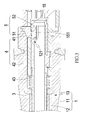
- FIG. 1 is a perspective view showing a preferred embodiment of the present invention.
- FIG. 2 is a cross-sectional view showing a front end part of a gun barrel of the present invention.
- FIG. 3 is a cross-sectional view showing a rear end part of a gun barrel of the present invention.
- FIG. 4 is a schematic view illustrating the structure of a press-down member and a flexible tube.
- FIG. 5 is a schematic view demonstrating adjustment conducted with the preferred embodiment of the present invention.
- FIG. 6 is another schematic view demonstrating adjustment conducted with the preferred embodiment of the present invention.
- FIG. 7 is a schematic view demonstrating transmission conducted with the preferred embodiment of the present invention.
- FIG. 8 is a schematic view demonstrating pressing conducted with the preferred embodiment of the present invention.
- FIG. 9 is another schematic view demonstrating transmission conducted with the preferred embodiment of the present invention.
- FIG. 10 is a schematic view demonstrating gun barrel replacement conducted with the preferred embodiment of the present invention.
- the present invention is mountable in mountable in a gun barrel 1 and the gun barrel 1 comprises an external barrel member 11 , an internal barrel member 12 arranged in the external barrel member 11 for a BB bullet to move therein, and at least one movement space 13 formed between the external barrel member 11 and the internal barrel member 12 .
- a main structure of the present invention comprises the following:
- an adjustment assembly 2 which is mounted to a front end of the gun barrel 1 , wherein the adjustment assembly 2 comprises an internal adjustment member 22 for driving the connection tube 3 that will be described below to move and an external adjustment member 14 is provided, as being screwed, between the external barrel member 11 and the internal adjustment member 22 ;
- At least one elastic element 143 having two ends respectively supported on and in engagement with the positioning projection 142 and an inside wall of the gun barrel 1 ;
- connection tube 3 arranged in the gun barrel 1 and abutting the adjustment assembly 2 to be driven by the adjustment assembly 2 to move;
- the transmission sleeve 4 comprises at least one abutting section 41 to abut a press-down member 5 that will be described below and at least one constraint section 42 that encloses the internal barrel member 12 and in engagement with an inside wall of the external barrel member 11 in order to allow the transmission sleeve 4 to move stably in a horizontal direction;
- a returning element 43 arranged in the movement space 13 and is coupled to the transmission sleeve 4 to cause the transmission sleeve 4 to move in a direction toward the connection tube 3 ;
- a press-down member 5 arranged at one side of the transmission sleeve 4 and abutted on by the transmission sleeve 4 to press inwardly of the gun barrel 1 ;
- a first curved surface section 52 formed on one side of the press-down member 5 that is opposite to the slope section 51 to provide abutting engagement, through a surface contact, with a BB bullet passing therethrough;
- a fixing assembly 6 arranged at a rear end of the gun barrel 1 to fix the transmission sleeve 4 and the press-down member 5 so as to allow the gun barrel 1 , the adjustment assembly 2 , and the connection tube 3 to detachably couple to a gun.
- the internal barrel member 12 comprises a notch section 121 , and the internal barrel member 12 is provided with a flexible tube 15 .
- the flexible tube 15 comprises a second curved surface section 151 formed at one side thereof corresponding to the notch section 121 and is abutted on by the press-down member 5 to provide abutting engagement, through a surface contact, with a BB bullet passing therethrough.
- the main structure of the present invention is mounted inside the gun barrel 1 to facilitate replacement of the gun barrel 1 by the user.
- the user when attempting to made an adjustment of the trajectory of BB bullets, may directly rotate the adjustment assembly 2 to abut on the connection tube 3 so as to drive the transmission sleeve 4 to move therewith, thereby making the press-down member 5 pressing inwardly of the gun barrel 1 , to achieve the purpose of adjusting a hop-up force.
- the positioning grooves 221 are arranged in a manner of being uniformly or equally angularly spacing around the outside circumferential wall of the internal adjustment member 22 at an interval of 30 degrees so that for each full turn that the user rotate the adjustment assembly 2 , an effect of positioning or indexing 12 positions may be provided.
- the connection tube 3 that encloses outside the internal barrel member 12 is driven to have an opposite end thereof to push, simultaneously or synchronously, the transmission sleeve 4 in a rearward direction (as shown in FIG. 7 ).
- the position that the abutting section 41 is set in engagement with or contacts the slope section 51 is continuously varied.
- the variation of such a position makes the press-down member 5 change the downward inclination angle thereof to as to press down in a direction toward deep interior of the gun barrel 1 . Due to the first curved surface section 52 formed on the bottom or lower side of the press-down member 5 , force can be uniformly applied to the flexible tube 15 arranged on the internal barrel member 12 .
- the flexible tube 15 is provided on an inner side thereof with the second curved surface section 151 , so that a BB bullet passing through the notch section 121 would be subjected to frictional engagement with the second curved surface section 151 to generate a hop-up force.
- the arrangement of the flexible tube 15 may be omitted and the first curved surface section 52 of the press-down member 5 may take the place thereof to provide such an operation.
- the frictional engagement thereof with the BB bullet is achieved though surface contact therebetween. This is different from the prior art in which contact is only made in the form of point contact, and could be of a significant stabilized hop-up effect and reduce potential risk of sideway spinning.
- the transmission sleeve 4 is also pushed or biased by the returning element 43 in a direction toward the connection tube 3 to keep the connection tube 3 in a condition of being in contact engagement with the internal adjustment member 22 (as shown in FIG. 2 ), so that the adjustment assembly 2 could be effectively operated by the user for any desired movement.
- the transmission sleeve 4 and the press-down member 5 are fixed by the fixing assembly 6 in an easy and simple manner, it only needs to release a fixing part 111 of the external barrel member 11 to withdraw the gun barrel 1 .
- the adjustment assembly 2 , the gun barrel 1 , and the connection tube 3 could be withdrawn and separated from the fixing assembly 6 , the transmission sleeve 4 , and the press-down member 5 so that replacement of the gun barrel 1 could be carried out easily.
Landscapes
- Engineering & Computer Science (AREA)
- General Engineering & Computer Science (AREA)
- Toys (AREA)
- Aiming, Guidance, Guns With A Light Source, Armor, Camouflage, And Targets (AREA)
Applications Claiming Priority (3)
| Application Number | Priority Date | Filing Date | Title |
|---|---|---|---|
| TW106210044U TWM556841U (zh) | 2017-07-07 | 2017-07-07 | 槍體彈道調整結構 |
| TW106210044 | 2017-07-07 | ||
| TW106210044U | 2017-07-07 |
Publications (2)
| Publication Number | Publication Date |
|---|---|
| US20190011217A1 US20190011217A1 (en) | 2019-01-10 |
| US10222168B2 true US10222168B2 (en) | 2019-03-05 |
Family
ID=62191637
Family Applications (1)
| Application Number | Title | Priority Date | Filing Date |
|---|---|---|---|
| US15/989,154 Active US10222168B2 (en) | 2017-07-07 | 2018-05-24 | Trajectory adjustment structure of gun |
Country Status (6)
| Country | Link |
|---|---|
| US (1) | US10222168B2 (fr) |
| ES (1) | ES1217468Y (fr) |
| FR (1) | FR3068775B3 (fr) |
| GB (1) | GB2564937B (fr) |
| HK (1) | HK1247521A2 (fr) |
| TW (1) | TWM556841U (fr) |
Cited By (1)
| Publication number | Priority date | Publication date | Assignee | Title |
|---|---|---|---|---|
| US11125529B2 (en) * | 2019-04-29 | 2021-09-21 | Sang su Yoon | Bullet decelerator for toy gun |
Families Citing this family (4)
| Publication number | Priority date | Publication date | Assignee | Title |
|---|---|---|---|---|
| CA3085332A1 (fr) * | 2017-12-08 | 2019-06-13 | James Eric Mcmillan | Ensemble canon de fusil concentrique |
| US20200141682A1 (en) * | 2017-12-08 | 2020-05-07 | James Eric McMillan | Concentric rifle barrel assembly |
| US12305954B2 (en) * | 2022-04-15 | 2025-05-20 | Moab Ventures Llc | Loading mechanism for an air gun |
| TWM653374U (zh) * | 2023-08-04 | 2024-04-01 | 怪怪貿易股份有限公司 | 玩具槍之調整裝置 |
Citations (6)
| Publication number | Priority date | Publication date | Assignee | Title |
|---|---|---|---|---|
| US5450838A (en) * | 1992-06-13 | 1995-09-19 | Nakahigashi; Masayuki | Gun barrel with means for insuring consistent projectile rotation of a discharged projectile |
| US5655510A (en) * | 1995-08-03 | 1997-08-12 | Western Arms | Model gun with trajectory control function |
| US7451756B2 (en) * | 1999-06-14 | 2008-11-18 | Tippmann Sports Llc | Paintball spin application method |
| US7603998B2 (en) * | 2005-06-30 | 2009-10-20 | Kee Action Sports I Llc | Barrel attachment for gas gun |
| US7775200B2 (en) * | 2005-05-23 | 2010-08-17 | Anderson Kenneth K | Barrel system for a paintball marker |
| US20140007857A1 (en) * | 2012-07-03 | 2014-01-09 | Erik K. Schlosser | Gas Powered Gun Barrel |
-
2017
- 2017-07-07 TW TW106210044U patent/TWM556841U/zh unknown
-
2018
- 2018-05-24 US US15/989,154 patent/US10222168B2/en active Active
- 2018-05-25 GB GB1808605.8A patent/GB2564937B/en active Active
- 2018-06-25 HK HK18108147.5A patent/HK1247521A2/zh unknown
- 2018-07-02 ES ES201831027U patent/ES1217468Y/es active Active
- 2018-07-05 FR FR1870806A patent/FR3068775B3/fr active Active
Patent Citations (6)
| Publication number | Priority date | Publication date | Assignee | Title |
|---|---|---|---|---|
| US5450838A (en) * | 1992-06-13 | 1995-09-19 | Nakahigashi; Masayuki | Gun barrel with means for insuring consistent projectile rotation of a discharged projectile |
| US5655510A (en) * | 1995-08-03 | 1997-08-12 | Western Arms | Model gun with trajectory control function |
| US7451756B2 (en) * | 1999-06-14 | 2008-11-18 | Tippmann Sports Llc | Paintball spin application method |
| US7775200B2 (en) * | 2005-05-23 | 2010-08-17 | Anderson Kenneth K | Barrel system for a paintball marker |
| US7603998B2 (en) * | 2005-06-30 | 2009-10-20 | Kee Action Sports I Llc | Barrel attachment for gas gun |
| US20140007857A1 (en) * | 2012-07-03 | 2014-01-09 | Erik K. Schlosser | Gas Powered Gun Barrel |
Cited By (1)
| Publication number | Priority date | Publication date | Assignee | Title |
|---|---|---|---|---|
| US11125529B2 (en) * | 2019-04-29 | 2021-09-21 | Sang su Yoon | Bullet decelerator for toy gun |
Also Published As
| Publication number | Publication date |
|---|---|
| GB2564937B (en) | 2020-08-12 |
| US20190011217A1 (en) | 2019-01-10 |
| FR3068775A3 (fr) | 2019-01-11 |
| GB2564937A (en) | 2019-01-30 |
| GB201808605D0 (en) | 2018-07-11 |
| FR3068775B3 (fr) | 2019-12-13 |
| HK1247521A2 (zh) | 2018-09-21 |
| ES1217468U8 (es) | 2018-12-12 |
| TWM556841U (zh) | 2018-03-11 |
| ES1217468U (es) | 2018-09-18 |
| ES1217468Y (es) | 2018-12-20 |
Similar Documents
| Publication | Publication Date | Title |
|---|---|---|
| US10222168B2 (en) | Trajectory adjustment structure of gun | |
| US9103624B1 (en) | Ballistic trajectory adjustment mechanism for toy gun | |
| US10352658B1 (en) | Rifle scope and mount system | |
| US20110173867A1 (en) | Adjustable support for firearms | |
| TWI583915B (zh) | 瞄準器 | |
| US12360355B2 (en) | Optical device and method of manufacturing tubular part-using product | |
| US11105579B2 (en) | Arrow rest assembly | |
| US9989331B2 (en) | Rotating connector for connecting the lower receiver of a rifle to the butt stock | |
| KR20160123009A (ko) | 도트 사이트 조준기 | |
| US10591253B1 (en) | Finger-adjustable scope adjustment mechanism | |
| JPS592886B2 (ja) | 銃用望遠照準器用レンズ移動機構及びパワ−調節機構 | |
| US3098410A (en) | Adjusting mechanism for recoilless rifle spotting barrel | |
| KR20070114377A (ko) | 소형 화기에 부품을 끼우기 위한 고정 시스템 및 그러한시스템을 포함하는 소형 화기 | |
| WO2021134629A1 (fr) | Mire de réglage fin de type ouvert | |
| US10670370B2 (en) | Laser sighting device | |
| JP7073585B2 (ja) | 光学機器の角度調整機構 | |
| US12510745B2 (en) | Toolless knob assembly for optical device | |
| CN110966891A (zh) | 一种开放式微调瞄具 | |
| US812376A (en) | Rifle-telescope. | |
| JP7693194B2 (ja) | 玩具銃、ホップ生成部およびホップアップ調整部 | |
| CN212227875U (zh) | 一种开放式微调瞄具 | |
| GB2569205A (en) | Laser sighting device | |
| TWI825436B (zh) | 補正機構(二) | |
| US2792632A (en) | Cam actuated sight | |
| CN208205927U (zh) | 一种瞄准镜的多功能调节支架 |
Legal Events
| Date | Code | Title | Description |
|---|---|---|---|
| FEPP | Fee payment procedure |
Free format text: ENTITY STATUS SET TO UNDISCOUNTED (ORIGINAL EVENT CODE: BIG.); ENTITY STATUS OF PATENT OWNER: SMALL ENTITY |
|
| AS | Assignment |
Owner name: GUAY GUAY TRADING CO., LTD., TAIWAN Free format text: ASSIGNMENT OF ASSIGNORS INTEREST;ASSIGNOR:LIAO, YIN-HSI;REEL/FRAME:045900/0030 Effective date: 20180522 |
|
| FEPP | Fee payment procedure |
Free format text: ENTITY STATUS SET TO SMALL (ORIGINAL EVENT CODE: SMAL); ENTITY STATUS OF PATENT OWNER: SMALL ENTITY |
|
| STCF | Information on status: patent grant |
Free format text: PATENTED CASE |
|
| MAFP | Maintenance fee payment |
Free format text: PAYMENT OF MAINTENANCE FEE, 4TH YR, SMALL ENTITY (ORIGINAL EVENT CODE: M2551); ENTITY STATUS OF PATENT OWNER: SMALL ENTITY Year of fee payment: 4 |