US10272585B1 - Tissue log saw conveyor with independent lane control cutting and variable conveyor flight length - Google Patents
Tissue log saw conveyor with independent lane control cutting and variable conveyor flight length Download PDFInfo
- Publication number
- US10272585B1 US10272585B1 US15/919,424 US201815919424A US10272585B1 US 10272585 B1 US10272585 B1 US 10272585B1 US 201815919424 A US201815919424 A US 201815919424A US 10272585 B1 US10272585 B1 US 10272585B1
- Authority
- US
- United States
- Prior art keywords
- lane
- log
- advancement member
- drive
- tissue
- Prior art date
- Legal status (The legal status is an assumption and is not a legal conclusion. Google has not performed a legal analysis and makes no representation as to the accuracy of the status listed.)
- Active
Links
Images




Classifications
-
- B—PERFORMING OPERATIONS; TRANSPORTING
- B26—HAND CUTTING TOOLS; CUTTING; SEVERING
- B26D—CUTTING; DETAILS COMMON TO MACHINES FOR PERFORATING, PUNCHING, CUTTING-OUT, STAMPING-OUT OR SEVERING
- B26D7/00—Details of apparatus for cutting, cutting-out, stamping-out, punching, perforating, or severing by means other than cutting
- B26D7/06—Arrangements for feeding or delivering work of other than sheet, web, or filamentary form
- B26D7/0625—Arrangements for feeding or delivering work of other than sheet, web, or filamentary form by endless conveyors, e.g. belts
-
- B—PERFORMING OPERATIONS; TRANSPORTING
- B26—HAND CUTTING TOOLS; CUTTING; SEVERING
- B26D—CUTTING; DETAILS COMMON TO MACHINES FOR PERFORATING, PUNCHING, CUTTING-OUT, STAMPING-OUT OR SEVERING
- B26D3/00—Cutting work characterised by the nature of the cut made; Apparatus therefor
- B26D3/16—Cutting rods or tubes transversely
-
- B—PERFORMING OPERATIONS; TRANSPORTING
- B26—HAND CUTTING TOOLS; CUTTING; SEVERING
- B26D—CUTTING; DETAILS COMMON TO MACHINES FOR PERFORATING, PUNCHING, CUTTING-OUT, STAMPING-OUT OR SEVERING
- B26D7/00—Details of apparatus for cutting, cutting-out, stamping-out, punching, perforating, or severing by means other than cutting
- B26D7/01—Means for holding or positioning work
-
- B—PERFORMING OPERATIONS; TRANSPORTING
- B26—HAND CUTTING TOOLS; CUTTING; SEVERING
- B26D—CUTTING; DETAILS COMMON TO MACHINES FOR PERFORATING, PUNCHING, CUTTING-OUT, STAMPING-OUT OR SEVERING
- B26D7/00—Details of apparatus for cutting, cutting-out, stamping-out, punching, perforating, or severing by means other than cutting
- B26D7/06—Arrangements for feeding or delivering work of other than sheet, web, or filamentary form
- B26D7/0683—Arrangements for feeding or delivering work of other than sheet, web, or filamentary form specially adapted for elongated articles
-
- B—PERFORMING OPERATIONS; TRANSPORTING
- B65—CONVEYING; PACKING; STORING; HANDLING THIN OR FILAMENTARY MATERIAL
- B65G—TRANSPORT OR STORAGE DEVICES, e.g. CONVEYORS FOR LOADING OR TIPPING, SHOP CONVEYOR SYSTEMS OR PNEUMATIC TUBE CONVEYORS
- B65G19/00—Conveyors comprising an impeller or a series of impellers carried by an endless traction element and arranged to move articles or materials over a supporting surface or underlying material, e.g. endless scraper conveyors
- B65G19/02—Conveyors comprising an impeller or a series of impellers carried by an endless traction element and arranged to move articles or materials over a supporting surface or underlying material, e.g. endless scraper conveyors for articles, e.g. for containers
-
- B—PERFORMING OPERATIONS; TRANSPORTING
- B65—CONVEYING; PACKING; STORING; HANDLING THIN OR FILAMENTARY MATERIAL
- B65G—TRANSPORT OR STORAGE DEVICES, e.g. CONVEYORS FOR LOADING OR TIPPING, SHOP CONVEYOR SYSTEMS OR PNEUMATIC TUBE CONVEYORS
- B65G19/00—Conveyors comprising an impeller or a series of impellers carried by an endless traction element and arranged to move articles or materials over a supporting surface or underlying material, e.g. endless scraper conveyors
- B65G19/18—Details
- B65G19/22—Impellers, e.g. push-plates, scrapers; Guiding means therefor
- B65G19/225—Impellers, e.g. push-plates, scrapers; Guiding means therefor for article conveyors, e.g. for container conveyors
-
- B—PERFORMING OPERATIONS; TRANSPORTING
- B65—CONVEYING; PACKING; STORING; HANDLING THIN OR FILAMENTARY MATERIAL
- B65G—TRANSPORT OR STORAGE DEVICES, e.g. CONVEYORS FOR LOADING OR TIPPING, SHOP CONVEYOR SYSTEMS OR PNEUMATIC TUBE CONVEYORS
- B65G47/00—Article or material-handling devices associated with conveyors; Methods employing such devices
- B65G47/22—Devices influencing the relative position or the attitude of articles during transit by conveyors
- B65G47/26—Devices influencing the relative position or the attitude of articles during transit by conveyors arranging the articles, e.g. varying spacing between individual articles
- B65G47/30—Devices influencing the relative position or the attitude of articles during transit by conveyors arranging the articles, e.g. varying spacing between individual articles during transit by a series of conveyors
- B65G47/31—Devices influencing the relative position or the attitude of articles during transit by conveyors arranging the articles, e.g. varying spacing between individual articles during transit by a series of conveyors by varying the relative speeds of the conveyors forming the series
-
- B—PERFORMING OPERATIONS; TRANSPORTING
- B26—HAND CUTTING TOOLS; CUTTING; SEVERING
- B26D—CUTTING; DETAILS COMMON TO MACHINES FOR PERFORATING, PUNCHING, CUTTING-OUT, STAMPING-OUT OR SEVERING
- B26D1/00—Cutting through work characterised by the nature or movement of the cutting member or particular materials not otherwise provided for; Apparatus or machines therefor; Cutting members therefor
- B26D1/01—Cutting through work characterised by the nature or movement of the cutting member or particular materials not otherwise provided for; Apparatus or machines therefor; Cutting members therefor involving a cutting member which does not travel with the work
- B26D1/12—Cutting through work characterised by the nature or movement of the cutting member or particular materials not otherwise provided for; Apparatus or machines therefor; Cutting members therefor involving a cutting member which does not travel with the work having a cutting member moving about an axis
- B26D1/14—Cutting through work characterised by the nature or movement of the cutting member or particular materials not otherwise provided for; Apparatus or machines therefor; Cutting members therefor involving a cutting member which does not travel with the work having a cutting member moving about an axis with a circular cutting member, e.g. disc cutter
- B26D1/157—Cutting through work characterised by the nature or movement of the cutting member or particular materials not otherwise provided for; Apparatus or machines therefor; Cutting members therefor involving a cutting member which does not travel with the work having a cutting member moving about an axis with a circular cutting member, e.g. disc cutter rotating about a movable axis
- B26D1/16—Cutting through work characterised by the nature or movement of the cutting member or particular materials not otherwise provided for; Apparatus or machines therefor; Cutting members therefor involving a cutting member which does not travel with the work having a cutting member moving about an axis with a circular cutting member, e.g. disc cutter rotating about a movable axis mounted on a movable arm or the like
-
- B—PERFORMING OPERATIONS; TRANSPORTING
- B26—HAND CUTTING TOOLS; CUTTING; SEVERING
- B26D—CUTTING; DETAILS COMMON TO MACHINES FOR PERFORATING, PUNCHING, CUTTING-OUT, STAMPING-OUT OR SEVERING
- B26D7/00—Details of apparatus for cutting, cutting-out, stamping-out, punching, perforating, or severing by means other than cutting
- B26D7/01—Means for holding or positioning work
- B26D2007/013—Means for holding or positioning work the work being tubes, rods or logs
Definitions
- the disclosure is directed to a conveyor for conveying tissue logs to a saw.
- the conveyor may have multiple lanes for conveying the tissue logs toward the log saw.
- the lanes may have log advancement members operatively connected to drives that are controlled by a controller.
- the controller may be configured to control the drives and move the log advancement members to advance the logs toward the log saw for cutting independently of one another.
- the conveyor has 4 lanes, and the log saw has a saw head with a rotary blade mounted on a cutting arm that orbits relative to the lanes.
- the tissue log placed in each lane is able to move independently relative to the adjacent lane.
- lane 1 may move independently from lane 2
- lane 2 may move independently from lane 3
- lane 3 may move independently from lane 4
- lane 4 may move independently from lane 1.
- successive tissue logs placed in the same lane may be moved independently within the same lane.
- FIG. 1 is a schematic drawing of a two lane conveyor and tissue saw as described herein.
- FIG. 2 is a partial perspective view of an end of a four lane conveyor as described herein.
- FIG. 3 is an end view of a lane of conveyor as described herein showing a log advancement member, a rail, and the continuous loops for the lane, and a portion of a peripheral constraint.
- FIG. 4 is an end view of a lane of conveyor as described herein showing a log advancement member and the continuous loops for the lane.
- FIG. 5 is a partial, perspective view of the log advancement members and the continuous loops for the lane.
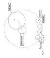
- FIG. 6 is a schematic drawing of a four lane conveyor and the orbiting cut cycle of the saw blade.
- FIG. 7 is a schematic drawing of the saw cut cycle when the log advancement members of all four lanes move together.
- FIG. 8 is a schematic drawing of the saw cut cycle when the log advancement members of all four lanes move independent of one another.
- FIG. 9 is a perspective view of an exemplary peripheral constraint.
- FIG. 10 is an end view of the peripheral constraint of FIG. 9 .
- FIG. 1 shows a conveyor system 20 for advancing tissue logs 22 , for instance, for cutting in a log saw 24 .
- the conveyor system 20 may include one lane 26 or have a plurality of lanes extending side by side.
- the lanes 26 may comprise a trough-like structure dimensioned to support the bottom and side surfaces of the tissue log 22 to be processed with an open top to allow the log to be deposited or received in the lane.
- the lane 26 may have a receiving end 28 and an opposite discharge end 30 and a length extending between the receiving end and the discharge end.
- the lane 26 may be configured to receive a tissue log 22 in the lane at the receiving end 28 of the lane.
- each lane may be configured to receive a tissue log from an accumulator 29 associated with a tissue winding machine.
- the accumulator 29 may be configured to release a number of logs into the available lanes of the conveyor.
- the lane 26 may be configured to discharge the tissue log 22 from the discharge end 30 of the lane.
- the discharge end 30 of the lane may be configured to expose tissue logs in the lane to a blade 32 of the log saw 24 .
- a gap 34 may be provided in lane adjacent to the discharge end 30 of the lane to allow the blade 32 of the log saw 24 to pass therethrough.
- the length of the lane may extend in a direction perpendicular to the cutting plane of the log saw.
- the lanes 26 may extend from a position to receive the tissue logs from the accumulator to a position beyond the log saw 24 so as to allow portions of the tissue log cut by the saw to be directed to a discharge conveyor for further processing.
- one lane may be provided. While the drawings show a log saw integrated with the conveyor system, the conveyor system may be stand-alone equipment that may be retrofitted or integrated with existing saw equipment.
- each lane 26 may be provided with at least one log advancement member 40 .
- the log advancement member 40 may comprise a paddle-like pusher configured to engage an axial end of the tissue log 22 at the receiving end 28 of the lane and push the tissue log toward the discharge end 30 of the lane and the log saw 24 with the axially opposite end of the tissue log passing through the path of the blade 32 of the log saw first.
- the log advancement member 40 may move between a starting position in which the log advancement member is positioned in the lane so as to allow the tissue log 22 to be received in the lane at the receiving end 28 of the lane from the upstream processing source, for instance, an accumulator, and a finish position in which the log advancement member advances the tissue log to the discharge end 30 of the lane and past the path of travel of the blade 32 of the log saw 24 across the lane, as applicable, so as to allow the last segment of the tissue log to be cut.
- the log advancement member 40 may engage the outer cylindrical surface of the tissue log in advancing the tissue log toward the saw. As will be described in more detail below, the log advancement member may advance the log in coordination with the travel of the blade.
- a drive 42 may be provided to move the log advancement member between the starting and finish position.
- One or more log advancement members 40 may be associated with a drive.
- the drive 42 may comprise a motor 44 and transmission 46 for rotating a continuous loop 48 on which one log advancement member 40 is connected.
- the drive may also comprise a motor and transmission for rotating a continuous loop on which two or more log advancement members are connected.
- the drive motor 44 may be a servo motor, and the transmission 46 may include a drive belt and a sprocket or wheel for driving the continuous loop 48 on which the log advancement member 40 is connected.
- a servo motor such as an Allen BradleyTM VPL series servo motor may be used.
- the continuous loop 48 may be a belt or a chain.
- Each lane 26 may be provided with two or more continuous loops 48 and two or more corresponding drives 42 with at least one log advancement member 40 fixed in position on each of the continuous loops.
- each lane may have at least two log advancement members, that is, at least a first log advancement member associated with the first continuous loop and drive of the lane, and at least a second log advancement member associated with the second continuous loop and drive of the lane.
- a log advancement member 40 may be connected to its continuous loop 48 in a manner to allow the other companion continuous loop to pass through its companion log advancement member in a given lane 26 .
- the log advancement member 40 may include side-by-side guides 50 , 52 dimensioned to accommodate the width of each continuous loop.
- the right side guide 52 of the right side log advancement member 40 ′ may have a loop connector 54 disposed in the guide 52 to allow the right side log advancement member to be connected to the right side continuous loop 48 ′.
- a like loop connector may be omitted in the left side guide 50 to allow the left side continuous loop 48 ′′ to pass through the right side log advancement member.
- FIG. 1 As shown in FIG.
- the left side guide 50 of the left side log advancement member 40 ′′ may have a loop connector 54 disposed in the guide 50 to allow the left side log advancement member to be connected to the left side continuous loop 48 ′′.
- the loop connector may be omitted from the right side guide 52 to allow the right side continuous loop 48 ′ to pass through the left side log advancement member 40 ′′.
- a standard log advancement member may be provided and fitted to either the left side continuous loop or the right side continuous loop by installing the loop connector in the desired guide as needed.
- the drive 42 for each continuous loop 48 may be mounted below the structure of the lane 26 .
- the drive sprocket or wheel 60 may be rotatably mounted at the end of the lane.
- the lane 26 may have a center rail 62 to support the log advancement member 40 as it travels in the lane.
- the continuous loops 48 may be arranged on either side of the center rail.
- the center axis of each log advancement member may be offset from its respective continuous loop so as to permit the log advancement member to travel in the center of the lane.
- the lane may have a channel 64 above the rail to accommodate the log advancement member as it travels in the lane.
- a controller 70 may be coupled to each drive 42 .
- the controller may comprise an Allen BradleyTM K5700 series servo drive.
- the controller 70 may be adapted and configured to control each drive 42 to initiate movement of the log advancement member 40 between the starting and finish positions.
- the controller 70 may be adapted and configured to control the drive 42 of the log advancement member 40 of one lane 26 independently of the log advancement member of another lane or to move the log advancement members of all of the lanes together simultaneously.
- the movement of the log advancement members 40 of the lanes 26 may be synchronized.
- the controller may also be adapted and configured to control the drive of the first log advancement member of each lane independently of the drive of the second log advancement member of each lane.
- the controller 70 may be configured to receive location signals from a position encoder on the drive 42 , the continuous loop 48 , or drive sprocket or wheel 60 , or proximity sensors on the lane 26 relative to the location of the log advancement member 40 , the status of the accumulator and the log saw. In response to the location signals, the controller 70 may be configured to control the drive to initiate movement of the log advancement member 40 as needed. For instance, once a tissue log 22 is received in the lane 26 , for instance, from the accumulator 29 , the controller may be configured to send a signal to the drive 42 to move the log advancement member 40 to the start position.
- the controller 70 may be configured to send signals to the drive 42 to intermittently advance the log advancement member 40 and the tissue log 22 toward the finish position.
- the signals may also be based upon positioning of the log saw 24 as the saw cycles through its cut.
- the signals may be a preprogrammed stepping or indexing of the log advancement member based on preselected parameters, including factors such as the saw cycle, tissue log segment length, tissue log size, number of active lanes, etc.
- the controller 70 may be configured to send signals to the drive 42 to rapidly move the log advancement member 40 to the starting position, once the log advancement member arrives at the finish position so as to be in position to advance the next or successive tissue log received in the lane.
- the controller 70 may be configured to send signals to the drive 42 to rapidly move the log advancement member 40 from the starting position to a position where a subsequent tissue log 22 received in the lane 26 is moved adjacent to a lead tissue log in the lane that is being advanced in the lane and/or cut with the saw.
- the controller 70 may be configured to send signals to the drive 42 of the lead tissue log advancement member 40 to dwell the lead tissue log advancement member at the finish position after the lead tissue log has completed processing and is discharged from the discharge end 30 of the lane.
- the controller 70 may be configured to also send signals to the successive tissue log advancement member 40 to advance the second tissue log toward the lead tissue log advancement member so the successive tissue log is held in position against the lead tissue log advancement member and the successive tissue log advancement member.
- the lead tissue log advancement member may engage the successive tissue log in the lane and support the free end of the successive tissue log during its initial sizing or face cut with the blade 32 of the log saw 24 , which may prevent a biased or skewed lead face on the successive tissue log.
- the controller 70 may be configured to move the lead tissue log advancement member to the start position at the receiving end of the lane to engage another tissue log received in the lane.
- the controller may be configured to initiate movement of the other log advancement to move the log to the discharge for cutting with the blade of the log saw.
- the controller may be configured to dwell the other log advancement member in the same manner as described previously to support the successive tissue log in the lane for its initial sizing or facing cut.
- the log advancement members may be configured to support a tissue log in both directions in the lane, e.g., advancement toward the discharge end of the lane and backwards toward the receiving end of the lane during the dwell cycle.
- FIGS. 6-8 provide schematic drawings of the cut cycle of an exemplary orbital saw 24 as it passes through a four lane conveyor, for instance, as shown in FIG. 2 .
- the log conveyor motion may be considered in two separate segments: (a) a “cutting” segment and (b) a “blade out-of-log” segment.
- one saw cutting head is shown. The concept may be applied to a saw with 2 or more lanes or a saw with any number or type of cutting head(s).
- the saw may be an orbital cutting saw, a plunge cutting saw, a band saw or a reciprocal saw.
- the blade cutting segment describes the portion of the cut cycle when the saw blade enters the lane and cuts the log.
- the blade cutting segment may begin when the blade 32 enters the lane 26 and may end when the blade has completed the cut of the tissue log 22 .
- the log and blade travel at the same velocity in the direction of log travel. Otherwise, the cut that is made on the tissue log will have a skew or bias on the cut-off tissue log segment.
- the controller 70 must control the drive 42 to maintain the log advancement member 40 and thus the tissue log 22 stationary during the blade cutting segment of the conveyor motion.
- a saw cutting head that has a component of velocity in the direction of log travel would have to match the velocity of the conveyed log in order not to have skew or bias to the cut.
- the saw blade 32 may still be in the lane 26 after completing the cut of the log 22 , and the controller may be configured to send signals to the drive 42 to advance the log advancement member, which may compress the log against the blade temporarily before the blade exits the lane.
- the blade cutting segment may begin when the blade 32 enters the lane 26 and end when the blade exits the lane.
- the blade out-of-log segment describes the portion of the cut cycle when the orbiting saw cutting blade 32 has completed cutting the log and moves to a position to begin cutting another log.
- the blade out-of-log segment may begin when the blade 32 has completed cutting the log 22 and may end when the blade enters the adjacent lane 26 to cut another log. Alternatively, the blade out-of-log segment may begin when the blade 32 has exited the lane 26 and may end when the blade enters the lane to cut another log.
- the logs in the lanes of the conveyor are free to move.
- This segment of the conveyor motion is typically used to advance the tissue log to a position corresponding to the desired length of the cut-off segment of the tissue log.
- the indexing or make-up distance is typically the distance that the log has to move before the next cut cycle occurs to achieve the desired cut-off length of the roll.
- the blade cutting segment is represented by the portion of the cut cycle when the leading edge of the blade first enters lane 1 and ends when the trailing edge of the blade exits lane 4.
- the blade out-of-log segment starts when the blade finishes the cut on the log of lane 4 and ends when the leading edge of the blade enters lane 1.
- the two segments together represent one cut cycle.
- each lane has its own blade in-log segment and blade out-of-log segment.
- lane 1's blade cutting segment is represented by the portion of the cut cycle when the leading edge of the blade first enters lane 1 and ends when the blade finishes the cut on the log of lane 1.
- the blade out-of-log segment for lane 1 is represented by the portion of the cut cycle when the blade finishes the cut on the log of lane 1 and ends when the leading edge of the blade reenters lane 1.
- the pattern is the same for each lane.
- the blade out-of-log segment for lane 2 is represented by the portion of the cut cycle when the blade finishes the cut on the log of lane 2 and ends when the leading edge of the blade reenters lane 2.
- each lane has a separate blade cutting segment and blade out-of-log segment.
- the FIG. 8 blade cutting segment represents a much smaller portion of the cut cycle compared to the FIG. 7 blade in-log segment.
- the FIG. 8 blade out-of-log segment represents a much greater portion of the cut cycle compared to the FIG. 7 blade out-of-log segment.
- indexing motion for all four lanes of the conveyor has to occur faster during the relatively small portion of the blade—out-of-log segment of the cycle. This tends to create more aggressive conveyor motion, which can be undesirable.
- the blade out-of-log segment for a lane is a relatively large portion of the cut cycle.
- the indexing motion for the lane may occur over a larger portion of the cut cycle. Consequently, the conveyor motion and lane motion may be relatively less aggressive. This may be advantageous depending upon the nature of the tissue log material.
- the saw cycle time may also be decreased (or throughput increased).
- each lane will have a different blade out-of-log segment and consequently, the cut-off segments of the tissue log will be discharged from the saw with a slight stagger.
- lane 1 will precede lane 2, which will precede lane 3 and so on.
- the controller 70 may be enabled to independently control the two drives 42 ′, 42 ′′ associated with each lane 26 , thus allowing time for the accumulator 29 to deposit a tissue log in the lane and a second log advancement member to move to the starting position and then advance the deposited tissue log immediately behind the first log advancement member advancing an in-process tissue log through the saw. This allows for an increase in throughput by eliminating space between successive tissue logs to be cut. It also better synchronizes timing with the accumulator 29 depositing a tissue log 22 in a lane 26 , and the log advancement member 40 being in the starting position.
- the controller 70 may be enabled to control the drives such that the distance between successive log advancement members may be changed as needed, for instance, to be increased to allow deposit of the tissue log from the accumulator, and to be decreased to eliminate any spacing between successive tissue logs in the lane.
- the controller may be enabled to control the drive to move the log advancement member so that the in-process flight or lead tissue log can move independently from the flight that is ready to accept a new log from the accumulator. With this, the timing of the log deposit from the accumulator to the lane may be more flexible.
- the controller While the controller is controlling the drive to move the log advancement member such that the in-process flight conveys a log through the saw to be cut, the controller is controlling the other drive to maintain the other log advancement member stationary so that the next flight can dwell waiting for the next log in the accumulator.
- the controller may be enabled to control the drive to move the log advancement member such that the front end of the log can be advanced to a position immediately behind the in-process log, thus eliminating spacing and otherwise unnecessary indexing and possible air cuts by the orbital saw.
- One or more of the lanes may also be provided with a peripheral constraint 80 , for instance, as shown in FIGS. 9 and 10 .
- the peripheral constraint 80 may engage the tissue log outer circumference or cylindrical surface area to help secure the tissue log 22 during cutting by the saw 24 .
- the peripheral constraint 80 may provide contact friction with the tissue log outer circumference or cylindrical surface thereby providing drag force on the tissue log to counter the force of acceleration and deceleration during the log indexing motion. The drag force assists with control of the tissue log advancement and provides accurate log advancement for each index or incremental advance.
- the peripheral log constraint may also be in accordance with U.S. Pat. No. 6,532,851 (the “'851 patent”), the disclosure of which is incorporated by reference, or a similar tissue log support and drag apparatus.
- right and left bottom support links 82 and right and left side support links 84 may be mounted to a lower support frame 86 .
- a push/pull rod 88 that is connected to a linkage 90 may be used to move the lower and side support links 82 , 84 as needed to accommodate varying product diameters.
- a flexible member 92 that conforms to the shape and size of the tissue log may be provided at the upper portion of the peripheral log constraint. The flexible member 92 may engage generally the top of the tissue log 22 in the lane 26 .
- the flexible member 92 for example, could be a thin, flexible sheet of plastic or rubber.
- the flexible member 92 may be attached to an upper frame member 94 , and the upper frame member may move up and down as needed to account for product of varying diameter.
- a top portion 96 and a bottom portion 98 of the flexible member 92 may be attached to the upper frame member 94 at different locations.
- the top portion 96 of the flexible member and the bottom portion 98 of the flexible member may be configured to move up and down at different rates, which in turn allows for the flexible member 92 to conform to the top outer surface of the tissue log for a wide range of product diameters.
Landscapes
- Engineering & Computer Science (AREA)
- Mechanical Engineering (AREA)
- Life Sciences & Earth Sciences (AREA)
- Forests & Forestry (AREA)
- Sawing (AREA)
- Replacement Of Web Rolls (AREA)
- Control Of Conveyors (AREA)
- Details Of Cutting Devices (AREA)
Priority Applications (7)
| Application Number | Priority Date | Filing Date | Title |
|---|---|---|---|
| US15/919,424 US10272585B1 (en) | 2017-10-11 | 2018-03-13 | Tissue log saw conveyor with independent lane control cutting and variable conveyor flight length |
| EP18715877.9A EP3694781B1 (fr) | 2017-10-11 | 2018-03-16 | Scie pour rouleaux de tissu avec convoyeur pour des rouleaux avec un controle indépendant pour des pistes et avec longueur variable des segments de convoyeur |
| CA3077156A CA3077156C (fr) | 2017-10-11 | 2018-03-16 | Transporteur a scie a rouleaux de tissu avec coupe a commande de piste independante et a longueur d'etendue de transporteur variable |
| BR112020007256-7A BR112020007256B1 (pt) | 2017-10-11 | 2018-03-16 | Transportador com serra para rolo de tecido com controle de corte independente na faixa e comprimento de percurso variável do transportador |
| MX2020003794A MX2020003794A (es) | 2017-10-11 | 2018-03-16 | Cinta transportadora de sierra de papel tisu con corte con control de carril independiente y longitud variable de listones de cinta transportadora. |
| PCT/US2018/022914 WO2019074539A1 (fr) | 2017-10-11 | 2018-03-16 | Transporteur à scie à rouleaux de tissu avec coupe à commande de piste indépendante et à longueur d'étendue de transporteur variable |
| US16/299,241 US10478988B2 (en) | 2017-10-11 | 2019-03-12 | Method of conveying tissue logs in a saw conveyor with independent lane control cutting and variable conveyor flight length |
Applications Claiming Priority (2)
| Application Number | Priority Date | Filing Date | Title |
|---|---|---|---|
| US201762570881P | 2017-10-11 | 2017-10-11 | |
| US15/919,424 US10272585B1 (en) | 2017-10-11 | 2018-03-13 | Tissue log saw conveyor with independent lane control cutting and variable conveyor flight length |
Related Child Applications (1)
| Application Number | Title | Priority Date | Filing Date |
|---|---|---|---|
| US16/299,241 Continuation US10478988B2 (en) | 2017-10-11 | 2019-03-12 | Method of conveying tissue logs in a saw conveyor with independent lane control cutting and variable conveyor flight length |
Publications (2)
| Publication Number | Publication Date |
|---|---|
| US20190105793A1 US20190105793A1 (en) | 2019-04-11 |
| US10272585B1 true US10272585B1 (en) | 2019-04-30 |
Family
ID=65992865
Family Applications (2)
| Application Number | Title | Priority Date | Filing Date |
|---|---|---|---|
| US15/919,424 Active US10272585B1 (en) | 2017-10-11 | 2018-03-13 | Tissue log saw conveyor with independent lane control cutting and variable conveyor flight length |
| US16/299,241 Active US10478988B2 (en) | 2017-10-11 | 2019-03-12 | Method of conveying tissue logs in a saw conveyor with independent lane control cutting and variable conveyor flight length |
Family Applications After (1)
| Application Number | Title | Priority Date | Filing Date |
|---|---|---|---|
| US16/299,241 Active US10478988B2 (en) | 2017-10-11 | 2019-03-12 | Method of conveying tissue logs in a saw conveyor with independent lane control cutting and variable conveyor flight length |
Country Status (5)
| Country | Link |
|---|---|
| US (2) | US10272585B1 (fr) |
| EP (1) | EP3694781B1 (fr) |
| CA (1) | CA3077156C (fr) |
| MX (1) | MX2020003794A (fr) |
| WO (1) | WO2019074539A1 (fr) |
Cited By (5)
| Publication number | Priority date | Publication date | Assignee | Title |
|---|---|---|---|---|
| US20190210237A1 (en) * | 2017-10-11 | 2019-07-11 | Paper Converting Machine Company | Method of Conveying Tissue Logs in a Saw Conveyor with Independent Lane Control Cutting and Variable Conveyor Flight Length |
| US20200002101A1 (en) * | 2018-06-29 | 2020-01-02 | William J. Morrisey, JR. | Indexing and auto-spacing system |
| WO2020112643A1 (fr) | 2018-11-30 | 2020-06-04 | Paper Converting Machine Company | Procédé de nettoyage de lame de scie à bûches |
| WO2021003093A1 (fr) * | 2019-07-02 | 2021-01-07 | Paper Converting Machine Company | Appareil pour supporter des rouleaux à enroulement droit de matériau de bande pendant la coupe |
| US20220088814A1 (en) * | 2019-02-27 | 2022-03-24 | Plusline S.R.L. | System and operating method for packaging paper rolls |
Families Citing this family (1)
| Publication number | Priority date | Publication date | Assignee | Title |
|---|---|---|---|---|
| CN110539346B (zh) * | 2019-09-12 | 2021-05-25 | 安徽省宣城市联通塑业有限责任公司 | 一种塑料制品管齐平切口的切割装置 |
Citations (18)
| Publication number | Priority date | Publication date | Assignee | Title |
|---|---|---|---|---|
| US4265361A (en) * | 1979-10-10 | 1981-05-05 | American Can Company | Apparatus for handling wound rolls of fibrous webs |
| US4552261A (en) * | 1983-12-27 | 1985-11-12 | Standard-Knapp, Inc. | Article grouper for case packer |
| US5127209A (en) * | 1990-11-15 | 1992-07-07 | Kimberly-Clark Corporation | Multi-purpose stacker with overlapping material handling devices |
| US5458033A (en) * | 1993-12-29 | 1995-10-17 | Paper Converting Machine Company | Trim eliminator for log saw |
| US5657615A (en) * | 1994-10-20 | 1997-08-19 | Riverwood International Corporation | Spacing conveyor mechanism |
| US5893701A (en) * | 1996-06-13 | 1999-04-13 | Food Machinery Sales, Inc. | Method and apparatus for forming groups of work products |
| US6532851B2 (en) | 2000-12-21 | 2003-03-18 | Paper Converting Machine Company | Apparatus for supporting product during cutting |
| US20060126522A1 (en) * | 2004-11-08 | 2006-06-15 | Du-Young Oh | Detecting malicious codes |
| US20090038458A1 (en) * | 2005-05-27 | 2009-02-12 | Fabio Perini S.P.A. | Cutting machine to cut rolls or logs of web material and relative method |
| US20090120256A1 (en) | 2007-10-22 | 2009-05-14 | Pasek James E | Food Article Feed Apparatus for a Food Article Slicing Machine |
| US20120297944A1 (en) | 2009-12-29 | 2012-11-29 | Fabio Perini S.P.A. | Machine for cutting web rolls |
| US20140110228A1 (en) * | 2010-12-30 | 2014-04-24 | Pulsar S.R.L. | Conveyor with adjustable lateral guides |
| US20150136564A1 (en) | 2012-06-19 | 2015-05-21 | Robert Bosch Gmbh | Feeding device for packaging machine |
| US20150298331A1 (en) | 2011-12-06 | 2015-10-22 | Paper Converting Machine Company | Method and apparatus for supporting product during cutting |
| US9309015B2 (en) * | 2014-06-30 | 2016-04-12 | The Procter & Gamble Company | Packaging equipment for rolled paper products |
| US20170320671A1 (en) * | 2016-05-05 | 2017-11-09 | Tissue Machinery Company S.P.A. | Device for distributing products in roll |
| US20180162006A1 (en) | 2016-12-09 | 2018-06-14 | The Procter & Gamble Company | Clamping device for machines used for transversally cutting convolutely wound logs of web materials |
| US20180162005A1 (en) | 2016-12-09 | 2018-06-14 | The Procter & Gamble Company | Device for transversally cutting convolutely wound logs of web materials |
Family Cites Families (1)
| Publication number | Priority date | Publication date | Assignee | Title |
|---|---|---|---|---|
| US10272585B1 (en) * | 2017-10-11 | 2019-04-30 | Paper Converting Machine Company | Tissue log saw conveyor with independent lane control cutting and variable conveyor flight length |
-
2018
- 2018-03-13 US US15/919,424 patent/US10272585B1/en active Active
- 2018-03-16 CA CA3077156A patent/CA3077156C/fr active Active
- 2018-03-16 WO PCT/US2018/022914 patent/WO2019074539A1/fr not_active Ceased
- 2018-03-16 MX MX2020003794A patent/MX2020003794A/es unknown
- 2018-03-16 EP EP18715877.9A patent/EP3694781B1/fr active Active
-
2019
- 2019-03-12 US US16/299,241 patent/US10478988B2/en active Active
Patent Citations (18)
| Publication number | Priority date | Publication date | Assignee | Title |
|---|---|---|---|---|
| US4265361A (en) * | 1979-10-10 | 1981-05-05 | American Can Company | Apparatus for handling wound rolls of fibrous webs |
| US4552261A (en) * | 1983-12-27 | 1985-11-12 | Standard-Knapp, Inc. | Article grouper for case packer |
| US5127209A (en) * | 1990-11-15 | 1992-07-07 | Kimberly-Clark Corporation | Multi-purpose stacker with overlapping material handling devices |
| US5458033A (en) * | 1993-12-29 | 1995-10-17 | Paper Converting Machine Company | Trim eliminator for log saw |
| US5657615A (en) * | 1994-10-20 | 1997-08-19 | Riverwood International Corporation | Spacing conveyor mechanism |
| US5893701A (en) * | 1996-06-13 | 1999-04-13 | Food Machinery Sales, Inc. | Method and apparatus for forming groups of work products |
| US6532851B2 (en) | 2000-12-21 | 2003-03-18 | Paper Converting Machine Company | Apparatus for supporting product during cutting |
| US20060126522A1 (en) * | 2004-11-08 | 2006-06-15 | Du-Young Oh | Detecting malicious codes |
| US20090038458A1 (en) * | 2005-05-27 | 2009-02-12 | Fabio Perini S.P.A. | Cutting machine to cut rolls or logs of web material and relative method |
| US20090120256A1 (en) | 2007-10-22 | 2009-05-14 | Pasek James E | Food Article Feed Apparatus for a Food Article Slicing Machine |
| US20120297944A1 (en) | 2009-12-29 | 2012-11-29 | Fabio Perini S.P.A. | Machine for cutting web rolls |
| US20140110228A1 (en) * | 2010-12-30 | 2014-04-24 | Pulsar S.R.L. | Conveyor with adjustable lateral guides |
| US20150298331A1 (en) | 2011-12-06 | 2015-10-22 | Paper Converting Machine Company | Method and apparatus for supporting product during cutting |
| US20150136564A1 (en) | 2012-06-19 | 2015-05-21 | Robert Bosch Gmbh | Feeding device for packaging machine |
| US9309015B2 (en) * | 2014-06-30 | 2016-04-12 | The Procter & Gamble Company | Packaging equipment for rolled paper products |
| US20170320671A1 (en) * | 2016-05-05 | 2017-11-09 | Tissue Machinery Company S.P.A. | Device for distributing products in roll |
| US20180162006A1 (en) | 2016-12-09 | 2018-06-14 | The Procter & Gamble Company | Clamping device for machines used for transversally cutting convolutely wound logs of web materials |
| US20180162005A1 (en) | 2016-12-09 | 2018-06-14 | The Procter & Gamble Company | Device for transversally cutting convolutely wound logs of web materials |
Non-Patent Citations (1)
| Title |
|---|
| International Search Report and Written Opinion for PCT/US2018/022914 dated Jul. 20, 2018. |
Cited By (9)
| Publication number | Priority date | Publication date | Assignee | Title |
|---|---|---|---|---|
| US20190210237A1 (en) * | 2017-10-11 | 2019-07-11 | Paper Converting Machine Company | Method of Conveying Tissue Logs in a Saw Conveyor with Independent Lane Control Cutting and Variable Conveyor Flight Length |
| US10478988B2 (en) * | 2017-10-11 | 2019-11-19 | Paper Converting Machine Company | Method of conveying tissue logs in a saw conveyor with independent lane control cutting and variable conveyor flight length |
| US20200002101A1 (en) * | 2018-06-29 | 2020-01-02 | William J. Morrisey, JR. | Indexing and auto-spacing system |
| US10919708B2 (en) * | 2018-06-29 | 2021-02-16 | Conflex Packaging, Inc. | Indexing and auto-spacing system |
| WO2020112643A1 (fr) | 2018-11-30 | 2020-06-04 | Paper Converting Machine Company | Procédé de nettoyage de lame de scie à bûches |
| US11571758B2 (en) | 2018-11-30 | 2023-02-07 | Paper Converting Machine Company | Method of cleaning blade of log saw |
| US20220088814A1 (en) * | 2019-02-27 | 2022-03-24 | Plusline S.R.L. | System and operating method for packaging paper rolls |
| WO2021003093A1 (fr) * | 2019-07-02 | 2021-01-07 | Paper Converting Machine Company | Appareil pour supporter des rouleaux à enroulement droit de matériau de bande pendant la coupe |
| US11447362B2 (en) | 2019-07-02 | 2022-09-20 | Paper Converting Machine Company | Apparatus for supporting convolutely wound logs of web material during cutting |
Also Published As
| Publication number | Publication date |
|---|---|
| BR112020007256A2 (pt) | 2020-10-13 |
| EP3694781B1 (fr) | 2026-04-22 |
| CA3077156A1 (fr) | 2019-04-18 |
| MX2020003794A (es) | 2020-08-03 |
| US10478988B2 (en) | 2019-11-19 |
| WO2019074539A1 (fr) | 2019-04-18 |
| CA3077156C (fr) | 2023-10-17 |
| EP3694781A1 (fr) | 2020-08-19 |
| US20190105793A1 (en) | 2019-04-11 |
| US20190210237A1 (en) | 2019-07-11 |
Similar Documents
| Publication | Publication Date | Title |
|---|---|---|
| US10272585B1 (en) | Tissue log saw conveyor with independent lane control cutting and variable conveyor flight length | |
| US9981400B2 (en) | Apparatus for slicing food products and method of providing intermediate sheets | |
| US9554581B2 (en) | Sausage collating device and method for collating sausages to form sausage groups | |
| CN103238913B (zh) | 用于分离产品的方法和设备 | |
| US4696464A (en) | Method of and an apparatus for uniting at least two streams of shingled laid out products, particularly folded paper products | |
| US3259029A (en) | Apparatus and process for making filter tips for cigarettes | |
| JP6516768B2 (ja) | 一つあるいは複数の生地シートから生地片のブランクを作るための方法および装置 | |
| CN102317185A (zh) | 用于已卷绕幅材的卷筒的上胶装置 | |
| US5230267A (en) | Food material decurling apparatus and method | |
| JP3210907B2 (ja) | ソーセージを切り離すための装置及びプロセス | |
| KR100392444B1 (ko) | 평형 제품을 이송하기 위한 장치 및 방법 | |
| JP7843669B2 (ja) | 相互に整列した食料品を伴う製品ストリームを製品基材上に提供するためのデバイスおよび方法 | |
| CN105858289B (zh) | 复卷机 | |
| CN113843828B (zh) | 分离装置 | |
| US5409340A (en) | Spine strip formation and feed method and apparatus | |
| US4750254A (en) | Continuously operating one-sided formatting and edge shaping machine | |
| JPH04275820A (ja) | チューブの切断機と切断方法 | |
| US4452118A (en) | Shake resaw machine | |
| RU2707044C2 (ru) | Способ транспортировки и устройство для транспортировки стержнеобразного изделия | |
| US11117283B2 (en) | Machine for cutting to size rolls of predefined length from logs with a greater length | |
| US5050724A (en) | Roll infeed conveyor | |
| US5950511A (en) | Process and device for handling printed products | |
| KR20180118147A (ko) | 담배, 필터 담배 또는 필터를 롤링하는 장치 및 방법 | |
| JP7146303B2 (ja) | スライス装置 | |
| EP0251802B1 (fr) | Mécanisme de coupe |
Legal Events
| Date | Code | Title | Description |
|---|---|---|---|
| AS | Assignment |
Owner name: PAPER CONVERTING MACHINE COMPANY, WISCONSIN Free format text: ASSIGNMENT OF ASSIGNORS INTEREST;ASSIGNORS:CHIKE, MATTHEW J.;GUSSERT, CORY P.;REEL/FRAME:045186/0036 Effective date: 20180307 |
|
| FEPP | Fee payment procedure |
Free format text: ENTITY STATUS SET TO UNDISCOUNTED (ORIGINAL EVENT CODE: BIG.); ENTITY STATUS OF PATENT OWNER: LARGE ENTITY |
|
| STCF | Information on status: patent grant |
Free format text: PATENTED CASE |
|
| MAFP | Maintenance fee payment |
Free format text: PAYMENT OF MAINTENANCE FEE, 4TH YEAR, LARGE ENTITY (ORIGINAL EVENT CODE: M1551); ENTITY STATUS OF PATENT OWNER: LARGE ENTITY Year of fee payment: 4 |
|
| AS | Assignment |
Owner name: BW CONVERTING, INC., WISCONSIN Free format text: CHANGE OF NAME;ASSIGNOR:PAPER CONVERTING MACHINE COMPANY;REEL/FRAME:068866/0798 Effective date: 20240819 |
|
| CC | Certificate of correction |