US10314075B2 - Multi-transceiver configuration method, multi-transceiver channel multiplexing method, and apparatus - Google Patents
Multi-transceiver configuration method, multi-transceiver channel multiplexing method, and apparatus Download PDFInfo
- Publication number
- US10314075B2 US10314075B2 US15/613,506 US201715613506A US10314075B2 US 10314075 B2 US10314075 B2 US 10314075B2 US 201715613506 A US201715613506 A US 201715613506A US 10314075 B2 US10314075 B2 US 10314075B2
- Authority
- US
- United States
- Prior art keywords
- sub
- channel
- sta
- mhz
- channels
- Prior art date
- Legal status (The legal status is an assumption and is not a legal conclusion. Google has not performed a legal analysis and makes no representation as to the accuracy of the status listed.)
- Active, expires
Links
- 238000000034 method Methods 0.000 title claims abstract description 74
- 238000012546 transfer Methods 0.000 claims abstract description 32
- 230000001174 ascending effect Effects 0.000 claims description 19
- 230000005540 biological transmission Effects 0.000 claims description 10
- 230000035945 sensitivity Effects 0.000 description 15
- 238000010586 diagram Methods 0.000 description 14
- 230000000694 effects Effects 0.000 description 6
- 230000002776 aggregation Effects 0.000 description 5
- 238000004220 aggregation Methods 0.000 description 5
- 230000003247 decreasing effect Effects 0.000 description 5
- 230000006835 compression Effects 0.000 description 4
- 238000007906 compression Methods 0.000 description 4
- 230000006872 improvement Effects 0.000 description 4
- 230000008569 process Effects 0.000 description 4
- 230000004044 response Effects 0.000 description 4
- 238000001228 spectrum Methods 0.000 description 4
- 238000004891 communication Methods 0.000 description 3
- 238000005457 optimization Methods 0.000 description 3
- OVGWMUWIRHGGJP-WVDJAODQSA-N (z)-7-[(1s,3r,4r,5s)-3-[(e,3r)-3-hydroxyoct-1-enyl]-6-thiabicyclo[3.1.1]heptan-4-yl]hept-5-enoic acid Chemical compound OC(=O)CCC\C=C/C[C@@H]1[C@@H](/C=C/[C@H](O)CCCCC)C[C@@H]2S[C@H]1C2 OVGWMUWIRHGGJP-WVDJAODQSA-N 0.000 description 2
- 238000009825 accumulation Methods 0.000 description 2
- 230000008859 change Effects 0.000 description 2
- 230000001934 delay Effects 0.000 description 2
- 238000011161 development Methods 0.000 description 2
- 238000005516 engineering process Methods 0.000 description 2
- 238000005498 polishing Methods 0.000 description 2
- 238000013459 approach Methods 0.000 description 1
- 230000006855 networking Effects 0.000 description 1
- 230000010363 phase shift Effects 0.000 description 1
- 238000012545 processing Methods 0.000 description 1
- 230000000750 progressive effect Effects 0.000 description 1
- 229920006395 saturated elastomer Polymers 0.000 description 1
- 238000012360 testing method Methods 0.000 description 1
Images


Classifications
-
- H—ELECTRICITY
- H04—ELECTRIC COMMUNICATION TECHNIQUE
- H04W—WIRELESS COMMUNICATION NETWORKS
- H04W74/00—Wireless channel access
- H04W74/04—Scheduled access
-
- H—ELECTRICITY
- H04—ELECTRIC COMMUNICATION TECHNIQUE
- H04L—TRANSMISSION OF DIGITAL INFORMATION, e.g. TELEGRAPHIC COMMUNICATION
- H04L5/00—Arrangements affording multiple use of the transmission path
- H04L5/003—Arrangements for allocating sub-channels of the transmission path
- H04L5/0037—Inter-user or inter-terminal allocation
-
- H—ELECTRICITY
- H04—ELECTRIC COMMUNICATION TECHNIQUE
- H04L—TRANSMISSION OF DIGITAL INFORMATION, e.g. TELEGRAPHIC COMMUNICATION
- H04L5/00—Arrangements affording multiple use of the transmission path
- H04L5/003—Arrangements for allocating sub-channels of the transmission path
- H04L5/0058—Allocation criteria
-
- H—ELECTRICITY
- H04—ELECTRIC COMMUNICATION TECHNIQUE
- H04L—TRANSMISSION OF DIGITAL INFORMATION, e.g. TELEGRAPHIC COMMUNICATION
- H04L5/00—Arrangements affording multiple use of the transmission path
- H04L5/003—Arrangements for allocating sub-channels of the transmission path
- H04L5/0058—Allocation criteria
- H04L5/006—Quality of the received signal, e.g. BER, SNR, water filling
-
- H—ELECTRICITY
- H04—ELECTRIC COMMUNICATION TECHNIQUE
- H04L—TRANSMISSION OF DIGITAL INFORMATION, e.g. TELEGRAPHIC COMMUNICATION
- H04L5/00—Arrangements affording multiple use of the transmission path
- H04L5/003—Arrangements for allocating sub-channels of the transmission path
- H04L5/0078—Timing of allocation
-
- H—ELECTRICITY
- H04—ELECTRIC COMMUNICATION TECHNIQUE
- H04W—WIRELESS COMMUNICATION NETWORKS
- H04W28/00—Network traffic management; Network resource management
- H04W28/02—Traffic management, e.g. flow control or congestion control
- H04W28/0231—Traffic management, e.g. flow control or congestion control based on communication conditions
- H04W28/0236—Traffic management, e.g. flow control or congestion control based on communication conditions radio quality, e.g. interference, losses or delay
-
- H—ELECTRICITY
- H04—ELECTRIC COMMUNICATION TECHNIQUE
- H04W—WIRELESS COMMUNICATION NETWORKS
- H04W28/00—Network traffic management; Network resource management
- H04W28/16—Central resource management; Negotiation of resources or communication parameters, e.g. negotiating bandwidth or QoS [Quality of Service]
-
- H—ELECTRICITY
- H04—ELECTRIC COMMUNICATION TECHNIQUE
- H04W—WIRELESS COMMUNICATION NETWORKS
- H04W72/00—Local resource management
-
- H04W72/042—
-
- H04W72/0426—
-
- H—ELECTRICITY
- H04—ELECTRIC COMMUNICATION TECHNIQUE
- H04W—WIRELESS COMMUNICATION NETWORKS
- H04W72/00—Local resource management
- H04W72/04—Wireless resource allocation
- H04W72/044—Wireless resource allocation based on the type of the allocated resource
- H04W72/0446—Resources in time domain, e.g. slots or frames
-
- H—ELECTRICITY
- H04—ELECTRIC COMMUNICATION TECHNIQUE
- H04W—WIRELESS COMMUNICATION NETWORKS
- H04W72/00—Local resource management
- H04W72/04—Wireless resource allocation
- H04W72/044—Wireless resource allocation based on the type of the allocated resource
- H04W72/0453—Resources in frequency domain, e.g. a carrier in FDMA
-
- H—ELECTRICITY
- H04—ELECTRIC COMMUNICATION TECHNIQUE
- H04W—WIRELESS COMMUNICATION NETWORKS
- H04W72/00—Local resource management
- H04W72/12—Wireless traffic scheduling
- H04W72/121—Wireless traffic scheduling for groups of terminals or users
-
- H04W72/1226—
-
- H—ELECTRICITY
- H04—ELECTRIC COMMUNICATION TECHNIQUE
- H04W—WIRELESS COMMUNICATION NETWORKS
- H04W72/00—Local resource management
- H04W72/12—Wireless traffic scheduling
- H04W72/1263—Mapping of traffic onto schedule, e.g. scheduled allocation or multiplexing of flows
-
- H—ELECTRICITY
- H04—ELECTRIC COMMUNICATION TECHNIQUE
- H04W—WIRELESS COMMUNICATION NETWORKS
- H04W72/00—Local resource management
- H04W72/20—Control channels or signalling for resource management
- H04W72/23—Control channels or signalling for resource management in the downlink direction of a wireless link, i.e. towards a terminal
-
- H—ELECTRICITY
- H04—ELECTRIC COMMUNICATION TECHNIQUE
- H04W—WIRELESS COMMUNICATION NETWORKS
- H04W72/00—Local resource management
- H04W72/20—Control channels or signalling for resource management
- H04W72/27—Control channels or signalling for resource management between access points
-
- H—ELECTRICITY
- H04—ELECTRIC COMMUNICATION TECHNIQUE
- H04W—WIRELESS COMMUNICATION NETWORKS
- H04W72/00—Local resource management
- H04W72/50—Allocation or scheduling criteria for wireless resources
- H04W72/54—Allocation or scheduling criteria for wireless resources based on quality criteria
-
- H—ELECTRICITY
- H04—ELECTRIC COMMUNICATION TECHNIQUE
- H04W—WIRELESS COMMUNICATION NETWORKS
- H04W74/00—Wireless channel access
- H04W74/002—Transmission of channel access control information
- H04W74/006—Transmission of channel access control information in the downlink, i.e. towards the terminal
-
- H—ELECTRICITY
- H04—ELECTRIC COMMUNICATION TECHNIQUE
- H04L—TRANSMISSION OF DIGITAL INFORMATION, e.g. TELEGRAPHIC COMMUNICATION
- H04L5/00—Arrangements affording multiple use of the transmission path
- H04L5/0001—Arrangements for dividing the transmission path
- H04L5/0003—Two-dimensional division
- H04L5/0005—Time-frequency
- H04L5/0007—Time-frequency the frequencies being orthogonal, e.g. OFDM(A) or DMT
-
- H—ELECTRICITY
- H04—ELECTRIC COMMUNICATION TECHNIQUE
- H04W—WIRELESS COMMUNICATION NETWORKS
- H04W84/00—Network topologies
- H04W84/02—Hierarchically pre-organised networks, e.g. paging networks, cellular networks, WLAN [Wireless Local Area Network] or WLL [Wireless Local Loop]
- H04W84/10—Small scale networks; Flat hierarchical networks
- H04W84/12—WLAN [Wireless Local Area Networks]
Definitions
- the present invention relates to the field of communications technologies, and in particular, to a multi-transceiver configuration method, a multi-transceiver channel multiplexing method, and an apparatus.
- a wireless video surveillance network is a specific application scenario of a wireless local area network designed for the Internet of Things.
- a frequency band from 779 MHz to 787 MHz of China is divided into eight 1-MHz channels, four 2-MHz channels, two 4-MHz channels, and one 8-MHz channel.
- a maximum channel bandwidth of a frequency band (the frequency band from 779 MHz to 787 MHz) of the Internet of Things lower than 1 GHz used for various control or sensor devices is only 8 MHz.
- a data rate of a high-definition video stream is relatively high. For example, in a high-definition video surveillance network, a data rate of a single terminal is 0.5 Mbps to 2.5 Mbps.
- an aggregation throughput of the wireless video surveillance network may reach 30 Mbps.
- high-definition video stream compression coding is classified into two coding manners: fixed bit rate compression and variable bit rate compression.
- variable bit rate compression coding a data rate is closely related to a change speed of monitored content, so that a video data rate presents an obvious dynamic change characteristic, thereby affecting network indicator parameters such as a throughput and a delay of the wireless video surveillance network.
- An AP (Access Point) of a video convergence center in the wireless video surveillance network is responsible for receiving video stream data uploaded by each STA in the network. Because a wavelength value corresponding to the frequency band from 779 MHz to 787 MHz is relatively large, a multi-antenna technology is generally not used in a device of the wireless video surveillance network due to a limitation on device outline dimensions.
- the AP performs, by using a single transceiver, networking on an 8-MHz channel according to the IEEE 802.11ah standard, due to a limited bandwidth, concurrently transmitting multiple high-definition video streams easily causes load of the network to reach a saturated state.
- a few STAs in the wireless video surveillance network can use only a QPSK (Quadrature Phase Shift Keying,) modulation manner, a data rate is only 1 ⁇ 4 of a data rate of 64-QAM (Quadrature Amplitude Modulation), and these low-rate STAs significantly decrease an average throughput of the network and increase an average delay.
- QPSK Quadrature Phase Shift Keying
- Embodiments of the present invention provide a multi-transceiver channel multiplexing method and an apparatus, so as to resolve a prior-art problem of a low throughput and a relatively high delay of a network.
- embodiments of the present invention provide a transceiver configuration method for an access point, applied to the Internet of Things, where a frequency band of the Internet of Things is divided into multiple sub-channel combinations including any combination of a 1-MHz sub-channel, a 2-MHz sub-channel, a 4-MHz sub-channel, and an 8-MHz sub-channel, and the Internet of Things corresponding to the access point includes N terminals STA i s, where 1 ⁇ i ⁇ N and N is a positive integer greater than 1.
- the method includes, for any STA i in the Internet of Things corresponding to the access point, obtaining, by the access point according to received signal quality information of the STA i , a maximum data transfer rate R i (n) of the STA i on each sub-channel n in a specified sub-channel combination; and obtaining, according to an average data volume needing to be sent by the STA i within a beacon period and R i (n), a channel access time T i (n) required by the STA i on the sub-channel n.
- the method also includes determining, by the access point according to an available access time T available (n) of each sub-channel n within the beacon period and T i (n) of the N STA i s, whether the specified sub-channel combination meets an allocation requirement of the N STA i s.
- a multi-transceiver channel multiplexing method includes sending, by an access point AP by using a transceiver configured on a sub-channel n, a channel allocation indication message to a terminal STA i allocated to the sub-channel n, where the channel allocation indication message includes a new modulation and coding scheme and scheduling information that correspond to the STA i , so that the STA i sends data according to the new modulation and coding scheme, and communicates, according to the scheduling information, with the transceiver on the sub-channel on which the STA i is located.
- a multi-transceiver channel multiplexing method includes receiving, by a terminal STA i , a channel allocation indication message delivered by an access point AP, where the channel allocation indication message includes a new modulation and coding scheme and scheduling information that correspond to the STA i .
- the method also includes sending, by the STA i , data according to the new modulation and coding scheme; switching to a target sub-channel according to a channel switching time included in the scheduling information; and communicating, according to a Media Access Control MAC address and an association identifier that are corresponding to the target sub-channel and that are of the access point, with a transceiver configured on the target sub-channel.
- an access point where a frequency band of the Internet of Things is divided into multiple sub-channel combinations including any combination of a 1-MHz sub-channel, a 2-MHz sub-channel, a 4-MHz sub-channel, and an 8-MHz sub-channel, and the Internet of Things corresponding to the access point includes N terminals STA i s, where 1 ⁇ i ⁇ N and N is a positive integer greater than 1.
- the apparatus includes: a memory and a processor, where the memory stores an executable instruction of the processor, and the processor executes the executable instruction to: for any STA i in the Internet of Things corresponding to the access point, obtain a maximum data transfer rate R i (n) of the STA i on each sub-channel n in a specified sub-channel combination according to received signal quality information of the STA i ; and obtain, according to an average data volume needing to be sent by the STA i within a beacon period and R i (n), a channel access time T i (n) required by the STA i on the sub-channel n; determine, according to an available access time T available (n) of each sub-channel n within the beacon period and T i (n) of the N STA i s, whether the specified sub-channel combination meets an allocation requirement of the N STA i s; and when it is determined that the specified sub-channel combination meets the allocation requirement of the N STA i s, configure at least one transcei
- an access point obtains R i (n) of a STA i on a sub-channel n in a specified sub-channel combination, and calculates T i (n) required by the STA i for transmitting an average data volume on the sub-channel n, and when the specified sub-channel combination manner meets an allocation requirement of N STA i s, the access point configures at least one transceiver for each sub-channel n in the specified sub-channel combination.
- Configuring multiple parallel transceivers on an access point side to implement parallel transmissions of the STA i s is equivalent to increasing channel access time.
- a data transfer rate of the STA can be increased generally. Therefore, by means of parallel running of multiple transceivers, a network throughput can be improved.
- FIG. 1 is a schematic structural diagram of a multi-transceiver wireless video surveillance aggregation network according to an embodiment of the present invention
- FIG. 2 is a schematic flowchart of a multi-transceiver configuration method according to an embodiment of the present invention
- FIG. 3 is a schematic flowchart of another multi-transceiver configuration method according to an embodiment of the present invention.
- FIG. 4 is a schematic diagram of a message format of a channel allocation indication message according to an embodiment of the present invention.
- FIG. 5 is a schematic diagram of a message format of an allocation field in the channel allocation indication message shown in FIG. 4 ;
- FIG. 6 is a schematic diagram of a message format of an allocation control field in the allocation field shown in FIG. 5 ;
- FIG. 7 is a flowchart of a multi-transceiver channel multiplexing method according to an embodiment of the present invention.
- FIG. 8 is a schematic structural diagram of an access point according to an embodiment of the present invention.
- FIG. 9 is a schematic structural diagram of another access point according to an embodiment of the present invention.
- FIG. 10 is a schematic structural diagram of a terminal according to an embodiment of the present invention.
- FIG. 11 is a schematic structural diagram of an access point according to an embodiment of the present invention.
- FIG. 12 is a schematic structural diagram of still another access point according to an embodiment of the present invention.
- embodiments of the present invention provide a multi-transceiver channel multiplexing method.
- an 8-MHz frequency band of the Internet of Things is divided into sub-channels whose bandwidths are smaller.
- An access point having multiple transceivers enables the transceivers to separately run on different sub-channels.
- Each transceiver correspondingly manages multiple STAs and receives video surveillance data sent by the multiple STAs. That is, the STAs on different sub-channels run in parallel in a frequency division multiplexing manner, and dividing the frequency band into sub-channels is equivalent to adding independent channels to implement parallel transmission, so as to increase a channel access time.
- the STA can correspondingly improve an MCS (Modulation and Coding Scheme) level and a data transfer rate. Therefore, the multi-transceiver channel multiplexing method provided in the embodiments of the present invention can improve a network throughput.
- MCS Modulation and Coding Scheme
- FIG. 1 is a schematic structural diagram of a multi-transceiver wireless video surveillance aggregation network according to an embodiment of the present invention.
- the wireless video surveillance aggregation network includes an access point AP of a video convergence center.
- the AP uses a structure of multiple transceivers.
- the transceivers run on multiple independent sub-channels in a frequency division multiplexing manner.
- Each transceiver may communicate with multiple STAs on a channel on which the transceiver is located, and each of the transceivers may use a single omnidirectional antenna, a single directional antenna, or multiple antennas.
- the AP collects video surveillance data of the multiple transceivers and then sends the collected video surveillance data to the video convergence center (a user end of video surveillance).
- the AP Before performing an embodiment of the multi-transceiver channel multiplexing method, the AP first divides an 8-MHz channel of a frequency band of the Internet of Things from 779 MHz to 787 MHz into sub-channel combinations, and the sub-channel combinations are stored locally according to an ascending order of a quantity of sub-channels. There are the following two types of combination manners:
- One type is the following nine sub-channel combination manners:
- the nine combination manners from (1) to (9) are arranged according to an ascending order of a quantity of sub-channels, and the AP may determine a specified sub-channel combination manner according to this order.
- the combination manner (1) is determined as the specified sub-channel combination at the first time; and if the combination manner (1) does not meet a requirement, the combination manner (2) is determined as the specified sub-channel combination at the second time, and the like.
- the other type is the following four sub-channel combination manners:
- the four combination manners from (I) to (IV) are also arranged according to an ascending order of a quantity of sub-channels, and the AP may determine the specified sub-channel combination manner according to this order.
- a frequency band from 470 MHz to 566 MHz and a frequency band from 614 MHz to 779 MHz may be further divided into multiple sub-channels whose bandwidths are 1 MHz.
- the multiple sub-channels whose bandwidths are 1 MHz and eight 1-MHz sub-channels of the frequency band from 779 MHz to 787 MHz together form a combination of more than eight 1-MHz sub-channels.
- the AP needs more than eight transceivers.
- the access point determines the specified sub-channel combination in sequence according to the foregoing order of the sub-channel combinations, and calculates whether the specified sub-channel combination meets a delay QoS requirement of each STA in the wireless video surveillance network and a network throughput of the entire network. For example, assuming that one 8-MHz channel does not meet the foregoing requirement, whether two 4-MHz sub-channels meet the foregoing requirement is determined according to the foregoing order of the sub-channel combinations.
- an 8-MHz channel is divided into eight 1-MHz sub-channels, and the AP configures eight transceivers, so that an obtained wireless video surveillance network can support a higher network throughput and accommodate more STAs.
- costs are correspondingly increased. Therefore, a problem of STA allocation on each sub-channel is changed to an optimization problem of using a minimum quantity of transceivers under the premise of ensuring a network throughput. In a specific optimization process, the following two conditions need to be met at the same time:
- R i (n) of the STA on the newly allocated sub-channel is greater than R i,QoS required by the STA.
- a sum of channel access time of all STAs to be allocated to each sub-channel n is not greater than an available access time T available (n) of the sub-channel n.
- the access point divides, according the foregoing order of the sub-channel combinations, the channel from 779 MHz to 787 MHz into sub-channels whose bandwidths are small.
- the existing wireless surveillance network is optimized according to the multi-transceiver configuration method provided in this embodiment of the present invention.
- FIG. 2 is a schematic flowchart of a multi-transceiver configuration method according to an embodiment of the present invention.
- the method is applied to an AP of the Internet of Things. It is assumed that a coverage area of the AP includes N STAs, and a STA i is used to represent any STA within the coverage area of the AP, where 1 ⁇ i ⁇ N, N is a quantity of STAs within the coverage area of the AP, and N is a positive integer greater than 1.
- the multi-transceiver configuration method includes the following steps.
- the AP obtains, according to received signal quality information of the STA i and an average data volume of the STA i within a beacon period, R i (n) of the STA i on each sub-channel n in a specified sub-channel combination and a channel access time T i (n) of the STA on the sub-channel n.
- the AP determines the specified sub-channel combination according to the foregoing order of (1) to (9) or (I) to (IV).
- the received signal quality information may include information about a received signal strength indicator (RSSI) of the STA i or information about a received signal-to-noise ratio of the STA i .
- RSSI received signal strength indicator
- the AP obtains received signal quality information of each STA i (for example, an RSSI of the STA i ).
- the AP already communicates with the STA, and in this application scenario, the AP can determine the RSSI of the STA according to a signal sent by the STA.
- the AP may perform signal testing on the STA or perform estimation by using a distance between the AP and the STA, to obtain the RSSI of the STA.
- the AP queries a table of minimum sensitivities of a receiver according to the RSSI of each STA i to obtain R i (n) of each STA i on the sub-channel n.
- a table of minimum sensitivities of a transceiver refer to related content in Table 1 to Table 3 in the following.
- the AP After obtaining R i (n) of the STA i on the sub-channel n, the AP obtains the channel access time T i (n) of the STA i on the sub-channel n according to the average data volume D i needing to be sent by the STA i within the beacon period and R i (n) of the STA i on the sub-channel n.
- R i,QoS is one of QoS (Quality of Service) parameters of the STA.
- the AP may obtain R i,QoS from a received latest TSPEC (Traffic Specification) element sent by the STA i , where the TSPEC element includes R i,QoS .
- TSPEC Traffic Specification
- the AP calculates, according to a formula 2, the channel access time T i (n) required by the STA i for transmitting D i on the sub-channel n:
- T i ⁇ ( n ) T BI * R i , QoS R i ⁇ ( n ) ( formula ⁇ ⁇ 2 )
- the AP determines, according to T available (n) of each sub-channel n and T i (n) of N STA i s, whether the specified sub-channel combination meets an allocation requirement of the N STA i s; and if the allocation requirement is met, perform step S 130 ; otherwise, perform step S 140 .
- step S 120 may include the following steps.
- the AP determines, according to T available (n) of each sub-channel n and T i (n) of each STA i , a STA i to be allocated to each sub-channel n.
- the STA i s may be allocated to each sub-channel one by one according to a descending order of bandwidths of sub-channels in the specified sub-channel combination.
- the STA i s may be allocated according to a descending order of R i (n) of the STA i s on the sub-channel n; or the STA i s may be allocated according to an ascending order of T i (n) required by the STA i s on the sub-channel n.
- the STA i s may be allocated to each sub-channel one by one according to an ascending order of bandwidths of sub-channels in the specified sub-channel combination.
- each STA i on a same sub-channel multiplexes the sub-channel in a time division manner, when the AP allocates the STA i s to each sub-channel, it must be ensured that a sum
- each STA i After allocating the STA i s to each sub-channel, each STA i sends data to the AP on the sub-channel of the STA i according to a bandwidth of the current sub-channel in a fixed bandwidth manner. For example, if a STA i is allocated to a 4-MHz sub-channel, the STA i always sends data to the AP by using a 4-MHz bandwidth.
- T available (n) of each sub-channel n is used and there is a STA i that is not allocated to any sub-channel, determine that the specified sub-channel combination does not meet the allocation requirement of the N STA i s.
- a new specified sub-channel combination is determined according to an ascending order of a quantity of sub-channels; and return to perform step S 110 .
- the new specified sub-channel combination meets the allocation requirement of the N STA i s, at least one transceiver is configured for each sub-channel, to which the STA i is allocated, in the new specified sub-channel combination.
- an access point obtains R i (n) of a STA i on a sub-channel n in a specified sub-channel combination, and calculates T i (n) required by the STA i for transmitting an average data volume on the sub-channel n, and when the specified sub-channel combination manner meets an allocation requirement of N STA i s, the access point configures at least one transceiver for each sub-channel n in the specified sub-channel combination.
- Configuring multiple parallel transceivers on an access point side to implement parallel transmissions of the STA i s is equivalent to increasing channel access time.
- a data transfer rate of the STA can be increased generally. Therefore, by means of parallel running of multiple transceivers, a network throughput can be improved.
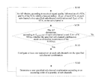
- FIG. 3 is a schematic flowchart of another transceiver configuration method according to an embodiment of the present invention. The method is applied to an AP of the Internet of Things. It is assumed that a coverage area of the AP includes N STAs, where N is a positive integer greater than 1.
- the AP determines a specified sub-channel combination according to an ascending order of a quantity of sub-channels and determines a target sub-channel according to a descending order of bandwidths of sub-channels n in the specified sub-channel combination.
- the specified sub-channel combination is determined according to the above-mentioned order of the sub-channel combination manners shown in (1) to (9) or (I) to (IV).
- the target sub-channel may be determined according to the descending order of the bandwidths of the sub-channels. Assuming that the specified sub-channel combination is one 4-MHz sub-channel and two 2-MHz sub-channels, first, the 4-MHz sub-channel is determined as the target sub-channel, then one of the two 2-MHz sub-channels is determined as a new target sub-channel, and finally, the other of the two 2-MHz sub-channels is determined as a new target sub-channel.
- S 220 The AP obtains R i (n) of a STA i on the target sub-channel according to received signal quality information of the STA i .
- S 230 The AP determines whether R i (n) of the STA i on the target sub-channel n is not less than R i,QoS of the STA i ; if yes, perform S 240 ; otherwise, return to perform S 210 , and determine a new specified sub-channel combination according to the ascending order of the quantity of sub-channels.
- R i (n) of the STA i on the target sub-channel n is not less than R i,QoS . Only in this way, a data transfer requirement of the STA i can be ensured, that is, the STA i may run on the sub-channel n. If R i (n) of the STA i on the sub-channel n is less than R i,QoS , it indicates that the STA i cannot run on the sub-channel n. Generally, a maximum data transfer rate R i (n) of a STA on a newly allocated sub-channel is greater than an average data transfer rate R i,QoS required by the STA.
- S 240 The AP obtains, according to D i needing to be sent by the STA i within a beacon period and R i (n), T i (n) required by the STA i on the target sub-channel.
- the AP determines, according to T i (n) required by each STA i on the target sub-channel n and T available (n) of the target sub-channel n, a STA i to be allocated to the target sub-channel n.
- S 260 The AP determines whether the N STAs are all allocated; if yes, perform S 270 ; and if not, determine a new target sub-channel in the specified sub-channel combination according to the descending order of the bandwidths of the sub-channels, then return to perform S 220 , and repeatedly perform steps S 220 to S 250 to determine STA i s to be allocated to the new target sub-channel until all terminals are allocated.
- a STA i to be allocated to the 4-MHz sub-channel is determined, if there is still a STA i that is not allocated, a STA i to be allocated to the 2-MHz sub-channel is determined according to the foregoing method until all STA i s are allocated.
- S 270 The AP determines whether a sum of channel access time of STA i s allocated to each sub-channel n in the specified sub-channel combination is not greater than T available (n) of the corresponding sub-channel n; if yes, perform S 280 ; and if a sum of channel access time of all STA i s allocated to at least one sub-channel in the specified sub-channel combination is greater than T available (n) of the sub-channel n, return to perform S 210 , and determine a next sub-channel combination as a new specified sub-channel combination.
- STA i s to be allocated to first several sub-channels in the specified sub-channel combination are determined, STA i s are allocated to a sub-channel according to T available (n) of the sub-channel, whether a sum of channel access time of the STA i s on the channel is not greater than T available (n) does not need to be repeatedly calculated, and only whether a sum of channel access time of all STA i s on a last sub-channel in the specified sub-channel combination is not greater than T available (n) needs to be calculated.
- the AP determines to use the specified sub-channel combination, and configures at least one transceiver on each sub-channel n in the specified sub-channel combination.
- a quantity of transceivers needing to be configured by the AP can be determined.
- the AP configures a transceiver for each sub-channel in the specified sub-channel combination.
- a standby transceiver may be further configured for a sub-channel. When a transceiver corresponding to the sub-channel is damaged, the standby transceiver is enabled, thereby ensuring uninterrupted communication of the STA i .
- no STA may be allocated to a sub-channel whose bandwidth is relatively small.
- the AP only needs to configure a transceiver for a sub-channel to which a STA is allocated, and does not need to configure a transceiver for the sub-channel to which no STA is allocated.
- step S 250 may be implemented in the following two manners.
- the STA i s may be allocated to the target sub-channel n one by one according to a descending order of R i (n) of the STA i s on the target sub-channel n, and when T available (n) of the target sub-channel n is used, all STA i s to run on the target sub-channel n are determined.
- R i (n) of the STA i s is arranged in a descending order, and a sum of T i (n) of first i STAs is calculated according to the order.
- T i (n) is greater than T available (n) of the target sub-channel n and a sum of T i (n) of first (i ⁇ 1) STAs is not greater than T available (n) of the target sub-channel n, it is determined that the first (i ⁇ 1) STAs are allocated to the target sub-channel n.
- a STA i having a relatively small maximum data transfer rate is preferentially allocated to a sub-channel whose bandwidth is relatively small to improve frequency spectrum usage of the network to a maximum extent, thereby meeting delay requirements of high-definition video streams of all STA i s.
- the AP may allocate the STA i s to the target sub-channel n one by one according to an ascending order of T i (n) of the STA i s on the target sub-channel n.
- T available (n) of the target sub-channel n is used, all STA i s to run on the target sub-channel n are determined.
- a STA i that needs a relatively long channel access time is preferentially allocated to a sub-channel whose bandwidth is relatively small, so that frequency spectrum usage of the network is improved to a maximum extent, thereby meeting delay requirements of high-definition video streams of all STA i s.
- the sum of channel access time of first i STA i s is calculated in a successive accumulation manner according to an ascending order of T i (n) of the STA i s on the target sub-channel n.
- a STA i that needs a relatively long channel access time is preferentially allocated to a sub-channel whose bandwidth is relatively small, so that frequency spectrum usage of a network is improved to a maximum extent, thereby meeting delay requirements of high-definition video streams of all STA i s.
- the rounded-down RSSIs are ⁇ 70 dBm, ⁇ 70 dBm, ⁇ 70 dBm, ⁇ 73 dBm, ⁇ 73 dBm, ⁇ 73 dBm, ⁇ 74 dBm, ⁇ 77 dBm, and ⁇ 81 dBm in sequence.
- MCS levels used by the 10 STA i s on the 8-MHz channel may be determined according to a table of minimum input sensitivities of a receiver shown in Table 1.
- Modulation scheme is a modulation and coding scheme.
- Bit rate is a bit rate of a modulation and coding scheme.
- Minimum input sensitivity (1-MHz PPDU) indicates a minimum input sensitivity on a 1-MHz sub-channel.
- Minimum input sensitivity (2-MHz PPDU) indicates a minimum input sensitivity on a 2-MHz sub-channel.
- Minimum input sensitivity (4-MHz PPDU) indicates a minimum input sensitivity on a 4-MHz sub-channel.
- Minimum input sensitivity (8-MHz PPDU) indicates a minimum input sensitivity on an 8-MHz sub-channel.
- PPDU indicates a physical layer convergence procedure (PLCP) protocol data unit.
- PLCP physical layer convergence procedure
- Table 2 shows correspondences between modulation and coding scheme levels on an 8-MHz sub-channel and corresponding data transfer rates.
- MCS ID indicates a number of a modulation and coding scheme.
- Modulation scheme indicates a modulation and coding scheme.
- Bit rate indicates a bit rate corresponding to a modulation and coding scheme.
- Data rate (Kbps) indicates a data transfer rate of a STAi on an 8-MHz sub-channel, and a unit symbol is Kbps.
- 8- ⁇ s Guard interval indicates that a guard interval in a modulation scheme is 8 ⁇ s; and 4- ⁇ s Guard interval indicates that a guard interval in a modulation scheme is 4 ⁇ s.
- Table 3 shows correspondences between modulation and coding scheme levels on a 4-MHz sub-channel and corresponding data transfer rates. Meanings of items in Table 3 are the same as those in Table 2, and details are not described herein again.
- STA i s to be allocated to the two 4-MHz sub-channels are determined.
- an embodiment of the present invention further provides an embodiment of a multi-transceiver channel multiplexing method.
- the method is applied to an AP.
- the AP determines, by using the multi-transceiver configuration method shown in FIG. 2 or FIG. 3 , a quantity of transceivers that need to be configured by the AP.
- the AP needs to notify each STA i of a sub-channel on which the STA i is to run and a modulation and coding scheme to be used by the STA i .
- the multi-transceiver channel multiplexing method includes the following.
- the AP sends, by using a transceiver configured on each sub-channel, a channel allocation indication message to a STA i allocated to the sub-channel.
- the channel allocation indication message includes information about the sub-channel allocated to the STA i and scheduling information, so that the STA i communicates, according to the information about the sub-channel and the scheduling information, with the transceiver on the sub-channel on which the STA i is located.
- Each STA i sends data to the AP only on the sub-channel of the STA i in a fixed bandwidth manner according to a bandwidth of the current sub-channel.
- the AP After determining a STA i allocation status on each sub-channel, the AP sends a channel allocation indication message to a STA i , to notify, by using the channel allocation indication message, the STA i of information about a sub-channel allocated to the STA i and scheduling information.
- the information about the sub-channel includes a modulation and coding scheme needing to be used by the STA i .
- the channel allocation indication message may be an information element, and the information element needs to be inserted into another message to be sent to the STA i .
- the channel allocation indication message may be an independent message that may be independently sent by the AP to the STA i .
- FIG. 4 is a schematic diagram of a data message format when a channel allocation indication message is an information element.
- the channel allocation indication message includes: an element ID, a length, an allocation field 1 , an allocation field 2 , . . . , and an allocation field N.
- the length indicates a length of the channel allocation indication message
- the allocation field indicates information about a sub-channel allocated by an AP to a STA i .
- the channel allocation indication message also includes channel allocation information of all STAs within a coverage area of the AP, and is sent to each STA i in a broadcast manner.
- FIG. 5 shows a message format of each allocation field in a channel allocation indication message.
- the allocation field includes a new modulation and coding scheme and scheduling information controlling a STA i to switch a channel.
- the allocation field includes: an allocation control field, a STA AID (Association Identifier), a new channel number, a new STA AID, a new AP MAC (Media Access Control) address, a new AP AID, a new MCS number, and a channel switching count.
- the allocation control field is a control field of the allocation field in the channel allocation indication message;
- the STA AID is an AID of a STA;
- the new channel number is a number of a new sub-channel allocated by an AP to a STA;
- the new STA AID is an AID reallocated by the AP to the STA;
- the new AP MAC address is a MAC address of a transceiver corresponding to the new sub-channel allocated to the STA, where multiple transceivers are configured for an AP, and different transceivers correspond to different MAC addresses;
- the new AP AID is an AID of the transceiver corresponding to the new sub-channel allocated to the STA;
- the new MCS number is a number of a new MCS used by the STA after the STA switches to the new sub-channel;
- the channel switching count is a quantity of TBTTs (Target Beacon Transmission Time) for which the AP sending the channel allocation indication message needs
- FIG. 6 is a schematic diagram of a message format of the allocation control field shown in FIG. 5 .
- the allocation control field includes: a pseudo-static SP, a UL (uplink) activity, a DL (downlink) activity, and a maximum transmission width.
- pseudo-static SP service period: when the pseudo-static SP is set to 1, it indicates that after switching to a new sub-channel is made, the SP still remains pseudo-static.
- the UL activity when the UL activity is set to 1, it indicates that a STA associated with a new AP allows a frame that is not an immediate response frame to be sent on a new sub-channel; otherwise, the STA does not allow a frame that is not an immediate response frame to be sent on the new sub-channel.
- the DL activity when the DL activity is set to 1, it indicates that an AP intends to send a frame that is not an immediate response frame on a new sub-channel; otherwise, it indicates that the AP does not intend to send a frame that is not an immediate response frame on the new sub-channel.
- For the maximum transmission width it indicates a maximum bandwidth of a PPDU that is allowed for transmission on a new sub-channel.
- a channel allocation indication message delivered by the AP includes channel switching information, and scheduling information of a STA i within a first beacon period after channel switching. Then, the scheduling information of the STA i is delivered to the STA by a dedicated scheduling element.
- an embodiment of the present invention further provides a multi-transceiver channel multiplexing method applied to a STA. As shown in FIG. 7 , the method may include the following steps.
- a STA i receives a channel allocation indication message delivered by an AP, where the channel allocation indication message includes a new modulation and coding scheme and scheduling information that correspond to the STA i .
- the STA i sends data according to the new modulation and coding scheme; switches to a target sub-channel according to a channel switching time included in the scheduling information; and communicates, according to a MAC address and an AID that are corresponding to the target sub-channel and that are of the AP, with a transceiver on the target sub-channel.
- FIG. 8 is a schematic structural diagram of an access point according to an embodiment of the present invention.
- a frequency band of the Internet of Things is divided into multiple sub-channel combinations including any combination of a 1-MHz sub-channel, a 2-MHz sub-channel, a 4-MHz sub-channel, and an 8-MHz sub-channel.
- the Internet of Things corresponding to the access point includes N terminals STA i s, where 1 ⁇ i ⁇ N and N is a positive integer greater than 1.
- the access point includes: a memory no and a processor 120 .
- the memory no stores an executable instruction of the processor 120 .
- the processor 120 executes the executable instruction to: for any STA i in the Internet of Things corresponding to the access point, obtain a maximum data transfer rate R i (n) of the STA i on each sub-channel n in a specified sub-channel combination according to received signal quality information of the STA i ; and obtain, according to an average data volume needing to be sent by the STA i within a beacon period and R i (n), a channel access time T i (n) required by the STA i on the sub-channel n; determine, according to an available access time T available (n) of each sub-channel n within the beacon period and T i (n) of the N STA i s, whether the specified sub-channel combination meets an allocation requirement of the N STA i s; and when it is determined that the specified sub-channel combination meets the allocation requirement of the N STA i
- the access point for implementing the multi-transceiver configuration method provided in this embodiment obtains R i (n) of a STA i on a sub-channel n in a specified sub-channel combination, and calculates T i (n) required by the STA i for transmitting an average data volume on the sub-channel n.
- the access point configures at least one transceiver for each sub-channel n in the specified sub-channel combination. Configuring multiple parallel transceivers on an access point side to implement parallel transmissions of the STA i s is equivalent to increasing channel access time.
- a data transfer rate of the STA can be increased generally. Therefore, by means of parallel running of multiple transceivers, a network throughput can be improved.
- the processor 120 being configured to determine, according to T available (n) of each sub-channel n and T i (n) of the N STA i s, whether the specified sub-channel combination meets the allocation requirement of the N STA i s includes: determining, according to T available (n) of each sub-channel n and T i (n) of each STA i a STA i to be allocated to each sub-channel n; if T available (n) of each sub-channel n is used and there is a STA i , that is not allocated to any sub-channel, determining that the specified sub-channel combination does not meet the allocation requirement of the N STA i s; and if there is no STA i , that is not allocated to any sub-channel, and a sum of access time of STA i s on each sub-channel n is not greater than T available (n) of the sub-channel n, determining that the specified sub-channel combination meets the allocation requirement of the N S
- the processor 120 being configured to determine, according to T available (n) of the sub-channel n and T i (n) of the STA i the STA i to be allocated to each sub-channel n includes: determining, according to a descending order of R i (n) of the STA i s on a target sub-channel or according to an ascending order of T i (n) required by the STA i s on the target sub-channel, a STA i to run on the target sub-channel, and determining, when T available (n) of the target sub-channel within the beacon period is used, all STA i s to be allocated to the target sub-channel; and when there is a STA i that is not allocated to any sub-channel, determining, according to a specified order, a new target sub-channel, and obtaining R i (n) of the STA i that is not allocated to any sub-channel on the target sub-channel until the STA i s are all
- the processor 120 is further configured to: when it is determined that the specified sub-channel combination does not meet the allocation requirement of the N STA i s, determine a new specified sub-channel combination according to an ascending order of a quantity of sub-channels, and obtain R i (n) and T i (n) of the STA i on each sub-channel in the new specified sub-channel combination; and when the new specified sub-channel combination meets the allocation requirement of the N STA i s, configure at least one transceiver for each sub-channel, to which the STA i is allocated, in the new specified sub-channel combination.
- the processor 120 being configured to obtain R i (n) of the STA i on each sub-channel n in the specified sub-channel combination according to the received signal quality information of the STA i ; and obtain, according to the average data of the STA i within the beacon period and R i (n), T i (n) required by the STA i on the sub-channel n includes: determining, according to a specified order, a target sub-channel from the specified sub-channel combination; obtaining, according to an average data rate R i,QoS included in a latest Traffic Specification TSPEC element sent by the STA i , the average data volume of the STA i within the beacon period; obtaining R i (n) of the STA i on the target sub-channel according to the received signal quality information of the STA i ; and when it is determined that R i (n) of the STA i is greater than the average data transfer rate R i,QoS of the STA i ,
- the embodiments of the present invention further provide an access point for implementing a multi-transceiver channel multiplexing method.
- the access point includes a processor 210 and a transmitter 220 connected to the processor.
- the processor 210 is configured to determine, according to the foregoing multi-transceiver configuration method, to configure a transceiver and generate a channel allocation indication message.
- the transmitter 220 is configured to send, by using a transceiver configured on a sub-channel n, the channel allocation indication message to a terminal STA i allocated to the sub-channel n.
- the channel allocation indication message includes a new modulation and coding scheme and scheduling information that correspond to the STA i , so that the STA i sends data according to the new modulation and coding scheme, and communicates, according to the scheduling information, with the transceiver on the sub-channel on which the STA i is located.
- the scheduling information in the channel allocation indication message includes: information about a target sub-channel allocated to each STA i , a channel switching time, a corresponding Media Access Control MAC address and a corresponding association identifier of the access point after the STA i switches to the target sub-channel, and a new association identifier of the STA i after the STA i switches to the target sub-channel.
- the access point for implementing the multi-transceiver channel multiplexing method provided in this embodiment sends, after configuring a quantity of transceivers, a channel allocation indication message to STA i s to notify each STA i of information about a sub-channel allocated to the STA i and scheduling information, so that the STA i communicates, according to the information about the sub-channel and the scheduling information, with a transceiver on the sub-channel on which the STA i is located.
- the embodiments of the present invention further provide a terminal for implementing a multi-transceiver channel multiplexing method.
- the terminal may include: a receiver 310 and a transmitter 320 .
- the receiver 310 is configured to receive a channel allocation indication message delivered by an AP.
- the channel allocation indication message includes a new modulation and coding scheme and scheduling information that correspond to a STA i .
- the transmitter 320 is configured to: send data according to the new modulation and coding scheme; switch to a target sub-channel according to a channel switching time included in the scheduling information; and transmit, according to a Media Access Control (MAC) address and an association identifier that are corresponding to the target sub-channel and that are of the access point, information to a transceiver configured on the target sub-channel.
- MAC Media Access Control
- the terminal for implementing the multi-transceiver channel multiplexing method receives, by using a receiver, a channel allocation indication message delivered by an AP, and obtains information (a new modulation and coding scheme and new scheduling information) about a sub-channel allocated by the AP to the terminal. Then the terminal transmits, by using a transmitter according to the channel allocation indication message, information to a transceiver configured on a target sub-channel on which the terminal is located, thereby implementing parallel running of multiple terminals.
- the access point may include: a first obtaining unit 410 , a determining unit 420 , and a configuration unit 430 .
- the first obtaining unit 410 is configured to: for any STA i in the Internet of Things corresponding to the access point, obtain a maximum data transfer rate R i (n) of the STA i on each sub-channel n in a specified sub-channel combination according to received signal quality information of the STA i ; and obtain, according to an average data volume needing to be sent by the STA i within a beacon period and R i (n), a channel access time T i (n) required by the STA i on the sub-channel n.
- the determining unit 420 is configured to determine, according to an available access time T available (n) of each sub-channel n within the beacon period and T i (n) of the N STA i s, whether the specified sub-channel combination meets an allocation requirement of the N STA i s.
- the configuration unit 430 is configured to: when it is determined that the specified sub-channel combination meets the allocation requirement of the N STA i s, configure at least one transceiver on each sub-channel n in the specified sub-channel combination.
- the access point for implementing the multi-transceiver configuration method provided in this embodiment obtains R i (n) of a STA i on a sub-channel n in a specified sub-channel combination, and calculates T i (n) required by the STA i for transmitting an average data volume on the sub-channel n.
- the access point configures at least one transceiver for each sub-channel n in the specified sub-channel combination. Configuring multiple parallel transceivers on an access point side to implement parallel transmissions of the STA i s is equivalent to increasing channel access time.
- a data transfer rate of the STA can be increased generally. Therefore, by means of parallel running of multiple transceivers, a network throughput can be improved.
- the determining unit 420 is specifically configured to: determine, according to T available (n) of each sub-channel n and T i (n) of each STA i , a STA i to be allocated to each sub-channel n; if T available (n) of each sub-channel n is used and there is a STA i that is not allocated to any sub-channel, determine that the specified sub-channel combination does not meet the allocation requirement of the N STA i s; and if there is no STA i that is not allocated to any sub-channel, and a sum of access time of STA i s on each sub-channel n is not greater than T available (n) of the sub-channel n, determine that the specified sub-channel combination meets the allocation requirement of the N STA i s.
- the determining unit 420 being configured to determine, according to T available (n) of the sub-channel n and T i (n) of the STA i , the STA i to be allocated to each sub-channel n is specifically configured to: determine, according to a descending order of R i (n) of the STA i s on a target sub-channel or according to an ascending order of T i (n) required by the STA i s on the target sub-channel, a STA i to run on the target sub-channel, and determine, when T available (n) of the target sub-channel within the beacon period is used, all STA i s to be allocated to the target sub-channel; and when there is a STA i that is not allocated to any sub-channel, determine, according to a specified order, a new target sub-channel, and obtain R i (n) of the STA i that is not allocated to any sub-channel on the target sub-channel until the STA i
- FIG. 12 is a schematic structural diagram of another access point according to an embodiment of the present invention. Based on the embodiment shown in FIG. 11 , the access point further includes a second obtaining unit 510 .
- the second obtaining unit 510 is configured to: when it is determined that the specified sub-channel combination does not meet the allocation requirement of the N STA i s, determine a new specified sub-channel combination according to an ascending order of a quantity of sub-channels, and enable the first obtaining unit 410 to obtain R i (n) and T i (n) of the STA i on each sub-channel in the new specified sub-channel combination; and when the new specified sub-channel combination meets the allocation requirement of the N STA i s, control the configuration unit 430 to configure at least one transceiver for each sub-channel, to which the STA i is allocated, in the new specified sub-channel combination.
- the first obtaining unit 410 is specifically configured to: determine, according to a specified order, a target sub-channel from the specified sub-channel combination; obtain, according to an average data rate R i,QoS included in a latest Traffic Specification (TSPEC) element sent by the STA i , the average data volume of the STA i within the beacon period; obtain R i (n) of the STA i on the target sub-channel according to the received signal quality information of the STA i ; and when it is determined that R i (n) of the STA i is greater than the average data transfer rate R i,QoS of the STA i , obtain, according to the average data volume of the STA i within the beacon period and R i (n),T i (n) required by the STA i on the target sub-channel.
- TSPEC Traffic Specification
- a program module includes a routine, a program, an object, a component, a data structure, and the like for executing a particular task or implementing a particular abstract data type.
- the embodiments may also be practiced in distributed computing environments in which tasks are performed by remote processing devices that are connected through a communications network.
- program modules may be located in both local and remote computer storage media including storage devices.
Landscapes
- Engineering & Computer Science (AREA)
- Signal Processing (AREA)
- Computer Networks & Wireless Communication (AREA)
- Quality & Reliability (AREA)
- Mobile Radio Communication Systems (AREA)
- Multimedia (AREA)
- Physics & Mathematics (AREA)
- General Physics & Mathematics (AREA)
Applications Claiming Priority (1)
| Application Number | Priority Date | Filing Date | Title |
|---|---|---|---|
| PCT/CN2014/093177 WO2016086422A1 (fr) | 2014-12-05 | 2014-12-05 | Procédé de configuration à plusieurs émetteurs-récepteurs, procédé de réutilisation des canaux de plusieurs émetteurs-récepteurs et appareils |
Related Parent Applications (1)
| Application Number | Title | Priority Date | Filing Date |
|---|---|---|---|
| PCT/CN2014/093177 Continuation WO2016086422A1 (fr) | 2014-12-05 | 2014-12-05 | Procédé de configuration à plusieurs émetteurs-récepteurs, procédé de réutilisation des canaux de plusieurs émetteurs-récepteurs et appareils |
Publications (2)
| Publication Number | Publication Date |
|---|---|
| US20170272696A1 US20170272696A1 (en) | 2017-09-21 |
| US10314075B2 true US10314075B2 (en) | 2019-06-04 |
Family
ID=56090862
Family Applications (1)
| Application Number | Title | Priority Date | Filing Date |
|---|---|---|---|
| US15/613,506 Active 2035-03-21 US10314075B2 (en) | 2014-12-05 | 2017-06-05 | Multi-transceiver configuration method, multi-transceiver channel multiplexing method, and apparatus |
Country Status (4)
| Country | Link |
|---|---|
| US (1) | US10314075B2 (fr) |
| EP (1) | EP3220701B1 (fr) |
| CN (1) | CN105874858B (fr) |
| WO (1) | WO2016086422A1 (fr) |
Families Citing this family (7)
| Publication number | Priority date | Publication date | Assignee | Title |
|---|---|---|---|---|
| US20170272979A1 (en) * | 2016-03-15 | 2017-09-21 | Comcast Cable Communications, Llc | Network based control of wireless communications |
| US10178579B2 (en) * | 2016-10-21 | 2019-01-08 | Afero, Inc. | Internet of things (IoT) system and method for selecting a secondary communication channel |
| US10701707B2 (en) * | 2017-03-28 | 2020-06-30 | Arris Enterprises Llc | Allocation of wireless channels for preferred stations |
| WO2018220905A1 (fr) * | 2017-05-30 | 2018-12-06 | 株式会社Jvcケンウッド | Appareil sans fil |
| CN113573104B (zh) * | 2021-07-15 | 2023-05-23 | 北京数字电视国家工程实验室有限公司 | 一种传输码流分路和合路方法、码流分路器、合路器及系统 |
| CN115776342B (zh) * | 2022-11-14 | 2025-08-19 | 吉林大学 | 一种水声网络仿真系统 |
| CN119277555A (zh) * | 2024-12-09 | 2025-01-07 | 江苏满旺半导体科技股份有限公司 | 一种基于人工智能的芯片数据传输系统及方法 |
Citations (12)
| Publication number | Priority date | Publication date | Assignee | Title |
|---|---|---|---|---|
| US5657323A (en) | 1995-07-24 | 1997-08-12 | Motorola, Inc. | Method and apparatus for signal transmission in a communication system |
| US20050180350A1 (en) | 2004-01-29 | 2005-08-18 | Sergio Kolor | Channel scheduling |
| US20050270975A1 (en) * | 2004-06-02 | 2005-12-08 | Arnaud Meylan | Method and apparatus for scheduling in a wireless network |
| CN101389062A (zh) | 2007-09-13 | 2009-03-18 | 中兴通讯股份有限公司 | 信道传输方法 |
| US20110051599A1 (en) | 2006-09-08 | 2011-03-03 | Kyocera Corporation | Radio Communication System, Base Station Device, Radio Communication Terminal, and Radio Communication Method |
| US20110222486A1 (en) | 2010-03-10 | 2011-09-15 | Cisco Technology, Inc. | Downlink OFDMA for Service Sets with Mixed Client Types |
| US20110310834A1 (en) | 2009-03-10 | 2011-12-22 | Yong Ho Seok | Method for granting a transmission opportunity in a wireless lan system that uses a combined channel constituted by a plurality of subchannels, and station supporting the method |
| US20130223422A1 (en) | 2011-09-02 | 2013-08-29 | Qualcomm Incorporated | Systems and methods for optimizing wireless transmission data rates |
| CN103517445A (zh) | 2013-10-24 | 2014-01-15 | 重庆邮电大学 | 基于时分复用的车载自组网异步多信道mac接入方法 |
| US20140098748A1 (en) | 2012-10-09 | 2014-04-10 | Cisco Technology, Inc. | Dynamic Bandwidth Selection for Wide Bandwidth Wireless Local Area Networks |
| CN103828265A (zh) | 2011-08-07 | 2014-05-28 | Lg电子株式会社 | 基于频率选择传输发射和接收帧的方法和装置 |
| US20150250003A1 (en) | 2011-08-07 | 2015-09-03 | Lg Electronics Inc. | Method of channel access in wireless local area network and apparatus for the same |
-
2014
- 2014-12-05 CN CN201480056059.0A patent/CN105874858B/zh active Active
- 2014-12-05 EP EP14907399.1A patent/EP3220701B1/fr active Active
- 2014-12-05 WO PCT/CN2014/093177 patent/WO2016086422A1/fr not_active Ceased
-
2017
- 2017-06-05 US US15/613,506 patent/US10314075B2/en active Active
Patent Citations (13)
| Publication number | Priority date | Publication date | Assignee | Title |
|---|---|---|---|---|
| US5657323A (en) | 1995-07-24 | 1997-08-12 | Motorola, Inc. | Method and apparatus for signal transmission in a communication system |
| US20050180350A1 (en) | 2004-01-29 | 2005-08-18 | Sergio Kolor | Channel scheduling |
| CN1938976A (zh) | 2004-01-29 | 2007-03-28 | 高通股份有限公司 | 信道调度 |
| US20050270975A1 (en) * | 2004-06-02 | 2005-12-08 | Arnaud Meylan | Method and apparatus for scheduling in a wireless network |
| US20110051599A1 (en) | 2006-09-08 | 2011-03-03 | Kyocera Corporation | Radio Communication System, Base Station Device, Radio Communication Terminal, and Radio Communication Method |
| CN101389062A (zh) | 2007-09-13 | 2009-03-18 | 中兴通讯股份有限公司 | 信道传输方法 |
| US20110310834A1 (en) | 2009-03-10 | 2011-12-22 | Yong Ho Seok | Method for granting a transmission opportunity in a wireless lan system that uses a combined channel constituted by a plurality of subchannels, and station supporting the method |
| US20110222486A1 (en) | 2010-03-10 | 2011-09-15 | Cisco Technology, Inc. | Downlink OFDMA for Service Sets with Mixed Client Types |
| CN103828265A (zh) | 2011-08-07 | 2014-05-28 | Lg电子株式会社 | 基于频率选择传输发射和接收帧的方法和装置 |
| US20150250003A1 (en) | 2011-08-07 | 2015-09-03 | Lg Electronics Inc. | Method of channel access in wireless local area network and apparatus for the same |
| US20130223422A1 (en) | 2011-09-02 | 2013-08-29 | Qualcomm Incorporated | Systems and methods for optimizing wireless transmission data rates |
| US20140098748A1 (en) | 2012-10-09 | 2014-04-10 | Cisco Technology, Inc. | Dynamic Bandwidth Selection for Wide Bandwidth Wireless Local Area Networks |
| CN103517445A (zh) | 2013-10-24 | 2014-01-15 | 重庆邮电大学 | 基于时分复用的车载自组网异步多信道mac接入方法 |
Non-Patent Citations (2)
| Title |
|---|
| Aiello, R., et al., "Channelization Considerations for Smart Grid," doc. IEEE 802.11-12/108R0, Jan. 16, 2012, 10 pages. |
| Khorov, E. et al., "A survey on IEEE 802.11ah: An enabling networking technology for smart cities," Computer Communications 58 (2015), pp. 53-69.vol. 58, Sep. 3, 2014,18 pages. |
Also Published As
| Publication number | Publication date |
|---|---|
| EP3220701A4 (fr) | 2017-11-29 |
| CN105874858A (zh) | 2016-08-17 |
| EP3220701B1 (fr) | 2019-04-03 |
| WO2016086422A1 (fr) | 2016-06-09 |
| EP3220701A1 (fr) | 2017-09-20 |
| CN105874858B (zh) | 2019-05-03 |
| US20170272696A1 (en) | 2017-09-21 |
Similar Documents
| Publication | Publication Date | Title |
|---|---|---|
| US12621824B2 (en) | Method and apparatus for long term evolution operation in unlicensed and shared spectrum for cloud radio access networks | |
| US20170272696A1 (en) | Multi-Transceiver Configuration Method, Multi-Transceiver Channel Multiplexing Method, and Apparatus | |
| US20250287444A1 (en) | Provisioning link resources of a multi-link device | |
| US8295241B2 (en) | Apparatus and method for supporting peer to peer communication in a broadband wireless communication system | |
| US20200214048A1 (en) | Communication apparatus, terminal station, and communication method for random access resource allocation | |
| CN103299686B (zh) | 在无线局域网系统中发送管理信息帧的方法和设备 | |
| US10716022B2 (en) | Systems and methods for calculating uplink pathloss in a WLAN | |
| EP3599780B1 (fr) | Groupage de dispositif client pour une transmission de liaison montante dans un réseau local sans fil | |
| US11006413B2 (en) | Narrow-band communication | |
| US20070115796A1 (en) | Method and apparatus for transmitting/receiving channel quality information in a wireless communication system | |
| US20240292456A1 (en) | Resource allocation techniques to support multiple peer-to-peer (p2p) sessions | |
| US11770740B2 (en) | Automatic classification and enforcement of low-bandwidth internet of things (IoT) devices | |
| US20250184807A1 (en) | Link state discriminant | |
| US20250267649A1 (en) | Network time sectoring | |
| KR101593662B1 (ko) | 다중 반송파 관리 장치 및 방법 | |
| US20260059379A1 (en) | Dynamic mu-mimo staging for real-world applications | |
| CN121286046A (zh) | 用于多链路操作的吞吐量增强 | |
| US12267726B2 (en) | Managed MU-MIMO enablement for real-world applications | |
| US20260032515A1 (en) | Link management to improve throughput and operation | |
| WO2016138824A1 (fr) | Procédé de transmission de données et procédé de réception de données, et dispositif de transmission et dispositif de réception |
Legal Events
| Date | Code | Title | Description |
|---|---|---|---|
| AS | Assignment |
Owner name: HUAWEI TECHNOLOGIES CO., LTD., CHINA Free format text: ASSIGNMENT OF ASSIGNORS INTEREST;ASSIGNOR:LI, DEJIAN;REEL/FRAME:044400/0963 Effective date: 20171108 |
|
| STPP | Information on status: patent application and granting procedure in general |
Free format text: NOTICE OF ALLOWANCE MAILED -- APPLICATION RECEIVED IN OFFICE OF PUBLICATIONS |
|
| STPP | Information on status: patent application and granting procedure in general |
Free format text: PUBLICATIONS -- ISSUE FEE PAYMENT VERIFIED |
|
| STCF | Information on status: patent grant |
Free format text: PATENTED CASE |
|
| MAFP | Maintenance fee payment |
Free format text: PAYMENT OF MAINTENANCE FEE, 4TH YEAR, LARGE ENTITY (ORIGINAL EVENT CODE: M1551); ENTITY STATUS OF PATENT OWNER: LARGE ENTITY Year of fee payment: 4 |