US10388946B2 - Electrode, method for manufacturing the same, electrode manufactured by the method, and secondary battery comprising the same - Google Patents
Electrode, method for manufacturing the same, electrode manufactured by the method, and secondary battery comprising the same Download PDFInfo
- Publication number
- US10388946B2 US10388946B2 US15/515,401 US201615515401A US10388946B2 US 10388946 B2 US10388946 B2 US 10388946B2 US 201615515401 A US201615515401 A US 201615515401A US 10388946 B2 US10388946 B2 US 10388946B2
- Authority
- US
- United States
- Prior art keywords
- electrode
- nanowire
- metal nanowire
- conductive layer
- metal
- Prior art date
- Legal status (The legal status is an assumption and is not a legal conclusion. Google has not performed a legal analysis and makes no representation as to the accuracy of the status listed.)
- Active, expires
Links
Images


Classifications
-
- H—ELECTRICITY
- H01—ELECTRIC ELEMENTS
- H01M—PROCESSES OR MEANS, e.g. BATTERIES, FOR THE DIRECT CONVERSION OF CHEMICAL ENERGY INTO ELECTRICAL ENERGY
- H01M4/00—Electrodes
- H01M4/02—Electrodes composed of, or comprising, active material
- H01M4/36—Selection of substances as active materials, active masses, active liquids
- H01M4/362—Composites
-
- H—ELECTRICITY
- H01—ELECTRIC ELEMENTS
- H01M—PROCESSES OR MEANS, e.g. BATTERIES, FOR THE DIRECT CONVERSION OF CHEMICAL ENERGY INTO ELECTRICAL ENERGY
- H01M4/00—Electrodes
- H01M4/02—Electrodes composed of, or comprising, active material
- H01M4/36—Selection of substances as active materials, active masses, active liquids
- H01M4/362—Composites
- H01M4/366—Composites as layered products
-
- H—ELECTRICITY
- H01—ELECTRIC ELEMENTS
- H01M—PROCESSES OR MEANS, e.g. BATTERIES, FOR THE DIRECT CONVERSION OF CHEMICAL ENERGY INTO ELECTRICAL ENERGY
- H01M10/00—Secondary cells; Manufacture thereof
- H01M10/05—Accumulators with non-aqueous electrolyte
- H01M10/052—Li-accumulators
-
- H—ELECTRICITY
- H01—ELECTRIC ELEMENTS
- H01M—PROCESSES OR MEANS, e.g. BATTERIES, FOR THE DIRECT CONVERSION OF CHEMICAL ENERGY INTO ELECTRICAL ENERGY
- H01M4/00—Electrodes
- H01M4/02—Electrodes composed of, or comprising, active material
- H01M4/04—Processes of manufacture in general
-
- H—ELECTRICITY
- H01—ELECTRIC ELEMENTS
- H01M—PROCESSES OR MEANS, e.g. BATTERIES, FOR THE DIRECT CONVERSION OF CHEMICAL ENERGY INTO ELECTRICAL ENERGY
- H01M4/00—Electrodes
- H01M4/02—Electrodes composed of, or comprising, active material
- H01M4/04—Processes of manufacture in general
- H01M4/0402—Methods of deposition of the material
- H01M4/0421—Methods of deposition of the material involving vapour deposition
-
- H—ELECTRICITY
- H01—ELECTRIC ELEMENTS
- H01M—PROCESSES OR MEANS, e.g. BATTERIES, FOR THE DIRECT CONVERSION OF CHEMICAL ENERGY INTO ELECTRICAL ENERGY
- H01M4/00—Electrodes
- H01M4/02—Electrodes composed of, or comprising, active material
- H01M4/04—Processes of manufacture in general
- H01M4/0402—Methods of deposition of the material
- H01M4/0421—Methods of deposition of the material involving vapour deposition
- H01M4/0428—Chemical vapour deposition
-
- H—ELECTRICITY
- H01—ELECTRIC ELEMENTS
- H01M—PROCESSES OR MEANS, e.g. BATTERIES, FOR THE DIRECT CONVERSION OF CHEMICAL ENERGY INTO ELECTRICAL ENERGY
- H01M4/00—Electrodes
- H01M4/02—Electrodes composed of, or comprising, active material
- H01M4/13—Electrodes for accumulators with non-aqueous electrolyte, e.g. for lithium-accumulators; Processes of manufacture thereof
-
- H—ELECTRICITY
- H01—ELECTRIC ELEMENTS
- H01M—PROCESSES OR MEANS, e.g. BATTERIES, FOR THE DIRECT CONVERSION OF CHEMICAL ENERGY INTO ELECTRICAL ENERGY
- H01M4/00—Electrodes
- H01M4/02—Electrodes composed of, or comprising, active material
- H01M4/13—Electrodes for accumulators with non-aqueous electrolyte, e.g. for lithium-accumulators; Processes of manufacture thereof
- H01M4/134—Electrodes based on metals, Si or alloys
-
- H—ELECTRICITY
- H01—ELECTRIC ELEMENTS
- H01M—PROCESSES OR MEANS, e.g. BATTERIES, FOR THE DIRECT CONVERSION OF CHEMICAL ENERGY INTO ELECTRICAL ENERGY
- H01M4/00—Electrodes
- H01M4/02—Electrodes composed of, or comprising, active material
- H01M4/13—Electrodes for accumulators with non-aqueous electrolyte, e.g. for lithium-accumulators; Processes of manufacture thereof
- H01M4/139—Processes of manufacture
- H01M4/1395—Processes of manufacture of electrodes based on metals, Si or alloys
-
- H—ELECTRICITY
- H01—ELECTRIC ELEMENTS
- H01M—PROCESSES OR MEANS, e.g. BATTERIES, FOR THE DIRECT CONVERSION OF CHEMICAL ENERGY INTO ELECTRICAL ENERGY
- H01M4/00—Electrodes
- H01M4/02—Electrodes composed of, or comprising, active material
- H01M4/36—Selection of substances as active materials, active masses, active liquids
- H01M4/38—Selection of substances as active materials, active masses, active liquids of elements or alloys
-
- H—ELECTRICITY
- H01—ELECTRIC ELEMENTS
- H01M—PROCESSES OR MEANS, e.g. BATTERIES, FOR THE DIRECT CONVERSION OF CHEMICAL ENERGY INTO ELECTRICAL ENERGY
- H01M4/00—Electrodes
- H01M4/02—Electrodes composed of, or comprising, active material
- H01M4/62—Selection of inactive substances as ingredients for active masses, e.g. binders, fillers
- H01M4/624—Electric conductive fillers
-
- H—ELECTRICITY
- H01—ELECTRIC ELEMENTS
- H01M—PROCESSES OR MEANS, e.g. BATTERIES, FOR THE DIRECT CONVERSION OF CHEMICAL ENERGY INTO ELECTRICAL ENERGY
- H01M4/00—Electrodes
- H01M4/02—Electrodes composed of, or comprising, active material
- H01M4/62—Selection of inactive substances as ingredients for active masses, e.g. binders, fillers
- H01M4/624—Electric conductive fillers
- H01M4/625—Carbon or graphite
-
- H—ELECTRICITY
- H01—ELECTRIC ELEMENTS
- H01M—PROCESSES OR MEANS, e.g. BATTERIES, FOR THE DIRECT CONVERSION OF CHEMICAL ENERGY INTO ELECTRICAL ENERGY
- H01M4/00—Electrodes
- H01M4/02—Electrodes composed of, or comprising, active material
- H01M4/64—Carriers or collectors
- H01M4/66—Selection of materials
-
- H—ELECTRICITY
- H01—ELECTRIC ELEMENTS
- H01M—PROCESSES OR MEANS, e.g. BATTERIES, FOR THE DIRECT CONVERSION OF CHEMICAL ENERGY INTO ELECTRICAL ENERGY
- H01M4/00—Electrodes
- H01M4/02—Electrodes composed of, or comprising, active material
- H01M4/64—Carriers or collectors
- H01M4/66—Selection of materials
- H01M4/661—Metal or alloys, e.g. alloy coatings
-
- H—ELECTRICITY
- H01—ELECTRIC ELEMENTS
- H01M—PROCESSES OR MEANS, e.g. BATTERIES, FOR THE DIRECT CONVERSION OF CHEMICAL ENERGY INTO ELECTRICAL ENERGY
- H01M4/00—Electrodes
- H01M4/02—Electrodes composed of, or comprising, active material
- H01M4/64—Carriers or collectors
- H01M4/66—Selection of materials
- H01M4/663—Selection of materials containing carbon or carbonaceous materials as conductive part, e.g. graphite, carbon fibres
-
- H—ELECTRICITY
- H01—ELECTRIC ELEMENTS
- H01M—PROCESSES OR MEANS, e.g. BATTERIES, FOR THE DIRECT CONVERSION OF CHEMICAL ENERGY INTO ELECTRICAL ENERGY
- H01M4/00—Electrodes
- H01M4/02—Electrodes composed of, or comprising, active material
- H01M4/64—Carriers or collectors
- H01M4/70—Carriers or collectors characterised by shape or form
- H01M4/75—Wires, rods or strips
-
- H—ELECTRICITY
- H01—ELECTRIC ELEMENTS
- H01M—PROCESSES OR MEANS, e.g. BATTERIES, FOR THE DIRECT CONVERSION OF CHEMICAL ENERGY INTO ELECTRICAL ENERGY
- H01M4/00—Electrodes
- H01M4/02—Electrodes composed of, or comprising, active material
- H01M2004/021—Physical characteristics, e.g. porosity, surface area
-
- H—ELECTRICITY
- H01—ELECTRIC ELEMENTS
- H01M—PROCESSES OR MEANS, e.g. BATTERIES, FOR THE DIRECT CONVERSION OF CHEMICAL ENERGY INTO ELECTRICAL ENERGY
- H01M4/00—Electrodes
- H01M4/02—Electrodes composed of, or comprising, active material
- H01M2004/026—Electrodes composed of, or comprising, active material characterised by the polarity
- H01M2004/027—Negative electrodes
-
- H—ELECTRICITY
- H01—ELECTRIC ELEMENTS
- H01M—PROCESSES OR MEANS, e.g. BATTERIES, FOR THE DIRECT CONVERSION OF CHEMICAL ENERGY INTO ELECTRICAL ENERGY
- H01M4/00—Electrodes
- H01M4/02—Electrodes composed of, or comprising, active material
- H01M4/36—Selection of substances as active materials, active masses, active liquids
- H01M4/38—Selection of substances as active materials, active masses, active liquids of elements or alloys
- H01M4/386—Silicon or alloys based on silicon
-
- H—ELECTRICITY
- H01—ELECTRIC ELEMENTS
- H01M—PROCESSES OR MEANS, e.g. BATTERIES, FOR THE DIRECT CONVERSION OF CHEMICAL ENERGY INTO ELECTRICAL ENERGY
- H01M4/00—Electrodes
- H01M4/02—Electrodes composed of, or comprising, active material
- H01M4/36—Selection of substances as active materials, active masses, active liquids
- H01M4/38—Selection of substances as active materials, active masses, active liquids of elements or alloys
- H01M4/387—Tin or alloys based on tin
-
- Y—GENERAL TAGGING OF NEW TECHNOLOGICAL DEVELOPMENTS; GENERAL TAGGING OF CROSS-SECTIONAL TECHNOLOGIES SPANNING OVER SEVERAL SECTIONS OF THE IPC; TECHNICAL SUBJECTS COVERED BY FORMER USPC CROSS-REFERENCE ART COLLECTIONS [XRACs] AND DIGESTS
- Y02—TECHNOLOGIES OR APPLICATIONS FOR MITIGATION OR ADAPTATION AGAINST CLIMATE CHANGE
- Y02E—REDUCTION OF GREENHOUSE GAS [GHG] EMISSIONS, RELATED TO ENERGY GENERATION, TRANSMISSION OR DISTRIBUTION
- Y02E60/00—Enabling technologies; Technologies with a potential or indirect contribution to GHG emissions mitigation
- Y02E60/10—Energy storage using batteries
-
- Y—GENERAL TAGGING OF NEW TECHNOLOGICAL DEVELOPMENTS; GENERAL TAGGING OF CROSS-SECTIONAL TECHNOLOGIES SPANNING OVER SEVERAL SECTIONS OF THE IPC; TECHNICAL SUBJECTS COVERED BY FORMER USPC CROSS-REFERENCE ART COLLECTIONS [XRACs] AND DIGESTS
- Y02—TECHNOLOGIES OR APPLICATIONS FOR MITIGATION OR ADAPTATION AGAINST CLIMATE CHANGE
- Y02T—CLIMATE CHANGE MITIGATION TECHNOLOGIES RELATED TO TRANSPORTATION
- Y02T10/00—Road transport of goods or passengers
- Y02T10/60—Other road transportation technologies with climate change mitigation effect
- Y02T10/70—Energy storage systems for electromobility, e.g. batteries
-
- Y02T10/7011—
Definitions
- the present disclosure relates to an electrode, a method for manufacturing same, an electrode manufactured by the method, and a secondary battery comprising the same, and more particularly, to an electrode having excellent life characteristics and output characteristics through structure improvement of an electrode active material, a method for manufacturing the same, an electrode manufactured by the method and a secondary battery comprising the same.
- Electrochemical devices have been widely used as energy sources in the fields of cellular phones, camcorders, notebook computers, PCs and electric cars, resulting in intensive research and development into them.
- electrochemical devices are one of the subjects of great interest.
- development of rechargeable secondary batteries has been the focus of attention.
- research and development of such batteries are focused on the designs of new electrodes and batteries to improve capacity density and specific energy.
- lithium secondary batteries developed in the early 1990's have drawn particular attention due to their advantages of higher operating voltages and much higher energy densities than conventional aqueous electrolyte-based batteries, for example, Ni—MH, Ni—Cd, and H 2 SO 4 —Pb batteries.
- a lithium secondary battery is prepared by using a cathode and an anode which are each made of a material capable of intercalating and disintercalating lithium ions, and filling an organic or polymer electrolyte solution between the cathode and the anode, and the battery produces electrical energy by oxidation and reduction when the lithium ions are intercalated and disintercalated in the cathode and the anode.
- an anode In lithium secondary batteries which are currently available, an anode is mostly made of carbon-based materials as an electrode active material. Particularly, graphite which has been commercially available has a real capacity of about 350 to 360 mAh/g which approaches its theoretical capacity of about 372 mAh/g. Although a carbon-based material such as graphite has a capacity of such a degree, it does not meet the demand for high-capacity lithium secondary batteries as an anode active material.
- metals as an anode active material, for example, Si, Sn, an oxide and an alloy thereof, that have a higher charge/discharge capacity than the carbon materials and that allow electrochemical alloying with lithium.
- this metal-based electrode active material has a great change in volume during charging/discharging, which may cause cracks and micronization to the active material. Secondary batteries using this metal-based anode active material may suddenly be deteriorated in capacity and have reduced cycle life during repeated charging/discharging cycles. Accordingly, there is a need for solving the deterioration of capacity and cycle life by the use of such a metal-based electrode active material.
- the present disclosure is designed to solve the problems of the related art, and therefore the present disclosure is directed to providing an electrode having improved life characteristics and output characteristics by the use of an electrode active material comprising a metal nanowire-gap-conductive layer, a method for manufacturing the same, an electrode manufactured by the method, and a secondary battery comprising the same.
- an electrode comprising an electrode current collector, a metal nanowire formed on a surface of the electrode current collector, and a conductive layer surrounding the outside of the metal nanowire, wherein a gap is formed between the metal nanowire and the conductive layer, so that the metal nanowire and the conductive layer are spaced apart from each other without direct contact between them.
- the metal nanowire may be a germanium nanowire.
- the metal nanowire may be formed in an upper direction or in a lower direction on the surface of the electrode current collector.
- the long-axis direction of the metal nanowire and the surface of the electrode current collector may form an angle of 40 to 140°.
- the conductive layer may be a graphene layer.
- the electrode current collector may be at least one selected from a group consisting of copper; stainless steel; aluminum; nickel; titanium; sintered carbon; stainless steel surface-treated with carbon, nickel, titan or silver; and aluminum-cadmium alloy.
- a secondary battery comprising the electrode mentioned above.
- a method for manufacturing an electrode comprising: depositing a metal nanowire to face towards an upper direction or a lower direction of a surface of an electrode current collector, forming a metal oxide nanowire layer by oxidizing a portion of a surface of the metal nanowire, coating a conductive layer on a surface of the metal oxide nanowire layer, and forming a gap between the metal nanowire and the conductive layer by removing the metal oxide nanowire layer.
- the metal nanowire may be deposited on the surface of the electrode current collector by a chemical vapor deposition.
- the metal oxide nanowire layer may be removed by being dissolved in water.
- the metal nanowire may be a germanium nanowire.
- the conductive layer may be a graphene layer.
- the electrode current collector may be at least one selected from a group consisting of copper; stainless steel; aluminum; nickel; titanium; sintered carbon; stainless steel surface-treated with carbon, nickel, titan or silver; and aluminum-cadmium alloy.
- an electrode manufactured by the method mentioned above.
- the present disclosure provides an electrode active material that simultaneously comprises a metal nanowire having excellent capacity characteristics and a carbon-based conductive layer having excellent life characteristics and electrical conductivity, thereby having an advantage of being simultaneously provided with high capacity, high output and excellent life characteristics.
- the metal nanowire is arranged vertically on the electrode current collector, there is an advantage of relatively facilitated movement of electrons.
- FIG. 1 is a flowchart illustrating a method for manufacturing an electrode according to an embodiment of the present disclosure.
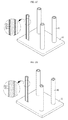
- FIG. 2A is a mimetic diagram schematically illustrating a step of depositing metal nanowire.
- FIG. 2B is a mimetic diagram schematically illustrating a step of forming a metal oxide nanowire layer.
- FIG. 2C is a mimetic diagram schematically illustrating a step of coating a conductive layer.
- FIG. 2D is a mimetic diagram schematically illustrating a step of forming a gap between the metal nanowire and the conductive layer.
- the electrode according to an embodiment of the present disclosure comprises an electrode current collector, a metal nanowire formed on a surface of the electrode current collector, and a conductive layer surrounding the outside of the metal nanowire, and a gap may be formed between the metal nanowire and the conductive layer, so that the metal nanowire and the conductive layer are spaced apart from each other without direct contact between them.
- the material that may be applied to the electrode current collector is made of at least one selected from a group consisting of, for example, without limitation, copper; stainless steel; aluminum; nickel; titanium; sintered carbon; stainless steel surface-treated with carbon, nickel, titan or silver; and aluminum-cadmium alloy.
- the metal nanowire is formed on the surface of the electrode current collector, more particularly, a long-axis direction of the metal nanowire is formed to protrude without being attached to the surface of the metal nanowire, and may be formed in an upper direction or a lower direction of the surface of the electrode current collector, and there is an advantage of facilitated movement of electrons in a charging and discharging process.
- the long-axis direction of the metal nanowire and the surface of the electrode current collector may form an angle of 40 to 140°, preferably, 80 to 100°, and more preferably, vertical.
- the metal that may be applied to the metal nanowire of the present disclosure may be at least one selected from a group consisting of silicon, tin, aluminum and germanium, and preferably, germanium, and since germanium has an advantage that its theoretical capacity is about 1600 mAh/g, which is a high capacity that may be up to 4 times or more than that of a carbon-based material, there is an advantage of being applicable to a high capacity apparatus.
- the conductive layer surrounds the outside of the metal nanowire, and more particularly, being spaced apart from the metal nanowire by a certain distance without directly contacting the metal nanowire, it surrounds the outside of the metal nanowire such that it includes a gap therebetween. This generates free space compared to when the metal nanowire and the conductive layer contact each other, which provides an advantage where it may act as a buffer layer that alleviates volume expansion that may occur in a charging and discharging process.
- any material that is capable of serving as a conductive material may be applied, without limitation, to the conductive layer of the electrode according to an embodiment of the present disclosure, a preferable example being a graphene layer, and by comprising the graphene layer having high output characteristics, it is possible to improve the problem of deteriorating output due to deteriorating diffusion as in a germanium nanowire.
- a secondary battery comprising the aforementioned electrode.
- the electrode may be used as an anode, and the battery may further comprise a separator and a cathode.
- the cathode may made of any material being used as a cathode in the related art, without limitation.
- the cathode may be one that a cathode active material may be coated on a surface of a cathode current collector.
- cathode current collector examples include those made of stainless steel; aluminum; nickel; titanium; sintered carbon; stainless steel surface-treated with carbon, nickel, titan or silver; or aluminum-cadmium alloy and the like.
- the separator may be made of any material used in the related art, without limitation, if it is interposed between an anode and a cathode to short-circuit.
- the separator comprises a porous polymer substrate and a porous coating layer coated on at least one surface of the porous polymer substrate.
- Non-limiting examples of the porous polymer substrate include a porous polymer film made of polyolefin such as polyethylene and polypropylene, and such a polyolefin porous polymer film substrate exhibits a shutdown function at a temperature of, for example, 80 to 130° C.
- the polyolefin porous polymer film may be formed from a polymer obtained by mixing polyolefin polymer such as polyethylene such as high density polyethylene, linear low density polyethylene, low density polyethylene and ultra-high molecular polyethylene, polypropylene, polybutylene, and polypentene and the like, solely or in combination of two or more thereof.
- polyethylene such as high density polyethylene, linear low density polyethylene, low density polyethylene and ultra-high molecular polyethylene, polypropylene, polybutylene, and polypentene and the like, solely or in combination of two or more thereof.
- porous polymer film substrate may be molded in the form of a film by using various polymers such as polyester and the like, besides polyolefin. Further, the porous polymer film substrate may be formed in a structure where two or more film layers are laminated, and each of the film layers may be formed as polymer by mixing the polymer such as the aforementioned polyolefin, polyester and the like, solely or in combination of two or more thereof.
- porous polymer film substrate and porous non-woven substrate may be formed as polymer by mixing polyethyleneterephthalate, polybutyleneterephthalate, polyester, polyacetal, polyamide, polycarbonate, polyimide, polyetheretherketone, polyethersulfone, polyphenyleneoxide, polyphenylenesulfide, polyethylenenaphthalene and the like, solely or in combination thereof, besides the aforementioned polyolefin.
- a thickness of the porous substrate is not particularly limited, but is preferably, 5 to 50 ⁇ m, and a size of a pore existing in the porous substrate is not limited as long as it is smaller than polymer binder fiber of an electrode adhesion layer, but is preferably, 0.001 to 50 ⁇ m, and its air porosity is preferably 1 to 99%.
- a porous coating layer may be further included on at least one surface of the porous polymer substrate aforementioned as the separator that may be applied to the present application, and the porous coating layer may include an inorganic particle and binder polymer.
- the inorganic particles are bound to each other by the binder polymer in the state that the particles are substantially present in contact with each other to form a closest packed structure, and an interstitial volume is generated from the contact of the inorganic particles with each other and turns into empty space, thereby forming pores.
- the binder polymer allows the adhesion of inorganic particles so that the inorganic particles can be bound with each other, for example, the binder polymer connects and immobilizes the inorganic particles therebetween.
- the pore of the porous coating layer is formed as the interstitial volume between the inorganic particles turned into an empty space, which is a space limited by the inorganic particles substantially surface-contacting in a closed packed or densely packed structure by the inorganic particles. Through such a pore of the porous coating layer, a path through which a lithium ion that is essential for operating the battery moves may be provided.
- the inorganic particle is not particularly limited as long as it is electrochemically stable. That is, the inorganic particle that may be used in the present disclosure is not particularly limited as long as it is one that does not generate an oxidization and/or a reduction reaction in an operating voltage range (for example, 0 to 5 V with reference to Li/Li + ) of an electrochemical device being applied. Especially, in the case of using an inorganic particle having a high dielectricity, as the inorganic particle, it may contribute to an increase of electrolyte salt within liquid electrolyte, for example, increase of a degree of dissociation of lithium salt, thereby enhancing the ion conductivity of the electrolyte.
- the inorganic particle may comprise an inorganic particle of a high dielectricity of which the dielectric constant is 5 or above, and preferably, 10 or above, or an inorganic particle having an ability of transmitting a lithium ion, or a mixture thereof.
- Non-limiting examples of the inorganic particle having a dielectric constant of 5 or above comprise any one or a mixture of two or more selected from a group consisting of BaTiO 3 , Pb(Zr x Ti 1-x )O 3 (PZT, 0 ⁇ x ⁇ 1), Pb 1-x La x Zr 1-y Ti y O 3 (PLZT, 0 ⁇ x ⁇ 1, 0 ⁇ y ⁇ 1), (1 ⁇ x)Pb(Mg 1/3 Nb 2/3 )O 3 ⁇ xPbTiO 3 (PMN-PT, 0 ⁇ x ⁇ 1), hafnia(HfO 2 ), SrTiO 3 , SnO 2 , CeO 2 , MgO, NiO, CaO, ZnO, ZrO 2 , SiO 2 , Y 2 O 3 , Al 2 O 3 , SiC and TiO 2 , and such inorganic particles not only exhibit high dielectricity characteristics of a dielectric constant of 100 or above, but also have piezo
- the inorganic particles having the ability to transport lithium ions refer to inorganic particles containing lithium atom which are capable of moving lithium ions without storing the lithium.
- Non-limiting examples of the inorganic particles having the ability to transport lithium ions include lithium phosphate (Li 3 PO 4 ), lithium titanium phosphate (Li x Ti y (PO 4 ) 3 , 0 ⁇ x ⁇ 2, 0 ⁇ y ⁇ 3), lithium aluminum titanium phosphate (Li x Al y Ti z (PO 4 ) 3 , 0 ⁇ x ⁇ 2, 0 ⁇ y ⁇ 1, 0 ⁇ z ⁇ 3), (LiAlTiP) x O y type glass (0 ⁇ x ⁇ 4, 0 ⁇ y ⁇ 13), lithium lanthanum titanate (Li x La y TiO 3 , 0 ⁇ x ⁇ 2, 0 ⁇ y ⁇ 3), lithium germanium thiophosphate (Li x Ge y P z S w , 0 ⁇ x ⁇ 4, 0 ⁇ y ⁇ 1, 0 ⁇ z ⁇ 1, 0
- the size of the inorganic particle of the porous coating layer is not limited, but for the sake of forming a coating layer with a uniform thickness and an appropriate porosity, the preferable size is within a range of 0.001 to 10 ⁇ m, if possible.
- the polymer binder for forming the porous coating layer may be used without limitation as long as it is a binder that may be used to form a porous coating layer together with an inorganic particle, but preferably, it may be an organic binder polymer or an aqueous binder polymer.
- FIG. 1 is a flowchart illustrating a method for manufacturing an electrode according to an embodiment of the present disclosure.
- the method for manufacturing an electrode of the present disclosure comprises a step of depositing metal nanowire (S 10 ), a step of forming metal oxide nanowire (S 20 ), a step of coating a conductive layer (S 30 ) and a step of forming a gap (S 40 ).
- the metal nanowire is deposited such that it faces towards an upper direction or a lower direction of a surface of an electrode current collector.
- FIG. 2A is a perspective view illustrating a state where the metal nanowire is deposited on the surface of the electrode current collector, and referring to FIG. 2A , the metal nanowire 20 is deposited in the upper direction on the surface of the electrode current collector 10 in accordance with an embodiment of the present disclosure.
- the electrode current collector used in the method for manufacturing an electrode of the present disclosure may be at least one selected from a group consisting of copper; stainless steel; aluminum; nickel; titanium; sintered carbon; stainless steel surface-treated with carbon, nickel, titanium or silver; and aluminum-cadmium alloy, and preferably, stainless steel.
- the deposition of the metal nanowire on the surface of the electrode current collector in the present disclosure may be carried out by any method for depositing metal on a metal surface of the related art, without limitation.
- a chemical vapor deposition may be used.
- metal oxide nanowire (S 20 ) a portion of the surface of the deposited metal nanowire is oxidized to form a metal oxide nanowire layer.
- FIG. 2B is a perspective view illustrating a state where the metal oxide metal nanowire is formed according to an embodiment of the present disclosure, and referring to FIG. 2B , a metal oxide nanowire layer 30 is formed on a partial portion of the metal nanowire 20 .
- the metal nanowire layer being oxidized occupies a portion of the surface in a predetermined thickness and turns into a gap later on. That is, it does not mean that the metal nanowire layer is entirely oxidized.
- the oxidizing method may be varied depending on the metal of the metal nanowire being applied, and in the case of a metal that is easily oxidized in the atmosphere, the metal oxide nanowire layer may be formed by bringing the metal into being left in the atmosphere without adding an additional oxidizer.
- the metal oxide nanowire layer may be formed by conducting the oxidization reaction under an oxygen atmosphere at a high temperature.
- the conductive layer is coated on a surface of the metal oxide nanowire layer.
- FIG. 2C is a perspective view illustrating a state where the conductive layer is coated on the surface of the metal oxide nanowire layer, and referring to FIG. 2C , by the step of coating a conductive layer (S 30 ), the conductive layer 40 is coated on the surface of the metal oxide nanowire layer 30 .
- the method for coating a conductive material on the surface of the metal layer may be applied without limitation.
- the metal oxide itself acts as a catalyst for synthesizing the conductive layer
- a heterogeneous metal catalyst such as iron, nickel and the like generally used as the catalyst for synthesizing a conductive layer, and thus there is an advantage of minimizing the effect of impurities.
- nitrate (HNO 3 ) and the like is generally used to dissolve the heterogeneous catalyst, but the metal oxide of the present disclosure that performs the role of a catalyst may be dissolved in water and easily removed, and thus there is an advantage of reducing chemical damages to the conductive layer.
- the metal oxide nanowire manufactured at the step of forming a metal oxide nanowire (S 20 ) is removed and the place of the removed metal oxide nanowire turns into a gap, thereby forming the metal nanowire and the conductive layer to be spaced apart from each other.
- FIG. 2D is a perspective view illustrating a state where the gap is formed between the metal nanowire layer 20 and the conductive layer 40 , and referring to FIG. 2D , it can be seen that as the existing metal oxide nanowire layer 30 is removed and the place generated by the removal turns into the gap.
- the metal oxide nanowire layer 30 may be manufactured by action that it is easily dissolved in water.
- an electrode manufactured by the aforementioned manufacturing method and a secondary battery comprising the same.
Landscapes
- Chemical & Material Sciences (AREA)
- Chemical Kinetics & Catalysis (AREA)
- Electrochemistry (AREA)
- General Chemical & Material Sciences (AREA)
- Engineering & Computer Science (AREA)
- Materials Engineering (AREA)
- Manufacturing & Machinery (AREA)
- Composite Materials (AREA)
- Cell Electrode Carriers And Collectors (AREA)
- Battery Electrode And Active Subsutance (AREA)
Applications Claiming Priority (3)
| Application Number | Priority Date | Filing Date | Title |
|---|---|---|---|
| KR1020150003623A KR101773103B1 (ko) | 2015-01-09 | 2015-01-09 | 전극, 이의 제조방법, 이에 의해 제조된 전극 및 이를 포함하는 이차전지 |
| KR10-2015-0003623 | 2015-01-09 | ||
| PCT/KR2016/000246 WO2016111605A1 (fr) | 2015-01-09 | 2016-01-11 | Électrode, son procédé de fabrication, électrode fabriquée par le procédé, et batterie rechargeable la comprenant |
Publications (2)
| Publication Number | Publication Date |
|---|---|
| US20170222216A1 US20170222216A1 (en) | 2017-08-03 |
| US10388946B2 true US10388946B2 (en) | 2019-08-20 |
Family
ID=56356215
Family Applications (1)
| Application Number | Title | Priority Date | Filing Date |
|---|---|---|---|
| US15/515,401 Active 2036-10-18 US10388946B2 (en) | 2015-01-09 | 2016-01-11 | Electrode, method for manufacturing the same, electrode manufactured by the method, and secondary battery comprising the same |
Country Status (6)
| Country | Link |
|---|---|
| US (1) | US10388946B2 (fr) |
| EP (1) | EP3193394B1 (fr) |
| JP (1) | JP6574247B2 (fr) |
| KR (1) | KR101773103B1 (fr) |
| CN (1) | CN107078289B (fr) |
| WO (1) | WO2016111605A1 (fr) |
Families Citing this family (6)
| Publication number | Priority date | Publication date | Assignee | Title |
|---|---|---|---|---|
| KR102609647B1 (ko) | 2018-02-07 | 2023-12-05 | 소니 세미컨덕터 솔루션즈 가부시키가이샤 | 고체 촬상 소자 및 촬상 장치 |
| CN110556535A (zh) * | 2019-09-17 | 2019-12-10 | 上海理工大学 | 一种柔性三维金属锂负极材料的制备方法 |
| KR102918426B1 (ko) | 2021-10-26 | 2026-01-28 | 삼성전기주식회사 | 커패시터 부품 및 커패시터 부품 제조 방법 |
| CN117276476B (zh) | 2022-06-14 | 2025-02-25 | 广东小天才科技有限公司 | 中间结构及制备方法、锂二次电池电极及制备方法 |
| US12525397B2 (en) | 2022-12-29 | 2026-01-13 | Samsung Electro-Mechanics Co., Ltd. | Capacitor component and manufacturing method of capacitor component |
| KR20240106886A (ko) | 2022-12-29 | 2024-07-08 | 삼성전기주식회사 | 커패시터 부품 및 커패시터 부품 제조 방법 |
Citations (12)
| Publication number | Priority date | Publication date | Assignee | Title |
|---|---|---|---|---|
| US20110111227A1 (en) | 2009-11-09 | 2011-05-12 | Mark Crocker | Method for production of germanium nanowires encapsulated within multi-walled carbon nanotubes |
| US20110195311A1 (en) | 2010-02-08 | 2011-08-11 | Beom-Kwon Kim | Negative electrode for rechargeable lithium battery, method for manufacturing thereof, and rechargeable lithium battery comprising the same |
| US20120094192A1 (en) * | 2010-10-14 | 2012-04-19 | Ut-Battelle, Llc | Composite nanowire compositions and methods of synthesis |
| KR20120089512A (ko) | 2010-12-13 | 2012-08-13 | 한양대학교 산학협력단 | 리튬 이차 전지용 음극 활물질, 그 제조방법 및 이를 포함하는 리튬 이차 전지 |
| US8440350B1 (en) * | 2011-11-10 | 2013-05-14 | GM Global Technology Operations LLC | Lithium-ion battery electrodes with shape-memory-alloy current collecting substrates |
| US8574744B1 (en) * | 2005-05-13 | 2013-11-05 | The University Of Tulsa | Nanoscale three-dimensional battery architecture |
| KR20130126796A (ko) | 2012-04-19 | 2013-11-21 | 삼성전자주식회사 | 전기화학 커패시터용 전극 및 이를 포함하는 전기화학 커패시터 |
| US20140302385A1 (en) | 2013-04-05 | 2014-10-09 | Postech Academy-Industry Foundation | Electrode for lithium secondary battery, lithium secondary battery using the same, and method of fabricating the same |
| KR20140130578A (ko) | 2013-05-01 | 2014-11-11 | 한국과학기술원 | 나노섬유와 그래핀의 복합체를 이용한 리튬-이온 이차전지용 음극활물질 및 그 제조 방법 |
| US20160032475A1 (en) * | 2014-07-31 | 2016-02-04 | Imec Vzw | Method for Nanowire Cluster Formation |
| US20160118643A1 (en) * | 2009-08-01 | 2016-04-28 | Samsung Electronics Co., Ltd. | Method for manufacturing an electrode for lithium ion batteries |
| US20170062834A1 (en) * | 2014-02-21 | 2017-03-02 | Nederlandse Organisatie Voor Toegepast-Natuurwetenschappelijkonderzoek Tno | A device and method of manufacturing high-aspect ratio structures |
Family Cites Families (8)
| Publication number | Priority date | Publication date | Assignee | Title |
|---|---|---|---|---|
| EP2849265B1 (fr) * | 2008-02-22 | 2021-05-12 | Colorado State University Research Foundation | Batterie au lithium-ion |
| US20100285358A1 (en) * | 2009-05-07 | 2010-11-11 | Amprius, Inc. | Electrode Including Nanostructures for Rechargeable Cells |
| CN105206794B (zh) * | 2010-03-03 | 2018-02-23 | 安普瑞斯股份有限公司 | 用于沉积活性材料的模板电极结构 |
| CN102244254A (zh) * | 2011-06-17 | 2011-11-16 | 天津大学 | 一种中空纳米线-聚合物膜核壳结构复合材料及其制备方法 |
| EP2727175A4 (fr) * | 2011-07-01 | 2015-07-01 | Amprius Inc | Structures d'électrodes à matrice présentant des caractéristiques d'adhérence améliorées |
| GB2502625B (en) * | 2012-06-06 | 2015-07-29 | Nexeon Ltd | Method of forming silicon |
| KR101557559B1 (ko) * | 2012-11-30 | 2015-10-07 | 주식회사 엘지화학 | 리튬 이차 전지용 음극재, 이의 제조 방법 및 이를 포함하는 리튬 이차 전지 |
| CN103943836B (zh) * | 2014-04-01 | 2016-09-21 | 太原理工大学 | 锂离子电池负极材料中空锗纳米管阵列电极及其制备方法 |
-
2015
- 2015-01-09 KR KR1020150003623A patent/KR101773103B1/ko active Active
-
2016
- 2016-01-11 JP JP2017517278A patent/JP6574247B2/ja active Active
- 2016-01-11 US US15/515,401 patent/US10388946B2/en active Active
- 2016-01-11 EP EP16735226.9A patent/EP3193394B1/fr active Active
- 2016-01-11 CN CN201680003324.8A patent/CN107078289B/zh active Active
- 2016-01-11 WO PCT/KR2016/000246 patent/WO2016111605A1/fr not_active Ceased
Patent Citations (14)
| Publication number | Priority date | Publication date | Assignee | Title |
|---|---|---|---|---|
| US8574744B1 (en) * | 2005-05-13 | 2013-11-05 | The University Of Tulsa | Nanoscale three-dimensional battery architecture |
| US20160118643A1 (en) * | 2009-08-01 | 2016-04-28 | Samsung Electronics Co., Ltd. | Method for manufacturing an electrode for lithium ion batteries |
| US20110111227A1 (en) | 2009-11-09 | 2011-05-12 | Mark Crocker | Method for production of germanium nanowires encapsulated within multi-walled carbon nanotubes |
| KR101147201B1 (ko) | 2010-02-08 | 2012-05-25 | 삼성에스디아이 주식회사 | 리튬이차전지의 음극, 이의 제조 방법 및 상기 음극전극을 포함하는 리튬 이차전지 |
| US20110195311A1 (en) | 2010-02-08 | 2011-08-11 | Beom-Kwon Kim | Negative electrode for rechargeable lithium battery, method for manufacturing thereof, and rechargeable lithium battery comprising the same |
| US20120094192A1 (en) * | 2010-10-14 | 2012-04-19 | Ut-Battelle, Llc | Composite nanowire compositions and methods of synthesis |
| KR20120089512A (ko) | 2010-12-13 | 2012-08-13 | 한양대학교 산학협력단 | 리튬 이차 전지용 음극 활물질, 그 제조방법 및 이를 포함하는 리튬 이차 전지 |
| US8440350B1 (en) * | 2011-11-10 | 2013-05-14 | GM Global Technology Operations LLC | Lithium-ion battery electrodes with shape-memory-alloy current collecting substrates |
| KR20130126796A (ko) | 2012-04-19 | 2013-11-21 | 삼성전자주식회사 | 전기화학 커패시터용 전극 및 이를 포함하는 전기화학 커패시터 |
| US20140302385A1 (en) | 2013-04-05 | 2014-10-09 | Postech Academy-Industry Foundation | Electrode for lithium secondary battery, lithium secondary battery using the same, and method of fabricating the same |
| KR20140121096A (ko) | 2013-04-05 | 2014-10-15 | 포항공과대학교 산학협력단 | 리튬 이차전지용 음극, 이를 이용한 리튬 이차전지 및 그 제조방법 |
| KR20140130578A (ko) | 2013-05-01 | 2014-11-11 | 한국과학기술원 | 나노섬유와 그래핀의 복합체를 이용한 리튬-이온 이차전지용 음극활물질 및 그 제조 방법 |
| US20170062834A1 (en) * | 2014-02-21 | 2017-03-02 | Nederlandse Organisatie Voor Toegepast-Natuurwetenschappelijkonderzoek Tno | A device and method of manufacturing high-aspect ratio structures |
| US20160032475A1 (en) * | 2014-07-31 | 2016-02-04 | Imec Vzw | Method for Nanowire Cluster Formation |
Non-Patent Citations (6)
| Title |
|---|
| Chan et al., "High Capacity Li Ion Battery Anodes Using Ge Nanowires", Nano Letters, 2008, vol. 8, No. 1, pp. 307-309. |
| Chen, S., et al, "Silicon core-hollow carbon shell nanocomposites with tunable buffer voids for high capacity anodes of lithium-ion batteries," Phys.Chem.Chem.Phys., Jul. 27, 2012, vol. 14, No. 37, pp. 12741-12745. |
| Guan, C. et al, "Highly Stable and Reversible Lithium Storage in SnO2 Nanowires Surface Coated with a Uniform Hollow Shell by Atomic Layer Deposition," Nano Letters, Jul. 24, 2014, vol. 14, No. 8, pp. 4852-4858. |
| International Search Report issued in PCT/KR2016/000246, dated Apr. 21, 2016. |
| Ruffo et al., "Impedance Analysis of Silicon Nanowire Lithium Ion Battery Anodes", J. Phys. Chem. C, vol. 113, No. 26, 2009, pp. 11390-11398. |
| Seng, K.H., et al, "Self-Assembled Germanium/Carbon Nanostructures as High-Power Anode Material for the Lithium-Ion Battery," Angew. Chem. Apr. 26, 2012, vol. 124, No. 23, pp. 5755-5759. |
Also Published As
| Publication number | Publication date |
|---|---|
| WO2016111605A1 (fr) | 2016-07-14 |
| KR101773103B1 (ko) | 2017-08-30 |
| KR20160086195A (ko) | 2016-07-19 |
| JP6574247B2 (ja) | 2019-09-11 |
| CN107078289B (zh) | 2020-06-16 |
| EP3193394B1 (fr) | 2019-07-31 |
| EP3193394A4 (fr) | 2018-03-28 |
| CN107078289A (zh) | 2017-08-18 |
| US20170222216A1 (en) | 2017-08-03 |
| JP2018501605A (ja) | 2018-01-18 |
| EP3193394A1 (fr) | 2017-07-19 |
Similar Documents
| Publication | Publication Date | Title |
|---|---|---|
| US10388946B2 (en) | Electrode, method for manufacturing the same, electrode manufactured by the method, and secondary battery comprising the same | |
| JP5692184B2 (ja) | 全固体リチウムイオン二次電池 | |
| US9590241B2 (en) | Electrode for secondary battery, secondary battery and cable-type secondary battery comprising the same | |
| RU2499333C1 (ru) | Материал положительного электрода для электрического устройства и электрическое устройство, произведенное с его использованием | |
| JP6316207B2 (ja) | 二次電池用電極、それを含む二次電池及びケーブル型二次電池 | |
| KR102722956B1 (ko) | 이차전지용 음극 및 그를 포함하는 이차전지 | |
| KR101667520B1 (ko) | 무기물 코팅층을 포함하는 전극조립체 및 이를 포함하는 이차전지 | |
| EP2983230A1 (fr) | Matériau actif de cathode pour batterie au lithium, batterie au lithium et procédé de production de matériau actif de cathode pour batterie au lithium | |
| EP2854206A1 (fr) | Matériau actif d'anode à haute capacité pour batterie secondaire au lithium, procédé de fabrication associé, et batterie secondaire au lithium comprenant ledit matériau actif d'anode à haute capacité | |
| EP2950370A1 (fr) | Batterie secondaire au lithium-ion | |
| KR20130076810A (ko) | 비수 전해질 전지용 정극체 및 그 제조 방법, 그리고 비수 전해질 전지 | |
| WO2014181885A1 (fr) | Composite d'oxyde de lithium et de manganèse, batterie secondaire et leur procédé de fabrication | |
| KR101874159B1 (ko) | 리튬 이차전지용 전극의 제조방법 및 이로부터 제조된 리튬 이차전지용 전극 | |
| KR102400731B1 (ko) | 리튬 금속 전극을 구비하는 리튬 이차 전지 | |
| CN108780921A (zh) | 聚合物电解质和包括该聚合物电解质的锂二次电池 | |
| US10374203B2 (en) | Heat-diffusible separation film and secondary cell comprising the same | |
| KR20220100537A (ko) | 양극 및 이를 포함하는 리튬 이차전지 | |
| KR101484845B1 (ko) | 리튬 이온 이동로가 구비된 고체 전해질을 포함하는 이차전지, 및 그의 제조방법 | |
| US20250183479A1 (en) | Separator for electrochemical device, and electrochemical device having same | |
| CN114730962A (zh) | 电化学装置及用电设备 | |
| KR101654680B1 (ko) | 이차전지용 전극 및 그를 포함하는 케이블형 이차전지 | |
| KR102691334B1 (ko) | 이차전지용 분리막, 이의 제조방법 및 이차전지 | |
| KR101773656B1 (ko) | 이차 전지용 음극, 이를 포함하는 전극 조립체 및 이차전지 | |
| EP3297085A1 (fr) | Ensemble d'électrode pour une cellule de batterie et cellule de batterie | |
| US20250192363A1 (en) | Separator for secondary battery, method for manufacturing same, and secondary battery |
Legal Events
| Date | Code | Title | Description |
|---|---|---|---|
| AS | Assignment |
Owner name: LG CHEM, LTD., KOREA, REPUBLIC OF Free format text: ASSIGNMENT OF ASSIGNORS INTEREST;ASSIGNORS:WOO, SUN-HWAK;CHOI, YOUNG-GEUN;KIM, HYE-BIN;AND OTHERS;REEL/FRAME:041800/0668 Effective date: 20170104 |
|
| STPP | Information on status: patent application and granting procedure in general |
Free format text: NON FINAL ACTION MAILED |
|
| STPP | Information on status: patent application and granting procedure in general |
Free format text: RESPONSE TO NON-FINAL OFFICE ACTION ENTERED AND FORWARDED TO EXAMINER |
|
| STPP | Information on status: patent application and granting procedure in general |
Free format text: NOTICE OF ALLOWANCE MAILED -- APPLICATION RECEIVED IN OFFICE OF PUBLICATIONS |
|
| STPP | Information on status: patent application and granting procedure in general |
Free format text: PUBLICATIONS -- ISSUE FEE PAYMENT VERIFIED |
|
| STCF | Information on status: patent grant |
Free format text: PATENTED CASE |
|
| AS | Assignment |
Owner name: LG ENERGY SOLUTION, LTD., KOREA, REPUBLIC OF Free format text: ASSIGNMENT OF ASSIGNORS INTEREST;ASSIGNOR:LG CHEM, LTD.;REEL/FRAME:058295/0068 Effective date: 20211027 |
|
| MAFP | Maintenance fee payment |
Free format text: PAYMENT OF MAINTENANCE FEE, 4TH YEAR, LARGE ENTITY (ORIGINAL EVENT CODE: M1551); ENTITY STATUS OF PATENT OWNER: LARGE ENTITY Year of fee payment: 4 |