US10390331B2 - System information provisioning and light weight connection signaling - Google Patents
System information provisioning and light weight connection signaling Download PDFInfo
- Publication number
- US10390331B2 US10390331B2 US15/492,571 US201715492571A US10390331B2 US 10390331 B2 US10390331 B2 US 10390331B2 US 201715492571 A US201715492571 A US 201715492571A US 10390331 B2 US10390331 B2 US 10390331B2
- Authority
- US
- United States
- Prior art keywords
- system information
- cell
- network
- information
- broadcast
- Prior art date
- Legal status (The legal status is an assumption and is not a legal conclusion. Google has not performed a legal analysis and makes no representation as to the accuracy of the status listed.)
- Active
Links
Images




Classifications
-
- H—ELECTRICITY
- H04—ELECTRIC COMMUNICATION TECHNIQUE
- H04W—WIRELESS COMMUNICATION NETWORKS
- H04W48/00—Access restriction; Network selection; Access point selection
- H04W48/08—Access restriction or access information delivery, e.g. discovery data delivery
- H04W48/14—Access restriction or access information delivery, e.g. discovery data delivery using user query or user detection
-
- H—ELECTRICITY
- H04—ELECTRIC COMMUNICATION TECHNIQUE
- H04W—WIRELESS COMMUNICATION NETWORKS
- H04W72/00—Local resource management
- H04W72/04—Wireless resource allocation
-
- H—ELECTRICITY
- H04—ELECTRIC COMMUNICATION TECHNIQUE
- H04W—WIRELESS COMMUNICATION NETWORKS
- H04W16/00—Network planning, e.g. coverage or traffic planning tools; Network deployment, e.g. resource partitioning or cells structures
- H04W16/02—Resource partitioning among network components, e.g. reuse partitioning
-
- H—ELECTRICITY
- H04—ELECTRIC COMMUNICATION TECHNIQUE
- H04W—WIRELESS COMMUNICATION NETWORKS
- H04W36/00—Hand-off or reselection arrangements
-
- H—ELECTRICITY
- H04—ELECTRIC COMMUNICATION TECHNIQUE
- H04W—WIRELESS COMMUNICATION NETWORKS
- H04W4/00—Services specially adapted for wireless communication networks; Facilities therefor
- H04W4/06—Selective distribution of broadcast services, e.g. multimedia broadcast multicast service [MBMS]; Services to user groups; One-way selective calling services
-
- H—ELECTRICITY
- H04—ELECTRIC COMMUNICATION TECHNIQUE
- H04W—WIRELESS COMMUNICATION NETWORKS
- H04W48/00—Access restriction; Network selection; Access point selection
-
- H—ELECTRICITY
- H04—ELECTRIC COMMUNICATION TECHNIQUE
- H04W—WIRELESS COMMUNICATION NETWORKS
- H04W48/00—Access restriction; Network selection; Access point selection
- H04W48/08—Access restriction or access information delivery, e.g. discovery data delivery
- H04W48/10—Access restriction or access information delivery, e.g. discovery data delivery using broadcasted information
-
- H—ELECTRICITY
- H04—ELECTRIC COMMUNICATION TECHNIQUE
- H04W—WIRELESS COMMUNICATION NETWORKS
- H04W76/00—Connection management
- H04W76/10—Connection setup
-
- H—ELECTRICITY
- H04—ELECTRIC COMMUNICATION TECHNIQUE
- H04W—WIRELESS COMMUNICATION NETWORKS
- H04W76/00—Connection management
- H04W76/10—Connection setup
- H04W76/18—Management of setup rejection or failure
Definitions
- LTE Long-Term Evolution, sometimes called 4G LTE
- 4G LTE Long-Term Evolution, sometimes called 4G LTE
- GSM Global System for Mobile communications
- EDGE Enhanced Data rates for GSM Evolution
- UMTS Universal Mobile Telecommunications System
- HSPA High Speed Packet Access
- the Radio Resource Control (RRC) protocol is the Radio Resource Control protocol used in UMTS and LTE on the Air interface. It handles the control plane signaling of Layer 3 between the User Equipment (UE) and the Radio Access Network (Universal Terrestrial Radio Access Network (UTRAN) or Evolved Universal Terrestrial Radio Access Network (E-UTRAN)) as well as for the radio interface between a Relay Node and the E-UTRAN.
- This protocol is specified by the 3rd Generation Partnership Project (3GPP) in TS 25.331 for UMTS and in TS 36.331 for LTE.
- RRC messages are transported via the PDCP-Protocol.
- the major functions of the RRC protocol include connection establishment and release functions, broadcast of system information, radio bearer establishment, reconfiguration and release, RRC connection mobility procedures, paging notification and release and outer loop power control.
- connection establishment and release functions include connection establishment and release functions, broadcast of system information, radio bearer establishment, reconfiguration and release, RRC connection mobility procedures, paging notification and release and outer loop power control.
- the RRC configures the user and control planes according to the network status and allows for Radio Resource Management strategies to be implemented.
- FIG. 1 shows Radio Resource Control (RRC) Protocol States for Long Term Evolution (LTE).
- RRC Radio Resource Control
- LTE Long Term Evolution
- RRC_CONNECTED there is an RRC context.
- the cell to which the User Equipment (UE) belongs is known and an identity of the UE, the Cell Radio-Network Temporary Identifier (C-RNTI), used for signaling purposes between the UE and the network, has been configured.
- C-RNTI Cell Radio-Network Temporary Identifier
- RRC_CONNECTED is intended for data transfer to/from the UE.
- FIG. 2 provides an overview of the RRC states in Evolved Universal Terrestrial Radio Access (E-UTRA) with the illustration of the mobility support between E-UTRAN, UTRAN and GSM EDGE Radio Access Network (GERAN).
- E-UTRA Evolved Universal Terrestrial Radio Access
- GERAN GSM EDGE Radio Access Network
- Mobility State of UE (36.304): Besides Normal-mobility state, a High-mobility and a Medium-mobility state are applicable if the parameters (TCRmax, NCR_H, NCR_M and TCRmaxHyst) are sent in the system information broadcast of the serving cell. These states can be considered substates as related to mobility in RRC_IDLE state.
- NCR_M This specifies the maximum number of cell reselections to enter Medium-mobility state.
- NCR_H This specifies the maximum number of cell reselections to enter High-mobility state.
- TCRmax This specifies the duration for evaluating allowed amount of cell reselection(s).
- TCRmaxHyst This specifies the additional time period before the UE can enter Normal-mobility state.
- the UE shall not count consecutive reselections between same two cells into mobility state detection criteria if same cell is reselected just after one other reselection.
- the UE shall:
- Non-access Stratum NAS Protocol for LTE Details of the Non-access Stratum NAS Protocol for LTE are described in 3GPP TS 23.401 and 3GPP TS 24.301. A summary is provided below.
- the non-access stratum forms the highest stratum of the control plane between UE and MME at the radio interface over the reference point Uu.
- Main functions of the protocols that are part of the NAS are:
- the NAS consists of two separate protocols that are carried on direct signaling transport between the UE and for e.g. the Mobile Management Entity (MME) in the Core Network (CN).
- MME Mobile Management Entity
- CN Core Network
- the content of the NAS layer protocols is not visible to the Radio Access Network (RAN) nodes (e.g. eNodeB), and the RAN nodes are not involved in these transactions by any other means, besides transporting the messages, and providing some additional transport layer indications along with the messages in some cases.
- the NAS layer protocols include EPS Mobility Management (EMM), and EPS Session Management (ESM).
- EMM EPS Mobility Management
- TAU Tracking Area Updating
- Paging Packet Control Protocol
- Authentication and protecting the UE identity i.e. allocating the temporary identity Globally Unique Temporary UE Identity GUTI to the UE are also part of the EMM layer, as well as the control of NAS layer security functions, encryption and integrity protection.
- Example of EMM procedures include attach procedure (for registration), detach procedure, service request procedure, tracking area update procedure, connection suspend, connection resume procedure and UE reachability procedure.
- NAS security is an additional function of the NAS providing services to the NAS protocols, e.g. integrity protection and ciphering of NAS signaling messages.
- ESM EPS Session Management
- the overall Evolved Packet System Control Plane Protocol stack is depicted in FIG. 3 .
- RRC_IDLE there is no RRC context in the Radio Access Network (RAN) and the UE does not belong to a specific cell. No data transfer may take place in RRC_IDLE.
- a UE in RRC_IDLE monitors a Paging channel to detect incoming calls and changes to the system information. Discontinuous Reception (DRX) is used in to conserve UE power.
- DRX Discontinuous Reception
- the System Information is the information broadcast by the Evolved Universal Terrestrial Radio Access Network (E-UTRAN) that needs to be acquired by the User Equipment (UE) to be able to access and operate within the network.
- E-UTRAN Evolved Universal Terrestrial Radio Access Network
- UE User Equipment
- System information is divided into the MasterInformationBlock (MIB) and a number of SystemInformationBlocks (SIBs).
- MIB MasterInformationBlock
- SIBs SystemInformationBlocks
- BCH Broadcast Channel
- SIBs other than SystemInformationBlockType1 are carried in SystemInformation (SI) messages and mapping of SIBs to SI messages is flexibly configurable by schedulingInfoList included in SystemInformationBlockType1, with restrictions that: each SIB is contained only in a single SI message, and at most once in that message; only SIBs having the same scheduling requirement (periodicity) can be mapped to the same SI message; SystemInformationBlockType2 is always mapped to the SI message that corresponds to the first entry in the list of SI messages in schedulingInfoList. There may be multiple SI messages transmitted with the same periodicity.
- SIBlockType1 and all SI messages are transmitted on DL-SCH
- SIB2 Detailed descriptions of the MIB and SIB1 are available in section 6.2.2 of 3GPP TS 36.331. Detailed descriptions of the remaining SIBs (SIB2-SIB20) are available in section 6.3.1 of 3GPP TS 36.331.
- the MIB and SIB1 use a fixed schedule with a periodicity of 40 ms and 80 ms respectively.
- the remaining SIBs use a flexible schedule that can be network dependent.
- the following excerpt from section 5.2.1.2 of 3GPP TS 36.331 describes the scheduling in more detail:
- the MIB uses a fixed schedule with a periodicity of 40 ms and repetitions made within 40 ms.
- the SystemInformationBlockType1 uses a fixed schedule with a periodicity of 80 ms and repetitions made within 80 ms.
- the SI messages are transmitted within periodically occurring time domain windows (referred to as SI-windows) using dynamic scheduling.
- SI-windows time domain windows
- Each SI message is associated with a SI-window and the SI-windows of different SI messages do not overlap. That is, within one SI-window only the corresponding SI is transmitted.
- the length of the SI-window is common for all SI messages, and is configurable.
- TDD Time Division Duplex
- the UE acquires the detailed time-domain scheduling (and other information, e.g. frequency-domain scheduling, used transport format) from decoding SI-RNTI on Physical Downlink Control Channel (PDCCH) (see TS 36.321).
- PDCH Physical Downlink Control Channel
- a single SI-RNTI is used to address SystemInformationBlockType1 as well as all SI messages.
- SystemInformationBlockType1 configures the SI-window length and the transmission periodicity for the SI messages.”
- System information validity and notification of changes is described in detail in section 5.2.1.3 of 3GPP TS 36.331.
- Change of system information other than for Earthquake and Tsunami Warning System (ETWS), Commercial Mobile Alert System (CMAS) and Extended Access Barring (EAB) parameters, occurs at specific radio frames.
- EWS Earthquake and Tsunami Warning System
- CMAS Commercial Mobile Alert System
- EAB Extended Access Barring
- SFN System Frame Number
- blocks 402 are original SI transmitted during modification period (n)
- blocks 404 are updated SI transmitted during modification period (n+1)
- blocks 406 are SI that are not updated at the modification period boundary.
- the Paging message is used to inform UEs in RRC_IDLE and UEs in RRC_CONNECTED about a system information change. If the UE receives a Paging message including the systemInfoModification, it knows that the system information will change at the next modification period boundary.
- SystemInformationBlockType1 includes a value tag, systemInfoValueTag, that indicates if a change has occurred in the SI messages.
- UEs may use systemInfoValueTag, e.g. upon return from out of coverage, to verify if the previously stored SI messages are still valid. Additionally, the UE considers stored system information to be invalid after 3 hours from the moment it was successfully confirmed as valid, unless specified otherwise.
- FIG. 5 is a diagram that illustrates a system information acquisition procedure from 3GPP TS 36.331.
- a UE 502 communicates with U-TRAN 504 for system information acquisition.
- the UE 502 applies the system information acquisition procedure described in section 5.2.2 of 3GPP TS 36.331 to acquire the Access Stratum (AS) and Non-access Stratum (NAS) related system information that is broadcasted by the E-UTRAN 504 .
- the procedure applies to UEs in RRC_IDLE and UEs in RRC_CONNECTED.
- the UE 502 applies the system information acquisition procedure for the following, for example:
- Paging message can be used for system information change notification, when including systemInfoModification-eDRX, for a UE 502 configured with eDRX cycle longer than the system information modification period.
- a bandwidth reduced low complexity (BL) UE can operate in any LTE system bandwidth but with a limited channel bandwidth of 6 PRBs (corresponding to the maximum channel bandwidth available in a 1.4 MHz LTE system) in downlink and uplink.
- a BL UE may access a cell only if the MIB of the cell indicates that access of BL UEs is supported. If not, the UE considers the cell as barred.
- a BL UE receives a separate occurrence of system information blocks (sent using different time/frequency resources).
- a BL UE has a transport block size (TBS) limited to 1000 bit for broadcast and unicast.
- TBS transport block size
- the BL UE determines the scheduling information for SIB1 specific for BL UEs based on information in MIB. Scheduling information for other SIBs is given in SIB1 specific for BL UEs.
- the BCCH modification period for BL UEs is a multiple of the BCCH modification period provided in SIB2.
- the SIB transmission occasions within an SI-window are provided in the SIB1 specific for BL UEs.
- a BL UE can acquire SI messages across SI windows. The maximum number of SI messages that can be acquired across SI windows is 4.
- a BL UE is not required to detect SIB change when in RRC_CONNECTED.
- UE in enhanced coverage is a UE that requires the use of enhanced coverage functionality to access the cell.
- a UE may access a cell using enhanced coverage functionality only if the MIB of the cell indicates that access of UEs in enhanced coverage is supported.
- System information procedures for UEs in enhanced coverage are identical to the system information procedures for bandwidth reduced low complexity UEs.
- a UE capable of enhanced coverage acquires, if needed, and uses legacy system information when in normal coverage if it is not a BL UE.
- a UE capable of enhanced coverage acquires, if needed, and uses system information specific for UEs in enhanced coverage.
- a UE in enhanced coverage is not required to detect SIB change when in RRC_CONNECTED.
- FIG. 6 is high level flow chart illustrating the cell selection and reselection processing performed by the UE 502 in RRC_IDLE.
- the procedure can be entered whenever a new PLMN is selected or if a suitable cell can't be found upon leaving RRC_CONNECTED.
- the UE 502 after a cell is selected, in step 602 , the UE 502 camps on the cell in step 604 and performs the tasks defined in sections 5.2.6 or 5.2.9 of 3GPP TS 36.304, depending on whether the UE 502 has camped on a suitable cell or an acceptable cell, respectively. When camped on a cell, the UE 502 regularly searches for a better cell according to the cell reselection criteria, as defined in section 5.2.3.2 of 3GPP TS 36.304.
- the Cell Reselection Evaluation process is performed according to internal UE 502 triggers or when information on the BCCH used for the cell reselection evaluation procedure has been modified.
- a UE 502 in RRC_IDLE is required to apply the System Information Acquisition procedure as defined in section 5.2.3 of 3GPP TS 36.331 to obtain the following system information for the new serving cell, for example:
- System Information for the new serving cell that is acquired during the Cell Reselection Evaluation Process might not have to be re-acquired following the cell reselection, for example if the information has not changed.
- IMT for 2020 and beyond [Recommendation ITU-R M.2083: IMT Vision—“Framework and overall objectives of the future development of IMT for 2020 and beyond” (September 2015)] is envisaged to expand and support diverse families of usage scenarios and applications that will continue beyond the current IMT. Furthermore, a broad variety of capabilities would be tightly coupled with these intended different usage scenarios and applications for IMT for 2020 and beyond.
- the families of usage scenarios for IMT for 2020 and beyond include, for example:
- this deployment scenario focuses on small coverage per site/TRP (Transmission and Reception Point) and high user throughput or user density in buildings.
- TRP Transmission and Reception Point
- the key characteristics of this deployment scenario are high capacity, high user density and consistent user experience indoor.
- Dense Urban the dense urban microcellular deployment scenario focuses on macro TRPs with or without micro TRPs and high user densities and traffic loads in city centers and dense urban areas. The key characteristics of this deployment scenario are high traffic loads, outdoor and outdoor-to-indoor coverage.
- Urban Macro the urban macro deployment scenario focuses on large cells and continuous coverage. The key characteristics of this scenario are continuous and ubiquitous coverage in urban areas.
- Highway Scenario The highway deployment scenario focuses on scenario of vehicles placed in highways with high speeds.
- the main KPIs evaluated under this scenario would be reliability/availability under high speeds/mobility (and thus frequent handover operations).
- the urban macro deployment scenario focuses on scenario of highly densely deployed vehicles placed in urban area. It could cover a scenario where freeways lead through an urban grid.
- the main KPI evaluated under this scenario are reliability/availability/latency in high network load and high UE density scenarios.
- Examples of mMTC applications include Light Weight Devices, video Surveillance with variable data size and warehouse applications.
- Light Weight Device A very simple device, e.g., with no IMS client (5.1.2.1 of 3GPP TR 22.861), the device could be, for example, a smart electric meter. It records electricity usage, provides up to the minute usage reports that allow the customer to take advantage of time of day rating, and provides a larger, complete report to the electric company once a month. The electric company deploys a large number of these smart meters within an apartment building, one for each apartment.
- the application here is a video Surveillance with variable data size (5.1.2.2 of 3GPP TR 22.861).
- a video recorder is installed and activated at a street corner.
- the video recorder includes a camera, some on-board processing capability, as well as the ability to send information to the traffic police.
- the camera records continuous video, storing the content for some period of time.
- the device periodically sends a status update to the traffic police indicating that traffic is moving smoothly
- the device When an accident occurs at the intersection, the device begins sending high quality video to the traffic police of the accident and ensuing traffic congestion.
- the network will need the flexibility to provide efficient service to the device at all times, whether a small or large amount of data is sent in a given transmission.
- An efficient system could minimize any negative impact to battery life for the device and minimize use of signaling resources.
- the same device will need to establish a connection when it needs to transmit a large amount of data (e.g., video)
- Example of UR/LL Applications include Industrial Process Control, and Local UAV Collaboration and Connectivity.
- Process automation requires communications for supervisory and open-loop control applications, process monitoring and tracking operations on field level inside an industrial plant.
- a large number of sensors ⁇ 10,000 that are distributed over the plant forward measurement data to process controllers on a periodic or event-driven base.
- the use case requires support of a large number of sensor devices (10,000) per plant as well as highly reliable transport (packet loss rate ⁇ 10 ⁇ 5).
- power consumption is critical since most sensor devices are battery-powered with a targeted battery lifetimes of several years while providing measurement updates every few seconds.
- a typical process control application supports downstream and upstream flows between process controllers and sensors/actuators which consist of individual transactions. The process controller resides in the plant network.
- This network interconnects via base stations to the wireless (mesh-) network which hosts the sensor/actuator devices.
- each transaction uses less than 100 bytes.
- upstream and downstream transactions usually occur asynchronously.
- FIG. 7 illustrates an industrial process control example.
- Sensor/activator (S/A) 704 sends a measurement report to process controller 702 .
- Process controller 702 responds with an Acknowledgement (ACK) reply to S/A 704 .
- ACK Acknowledgement
- Process controller 706 sends a measurement request to S/A 708 .
- S/A 708 responds with a measurement response to process controller 706 .
- FIG. 8 is a diagram that illustrates a UAV Communication path.
- UAVs Unmanned Aerial Vehicles
- UAVs can collaborate to act as a mobile sensor and actuator network to execute tasks in uncertain and dynamic environments while being controlled by a single user. Accuracy in sensing tasks is increased when deploying a team of UAVs versus just one as there are multiple vantage points using multiple sensors. Examples of uses for deploying a team of UAVs include: Searching for an intruder or suspect, Continual monitoring of natural disasters, Performing autonomous mapping, collaborative manipulation of an object (e.g. picking up corners of a net.) depicts how communication occurs in UAV local vehicle collaboration and connectivity. Both node to node and UAV to mobile network links are required.
- Example of eMBB Applications include an Office scenario with High Data Rate Applications and an Office scenario with Higher Density of Connections.
- Office scenario with High Data Rate Applications (5.1.2 of 3GPP TR 22.863)—In an office scenario with high data rate needs, users use real-time video meeting and frequently upload and download data from company's servers and they are various in size. The productivity is dependent on the efficiency of the system response time and reliability. Dependent on time of day (e.g. morning, evening, weekday vs. weekend etc.) and the location (e.g. shopping mall, downtown street), user expects multi-media traffic upload and download towards internet as well as D2D communications.
- time of day e.g. morning, evening, weekday vs. weekend etc.
- location e.g. shopping mall, downtown street
- Office scenario with Higher Density of Connections (5.2.1 of 3GPP TR 22.863)—This family covers scenarios with system requirement for the transport of high volume of data traffic per area (traffic density) or transport of data for high number of connections (connection density).
- traffic density traffic density
- connection density transport of data for high number of connections
- One typical scenario enables users to upload and download a very high volume of data from servers, handle high resolution real-time video conferences, etc., while end-users can be under indoor or outdoor and in a densely populated area but with no high mobility needs i.e. up to 60 km/h in urban vehicular.
- a hotspot scenario with high user density depending on time of day (e.g. morning, evening, weekday vs. weekend etc.) and the location (e.g.
- 3GPP TR 38.913 (Study on Scenarios and Requirements for Next Generation Access Technologies) defines scenarios and requirements for next generation (5G) access technologies. The following are excerpts of the Key Performance Indicators (KPI) section of 3GPP TR 38.913 that impose new requirements that are relevant to light signaling connection topic.
- KPI Key Performance Indicators
- Connection density refers to total number of devices fulfilling specific QoS per unit area (per km2).
- QoS definition should take into account the amount of data or access request generated within a time t_gen that can be sent or received within a given time, t_sendrx, with x % probability.
- the target for connection density should be 1 000 000 device/km2 in urban environment.
- 3GPP should develop standards with means of high connection efficiency (measured as supported number of devices per TRP per unit frequency resource) to achieve the desired connection density.
- Control plane latency refers to the time to move from a battery efficient state (e.g., IDLE) to start of continuous data transfer (e.g., ACTIVE).
- the target for control plane latency should be [10 ms].
- UE battery life can be evaluated by the battery life of the UE without recharge.
- UE battery life in extreme coverage shall be based on the activity of mobile originated data transfer consisting of [200 bytes] UL per day followed by [20 bytes] DL from MCL of [tbd] dB, assuming a stored energy capacity of [5 Wh].
- the target for UE battery life should be [10 years].
- the capability is to minimize the RAN energy consumption while providing a much better area traffic capacity.
- Peak data rate is the highest theoretical data rate which is the received data bits assuming error free conditions assignable to a single mobile station, when all assignable radio resources for the corresponding link direction are utilised (i.e., excluding radio resources that are used for physical layer synchronisation, reference signals or pilots, guard bands and guard times).
- the target for peak data rate should be [20 Gbps] for downlink and [10 Gbps] for uplink.
- 5G Requirements Versus the Current State of Art—Current design for LTE (Rel-12) is not efficient in term of transition to RRC-CONNECTED state so a small amount of data can be transmitted or in terms of scalability to support a large number of devices that generate frequent small volume of data.
- the device wakes up and sends data every few minutes.
- UE may need to follow the RACH procedure and subsequently establish signaling radio bearers (through RRC connection establishment procedure) and data radio bearers (through RRC Connection reconfiguration procedure).
- the signaling overhead is substantial when considering only a small amount of data is transmitted in the uplink. This is situation is expected to be worst in light of 5G system diverse use cases and traffic profiles.
- 3GPP TR 23.720 Another key issue identified in 3GPP TR 23.720 is to provide efficient support of tracking devices using small data transmission for Cellular IoT. This key issue aims to provide solution to support highly efficient handling of tracking devices using small data transmissions for ultra-low complexity, power constrained, and low data-rate ‘Internet of Things’ devices, called CIoT devices. It should be noted that excessive signaling will also leads to additional latency and additional power consumption.
- Rel-13 LTE has specified two solutions to further reduce signaling overhead for small data transmissions.
- One solution Solution 2 in 3GPP TR 23.720
- CP control plane
- PDU NAS Protocol Data Unit
- Solution 18 in 3GPP TR 23.720 allows an RRC Connection to be suspended and at a later time resumed; minimizing the need to go through the full signaling procedure for IDLE to CONNECTED state transition.
- the solution is applicable both to normal LTE UEs and TOT UEs and is based on enhancements to the IDLE state to make it possible to resume the RRC connection avoiding the need to setup it up again when the UE returns from IDLE, assuming that most of the times the UE returns in a node which has the stored RRC context.
- the procedure is illustrated in FIG. 10 and FIG. 11 .
- next generation systems are expected to support a wide range of use cases with varying requirements ranging from fully mobile devices to stationary IOT or fixed wireless broadband devices.
- the traffic pattern associated with many use cases is expected to consist of short or long bursts of data traffic with varying length of waiting period in between.
- a network slice is composed of a collection of logical network functions that supports the communication service requirements of one or more use cases. It might be possible to direct terminals to selected slices in a way that fulfil operator or user needs, e.g., based on subscription or terminal type.
- the network slicing primarily targets a partition of the core network, but it is not excluded that Radio Access Network (RAN) may need specific functionality to support multiple slices or even partitioning of resources for different network slices (3GPP TR 22.891).
- RAN Radio Access Network
- the E-UTRAN repeatedly broadcasts the System Information that is needed by the UEs to be able to access and operate within the network.
- UEs in RRC_IDLE and RRC_CONNECTED modes apply the System Information Acquisition procedure to obtain the required System Information (e.g., MIB, SIB1, SIB2-SIB8). It is recognized herein that this approach, where the full set of System Information is repeatedly broadcast by all cells and acquired by all UEs, lacks efficiencies.
- SI System Information
- System information can include a basic set of system information and additional system information.
- a UE can receive the basic set of system information and then later request or receive the additional system information.
- Messages can use tags which can be used to look up locally stored system information. If a tag does not correspond to any locally stored system information, the system information and an associated tag can then be requested.
- Messages can be indicative of a cluster identity associated with cells.
- the cluster identity can be checked to see if system information from a prior call can be reused.
- an apparatus comprising a processor, a memory, and communication circuitry.
- the apparatus can be connected to a network via its communication circuitry.
- the apparatus can further comprising computer-executable instructions stored in the memory of the apparatus which, when executed by the processor of the apparatus, cause the apparatus to perform operations.
- Mechanisms for efficient SIB provisioning in common areas for 5G systems can include:
- a new light-weight connection signaling procedure can use preconfigured Signaling Radio Bearer (SRB) and Data Radio Bearer (DRB) configuration parameter sets.
- SRB Signaling Radio Bearer
- DRB Data Radio Bearer
- An index such as an N-bit cfgIndex
- eNB Evolved Node B
- CN Core Network
- a Light-Weight (LW) Connection Establishment procedure disclosed herein describes the UE/eNB behavior and signaling required to establish a light-weight connection, including the definition of a novel set of messages and Information Elements (IEs) signaled during procedure; e.g. LW-ConnectionRequest, LW-ConnectionSetup and LW-ConnectionSetupComplete messages.
- IEs Information Elements
- a backward-compatible index-based AS configuration procedure can be used for LTE-based systems.
- Mechanisms to signal a cfgIndex or cfgIndex list that can be used to “lookup” the set of configuration parameters used to setup the necessary RBs and to optionally modify the Medium Access Control (MAC) main configuration, the Semi-Persistent Scheduling (SPS) configuration and/or the dedicated Physical Layer (PHY) configuration.
- MAC Medium Access Control
- SPS Semi-Persistent Scheduling
- PHY dedicated Physical Layer
- Extensions to existing IEs and messages can facilitate the establishment of a light-weight connection; e.g. an Extended Establishment Cause IE, an Extended RadioResourceConfigDedicated IE, an Extended RRCConnectionSetup message, an Extended RRCConnectionResumeComplete message.
- an Extended Establishment Cause IE e.g. an Extended RadioResourceConfigDedicated IE, an Extended RRCConnectionSetup message, an Extended RRCConnectionResumeComplete message.
- Triggers can be used to establish a light-weight connection and to switch between light-weight and legacy connections. Such a triggering mechanism can be controlled by higher layers and may be based on the data packet size, traffic profile, etc.
- Mechanisms to switch between light-weight and legacy connections can use an enhanced RRC Connection Reconfiguration procedure; e.g. the Extended RadioResourceConfigDedicated IE, to switch between light-weight and legacy connections.
- An enhanced RRC Connection Resume procedure can allow the UE to switch between light-weight and legacy connections when the connection is resumed.
- the apparatus can receiving a request, from a user equipment (UE), for one or more system information elements.
- the request can include a first system information value tag.
- the apparatus can comparing the first system information value tag to a second system information tag. If the first system information value tag matches the second system information value tag, the apparatus can sending, to the UE, the one or more system elements and a confirmation that the first system information value tag matches the second system information value tag. If the first system information value tag does not match the second system information value tag, the apparatus can send, to the UE, the one or more system elements and the second system information value tag.
- normal or reduced SI broadcasts can be triggered based time or activity levels within a cell. For example, an activity index can be determined, and the activity index can be compared to various thresholds. The SI broadcast level can be modified based on the comparison.
- the provisioning of system information blocks can be made more efficient by using the concept of clusters.
- Cells in a cluster can have shared system information blocks.
- the UE need only request system information blocks from the new cell that are not common to the cluster.
- FIG. 1 shows Radio Resource Control (RRC) Protocol States for Long Term Evolution (LTE).
- RRC Radio Resource Control
- FIG. 2 provides an overview of the RRC states in Evolved Universal Terrestrial Radio Access (E-UTRA)
- FIG. 3 shows an Evolved Packet System Control Plane Protocol stack.
- FIG. 4 is a diagram that illustrates a change of system information from 3GPP TS 36.331;
- FIG. 5 is a diagram that illustrates a system information acquisition procedure from 3GPP TS 36.331.
- FIG. 6 is high level flow chart illustrating the cell selection and reselection processing performed by the UE in RRC_IDLE.
- FIG. 7 illustrates an industrial process control example.
- FIG. 8 is a diagram that illustrates a UAV Communication path.
- FIG. 9 is a diagram that illustrates Legacy SI Provisioning
- FIG. 10 is a diagram that illustrates example issues with Legacy SI Provisioning.
- FIG. 11 is a flow chart that depicts methods for SI provisioning in accordance with various example embodiments.
- FIG. 12 is a diagram that illustrates a high level illustration of the Network Slicing concept.
- FIG. 13 is a diagram that illustrates a legacy procedure for SRB and DRB setup.
- FIG. 14 is a diagram that illustrates suspension of a RRC Connection.
- FIG. 15A depicts a high level example of minimum system information (SI) and other SI provisioning.
- SI system information
- FIG. 15B shows an exemplary use case.
- FIG. 16 is a diagram that illustrates the resumption of a previously suspended RRC Connection (MO case).
- FIG. 17 is a diagram that illustrates RRC Signaling statistics collected in several live LTE network.
- FIG. 18 is a diagram that illustrates cells that makeup a common area.
- FIG. 19A is a flow chart that illustrates a system information acquisition procedure.
- FIG. 19B illustrates a system information acquisition procedure with system information request.
- FIG. 20 is a diagram that illustrates RRC Signaling statistics collected in several live LTE network.
- FIGS. 21A-B are diagrams that illustrate a framework for Index-Based Configuration.
- FIG. 22 is a diagram that illustrates Light-Weight (LW) connection establishment.
- LW Light-Weight
- FIG. 23 is a diagram that illustrates an index-based access stratum configuration.
- FIG. 24 is a diagram that illustrates an RRC Connection Establishment Using Index-Based AS Configuration.
- FIG. 25 is a diagram that illustrates a connection setup.
- FIG. 26 is a diagram that illustrates an RRC connection resume with reconfiguration.
- FIG. 27 is a diagram that illustrates triggering of Light-Weight (LW) connection establishment.
- LW Light-Weight
- FIG. 28 is a diagram that illustrates triggering of RRC connection establishment using index-based AS configuration
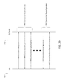
- FIG. 29 is a signaling diagram that illustrates switching between light-weight and legacy connections
- FIG. 30 is a signaling diagram that illustrates switching between light-weight and legacy connections during connection resume.
- FIG. 31A-B are diagrams of Graphical User Interfaces.
- FIG. 32A illustrates one embodiment of an example communications system in which the methods and apparatuses described and claimed herein may be embodied
- FIG. 32B is a block diagram of an example apparatus or device configured for wireless communications in accordance with the embodiments illustrated herein;
- FIG. 32C is a system diagram of an example radio access network (RAN) and core network in accordance with an example embodiment
- FIG. 32D is another system diagram of a RAN and core network according to another embodiment
- FIG. 32E is another system diagram of a RAN and core network according to another embodiment.
- FIG. 32F is a block diagram of an exemplary computing system 90 in which one or more apparatuses of the communications networks illustrated in FIGS. 32A, 32C, 32D and 32E may be embodied.
- FIG. 13 is a diagram that illustrates Legacy System Information (SI) Provisioning.
- SI System Information
- the E-UTRAN 504 repeatedly broadcasts the System Information that is needed by the UEs to be able to access and operate within the network.
- UEs in RRC_IDLE and RRC_CONNECTED modes apply the System Information Acquisition procedure to obtain the required System Information (e.g., MIB, SIB1, SIB2-SIB8, etc.).
- UE 502 can be, for example, an eMBB device 502 a , a low cost MTC device 502 b , or a UR/LL device 502 c.
- the current SI provisioning mechanism in 3GPP where the UE has to acquire the full set of SI broadcast by the eNB although only a small subset of SI changes, increases UE power consumption and will negatively impact the ability of the UE to meet the UE Battery Life requirements of 10 years defined in section 7.11 of TR 38.913.
- the current SI provisioning mechanism in 3GPP where the full set of SI is broadcast whether or not there are UEs within the coverage area of the cell and regardless of if there is update of SIB or not, increases eNB power consumption and will negatively impact the ability of the eNB to meet the Network Energy Efficiency requirements defined in section 7.19 of 3GPP TR 38.913.
- the SIBs For example, in the later evening and early morning, cells covering enterprises, urban hot spots, etc. tend to have fewer UEs in the coverage area. There is also a dependency on the day of the week (e.g., typically less activity on weekends). How often the SIBs change can be deployment specific. In some scenarios, the information contained in the SIBs is relatively static and may remain the same for hours or even days. It is further recognized herein that the current SI provisioning mechanism in 3GPP, where the SI is broadcast in a cell-centric manner without differentiation among different UEs, services and Use Cases, does not support network slicing requirements defined in section 5.2 of 3GPP TR 22.891. This can result in the UE acquiring SIBs that might not be needed to access and operate within a given network slice.
- SI is provisioned on-demand.
- eCell extended cell
- An eCell can be one or a combination of several following entities in the future cellular system.
- an eCell can be a slice of the network or RAN system that is configured for the UE, if RAN slicing based architecture is used. In some cases, the slicing of network or RAN system can be done on a per user case base or using other criteria.
- the eCell can be an umbrella cell that covers one or several cells.
- the eCell can be a Multicast-Broadcast Single-Frequency Network (MBSFN) coverage area that covers one or several cells.
- MMSFN Multicast-Broadcast Single-Frequency Network
- the eCell can include cluster of coordinated cells (e.g., CoMP cells) for a UE.
- the eCell can be a cell as currently defined in the 3GPP standards.
- eCell For the convenience of illustration, the term “eCell” is used throughout the document, though it will be understood that an eCell can be one of the above-described entities or a combination thereof. Each eCell can have its own unique ID, which is referred to as an eCellIdentity (eCell ID). In an example, the eCellIdentity is carried by extending the current SIB1, though it will be understood that the implementation of signaling eCellIdentity in the 5G system is not limited to this example below in accordance with various embodiments.
- SystemInformationBlockType1 SEQUENCE ⁇ cellAccessRelatedInfo SEQUENCE ⁇ plmn-IdentityList PLMN-IdentityList, trackingAreaCode TrackingAreaCode, cellIdentity CellIdentity, cellBarred ENUMERATED ⁇ barred, notBarred ⁇ , intraFreqReselection ENUMERATED ⁇ allowed, notAllowed ⁇ , csg-Indication BOOLEAN, csg-Identity CSG-Identity, OPTIONAL -- Need OR eCellIdentity Extended CellIdentity ⁇ , cellSelectionInfo SEQUENCE ⁇ q-RxLevMin Q-RxLevMin, q-RxLevMinOffset INTEGER (1..8) OPTIONAL -- Need OP ⁇ , p-Max P-Max OPTIONAL, -- Need OP freqBandIndicator FreqBandIndicator, schedulingInfoList SchedulingInfoList, tdd-Config TDD-Config OPTIONAL
- An extended SI value tag is now described in accordance with an example embodiment. Similar to the SI or SIBs in the current 3GPP system, it is recognized herein that the SI elements in the future cellular system are important system information that a UE might need to acquire before it can fully access the network or services/functionalities provided by the network. Defined herein is an extended value tag for system information, called eSystemInfoValueTag, as an index corresponding to a system information configuration parameter set of a particular eCell.
- each eSystemInfoValueTag value corresponds to a different SI configuration parameter set of eCell indentified by a eCellidentity (eCell ID).
- the SI elements in the SI configuration parameter set can exclude dynamic parameters such as, for example, timer or system load that change with system time.
- the length of eSystemInfoValueTag can be N bits, which can index up to 2 N SI configuration parameter sets.
- the eSystemInfoValueTag values and corresponding SI configuration parameter sets of those eCells/cells can be configured (pre-loaded) at the UE through a graphical User Interface (GUI) so that the on-demand SI provisioning can be implemented more efficiently.
- GUI graphical User Interface
- the eSystemInfoValueTag is carried by extending the current SIB1 as an example to illustrate one solution, though it will be understood that the implementation of signaling eSystemInfoValueTag in the 5G system is not limited to this example below in accordance with various embodiments.
- SystemInformationBlockType1 SEQUENCE ⁇ cellAccessRelatedInfo SEQUENCE ⁇ plmn-Identity List PLMN-IdentityList, trackingAreaCode TrackingAreaCode, cellIdentity CellIdentity, cellBarred ENUMERATED ⁇ barred, notBarred ⁇ , intraFreqReselection ENUMERATED ⁇ allowed, notAllowed ⁇ , csg-Indication BOOLEAN, csg-Identity CSG-Identity OPTIONAL -- Need OR eCellIdentity Extended CellIdentity ⁇ , cellSelectionInfo SEQUENCE ⁇ q-RxLevMin Q-RxLevMin, q-RxLevMinOffset INTEGER (1..8) OPTIONAL -- Need OP ⁇ , p-Max P-Max OPTIONAL, -- Need OP freqBandIndicator FreqBandIndicator, schedulingInfoList SchedulingInfoList, tdd-Config TDD-Config OPTIONAL,
- SI system information is divided into MIB and a number of SIBs in a similar manner as in 3GPP LTE Rel-13. It will be appreciated, however, that the methods described herein can be applied to a system where system information is alternatively organized.
- a new SI Block can contain the set of essential SI elements in the future cellular systems.
- the SIBe can be carried in one of several SI blocks in the 5G system.
- the SIBe includes most important system information without which a UE cannot (correctly) access the network.
- the SIBe may include use case specific resources, channel configuration and random access information, etc.
- the SIBe can include the value of current eSystemInfoValueTag and an SIRequestAccess Field.
- An SIRequestAccess field may contain a SIRequestAccess subfield for each use case (for example, but not limited to eMBB, mMTC, UR/LL, etc.).
- the SIRequestAccess subfield of an example Use Case i is used to indicate how a UE of a specific Use Case i is allowed to send an SI Request to the cell.
- the SIRequestAccess subfield uses K, bits to represent the probability that the UE is allowed to transmit an SR Request to the cell, P access (i), where the probability is quantized to 2 Ki levels between [P 1 (i), P 2 (i)]. It is recognized herein that the SIPF already considers factors such as system load, interference, etc. in determining the value of P access (i).
- the system may allocate reserved or pre-defined physical channel resources for UEs to transmit their SI Requests, which can be carried on either RACH, PUCCH or PUSCH, using dedicated channel resources or shared/common/random channel resources.
- the UE will transmit its SI Request to its eCell (identified by eCell ID).
- eCell ID identified by eCell ID
- one or several cells may receive the SI request.
- a UE that receives an SIRequestAccess subfield of User Case i it can transmit an SI Request according to the P access (i).
- a p-persistent aloha approach is implemented to transmit the SI request. For example, for each TTI until it is allowed to transmit an SI Request, the UE can generate a random number uniformly distributed between (0, 1). Then, the UE can compare the random number with P access (i). If the random number is smaller than P access (i), the UE can transmit an SI request.
- a delay is generated according to the P access (i), and a wake up is after the delay of SI Request.
- the delay of SI Request can equal 1/P access (i) where the units are one TTI/sub-frame.
- the SIBe is carried by extending the current SIB1, though it will be understood that implementation of signaling SIBe in the 5G system is not limited to this example below.
- SystemInformationBlockType1 SEQUENCE ⁇ cellAccessRelatedInfo SEQUENCE ⁇ plmn-IdentityList PLMN-IdentityList, trackingAreaCode TrackingAreaCode, cellIdentity CellIdentity, cellBarred ENUMERATED ⁇ barred, notBarred ⁇ , intraFreqReselection ENUMERATED ⁇ allowed, notAllowed ⁇ , csg-Indication BOOLEAN, csg-Identity CSG-Identity OPTIONAL -- Need OR ⁇ , cellSelectionInfo SEQUENCE ⁇ q-RxLevMin Q-RxLevMin, q-RxLevMinOffset INTEGER (1..8) OPTIONAL -- Need OP ⁇ , p-Max P-Max OPTIONAL, -- Need OP freqBandIndicator FreqBandIndicator, schedulingInfoList SchedulingInfoList, tdd-Config TDD-Config OPTIONAL, -- Cond TDD si-WindowL
- SIRequestAccessUseCase 1 ENUMERATED ⁇ P1(1), P2(1), ... , P2k(1) ⁇ SIRequestAccessUseCase 2 ENUMERATED ⁇ P1(2), P2(2), ... , P2k(2) ⁇ ... SIRequestAccessUseCase Q ENUMERATED ⁇ P1(Q), P2(Q), ... , P2k(Q) ⁇ nonCriticalExtension SystemInformationBlockType1-v890-IEs OPTIONAL ⁇ ... -- ASN1STOP
- the network may have different access control parameters for their SI requests.
- the system might not allow mMTC devices to send SI Request frequently. Therefore, the probability of sending SI Request in such a system is lower than in others.
- SIPF SI Provisioning Function
- the SIPF can be a logical function that can be located within an entity that is appropriate for the RAN architecture or RAN slicing configured for a UE.
- the SIPF can maintain a list of SI configuration parameter set(s) and corresponding value(s) of eSystemInfoValueTag, which may including its current eSystemInfoValueTag and previously used eSystemInfoValueTag values, if there are any.
- the SIPF increases the current eSystemInfoValueTag value by one (modulo by 2 N ) and updates its database of SI configuration parameter set.
- a UE can also maintain a list of SI configuration parameter set(s) and corresponding value(s) of eSystemInfoValueTag.
- a UE In current 3GPP standards, a UE considers stored system information to be invalid after 3 hours from the moment it was successfully confirmed as valid. With the usage of eSystemInfoValueTag and database of SI configuration parameter set at both the UE and SIPF sides, a new parameter defined in accordance with an example embodiment. This parameter is referred to herein as a stored SI configuration parameter set validity period, which can be different than the term of “SI validity period” in current 3GPP standards. In an example, the stored SI configuration parameter set validity period can be set to (2 N /32)*SI validity period (3 Hours).
- the SIPF at the network can adjust the frequency of broadcast by switching between several SIBe broadcast periodicity values ⁇ SIBeP(1), SIBeP(i), SIBeP(L) ⁇ (in the ascending order of values) based on the activities in the eCell or demands from the UEs.
- SIBe broadcast periodicity values ⁇ SIBeP(1), SIBeP(i), SIBeP(L) ⁇ (in the ascending order of values) based on the activities in the eCell or demands from the UEs.
- SIBeP(1), SIBeP(i), SIBeP(L) ⁇ in the ascending order of values
- the system information is divided into minimum SI (System Information) and other SI.
- Minimum SI is periodically broadcast.
- the minimum system information may at least include basic information required for initial access (for e.g. information to support cell selection including information required to evaluate whether or not the UE 502 is allowed to access the cell [at node B 1502 ]), information for acquiring other SI and scheduled information for broadcast SI.
- the other SI encompasses everything not broadcasted in minimum SI.
- the other SI may either be broadcast, or provisioned in a dedicated manner, either triggered by the network or upon request from the UE 502 as illustrated in the Figure below.
- the UE 502 needs to know whether it is available in the cell and whether it is broadcast or not (e.g., by checking the minimum SI).
- the UE 502 in RRC_IDLE or RRC_INACTIVE (aka “new NR state”) should be able to request the other SI without requiring a state transition.
- the other SI may be broadcast at configurable periodicity and for certain duration.
- Public Warning System (PWS) information can be classified into the other SI.
- FIG. 15B shows an exemplary use case.
- Pre-configured and stored tags and SI parameter sets are used to minimize SI acquisition overheads for UEs.
- UE 1 uses a GUI to pre-configure tags and SI parameter sets of frequent locations. When UE 1 receives a matching tag from a cell, UE 1 can then use a pre-configured SI parameter set for that tag.
- UE 2 uses stored tags and SI parameter sets from previous connections. When UE 2 receives a matching tag from a cell, UE 2 can then use a stored SI parameter set for that tag.
- UE 3 uses on-demand SI provisioning to help to reduce SI acquisition latency.
- UE 3 can transmit a SI request according to a received parameter, such as a SIRequestAcess parameter. The cell can then respond with the SI parameters. In this case only new parameters are sent and the UE3 updates the stored parameters for the current tag.
- the SIPF at the network starts to broadcast the SIBe using an initial value of SIBe broadcast periodicity, say SIBeP(i).
- the periodicity may be adjusted later on based on the eCell activity, number of received SI requests, etc.
- the eCellidentity the value of current eSystemInfoValueTag and the SIRequestAccessfield can be transmitted.
- the SIPF at the UE determines whether it needs to acquire SI. When a UE is in a state that needs to acquire the SI information (for example, cell selection or re-selection, wakes up from DRX or idle state, etc.), it might need to acquire the SIBe first.
- the process can return to step 1602 . If it does, the process can proceed to step 1604 , where the UE acquires a valid SIBe. Upon successful reception of the SIBe, the UE can perform the one or more of the following (depending on different cases). In accordance with the illustrated example, if the UE has at least one valid SI Configuration set of this cell stored in its SIPF, it can compare the values of eSystemInfoValueTag of those valid SI Configuration set stored locally with the value of eSystemInfoValueTag received in SIBe (at step 1608 ).
- the UE might consider that it has acquired the valid system information (at step 1609 ). Thus, the UE might apply the SI Configuration set corresponding to the matched eSystemInfoValueTag to its current system information in the cell. The UE can update the value of current eSystemInfoValueTag with the value of eSystemInfoValueTag received in SIBe, and store the previous value in the stored valid eSystemInfoValueTag.
- the UE can check the SIRequestAccess field received in the SIBe, and send a SI Request, at step 1610 , according to the parameters in the SIRequestAccess sub-field.
- the SI Request sent to the eCell by the UE may contain the most recent valid eSystemInfoValueTag that the UE stored locally (e.g., before it entered DRX, idle state, handover, etc.).
- the UE may specify a maximum amount of time it can wait for SI acquisition (MaxTimeSIAcquisition). The value of this parameter can be determined by the UE based on its use case, applications, and corresponding requirements (e.g., latency and power savings/consumptions).
- the UE may specify a list of SI elements that it wants to acquire (e.g., the list can be much shorter than all SIBs that eNB typically broadcast in current standards).
- the UE may list some cell selection criteria as well, for example. If the UE does not have any valid SI Configuration set of this cell stored in its SIPF, it can check the SIRequestAccess field received in the SIBe, and send a SI Request according to the parameters in the SIRequestAccess sub-field.
- the SI Request sent to the eCell by the UE may specify a list of SI elements that it wants to acquire (e.g., the list could be much shorter than all SIBs that eNB typically broadcast in current standards). It may lists some cell selection criteria as well.
- the UE may specify a maximum amount of time it can wait for SI acquisition (MaxTimeSIAcquisition).
- the SIPF at the network receives the SI Request.
- the SIPF may process in accordance with the illustrated example. For example, at step 1614 , for a received SI Request with an eSystemInfoValueTag included in it, the SIPF compares its current eSystemInfoValueTag with the received eSystemInfoValueTag. If the two eSystemInfoValueTag values are the same, an eNB or the like, at step 1615 , can send an SI response that includes a confirmation for the matched tag and the dynamic SI elements that the UE wants to acquire (e.g., which can be specified in the UE's SI Request).
- an eNB or the like can send, at step 1616 , an SI response which includes the value of current eSystemInfoValueTag, the different parts of SI configuration sets of these two corresponding eSystemInfoValueTags, and the dynamic SI elements that the UE wants to acquire (e.g., specified in the UE's SI Request).
- the SIPF can send a SI response which includes the value of current eSystemInfoValueTag, the SI elements that the UE wants to acquire (e.g. specified in the UE's SI Request).
- the SIPF can delay the processing of the received SI Request as long as its response to the SI Request is within the window specified by MaxTimeSIAcquisition in the received SI Request.
- the SIPF can process them and merge the required SI responses jointly to save radio resources.
- the SIPF can transmit the SI response on the downlink (data) channel with a common RNTI (e.g., such as SI-RNTI) to allow multiple UEs to acquire these SI elements.
- a common RNTI e.g., such as SI-RNTI
- the SIPF may switch the on-demand SI provisioning mode to the conventional SI broadcast, as described herein.
- the UE determines whether it has received at least one SI response. If the UE does not receive at least one SI response or other SIBs (SIBs update) within MaxTimeSIAcquisition, it can delay (at step 1623 ) for a pre-defined SI Request Retry Period, and re-transmit its SI Request according to the received SIRequestAccess field. If the UE receives at least one SI response within MaxTimeSIAcquisition, the process can proceed to step 1624 . Upon reception of SI Response or other SIBs (or SIBs update) from the SIPF, the UE can update its database of SI configuration sets and corresponding values of eSystemInfoValueTag.
- the UE can apply the received SI elements to its valid SI configuration, and update its current value of eSystemInfoValueTag to be the received tag value.
- the SIPF at the network can adjust the SIBe broadcast periodicity, or switch back to full SI broadcast mode based on, for example, the number of SI requests received during the past one or more SIBe broadcast periods.
- Normal/Reduced SI Broadcast an eNB/cell can be triggered to switch from normal to reduced SI broadcast and visa-versa.
- the On-Demand SI provisioning mechanisms described above can be used in a cell that is configured for either SI Broadcast level.
- triggering mechanism is based on a schedule, such as date/time-of-day.
- the SI Broadcast Level can be configured to be “Reduced” during the time of day when the service demand is expected to be low and “Normal” when the service demand is expected to be higher.
- a dynamic approach based on the activity level within the cell can also be defined. For example, when configured for “Normal” SI broadcast, an activity level below a threshold can be used to trigger a transition to a “Reduced” SI broadcast. Further, when configured for a “Reduced” SI broadcast, an activity level above a threshold can be used to trigger a transition to “Normal” SI broadcast.
- the eNB/cell is initialized to the default SI Broadcast Level, which can be “Normal” or “Reduced”.
- the eNB/cell then broadcasts the SI according to the configured SI Broadcast Level for a period of time that corresponds to the SI Broadcast Level Modification Period.
- the SI Broadcast Modification Period coincides with the BCCH Modification Period.
- the SI Broadcast Modification Period can be defined independent of the BCCH Modification Period.
- an activity level can be estimated, which can be referred to as an ActivityIndex.
- the ActivityIndex is determined based on metrics that represent the number of UEs in RRC_IDLE and/or RRC_CONNECTED at a given time. Alternatively, or additionally the ActivityIndex can be based on metrics such as the number of PRACH attempts, paging attempts, Tracking Area Updates (TAU), System Information Requests, etc. that occur during a given estimation interval (TEST_INT).
- TEST_INT is aligned with the boundaries of the SI Broadcast Level Modification Period. Alternatively, the estimation interval TEST_INT can be shorter or longer than the SI Broadcast Level Modification Period and might not be aligned with the boundaries of the SI Broadcast Level Modification Period.
- An exemplary set of ActivityMetrics used to determine the ActivityIndex can be defined as follows, without limitation:
- the ActivityIndex can be based on one or more of these ActivityMetrics, where each ActivityMetric is optionally scaled by a weighting factor that can be used to adjust the relative weight of a given ActivityMetric, for example;
- ActivityIndex ⁇ All ⁇ ⁇ ActivityMetrics ⁇ w i ⁇ ActivityMetric i
- the ActivityIndex can be compared with the low activity threshold (ActivityLowThresh) and the high activity threshold (ActivityHighThresh), respectively. If the ActivityIndex is less than ActivityLowThresh, the SI Broadcast Level for the next SI Broadcast Modification Period can be set to “Reduced” at step 1712 . If the ActivityIndex is greater than ActivityHighThresh, the SI Broadcast Level for the next SI Broadcast Modification Period can set to “Normal” at step 1714 . Otherwise, the process can return to step 1704 and the SI Broadcast Level for the next SI Broadcast Modification Period can be the same as what was used in the current SI Broadcast Modification Period.
- the thresholds are configurable and could be tuned over time to make the system more or less responsive to instantaneous changes in the activity level.
- the eNB/cell broadcasts the SI according to the new SI Broadcast Level, which is set at step 1702 , for a period of time that corresponds to the SI Broadcast Level Modification Period.
- the process of estimating the activity (step 1706 ), determining the SI Broadcast Level, and reconfiguring the SI Broadcast Level can then repeat.
- An extended value tag for system information is defined, where each of such value tags correspond to a system information configuration parameter set of a cell.
- An entity that can be responsible for SI provisioning in a cell or the equivalent of a cell in the future cellular system is defined as a SI Provisioning Function (SIPF).
- SIPF and UE can utilize extended value tag to perform on-demand SI provisioning.
- normal or reduced SI broadcasts can be triggered based time or activity levels within a cell. For example, an activity index can be determined, and the activity index can be compared to various thresholds. The SI broadcast level can be modified based on the comparison.
- FIG. 18 is a diagram that illustrates cells (small cells 1802 and large cell 1804 ) that makeup common areas (cluster 1 and cluster 2).
- Cluster 1 is made of small cells
- cluster 2 is made of a large cell and several small cells.
- IEs Information Elements
- the set of cells that makeup the Common Area may be from the same layer or different layers; e.g. small cell layer, macro layer, as shown in FIG. 18 .
- FIG. 18 may be implemented in the form of software (i.e., computer-executable instructions) stored in a memory of, and executing on a processor of, a wireless device or other apparatus (e.g., a server, gateway, device, or other computer system), such as one of those illustrated in FIGS. 32B and F described below.
- software i.e., computer-executable instructions
- a wireless device or other apparatus e.g., a server, gateway, device, or other computer system
- FIG. 19A is a flow chart that illustrates a system information acquisition procedure.
- step 1910 upon entering a second cell region associated with a second cell from a first cell region associated with a first cell, a broadcast message can be received indicative of a cluster identity associated with the second cell.
- the SI broadcast by a cell may include an IE that is used to indicate to which cluster the cell belongs; e.g. a cluster-Identity IE.
- the cluster identity could be indicated implicitly using an existing IE such as the cellIdentity signaled in SIB1; e.g. one or more bits in the cellIdentity could be used to indicate the cluster to which the cell belongs.
- a cluster-Identity IE it could be included in an existing SIB, e.g. SIB1, SIB2, etc. or a new SIB could be defined to carry this IE, on its own or together with new or existing IEs.
- the SI broadcast by a cell may also include one or more IEs to indicate if a SIB is “cell specific” or “common” to the cluster.
- SIB1 could include cluster-Identity and sib-CommonInfo IEs defined as shown below.
- step 1912 it is determined if cluster identity associated with the second cell the same as a cluster identity associated with the first cell.
- the UE 502 before acquiring the System Information of the new serving cell following cell reselection, the UE 502 compares the cluster-Identity of the new serving cell with the cluster-Identity of the prior serving cell. If they are the same, then only the cell-specific SIBs need to be acquired from the new serving cell (in step 1914 ). The UE 502 checks the value of the sib-CommonInfo IE for a given SIB to determine if it is a common SIB or a cell-specific SIB.
- the UE 502 uses the System Information Acquisition procedure defined in section 5.2.3 of 3GPP TS 36.331 to acquire SI messages to which a cell-specific SIB is mapped. If the new serving cell belongs to a different cluster, then the UE 502 acquires all the required SIBs from new serving cell (in step 1916 ).
- the broadcast period for some of the SIBs that may need to be acquired can be hundreds of milliseconds.
- the UE 502 can send a System Information Request message to the eNB/cell (Cell 1 (cell 1902 ) and Cell 2 (cell 1904 )) as shown in FIG. 19B .
- the signaling shown in FIG. 19B shows the MIB, SIB1 and SIB2 of Cell 2 (cell 1904 ) being acquired before performing the cell reselection evaluation process. If SIB2 is a common SIB, it may not need to be acquired prior to performing the cell reselection evaluation process.
- FIGS. 19A and 19B may be logical entities that may be implemented in the form of software (i.e., computer-executable instructions) stored in a memory of, and executing on a processor of, an apparatus configured for wireless and/or network communications or a computer system such as those illustrated in FIGS. 32B and F. That is, the method(s) illustrated in FIGS. 19A and 19B may be implemented in the form of software (i.e., computer-executable instructions) stored in a memory of an apparatus, such as the apparatus or computer system illustrated in FIGS. 32B and F, which computer executable instructions, when executed by a processor of the apparatus, perform the steps illustrated in FIGS. 19A and 19B . It is also understood that any transmitting and receiving steps illustrated in FIGS. 19A and 19B may be performed by communication circuitry of the apparatus under control of the processor of the apparatus and the computer-executable instructions (e.g., software) that it executes.
- any transmitting and receiving steps illustrated in FIGS. 19A and 19B may
- the eNB includes all the common SIBs in the SystemInformationResponse message.
- the SystemInformationRequest message may include a field or fields to indicate which common SIBs should be included in the SystemInformationRequest message.
- the System Information Request may not be supported by all eNB/cells in network. Therefore, the SI broadcast by the cell may include an IE that indicates whether or not the cell supports the System Information Request. In one embodiment, a new IE called SysInfoReqAllowed could be optionally included in SIB1 to indicate System Information Request messages are allowed in the cell.
- RRC connection setup is the main contributor to the high signaling load. As shown in FIG. 20 , in one study the RRC connection setup comprises 51.4% of the signaling load.
- the new 5G systems specification initiative in 3GPP offers the opportunity to explore novel ideas without backward compatibility constraints for signaling load reduction in the next generation networks.
- Node B or eNode B or 5G RAN node are used to generically denote a 5G Radio Access Network Node, which could be either located in the control plane, or in the user plane, and could be located in a centralized location (e.g. data center, cloud, i.e. central controller or central unit in support of virtualization) or could be located at the edge of the RAN as a distributed RAN unit for e.g. a Transmit Reception Point (TRP) with RAN functions located at the edge of the RAN.
- TRP Transmit Reception Point
- MME Mobile Management Entity
- 5G CN control node are used generically in reference, to a 5G network control entity or control unit located in the control plane.
- S-GW, P-GW or 5G core network equivalent node are used in reference to 5G core network gateway or user data processing unit located in the data plane or user plane.
- DRB Data radio Bearer
- SRB Signaling Radio Bearer
- An index-based Access Stratum (AS) configuration procedure can be an extension of the legacy RRC Connection Control procedures; e.g. RRC Connection Establishment, RRC Connection Reconfiguration.
- FIG. 21A An exemplary framework for index-based configuration is shown in FIG. 21A .
- a novel index-based connection establishment procedure can be used to establish the required Radio Bearers (RB); e.g. SRB, DRB.
- RB Radio Bearers
- An N-bit configuration index can be signaled to/from the UE 502 and used to “lookup” the corresponding set of configuration parameters needed to establish the connection, where the value N is dependent on the number of configurations that need to be supported.
- the same index can be signaled between the radio access node 1502 (or eNB) and Core Network (CN) nodes 2106 ; e.g.
- CN Core Network
- MME Mobility Management Entity
- S-GW Serving Mobility Management Entity
- P-GW P-GW in the Evolved Packet Core (EPC) or NexGen_CN_Control_Node and NexGen_CN_Data_Plane nodes in a 5G network, and used to “lookup” the corresponding set of configuration parameters needed by the nodes.
- the index values can be used to obtain configuration information from memory locations such as configuration databases 2108 , 2110 and 2112 .
- the UE 502 may provide a single configuration index toward the network (radio access node 1502 or core node 2106 ) or provide more than one configuration index toward the network.
- the network in its response to the UE 502 , might use any or a subset of the configuration index from the UE 502 or an index or index set completely different from the one(s) suggested by the UE 502 .
- the UE 502 need not provide any configuration index in the connection setup request toward the network.
- the network in its response to the UE 502 may provide one or more configuration index(es) to UE.
- the network has the ability to initiate the setup of a light connection procedure between the network and the UE 502 and is not necessarily bound to the presence of a configuration index in the request message from the UE 502 .
- the network may initiate the procedure on its own for e.g. for reconfiguration an existing connection whether it is an existing legacy connection between the UE 502 and the network or an existing light-weight connection between the UE 502 and the network.
- FIG. 21B illustrates an example that illustrates how the configuration parameters for the different layers in the radio communication stack including physical layer (PHY), Media Access Control (MAC), Radio Link Control (RLC), Packet Data Convergence Protocol (PDCP), and Radio Resource Control (RRC) that are obtained using an index.
- PHY physical layer
- MAC Media Access Control
- RLC Radio Link Control
- PDCP Packet Data Convergence Protocol
- RRC Radio Resource Control
- the UE 502 , radio access node 1502 , and core network node 2106 can be, or be implemented on, an apparatus including a processor and a memory.
- the apparatus including computer-executable instructions stored in the memory of the apparatus which, when executed by the processor of the apparatus, cause the apparatus to use an index value to look up a configuration parameters for a connection.
- the configuration parameters can be used to set up a connection.
- FIGS. 21A-B may be implemented in the form of software (i.e., computer-executable instructions) stored in a memory of, and executing on a processor of, a wireless device or other apparatus (e.g., a server, gateway, device, or other computer system), such as one of those illustrated in FIGS. 32B and F described below.
- a wireless device or other apparatus e.g., a server, gateway, device, or other computer system
- FIG. 22 An exemplary Light-Weight Connection Establishment signaling diagram is shown in FIG. 22 .
- the number of exchanged messages can be as small as 3 messages, each with a size as small as 6 octets.
- Such Light-Weight Connection Establishment signaling can replace intensive signaling of the legacy procedure for SRB and DRB setup shown in FIG. 13 .
- the UE 502 initiates the procedure by transmitting the LW-ConnectionRequest message, which is defined as shown below.
- the LW-ConnectionRequest message includes the ue-Identity and optionally includes a cfgIndex, where the cfgIndex may be used to indicate the UE's preferred configuration.
- the UE 502 may signal a cfgIndex list where the list may be used to indicate the UE's preferred configurations thereby enabling the network to select a configuration from the list of preferred configurations.
- the eNB (radio access node 1502 ) responds with a LW-ConnectionSetup message as defined below.
- the LW-ConnectionSetup message optionally includes a cfgIndex that is used to indicate the network selected configuration, where the selected configuration may or may not correspond to a UE 502 preferred configuration.
- the eNB may omit the cfgIndex, thereby implying the network selected the UE 502 preferred configuration signaled by the UE 502 in the LW-ConnectionRequest message.
- the eNB may respond with a cfgIndex list, where the list corresponds to a set of allowed configurations, thereby enabling the UE 502 to select a preferred configuration from the list.
- the UE 502 Upon reception of the LW-ConnectionSetup message the UE 502 can apply the selected configuration as follows:
- the UE 502 After successfully applying the selected configuration, the UE 502 responds with a LW-ConnectionSetupComplete message as defined below.
- the LW-ConnectionSetupComplete message includes a cfgIndex to indicate the configuration that was selected and successfully applied by the UE 502 .
- the LW-ConnectionSetupComplete message may optionally include the mobilityState, where the mobility state of the UE 502 is determined as defined TS 36.304.
- the entities performing the steps illustrated in FIG. 22 may be logical entities that may be implemented in the form of software (i.e., computer-executable instructions) stored in a memory of, and executing on a processor of, an apparatus configured for wireless and/or network communications or a computer system such as those illustrated in FIGS. 21B and F. That is, the method(s) illustrated in FIG. 22 may be implemented in the form of software (i.e., computer-executable instructions) stored in a memory of an apparatus, such as the apparatus or computer system illustrated in FIGS. 32B and F, which computer executable instructions, when executed by a processor of the apparatus, perform the steps illustrated in FIG. 22 . It is also understood that any transmitting and receiving steps illustrated in FIG. 22 may be performed by communication circuitry of the apparatus under control of the processor of the apparatus and the computer-executable instructions (e.g., software) that it executes.
- software i.e., computer-executable instructions
- the solution is described in terms of SRB or DRB system parameters pre-configuration, the solution is equally applicable to pre-configuration of data flow or pre-configuration of IP flow, or pre-configuration of logical channel or any other pre-configuration of system parameters that can be used to configure the protocol stack (including the PHY) in each node of the system (including the UE 502 ) without having to explicitly signal all or nearly all the configuration parameters over the air interface.
- the RRC Connection Establishment procedure is used to establish a connection between the UE 502 and the E-UTRAN 504 . Execution of this procedure involves establishment of SRB1 and transferring the initial NAS dedicated information/message from the UE 502 to the E-UTRAN 504 .
- the RRC Connection Reconfiguration procedure is used to establish additional Radio Bearers (RBs); e.g. SRB2, DRBs, so data can be transmitted/received on the user plane.
- RBs Radio Bearers
- the main contributor to the signaling overhead in these procedures is the RRCConnectionSetup and RRCConnectionReconfiguration messages.
- a mechanism to signal an indicator or indicators that can be used to “lookup” the set of configuration parameters used to setup the necessary RBs and to optionally modify the MAC main configuration, the SPS configuration and/or the dedicated physical configuration To reduce the payload size of the RRCConnectionSetup and RRCConnectionReconfiguration messages, and thereby reduce the signaling overhead for light-weight connections, a mechanism to signal an indicator or indicators that can be used to “lookup” the set of configuration parameters used to setup the necessary RBs and to optionally modify the MAC main configuration, the SPS configuration and/or the dedicated physical configuration.
- the Configuration DB may contain multiple configuration sets used for configuration of the RBs and lower layers. This could be based off the default radio configurations defined in section 9.2 of 36.331 (V13.1.0).
- the configuration sets for the RBs/lower layers may be based on the IEs signaled in the legacy RadioResourceConfigDedicated IE as shown below:
- the solution is described in terms of SRB or DRB system parameters pre-configuration, the solution is equally applicable to pre-configuration of data flow or pre-configuration of IP flow, or pre-configuration of logical channel or any other pre-configuration of system parameters that can be used to configure the protocol stack (including the PHY) in each node of the system (including the UE 502 ) without having to explicitly signal all or nearly all the configuration parameters over the air interface.
- the EstablishmentCause field signaled in the RRCConnectionRequest message provides the establishment cause for the RRC connection request.
- the RRC connection establishment cause may be used for differentiated handling of data and signaling in the AS.
- the definition of the EstablishmentCause IE can be extended to include a new cause that enables the use of index-based UE configuration for light-weight connections. An exemplary Extended Establishment Cause IE is described below.
- EstablishmentCause ENUMERATED ⁇ emergency, highPriorityAccess, mt-Access, mo-Signalling, mo-Data, delayTolerantAccess-v1020, mo-VoiceCall-v1280, light-weight ⁇ -- ASN1STOP Definition of Extended RRC Connection Setup Message
- the RRCConnectionSetup message is extended to optionally include a set of configuration index fields that can be used to “lookup” the set of configuration parameters used to setup SRB1 and modify the MAC main configuration and/or the dedicated physical configuration.
- the exemplary extension includes configuration index fields for SRB1, MAC, and PHY, index-based configuration can be used for any combination of these entities/functions.
- the range of the configuration index fields in the example provides support for up to 4 different configurations; i.e. configurations 0-3. This range can be extended or reduced to support the desired number of configurations.
- An exemplary Extended RRCConnectionSetup message is described below.
- RRCConnectionSetup SEQUENCE ⁇ rrc-TransactionIdentifier
- cfgIndex field could be used, where a specified set of bits in the field corresponds to the configuration index for the various entities/functions.
- An exemplary encoding of a 6-bit cfgIndex field is shown in Table 1.
- RRCConnectionSetup SEQUENCE ⁇ rrc-TransactionIdentifier
- criticalExtensions CHOICE ⁇ c1 CHOICE ⁇ rrcConnectionSetup-r8 RRCConnectionSetup-r8- IEs, spare7 NULL, spare6 NULL, spare5 NULL, spare4 NULL, spare3 NULL, spare2 NULL, spare1 NULL ⁇ , cfgIndex Integer (0..63), criticalExtensionsFuture
- SEQUENCE ⁇ ⁇ ⁇ ⁇ ⁇ RRCConnectionSetup-r8-IEs :: SEQUENCE ⁇ radioResourceConfigDedicated RadioResourceConfigDedicated, nonCriticalExtension
- RRCConnectionSetup-v8a0-IEs OPTIONAL ⁇
- RRCConnectionSetup-v8a0-IEs SEQUENCE ⁇ lateNonCriticalExtension OCTET STRING OPTIONAL, nonC
- the RadioResourceConfigDedicated IE is extended to include configuration index fields that can be optionally provided to devices that require light-weight connections.
- configuration index fields that can be optionally provided to devices that require light-weight connections.
- support for index-based configuration is provided for the RB configurations, MAC main configuration, SPS configuration and dedicated physical configuration.
- index-based configuration is supported for any combination of these entities/functions.
- the range of cfgIndex field in the example provides support for up to 4 different configurations; i.e. configurations 0-3. This range can be extended or reduced to support the desired number of configurations.
- the UE 502 When the UE 502 receives an RRC message with the extended RadioResourceConfigDedicated IE containing a cfgIndex field, it uses the cfgIndex to lookup the configuration parameters from a local database containing configuration parameter sets as shown in FIG. 23 .
- the configuration database may contain configuration parameter sets for the RBs, the MAC main configuration, the SPS configuration and/or the dedicated physical configuration.
- FIG. 23 may be implemented in the form of software (i.e., computer-executable instructions) stored in a memory of, and executing on a processor of, a wireless device or other apparatus (e.g., a server, gateway, device, or other computer system), such as one of those illustrated in FIGS. 32B and F described below.
- software i.e., computer-executable instructions
- a wireless device or other apparatus e.g., a server, gateway, device, or other computer system
- RadioResourceConfigDedicated SEQUENCE ⁇ srb-ToAddModList SRB-ToAddModList OPTIONAL, -- Cond HO-Conn drb-ToAddModList DRB-ToAddModList OPTIONAL, -- Cond HO-toEUTRA drb-ToReleaseList DRB-ToReleaseList OPTIONAL, -- Need ON mac-MainConfig CHOICE ⁇ explicitValue MAC-MainConfig, defaultValue NULL, cfgIndex Integer (0..3) ⁇ OPTIONAL, -- Cond HO-toEUTRA2 sps-Config CHOICE ⁇ explicitValue SPS-Config, cfgIndex Integer (0..3) ⁇ OPTIONAL, -- Need ON physicalConfigDedicated Choice ⁇ explicitValue PhysicalConfigDedicated, cfgIndex Integer (0..3) ⁇ OPTIONAL, -- Need ON ..., [[ rl
- ⁇ P-a :: ENUMERATED ⁇ dB-6, dB-4dot77, dB-3, dB-1dot77, dB0, dB1, dB2, dB3 ⁇ -- ASN1STOP RRC Connection Establishment Using Index-Based AS Configuration
- An RRC Connection Establishment procedure can make use of the index-based AS configuration mechanisms to signal an indicator or indicators that can be used to “lookup” the set of configuration parameters used to setup SRB1 and optionally modify the MAC main configuration and/or the dedicated physical configuration.
- An exemplary RRC Connection Establishment signaling diagram is shown in FIG. 24 .
- the entities performing the steps illustrated in FIG. 24 are logical entities that may be implemented in the form of software (i.e., computer-executable instructions) stored in a memory of, and executing on a processor of, an apparatus configured for wireless and/or network communications or a computer system such as those illustrated in FIGS. 32 B and F. That is, the method(s) illustrated in FIG. 24 may be implemented in the form of software (i.e., computer-executable instructions) stored in a memory of a communications apparatus, such as the apparatus or computer system illustrated in FIGS. 32 B and F, which computer executable instructions, when executed by a processor of the apparatus, perform the steps illustrated in FIG. 24 . It is also understood that any transmitting and receiving steps illustrated in FIG. 24 may be performed by communication circuitry of the apparatus under control of the processor of the apparatus and the computer-executable instructions (e.g., software) that it executes.
- software i.e., computer-executable instructions
- a UE 502 requiring a light-weight connection initiates the RRC Connection Establishment procedure by transmitting an RRCConnectionRequest message to the E-UTRAN 504 .
- the UE 502 sets the contents of the RRCConnectionRequest message and submits it to lower layers for transmission in accordance with the steps defined in section 5.3.3.3 of 3GPP TS 36.331, where the establishmentCause provided by upper layers is ‘light-weight’.
- the E-UTRAN 504 responds with an Extended RRCConnectionSetup message with the fields populated as shown in Table 2.
- the UE 502 executes the steps defined in section 5.3.3.4 of 3GPP TS 36.331, which are modified to include the additional step(s) to “look up” the dedicated configuration parameters for SRB1, the MAC and the PHY.
- the UE 502 responds with an RRCConnectionSetupComplete message with the contents set as described in section 5.3.3.4 3GPP TS 36.331.
- index-based UE configuration using the extended RadioResourceConfigDedicated IE is further illustrated with a connection setup example that makes use of the RRC Connection Establishment and RRC Connection Reconfiguration procedures.
- An exemplary signaling diagram is shown in FIG. 25 .
- the entities performing the steps illustrated in FIG. 25 are logical entities that may be implemented in the form of software (i.e., computer-executable instructions) stored in a memory of, and executing on a processor of, a network apparatus or computer system such as those illustrated in FIGS. 32 B and F. That is, the method(s) illustrated in FIG. 25 may be implemented in the form of software (i.e., computer-executable instructions) stored in a memory of a network apparatus, such as the apparatus or computer system illustrated in FIGS. 32 B and F, which computer executable instructions, when executed by a processor of the apparatus, perform the steps illustrated in FIG. 25 . It is also understood that any transmitting and receiving steps illustrated in FIG. 25 may be performed by communication circuitry of the apparatus under control of the processor of the apparatus and the computer-executable instructions (e.g., software) that it executes.
- software i.e., computer-executable instructions
- the RRC Connection Procedure is initiated by a UE 502 requiring a light-weight connection.
- the UE 502 sets the contents of the RRCConnectionRequest message and submits it to lower layers for transmission in accordance with the steps defined in section 5.3.3.3 of 3GPP TS 36.331.
- the E-UTRAN 504 responds with an RRCConnectionSetup message that includes the extended RadioResourceConfigDedicated IE with the fields populated as shown in Table 3.
- the UE 502 executes the steps defined in section 5.3.3.4 of 3GPP TS 36.331, which are modified to include the additional step(s) to “look up” the dedicated configuration parameters for SRB1, the MAC and the PHY.
- the UE 502 responds with an RRCConnectionSetupComplete message with the contents set as described in section 5.3.3.4 3GPP TS 36.331.
- the E-UTRAN 504 initiates the Initial Security Activity procedure in accordance with section 5.3.4 of 3GPP TS 36.331. This procedure consists of transmission of the SecurityModeCommand message from the E-UTRAN followed by transmission of the SecurityModeComplete message from the UE 502 .
- the E-UTRAN 504 then initiates the RRC Configuration Reconfiguration procedure to establish SRB2 and the required DRBs.
- This procedure consists of transmission of the RRCConnectionReconfiguration message that includes the extended RadioResourceConfigDedicated IE with the fields populated as shown in Table 3.
- the UE 502 executes the steps defined in section 5.3.5.3 of 3GPP TS 36.331, which are modified to include the additional step(s) to “look up” the dedicated configuration parameters.
- SRB2 and a single DRB are setup using the RRC Reconfiguration procedure.
- the SRB1, MAC and PHY configurations are unchanged.
- Stage 2 and Stage 3 agreements reached on NB-IOT include RRC enhancements to support efficient signaling for devices requiring frequent small data transmissions.
- the User Plane Solution documented as Solution 18 in TR 23.720, realizes the signaling overhead reduction by introducing two new procedures RRC Suspend and RRC Resume.
- the UE 502 initiates the RRC Connection Resume procedure by transmitting the RRCConnectionResumeRequest message.
- the E-UTRAN 504 responds by sending an RRCConnectionResumeComplete message.
- the Extended RadioResourceConfigDedicated IE can be optionally included in this messages for devices that require reconfiguration.
- the UE 502 responds with an RRCConnectionReconfigurationComplete message to indicate the configuration was applied successfully.
- An exemplary signaling diagram is shown in FIG. 26 .
- the entities performing the steps illustrated in FIG. 26 may be logical entities that may be implemented in the form of software (i.e., computer-executable instructions) stored in a memory of, and executing on a processor of, an apparatus configured for wireless and/or network communications or a computer system such as those illustrated in FIGS. 32B and F. That is, the method(s) illustrated in FIG. 26 may be implemented in the form of software (i.e., computer-executable instructions) stored in a memory of an apparatus, such as the apparatus or computer system illustrated in FIGS. 32 B and F, which computer executable instructions, when executed by a processor of the apparatus, perform the steps illustrated in FIG. 26 . It is also understood that any transmitting and receiving steps illustrated in FIG. 26 may be performed by communication circuitry of the apparatus under control of the processor of the apparatus and the computer-executable instructions (e.g., software) that it executes.
- software i.e., computer-executable instructions
- the solution is equally applicable to reconfiguration of data flow or reconfiguration of IP flow, or any other reconfiguration of system parameters that can be used to configure the protocol stack (including the PHY) in each node of the system (including the UE 502 ) without having to explicitly signal all or nearly all the configuration parameters over the air interface.
- the triggers for establishing a light-weight signaling connection are described.
- the UE 502 higher layers determine the connection type based on the amount of data, traffic profile, etc. For data packets with a size below a given threshold or for specific traffic profiles, higher layers command the lower layers to establish a light-weight signaling connection. The lower layers may then use one of the mechanisms described above to establish the light-weight connection.
- FIG. 27 is an exemplary signaling diagram that shows the triggering of the LW Connection Establishment procedure in response to the arrival of a “small data” packet.
- the entities performing the steps illustrated in FIG. 27 are logical entities that may be implemented in the form of software (i.e., computer-executable instructions) stored in a memory of, and executing on a processor of, a network apparatus or computer system such as those illustrated in FIGS. 32 B and F. That is, the method(s) illustrated in FIG. 16 may be implemented in the form of software (i.e., computer-executable instructions) stored in a memory of a network apparatus, such as the apparatus or computer system illustrated in FIGS. 32 B and F, which computer executable instructions, when executed by a processor of the apparatus, perform the steps illustrated in FIG. 27 . It is also understood that any transmitting and receiving steps illustrated in FIG. 27 may be performed by communication circuitry of the apparatus under control of the processor of the apparatus and the computer-executable instructions (e.g., software) that it executes.
- software i.e., computer-executable instructions
- FIG. 28 is an exemplary signaling diagram that shows the triggering of the RRC Connection Establishment Using Index-Based AS Configuration procedure in response to the arrival of a “small data” packet.
- the establishmentCause is set to ‘light-weight’ by higher layers and then signaled in the RRCConnectionRequest message.
- the entities performing the steps illustrated in FIG. 28 are logical entities that may be implemented in the form of software (i.e., computer-executable instructions) stored in a memory of, and executing on a processor of, a network apparatus or computer system such as those illustrated in FIGS. 32 B and F. That is, the method(s) illustrated in FIG. 28 may be implemented in the form of software (i.e., computer-executable instructions) stored in a memory of a network apparatus, such as the apparatus or computer system illustrated in FIGS. 32 B and F, which computer executable instructions, when executed by a processor of the apparatus, perform the steps illustrated in FIG. 28 . It is also understood that any transmitting and receiving steps illustrated in FIG. 28 may be performed by communication circuitry of the apparatus under control of the processor of the apparatus and the computer-executable instructions (e.g., software) that it executes.
- software i.e., computer-executable instructions
- the RRC Connection Reconfiguration procedure can be used to modify an existing RRC connection.
- An Extended RadioResourceConfigDedicated IE can include configuration index fields that may be optionally provided to devices that require light-weight connections.
- the Extended RadioResourceConfigDedicated IE in the RRCConnectionReconfiguration message can trigger a switch between light-weight and legacy connections.
- FIG. 29 An exemplary signaling diagram for switching between light-weight and legacy connections is shown in FIG. 29 , where the RRC Configuration Reconfiguration procedure is assumed to be initiated at some time in the future, but while the connection is still established.
- the entities performing the steps illustrated in FIG. 29 are logical entities that may be implemented in the form of software (i.e., computer-executable instructions) stored in a memory of, and executing on a processor of, a network apparatus or computer system such as those illustrated in FIGS. 32 B and F. That is, the method(s) illustrated in FIG. 29 may be implemented in the form of software (i.e., computer-executable instructions) stored in a memory of a network apparatus, such as the apparatus or computer system illustrated in FIGS. 32 B and F, which computer executable instructions, when executed by a processor of the apparatus, perform the steps illustrated in FIG. 29 . It is also understood that any transmitting and receiving steps illustrated in FIG. 29 may be performed by communication circuitry of the apparatus under control of the processor of the apparatus and the computer-executable instructions (e.g., software) that it executes.
- software i.e., computer-executable instructions
- the UE 502 establishes a light-weight connection in accordance with the RRC Connection Establishment Using Index-Based AS Configuration procedure.
- the E-UTRAN 504 signals the UE 502 to use a legacy connection by initiating the RRC Connection Reconfiguration procedure, where the RRCConnectionReconfiguration message transmitted by the E-UTRAN 504 makes use of the legacy mechanisms in the Extended RadioResourceConfigDedicated IE to signal the configuration to the UE 502 .
- the legacy RadioResourceConfigDedicated IE could be used to signal the configuration to the UE 502 .
- the UE 502 Upon reception of this message, the UE 502 executes the steps defined in section 5.3.5.3 of 3GPP TS 36.331. After successfully applying the new configuration, the UE 502 transmits the RRCConnectionReconfigurationComplete message.
- the E-UTRAN 504 may initiate RRC Connection Reconfiguration procedure at a later time to switch back to a light-weight connection.
- the UE 502 establishes a legacy connection in accordance with the RRC Connection Establishment procedure described in section 5.3.3.3 of 3GPP TS 36.331, where the establishmentCause provided by upper layers is set to a value other than ‘light-weight’.
- the E-UTRAN 504 signals the UE 502 to use a light-weight connection by initiating the RRC Connection Reconfiguration procedure, where the RRCConnectionReconfiguration message transmitted by the E-UTRAN 504 includes the Extended RadioResourceConfigDedicated IE with the fields populated as shown in Table 1.
- the UE 502 executes the steps defined in section 5.3.5.3 of 3GPP TS 36.331, which are modified to include the additional step(s) to “look up” the dedicated configuration parameters. After successfully applying the new configuration, the UE 502 transmits the RRCConnectionReconfigurationComplete message.
- the E-UTRAN 504 may initiate RRC Connection Reconfiguration procedure at a later time to switch back to a legacy connection.
- the RRCConnectionResume message can be extended to include a field to indicate if a switch from a light-weight connection to a legacy connection or vice versa is required.
- An exemplary signaling diagram is shown in FIG. 30 .
- the entities performing the steps illustrated in FIG. 30 are logical entities that may be implemented in the form of software (i.e., computer-executable instructions) stored in a memory of, and executing on a processor of, a network apparatus or computer system such as those illustrated in FIGS. 32 B and F. That is, the method(s) illustrated in FIG. 30 may be implemented in the form of software (i.e., computer-executable instructions) stored in a memory of a network apparatus, such as the apparatus or computer system illustrated in FIGS. 32 B and F, which computer executable instructions, when executed by a processor of the apparatus, perform the steps illustrated in FIG. 30 . It is also understood that any transmitting and receiving steps illustrated in FIG. 30 may be performed by communication circuitry of the apparatus under control of the processor of the apparatus and the computer-executable instructions (e.g., software) that it executes.
- software i.e., computer-executable instructions
- the E-UTRAN 504 When the E-UTRAN 504 receives an RRCConnectionResume message with this indicator, it responds with an RRCConnectionReconfiguration message with the new configuration parameters.
- the E-UTRAN 504 makes use of the legacy mechanisms in the Extended RadioResourceConfigDedicated IE to signal the configuration to the UE 502 .
- the legacy RadioResourceConfigDedicated IE could be used to signal the configuration to the UE 502 .
- the E-UTRAN 504 When switching from a legacy connection to a light-state connection, the E-UTRAN 504 makes use of the new configuration index fields in the Extended RadioResourceConfigDedicated IE. After successfully applying the new configuration, the UE 502 transmits the RRCConnectionReconfigurationComplete message.
- the term serving cell is used to denote the cell the UE is camped on, or the cell serving the UE in RRC INACTIVE CONNECTED state or the cell serving the UE in RRC CONNECTED state.
- the system information distribution should be flexible to ensure future proofness and smooth introduction of new services and features.
- the system information transmission overhead is N times the overhead of transmission without beamforming.
- the overhead of SI transmission even when only minimum SI is periodically broadcasted might still be significant for always broadcast.
- control plane latency including system access latency a key KPI to consider will be much more stringent than that of the current cellular systems for many targeted use cases.
- the UE may re-used the previously stored minimum system information to evaluate the newly detected cell and decide whether the UE is allowed or not to access the cell. All “cells/TRPs” are not required to periodically broadcast the minimum SI.
- the NR system may include cells that provides system information on behalf of some other cells.
- a cell broadcasting System information for e.g. minimum SIs (may be multiple minimum SIs configuration set) or other SIs (may be multiple other SIs configuration sets) may also broadcast additional information on the applicability of the broadcasted SI.
- Such information may include one or more of the following, for example and without limitation:
- the UE may use one or more of the information above to determine the applicability of the received/stored system information (e.g., minimum SI or other SI).
- system information e.g., minimum SI or other SI.
- the UE needs to be able to determine unambiguously whether it may camp on a detected cell and whether/how it may access it.
- the minimum SI content may at least include information to support cell selection, for acquiring other SI, for accessing the cell. Therefore, a UE that has a valid minimum SI for a detected cell, may have the necessary information to determine unambiguously whether it may camp on that cell and whether/how it may access it.
- the minimum SI the UE uses to camp on a cell may not be broadcasted by that cell.
- This information may be a stored SI that the UE has previously acquired for e.g. from an overlay cell or the UE is pre-configured with through other means.
- an overlay macro cell operating on a low frequency range e.g. NR cell or LTE cell
- purposes for camping on a cell in idle mode includes the following, for example:
- the UE For one objective (“objective a”), the UE must be able to continue to monitor the system information and acquire any required update once it has camped on a cell. Assuming the cell serving cell (i.e. the cell the UE is camped on) is not broadcasting the minimum SI, the UE still needs to know when there is a change to the previously acquired/stored minimum SI and then acquire the update from another cell. The UE may learn about change of minimum SI from a cell (e.g. overlay cell) providing minimum SI applicable to the serving cell (e.g. underlay cell), or the UE may learn about the change directly from the serving cell, even if this cell is not broadcasting the minimum SI.
- a cell e.g. overlay cell
- minimum SI applicable to the serving cell
- the UE may learn about the change directly from the serving cell, even if this cell is not broadcasting the minimum SI.
- LTE Long Term Evolution
- concept of modification period & paging, value tag e.g. concept of modification period & paging, value tag
- the UE will receiving a paging message that notifies the UE of the change of the System information (for e.g. minimum SI change).
- the non-serving cell providing system information (e.g. minimum SI) on behalf of the cell serving cell (for e.g. cell the UE is camping on or cell serving the UE in RRC inactive connected state or RRC connected state) pages the UE.
- the serving cell may directly page the UE for system information change notification.
- the non-serving cell may indicate in the system information (e.g. minimum SI), where (e.g. which cell, carrier) the UE should monitor system information change notification on.
- the serving cell may also indicate to the UE where (e.g. which cell, carrier) the UE should monitor system information change notification on.
- the UE may use this information to determine on which cell, on which cell and/or carrier and/or frequency and or/band the UE may monitor for system information paging notification.
- the UE Upon receiving the change notification, the UE then acquires from a non-serving cell, the new system information (e.g. minimum SI) or update to the system information (e.g. update to minimum SI) at the next modification period boundary.
- the new system information e.g. minimum SI
- the system information e.g. update to minimum SI
- the UE may receive a value tag that notifies the UE of the change of the System information (for e.g. minimum SI change). This might be the case, for example, if the UE was out of coverage or at power-up.
- the non-serving cell providing system information (e.g. minimum SI) on behalf of the cell serving cell (for e.g. cell the UE is camping on or cell serving the UE in RRC inactive connected state or RRC connected state) signals the value tag to the UE.
- the serving cell may directly signal the value tag to the UE for system information change notification.
- the value tag may be an integer from a predefined integer range values. The value tag may indicate a change without further detail on the exact change.
- value tag may be defined per system information SI message.
- the UE may use the value tag to identify the SI that has changed and make the determination of whether or not to acquire an update.
- the non-serving cell may indicate in the system information (e.g. minimum SI), where (e.g. which cell, carrier) the UE should monitor system information change value tag on.
- the serving cell may also indicate to the UE where (e.g. which cell, carrier) the UE should monitor system information change value tag on.
- the UE may use this information to determine on which cell, on which cell and/or carrier and/or frequency and or/band the UE may monitor for system information change notification.
- the UE will acquire the update to the minimum SI from another cell.
- acquiring system information update from a cell other than the serving cell may also require the UE to perform additional steps compare to the scenario where the minimum SI is broadcast by the serving cell, such as detection and DL synchronization on that non-serving cell.
- beamforming in underlay cells may be more extensive than in overlay cell which means there is a potential UE power consumption penalty in receiving minimum SI on underlay cells even in just one-to-one comparison with overlay macro cells.
- the additional UE power consumption penalty may be avoided if the UE already has multiple version of stored minimum SIs possibly together with associated value tags and/or minimum SI indexes where each index point to a minimum SI configuration in the system information table.
- the UE may retrieve from its set of stored set of minimum SIs, the updated minimum SI without needs to detect or synchronized on a non-serving cell.
- the system information change notification received by the UE from the network may include an index that point to the new system information configuration in the system information configuration table already stored by the UE.
- the network may actually use only this index to indicate system information change.
- the index may be provided by the non-serving cell or the serving cell.
- the UE use the received index to retrieve from its system information configuration table, the updated system information.
- the value tag may actually be the system information configuration index that point to system information configuration in the system information configuration table.
- the UE start using immediately the new system information.
- the UE may start using the new system information (e.g. minimum SI) from the next modification period boundary.
- overlay macro cells e.g. LTE cells
- underlay micro/pico cells where beamforming is extensively used in the under micro/pico cells
- the UE may camp on a cell not broadcasting the minimum SI, for e.g. if the UE has a valid minimum SI for the cell UE is deciding to camp on, the UE may camp on that cell after a successful evaluation of the suitability of the cell.
- object b taking LTE design as a baseline, regardless of whether or not the minimum SI is broadcasted by the cell the UE camps on, assuming the UE has valid system information, once the UE acquire DL synchronization with the serving cell and has knowledge of the serving PCI, the UE knows the CRS. From this point on, and like any other UE which would have had similar set of information in a cell broadcasting the minimum SI, the UE has knowledge of the necessary control channels to initial RRC connection establishment and so this objective can be fulfilled by UE that camps on a cell not broadcasting minimum SI. When the UE camps on a cell not broadcasting minimum SI, the UE may use configuration information from the stored minimum SI to construct and initiate RRC connection establishment.
- the UE may use configuration information from the stored minimum SI to construct and perform location registration.
- the PLMN may derived the set of tracking areas in which the UE is camped from the location registration message.
- the UE may monitor paging from the cell the UE is camped on by monitoring P-RNTI within PDCCH (or NR equivalent control channel) of subframe that belongs to paging occasion.
- the paging configuration including the serving cell DRX configuration parameters for e.g. cell level DRX cycle may be include in the minimum SI.
- the UE may use DRX configuration form minimum SI to calculate paging frames and paging occasions.
- the serving cell paging configuration parameter may also be signaled to the UE in the other SI information. In this case, the information received in other SI override the one received in minimum SI.
- the system information required to acquire the MBMS control information can be considered other SI.
- UE may obtain other SI from network either via broadcast signaling or dedicated signaling.
- the UE can received MBMS control information from the serving cell regardless of whether or not Minimum SI is broadcasted by the cell.
- the UE may request MBMS control information as other SI information.
- Another open issue recognized herein is whether there are cells in the system where the UE cannot camp.
- a barred cell is a cell a UE is not allowed to camp on, and a cell is barred if it is so indicated in the system information.
- the network can indicate that a cell is barred in SIB1 (for access to all UE) if the cell is under maintenance.
- SIB1 for access to all UE
- the operator may have need to bar a cell so that no UE can camp on that cell for operator specific reasons (e.g., network maintenance reason), regardless of system information distribution scheme. Whether the Cell is barred or not barred may be signaled to the UE as part of minimum SI. In some cases, the UE should not camp on an NR cell, if the cell is indicated as barred in the minimum SI.
- User equipment (UE) 502 can be any device used by an end-user to communicate. It can be a hand-held telephone, a laptop computer equipped with a mobile broadband adapter, or any other device.
- the UE 502 can be implemented as the wireless transmit/receive units (WTRUs) 102 (such as 102 a , 102 b , 102 c , and/or 102 d ) of FIGS. 32 A-F.
- WTRUs wireless transmit/receive units
- Radio Access nodes can include Node B, eNode B, 5G RAN nodes or any other node to provide access, which could be either located in the control plane, or in the user plane, and could be located in a centralized location (e.g. data center, cloud, i.e. central controller or central unit in support of virtualization) or could be located at the edge of the RAN as a distributed RAN unit for e.g. a Transmit Reception Point (TRP) with RAN functions located at the edge of the RAN.
- Radio access nodes (radio access nodes 103 / 1004 / 105 ) can be implemented as one of the apparatus of FIGS. 32 A-F.
- core/control nodes can include MME, 5G CN control node, 5G network control entity, control unit located in the control plane, S-GW, P-GW or 5G core network equivalent node, 5G core network gateway or user data processing unit located in the data plane or user plane.
- Core/control nodes (core network 106 / 107 / 109 ) can be implemented as one of the apparatus of FIGS. 32 A-F.
- GUIs Graphical User Interfaces
- FIG. 31A is a diagram that illustrates an interface 3102 that allows a user to enable/view clustering, set/view clustering cells, set/view shared SIBs for a cluster and enable system information requests. It is to be understood that interface 3102 can be produced using displays such as those shown in FIGS. 32 B and F described below.
- FIG. 31B is a diagram that illustrates an interface 3104 that allows a user to update parameters corresponding to an index value.
- interface 3104 may be used to add to the UE configuration parameter sets database, one or more configuration parameter sets.
- interface 3104 may be used to remove from the UE 502 configuration parameter sets database, one or more configuration parameter sets.
- Interface 3104 may also be used to modify an existing configuration parameter set in the UE 502 configuration parameter sets database. It is to be understood that interface 3104 can be produced using displays such as those shown in FIGS. 32 B and F described below.
- the various techniques described herein may be implemented in connection with hardware, firmware, software or, where appropriate, combinations thereof.
- Such hardware, firmware, and software may reside in apparatuses located at various nodes of a communication network.
- the apparatuses may operate singly or in combination with each other to affect the methods described herein.
- the terms “apparatus,” “network apparatus,” “node,” “device,” and “network node” may be used interchangeably.
- 3GPP 3rd Generation Partnership Project
- 3GPP develops technical standards for cellular telecommunications network technologies, including radio access, the core transport network, and service capabilities—including work on codecs, security, and quality of service.
- Recent radio access technology (RAT) standards include WCDMA (commonly referred as 3G), LTE (commonly referred as 4G), and LTE-Advanced standards.
- 3GPP has begun working on the standardization of next generation cellular technology, called New Radio (NR), which is also referred to as “5G”.
- 3GPP NR standards development is expected to include the definition of next generation radio access technology (new RAT), which is expected to include the provision of new flexible radio access below 6 GHz, and the provision of new ultra-mobile broadband radio access above 6 GHz.
- new RAT next generation radio access technology
- the flexible radio access is expected to consist of a new, non-backwards compatible radio access in new spectrum below 6 GHz, and it is expected to include different operating modes that can be multiplexed together in the same spectrum to address a broad set of 3GPP NR use cases with diverging requirements.
- the ultra-mobile broadband is expected to include cmWave and mmWave spectrum that will provide the opportunity for ultra-mobile broadband access for, e.g., indoor applications and hotspots.
- the ultra-mobile broadband is expected to share a common design framework with the flexible radio access below 6 GHz, with cmWave and mmWave specific design optimizations.
- 3GPP has identified a variety of use cases that NR is expected to support, resulting in a wide variety of user experience requirements for data rate, latency, and mobility.
- the use cases include the following general categories: enhanced mobile broadband (e.g., broadband access in dense areas, indoor ultra-high broadband access, broadband access in a crowd, 50+ Mbps everywhere, ultra-low cost broadband access, mobile broadband in vehicles), critical communications, massive machine type communications, network operation (e.g., network slicing, routing, migration and interworking, energy savings), and enhanced vehicle-to-everything (eV2X) communications.
- enhanced mobile broadband e.g., broadband access in dense areas, indoor ultra-high broadband access, broadband access in a crowd, 50+ Mbps everywhere, ultra-low cost broadband access, mobile broadband in vehicles
- critical communications e.g., massive machine type communications
- network operation e.g., network slicing, routing, migration and interworking, energy savings
- eV2X enhanced vehicle-to-everything
- Specific service and applications in these categories include, e.g., monitoring and sensor networks, device remote controlling, bi-directional remote controlling, personal cloud computing, video streaming, wireless cloud-based office, first responder connectivity, automotive ecall, disaster alerts, real-time gaming, multi-person video calls, autonomous driving, augmented reality, tactile internet, and virtual reality to name a few. All of these use cases and others are contemplated herein.
- FIG. 32A illustrates one embodiment of an example communications system 100 in which the methods and apparatuses described and claimed herein may be embodied.
- the example communications system 100 may include wireless transmit/receive units (WTRUs) 102 a , 102 b , 102 c , and/or 102 d (which generally or collectively may be referred to as WTRU 102 ), a radio access network (RAN) 103 / 104 / 105 / 103 b / 104 b / 105 b , a core network 106 / 107 / 109 , a public switched telephone network (PSTN) 108 , the Internet 110 , and other networks 112 , though it will be appreciated that the disclosed embodiments contemplate any number of WTRUs, base stations, networks, and/or network elements.
- WTRUs wireless transmit/receive units
- RAN radio access network
- PSTN public switched telephone network
- Each of the WTRUs 102 a , 102 b , 102 c , 102 d may be any type of apparatus or device configured to operate and/or communicate in a wireless environment. Although each WTRU 102 a , 102 b , 102 c , 102 d is depicted in FIGS.
- each WTRU may comprise or be embodied in any type of apparatus or device configured to transmit and/or receive wireless signals, including, by way of example only, user equipment (UE), a mobile station, a fixed or mobile subscriber unit, a pager, a cellular telephone, a personal digital assistant (PDA), a smartphone, a laptop, a tablet, a netbook, a notebook computer, a personal computer, a wireless sensor, consumer electronics, a wearable device such as a smart watch or smart clothing, a medical or eHealth device, a robot, industrial equipment, a drone, a vehicle such as a car, truck, train, or airplane, and the like.
- UE user equipment
- PDA personal digital assistant
- smartphone a laptop, a tablet, a netbook, a notebook computer, a personal computer, a wireless sensor, consumer electronics, a wearable device such as a smart watch or smart clothing, a medical or eHealth device, a robot, industrial equipment, a drone, a vehicle such as a
- the communications system 100 may also include a base station 114 a and a base station 114 b .
- Base stations 114 a may be any type of device configured to wirelessly interface with at least one of the WTRUs 102 a , 102 b , 102 c to facilitate access to one or more communication networks, such as the core network 106 / 107 / 109 , the Internet 110 , and/or the other networks 112 .
- Base stations 114 b may be any type of device configured to wiredly and/or wirelessly interface with at least one of the RRHs (remote radio heads) 118 a , 118 b and/or TRPs (transmission and reception points) 119 a , 119 b to facilitate access to one or more communication networks, such as the core network 106 / 107 / 109 , the Internet 110 , and/or the other networks 112 .
- RRHs remote radio heads
- TRPs transmission and reception points
- RRHs 118 a , 118 b may be any type of device configured to wirelessly interface with at least one of the WTRUs 102 c , to facilitate access to one or more communication networks, such as the core network 106 / 107 / 109 , the Internet 110 , and/or the other networks 112 .
- TRPs 119 a , 119 b may be any type of device configured to wirelessly interface with at least one of the WTRUs 102 d , to facilitate access to one or more communication networks, such as the core network 106 / 107 / 109 , the Internet 110 , and/or the other networks 112 .
- the base stations 114 a , 114 b may be a base transceiver station (BTS), a Node-B, an eNode B, a Home Node B, a Home eNode B, a site controller, an access point (AP), a wireless router, and the like. While the base stations 114 a , 114 b are each depicted as a single element, it will be appreciated that the base stations 114 a , 114 b may include any number of interconnected base stations and/or network elements.
- BTS base transceiver station
- AP access point
- the base station 114 a may be part of the RAN 103 / 104 / 105 , which may also include other base stations and/or network elements (not shown), such as a base station controller (BSC), a radio network controller (RNC), relay nodes, etc.
- the base station 114 b may be part of the RAN 103 b / 104 b / 105 b , which may also include other base stations and/or network elements (not shown), such as a base station controller (BSC), a radio network controller (RNC), relay nodes, etc.
- the base station 114 a may be configured to transmit and/or receive wireless signals within a particular geographic region, which may be referred to as a cell (not shown).
- the base station 114 b may be configured to transmit and/or receive wired and/or wireless signals within a particular geographic region, which may be referred to as a cell (not shown).
- the cell may further be divided into cell sectors.
- the cell associated with the base station 114 a may be divided into three sectors.
- the base station 114 a may include three transceivers, e.g., one for each sector of the cell.
- the base station 114 a may employ multiple-input multiple output (MIMO) technology and, therefore, may utilize multiple transceivers for each sector of the cell.
- MIMO multiple-input multiple output
- the base stations 114 a may communicate with one or more of the WTRUs 102 a , 102 b , 102 c over an air interface 115 / 116 / 117 , which may be any suitable wireless communication link (e.g., radio frequency (RF), microwave, infrared (IR), ultraviolet (UV), visible light, cmWave, mmWave, etc.).
- the air interface 115 / 116 / 117 may be established using any suitable radio access technology (RAT).
- RAT radio access technology
- the base stations 114 b may communicate with one or more of the RRHs 118 a , 118 b and/or TRPs 119 a , 119 b over a wired or air interface 115 b / 116 b / 117 b , which may be any suitable wired (e.g., cable, optical fiber, etc.) or wireless communication link (e.g., radio frequency (RF), microwave, infrared (IR), ultraviolet (UV), visible light, cmWave, mmWave, etc.).
- the air interface 115 b / 116 b / 117 b may be established using any suitable radio access technology (RAT).
- RAT radio access technology
- the RRHs 118 a , 118 b and/or TRPs 119 a , 119 b may communicate with one or more of the WTRUs 102 c , 102 d over an air interface 115 c / 116 c / 117 c , which may be any suitable wireless communication link (e.g., radio frequency (RF), microwave, infrared (IR), ultraviolet (UV), visible light, cmWave, mmWave, etc.).
- the air interface 115 c / 116 c / 117 c may be established using any suitable radio access technology (RAT).
- RAT radio access technology
- the communications system 100 may be a multiple access system and may employ one or more channel access schemes, such as CDMA, TDMA, FDMA, OFDMA, SC-FDMA, and the like.
- the base station 114 a in the RAN 103 / 104 / 105 and the WTRUs 102 a , 102 b , 102 c , or RRHs 118 a , 118 b and TRPs 119 a , 119 b in the RAN 103 b / 104 b / 105 b and the WTRUs 102 c , 102 d may implement a radio technology such as Universal Mobile Telecommunications System (UMTS) Terrestrial Radio Access (UTRA), which may establish the air interface 115 / 116 / 117 or 115 c / 116 c / 117 c respectively using wideband CDMA (WCDMA).
- UMTS Universal Mobile Telecommunications System
- UTRA Universal Mobile Telecommunications System
- WCDMA may include communication protocols such as High-Speed Packet Access (HSPA) and/or Evolved HSPA (HSPA+).
- HSPA may include High-Speed Downlink Packet Access (HSDPA) and/or High-Speed Uplink Packet Access (HSUPA).
- HSPA High-Speed Packet Access
- HSDPA High-Speed Downlink Packet Access
- HSUPA High-Speed Uplink Packet Access
- the base station 114 a and the WTRUs 102 a , 102 b , 102 c , or RRHs 118 a , 118 b and TRPs 119 a , 119 b in the RAN 103 b / 104 b / 105 b and the WTRUs 102 c , 102 d may implement a radio technology such as Evolved UMTS Terrestrial Radio Access (E-UTRA), which may establish the air interface 115 / 116 / 117 or 115 c / 116 c / 117 c respectively using Long Term Evolution (LTE) and/or LTE-Advanced (LTE-A).
- LTE Long Term Evolution
- LTE-A LTE-Advanced
- the air interface 115 / 116 / 117 may implement 3GPP NR technology.
- the base station 114 a and the WTRUs 102 a , 102 b , 102 c , or RRHs 118 a , 118 b and TRPs 119 a , 119 b in the RAN 103 b / 104 b / 105 b and the WTRUs 102 c , 102 d may implement radio technologies such as IEEE 802.16 (e.g., Worldwide Interoperability for Microwave Access (WiMAX)), CDMA2000, CDMA2000 1 ⁇ , CDMA2000 EV-DO, Interim Standard 2000 (IS-2000), Interim Standard 95 (IS-95), Interim Standard 856 (IS-856), Global System for Mobile communications (GSM), Enhanced Data rates for GSM Evolution (EDGE), GSM EDGE (GERAN), and the like.
- IEEE 802.16 e.g., Worldwide Interoperability for Microwave Access (WiMAX)
- the base station 114 c in FIG. 32A may be a wireless router, Home Node B, Home eNode B, or access point, for example, and may utilize any suitable RAT for facilitating wireless connectivity in a localized area, such as a place of business, a home, a vehicle, a campus, and the like.
- the base station 114 c and the WTRUs 102 e may implement a radio technology such as IEEE 802.11 to establish a wireless local area network (WLAN).
- the base station 114 c and the WTRUs 102 d may implement a radio technology such as IEEE 802.15 to establish a wireless personal area network (WPAN).
- WLAN wireless local area network
- WPAN wireless personal area network
- the base station 114 c and the WTRUs 102 e may utilize a cellular-based RAT (e.g., WCDMA, CDMA2000, GSM, LTE, LTE-A, etc.) to establish a picocell or femtocell.
- a cellular-based RAT e.g., WCDMA, CDMA2000, GSM, LTE, LTE-A, etc.
- the base station 114 b may have a direct connection to the Internet 110 .
- the base station 114 c may not be required to access the Internet 110 via the core network 106 / 107 / 109 .
- the RAN 103 / 104 / 105 and/or RAN 103 b / 104 b / 105 b may be in communication with the core network 106 / 107 / 109 , which may be any type of network configured to provide voice, data, applications, and/or voice over internet protocol (VoIP) services to one or more of the WTRUs 102 a , 102 b , 102 c , 102 d .
- the core network 106 / 107 / 109 may provide call control, billing services, mobile location-based services, pre-paid calling, Internet connectivity, video distribution, etc., and/or perform high-level security functions, such as user authentication.
- the RAN 103 / 104 / 105 and/or RAN 103 b / 104 b / 105 b and/or the core network 106 / 107 / 109 may be in direct or indirect communication with other RANs that employ the same RAT as the RAN 103 / 104 / 105 and/or RAN 103 b / 104 b / 105 b or a different RAT.
- the core network 106 / 107 / 109 may also be in communication with another RAN (not shown) employing a GSM radio technology.
- the core network 106 / 107 / 109 may also serve as a gateway for the WTRUs 102 a , 102 b , 102 c , 102 d , 102 e to access the PSTN 108 , the Internet 110 , and/or other networks 112 .
- the PSTN 108 may include circuit-switched telephone networks that provide plain old telephone service (POTS).
- POTS plain old telephone service
- POTS plain old telephone service
- the Internet 110 may include a global system of interconnected computer networks and devices that use common communication protocols, such as the transmission control protocol (TCP), user datagram protocol (UDP) and the internet protocol (IP) in the TCP/IP internet protocol suite.
- the networks 112 may include wired or wireless communications networks owned and/or operated by other service providers.
- the networks 112 may include another core network connected to one or more RANs, which may employ the same RAT as the RAN 103 / 104 / 105 and/or RAN 103 b / 104 b / 105 or a different RAT.
- Some or all of the WTRUs 102 a , 102 b , 102 c , 102 d in the communications system 100 may include multi-mode capabilities, e.g., the WTRUs 102 a , 102 b , 102 c , 102 d , and 102 e may include multiple transceivers for communicating with different wireless networks over different wireless links.
- the WTRU 102 e shown in FIG. 32A may be configured to communicate with the base station 114 a , which may employ a cellular-based radio technology, and with the base station 114 c , which may employ an IEEE 802 radio technology.
- FIG. 32B is a block diagram of an example apparatus or device configured for wireless communications in accordance with the embodiments illustrated herein, such as for example, a WTRU 102 .
- the example WTRU 102 may include a processor 118 , a transceiver 120 , a transmit/receive element 122 , a speaker/microphone 124 , a keypad 126 , a display/touchpad/indicators 128 , non-removable memory 130 , removable memory 132 , a power source 134 , a global positioning system (GPS) chipset 136 , and other peripherals 138 .
- GPS global positioning system
- the WTRU 102 may include any sub-combination of the foregoing elements while remaining consistent with an embodiment.
- the base stations 114 a and 114 b , and/or the nodes that base stations 114 a and 114 b may represent, such as but not limited to transceiver station (BTS), a Node-B, a site controller, an access point (AP), a home node-B, an evolved home node-B (eNodeB), a home evolved node-B (HeNB), a home evolved node-B gateway, and proxy nodes, among others, may include some or all of the elements depicted in FIG. 32B and described herein.
- BTS transceiver station
- AP access point
- eNodeB evolved home node-B
- HeNB home evolved node-B gateway
- proxy nodes among others, may include some or all of the elements depicted in FIG. 32B and described herein.
- the processor 118 may be a general purpose processor, a special purpose processor, a conventional processor, a digital signal processor (DSP), a plurality of microprocessors, one or more microprocessors in association with a DSP core, a controller, a microcontroller, Application Specific Integrated Circuits (ASICs), Field Programmable Gate Array (FPGAs) circuits, any other type of integrated circuit (IC), a state machine, and the like.
- the processor 118 may perform signal coding, data processing, power control, input/output processing, and/or any other functionality that enables the WTRU 102 to operate in a wireless environment.
- the processor 118 may be coupled to the transceiver 120 , which may be coupled to the transmit/receive element 122 . While FIG. 32B depicts the processor 118 and the transceiver 120 as separate components, it will be appreciated that the processor 118 and the transceiver 120 may be integrated together in an electronic package or chip.
- the transmit/receive element 122 may be configured to transmit signals to, or receive signals from, a base station (e.g., the base station 114 a ) over the air interface 115 / 116 / 117 .
- the transmit/receive element 122 may be an antenna configured to transmit and/or receive RF signals.
- the transmit/receive Although not shown in FIG. 32A , it will be appreciated that the RAN 103 / 104 / 105 and/or the core network 106 / 107 / 109 may be in direct or indirect communication with other RANs that employ the same RAT as the RAN 103 / 104 / 105 or a different RAT.
- the core network 106 / 107 / 109 may also be in communication with another RAN (not shown) employing a GSM radio technology.
- the core network 106 / 107 / 109 may also serve as a gateway for the WTRUs 102 a , 102 b , 102 c , 102 d to access the PSTN 108 , the Internet 110 , and/or other networks 112 .
- the PSTN 108 may include circuit-switched telephone networks that provide plain old telephone service (POTS).
- POTS plain old telephone service
- the Internet 110 may include a global system of interconnected computer networks and devices that use common communication protocols, such as the transmission control protocol (TCP), user datagram protocol (UDP) and the internet protocol (IP) in the TCP/IP internet protocol suite.
- the networks 112 may include wired or wireless communications networks owned and/or operated by other service providers.
- the networks 112 may include another core network connected to one or more RANs, which may employ the same RAT as the RAN 103 / 104 / 105 or a different RAT.
- Some or all of the WTRUs 102 a , 102 b , 102 c , 102 d in the communications system 100 may include multi-mode capabilities, e.g., the WTRUs 102 a , 102 b , 102 c , and 102 d may include multiple transceivers for communicating with different wireless networks over different wireless links.
- the WTRU 102 c shown in FIG. 32A may be configured to communicate with the base station 114 a , which may employ a cellular-based radio technology, and with the base station 114 b , which may employ an IEEE 802 radio technology.
- FIG. 32B is a block diagram of an example apparatus or device configured for wireless communications in accordance with the embodiments illustrated herein, such as for example, a WTRU 102 .
- the example WTRU 102 may include a processor 118 , a transceiver 120 , a transmit/receive element 122 , a speaker/microphone 124 , a keypad 126 , a display/touchpad/indicators 128 , non-removable memory 130 , removable memory 132 , a power source 134 , a global positioning system (GPS) chipset 136 , and other peripherals 138 .
- GPS global positioning system
- the WTRU 102 may include any sub-combination of the foregoing elements while remaining consistent with an embodiment.
- the base stations 114 a and 114 b , and/or the nodes that base stations 114 a and 114 b may represent, such as but not limited to transceiver station (BTS), a Node-B, a site controller, an access point (AP), a home node-B, an evolved home node-B (eNodeB), a home evolved node-B (HeNB), a home evolved node-B gateway, and proxy nodes, among others, may include some or all of the elements depicted in FIG. 32B and described herein.
- BTS transceiver station
- AP access point
- eNodeB evolved home node-B
- HeNB home evolved node-B gateway
- proxy nodes among others, may include some or all of the elements depicted in FIG. 32B and described herein.
- the processor 118 may be a general purpose processor, a special purpose processor, a conventional processor, a digital signal processor (DSP), a plurality of microprocessors, one or more microprocessors in association with a DSP core, a controller, a microcontroller, Application Specific Integrated Circuits (ASICs), Field Programmable Gate Array (FPGAs) circuits, any other type of integrated circuit (IC), a state machine, and the like.
- the processor 118 may perform signal coding, data processing, power control, input/output processing, and/or any other functionality that enables the WTRU 102 to operate in a wireless environment.
- the processor 118 may be coupled to the transceiver 120 , which may be coupled to the transmit/receive element 122 . While FIG. 32B depicts the processor 118 and the transceiver 120 as separate components, it will be appreciated that the processor 118 and the transceiver 120 may be integrated together in an electronic package or chip.
- the transmit/receive element 122 may be configured to transmit signals to, or receive signals from, a base station (e.g., the base station 114 a ) over the air interface 115 / 116 / 117 .
- the transmit/receive element 122 may be an antenna configured to transmit and/or receive RF signals.
- the transmit/receive element 122 may be an emitter/detector configured to transmit and/or receive IR, UV, or visible light signals, for example.
- the transmit/receive element 122 may be configured to transmit and receive both RF and light signals. It will be appreciated that the transmit/receive element 122 may be configured to transmit and/or receive any combination of wireless signals.
- the WTRU 102 may include any number of transmit/receive elements 122 . More specifically, the WTRU 102 may employ MIMO technology. Thus, in an embodiment, the WTRU 102 may include two or more transmit/receive elements 122 (e.g., multiple antennas) for transmitting and receiving wireless signals over the air interface 115 / 116 / 117 .
- the transceiver 120 may be configured to modulate the signals that are to be transmitted by the transmit/receive element 122 and to demodulate the signals that are received by the transmit/receive element 122 .
- the WTRU 102 may have multi-mode capabilities.
- the transceiver 120 may include multiple transceivers for enabling the WTRU 102 to communicate via multiple RATs, such as UTRA and IEEE 802.11, for example.
- the processor 118 of the WTRU 102 may be coupled to, and may receive user input data from, the speaker/microphone 124 , the keypad 126 , and/or the display/touchpad/indicators 128 (e.g., a liquid crystal display (LCD) display unit or organic light-emitting diode (OLED) display unit).
- the processor 118 may also output user data to the speaker/microphone 124 , the keypad 126 , and/or the display/touchpad/indicators 128 .
- the processor 118 may access information from, and store data in, any type of suitable memory, such as the non-removable memory 130 and/or the removable memory 132 .
- the non-removable memory 130 may include random-access memory (RAM), read-only memory (ROM), a hard disk, or any other type of memory storage device.
- the removable memory 132 may include a subscriber identity module (SIM) card, a memory stick, a secure digital (SD) memory card, and the like.
- SIM subscriber identity module
- SD secure digital
- the processor 118 may access information from, and store data in, memory that is not physically located on the WTRU 102 , such as on a server or a home computer (not shown).
- the processor 118 may receive power from the power source 134 , and may be configured to distribute and/or control the power to the other components in the WTRU 102 .
- the power source 134 may be any suitable device for powering the WTRU 102 .
- the power source 134 may include one or more dry cell batteries, solar cells, fuel cells, and the like.
- the processor 118 may also be coupled to the GPS chipset 136 , which may be configured to provide location information (e.g., longitude and latitude) regarding the current location of the WTRU 102 .
- location information e.g., longitude and latitude
- the WTRU 102 may receive location information over the air interface 115 / 116 / 117 from a base station (e.g., base stations 114 a , 114 b ) and/or determine its location based on the timing of the signals being received from two or more nearby base stations. It will be appreciated that the WTRU 102 may acquire location information by way of any suitable location-determination method while remaining consistent with an embodiment.
- the processor 118 may further be coupled to other peripherals 138 , which may include one or more software and/or hardware modules that provide additional features, functionality and/or wired or wireless connectivity.
- the peripherals 138 may include various sensors such as an accelerometer, biometrics (e.g., finger print) sensors, an e-compass, a satellite transceiver, a digital camera (for photographs or video), a universal serial bus (USB) port or other interconnect interfaces, a vibration device, a television transceiver, a hands free headset, a Bluetooth® module, a frequency modulated (FM) radio unit, a digital music player, a media player, a video game player module, an Internet browser, and the like.
- biometrics e.g., finger print
- a satellite transceiver for photographs or video
- USB universal serial bus
- FM frequency modulated
- the WTRU 102 may be embodied in other apparatuses or devices, such as a sensor, consumer electronics, a wearable device such as a smart watch or smart clothing, a medical or eHealth device, a robot, industrial equipment, a drone, a vehicle such as a car, truck, train, or airplane.
- the WTRU 102 may connect to other components, modules, or systems of such apparatuses or devices via one or more interconnect interfaces, such as an interconnect interface that may comprise one of the peripherals 138 .
- FIG. 32C is a system diagram of the RAN 103 and the core network 106 according to an embodiment.
- the RAN 103 may employ a UTRA radio technology to communicate with the WTRUs 102 a , 102 b , and 102 c over the air interface 115 .
- the RAN 103 may also be in communication with the core network 106 .
- the RAN 103 may include Node-Bs 140 a , 140 b , 140 c , which may each include one or more transceivers for communicating with the WTRUs 102 a , 102 b , 102 c over the air interface 115 .
- the Node-Bs 140 a , 140 b , 140 c may each be associated with a particular cell (not shown) within the RAN 103 .
- the RAN 103 may also include RNCs 142 a , 142 b . It will be appreciated that the RAN 103 may include any number of Node-Bs and RNCs while remaining consistent with an embodiment.
- the Node-Bs 140 a , 140 b may be in communication with the RNC 142 a . Additionally, the Node-B 140 c may be in communication with the RNC 142 b .
- the Node-Bs 140 a , 140 b , 140 c may communicate with the respective RNCs 142 a , 142 b via an Tub interface.
- the RNCs 142 a , 142 b may be in communication with one another via an Iur interface.
- Each of the RNCs 142 a , 142 b may be configured to control the respective Node-Bs 140 a , 140 b , 140 c to which it is connected.
- each of the RNCs 142 a , 142 b may be configured to carry out or support other functionality, such as outer loop power control, load control, admission control, packet scheduling, handover control, macro-diversity, security functions, data encryption, and the like.
- the core network 106 shown in FIG. 32C may include a media gateway (MGW) 144 , a mobile switching center (MSC) 146 , a serving GPRS support node (SGSN) 148 , and/or a gateway GPRS support node (GGSN) 150 . While each of the foregoing elements are depicted as part of the core network 106 , it will be appreciated that any one of these elements may be owned and/or operated by an entity other than the core network operator.
- MGW media gateway
- MSC mobile switching center
- SGSN serving GPRS support node
- GGSN gateway GPRS support node
- the RNC 142 a in the RAN 103 may be connected to the MSC 146 in the core network 106 via an IuCS interface.
- the MSC 146 may be connected to the MGW 144 .
- the MSC 146 and the MGW 144 may provide the WTRUs 102 a , 102 b , 102 c with access to circuit-switched networks, such as the PSTN 108 , to facilitate communications between the WTRUs 102 a , 102 b , 102 c and traditional land-line communications devices.
- the RNC 142 a in the RAN 103 may also be connected to the SGSN 148 in the core network 106 via an IuPS interface.
- the SGSN 148 may be connected to the GGSN 150 .
- the SGSN 148 and the GGSN 150 may provide the WTRUs 102 a , 102 b , 102 c with access to packet-switched networks, such as the Internet 110 , to facilitate communications between and the WTRUs 102 a , 102 b , 102 c and IP-enabled devices.
- the core network 106 may also be connected to the networks 112 , which may include other wired or wireless networks that are owned and/or operated by other service providers.
- FIG. 32D is a system diagram of the RAN 104 and the core network 107 according to an embodiment.
- the RAN 104 may employ an E-UTRA radio technology to communicate with the WTRUs 102 a , 102 b , and 102 c over the air interface 116 .
- the RAN 104 may also be in communication with the core network 107 .
- the RAN 104 may include eNode-Bs 160 a , 160 b , 160 c , though it will be appreciated that the RAN 104 may include any number of eNode-Bs while remaining consistent with an embodiment.
- the eNode-Bs 160 a , 160 b , 160 c may each include one or more transceivers for communicating with the WTRUs 102 a , 102 b , 102 c over the air interface 116 .
- the eNode-Bs 160 a , 160 b , 160 c may implement MIMO technology.
- the eNode-B 160 a for example, may use multiple antennas to transmit wireless signals to, and receive wireless signals from, the WTRU 102 a.
- Each of the eNode-Bs 160 a , 160 b , and 160 c may be associated with a particular cell (not shown) and may be configured to handle radio resource management decisions, handover decisions, scheduling of users in the uplink and/or downlink, and the like. As shown in FIG. 32D , the eNode-Bs 160 a , 160 b , 160 c may communicate with one another over an X2 interface.
- the core network 107 shown in FIG. 32D may include a mobility management gateway (MME) 162 , a serving gateway 164 , and a packet data network (PDN) gateway 166 . While each of the foregoing elements are depicted as part of the core network 107 , it will be appreciated that any one of these elements may be owned and/or operated by an entity other than the core network operator.
- MME mobility management gateway
- PDN packet data network
- the MME 162 may be connected to each of the eNode-Bs 160 a , 160 b , and 160 c in the RAN 104 via an S1 interface and may serve as a control node.
- the MME 162 may be responsible for authenticating users of the WTRUs 102 a , 102 b , 102 c , bearer activation/deactivation, selecting a particular serving gateway during an initial attach of the WTRUs 102 a , 102 b , 102 c , and the like.
- the MME 162 may also provide a control plane function for switching between the RAN 104 and other RANs (not shown) that employ other radio technologies, such as GSM or WCDMA.
- the serving gateway 164 may be connected to each of the eNode-Bs 160 a , 160 b , and 160 c in the RAN 104 via the S1 interface.
- the serving gateway 164 may generally route and forward user data packets to/from the WTRUs 102 a , 102 b , 102 c .
- the serving gateway 164 may also perform other functions, such as anchoring user planes during inter-eNode B handovers, triggering paging when downlink data is available for the WTRUs 102 a , 102 b , 102 c , managing and storing contexts of the WTRUs 102 a , 102 b , 102 c , and the like.
- the serving gateway 164 may also be connected to the PDN gateway 166 , which may provide the WTRUs 102 a , 102 b , 102 c with access to packet-switched networks, such as the Internet 110 , to facilitate communications between the WTRUs 102 a , 102 b , 102 c and IP-enabled devices.
- the PDN gateway 166 may provide the WTRUs 102 a , 102 b , 102 c with access to packet-switched networks, such as the Internet 110 , to facilitate communications between the WTRUs 102 a , 102 b , 102 c and IP-enabled devices.
- the core network 107 may facilitate communications with other networks.
- the core network 107 may provide the WTRUs 102 a , 102 b , 102 c with access to circuit-switched networks, such as the PSTN 108 , to facilitate communications between the WTRUs 102 a , 102 b , 102 c and traditional land-line communications devices.
- the core network 107 may include, or may communicate with, an IP gateway (e.g., an IP multimedia subsystem (IMS) server) that serves as an interface between the core network 107 and the PSTN 108 .
- the core network 107 may provide the WTRUs 102 a , 102 b , 102 c with access to the networks 112 , which may include other wired or wireless networks that are owned and/or operated by other service providers.
- IMS IP multimedia subsystem
- FIG. 32E is a system diagram of the RAN 105 and the core network 109 according to an embodiment.
- the RAN 105 may be an access service network (ASN) that employs IEEE 802.16 radio technology to communicate with the WTRUs 102 a , 102 b , and 102 c over the air interface 117 .
- ASN access service network
- the communication links between the different functional entities of the WTRUs 102 a , 102 b , 102 c , the RAN 105 , and the core network 109 may be defined as reference points.
- the RAN 105 may include base stations 180 a , 180 b , 180 c , and an ASN gateway 182 , though it will be appreciated that the RAN 105 may include any number of base stations and ASN gateways while remaining consistent with an embodiment.
- the base stations 180 a , 180 b , 180 c may each be associated with a particular cell in the RAN 105 and may include one or more transceivers for communicating with the WTRUs 102 a , 102 b , 102 c over the air interface 117 .
- the base stations 180 a , 180 b , 180 c may implement MIMO technology.
- the base station 180 a may use multiple antennas to transmit wireless signals to, and receive wireless signals from, the WTRU 102 a .
- the base stations 180 a , 180 b , 180 c may also provide mobility management functions, such as handoff triggering, tunnel establishment, radio resource management, traffic classification, quality of service (QoS) policy enforcement, and the like.
- the ASN gateway 182 may serve as a traffic aggregation point and may be responsible for paging, caching of subscriber profiles, routing to the core network 109 , and the like.
- the air interface 117 between the WTRUs 102 a , 102 b , 102 c and the RAN 105 may be defined as an R1 reference point that implements the IEEE 802.16 specification.
- each of the WTRUs 102 a , 102 b , and 102 c may establish a logical interface (not shown) with the core network 109 .
- the logical interface between the WTRUs 102 a , 102 b , 102 c and the core network 109 may be defined as an R2 reference point, which may be used for authentication, authorization, IP host configuration management, and/or mobility management.
- the communication link between each of the base stations 180 a , 180 b , and 180 c may be defined as an R8 reference point that includes protocols for facilitating WTRU handovers and the transfer of data between base stations.
- the communication link between the base stations 180 a , 180 b , 180 c and the ASN gateway 182 may be defined as an R6 reference point.
- the R6 reference point may include protocols for facilitating mobility management based on mobility events associated with each of the WTRUs 102 a , 102 b , 102 c.
- the RAN 105 may be connected to the core network 109 .
- the communication link between the RAN 105 and the core network 109 may defined as an R3 reference point that includes protocols for facilitating data transfer and mobility management capabilities, for example.
- the core network 109 may include a mobile IP home agent (MIP-HA) 184 , an authentication, authorization, accounting (AAA) server 186 , and a gateway 188 . While each of the foregoing elements are depicted as part of the core network 109 , it will be appreciated that any one of these elements may be owned and/or operated by an entity other than the core network operator.
- MIP-HA mobile IP home agent
- AAA authentication, authorization, accounting
- the MIP-HA may be responsible for IP address management, and may enable the WTRUs 102 a , 102 b , and 102 c to roam between different ASNs and/or different core networks.
- the MIP-HA 184 may provide the WTRUs 102 a , 102 b , 102 c with access to packet-switched networks, such as the Internet 110 , to facilitate communications between the WTRUs 102 a , 102 b , 102 c and IP-enabled devices.
- the AAA server 186 may be responsible for user authentication and for supporting user services.
- the gateway 188 may facilitate interworking with other networks.
- the gateway 188 may provide the WTRUs 102 a , 102 b , 102 c with access to circuit-switched networks, such as the PSTN 108 , to facilitate communications between the WTRUs 102 a , 102 b , 102 c and traditional land-line communications devices.
- the gateway 188 may provide the WTRUs 102 a , 102 b , 102 c with access to the networks 112 , which may include other wired or wireless networks that are owned and/or operated by other service providers.
- the RAN 105 may be connected to other ASNs and the core network 109 may be connected to other core networks.
- the communication link between the RAN 105 the other ASNs may be defined as an R4 reference point, which may include protocols for coordinating the mobility of the WTRUs 102 a , 102 b , 102 c between the RAN 105 and the other ASNs.
- the communication link between the core network 109 and the other core networks may be defined as an R5 reference, which may include protocols for facilitating interworking between home core networks and visited core networks.
- the core network entities described herein and illustrated in FIGS. 32A, 32C, 32D, and 32E are identified by the names given to those entities in certain existing 3GPP specifications, but it is understood that in the future those entities and functionalities may be identified by other names and certain entities or functions may be combined in future specifications published by 3GPP, including future 3GPP NR specifications.
- the particular network entities and functionalities described and illustrated in FIGS. 32A, 32B, 32C, 32D, and 32E are provided by way of example only, and it is understood that the subject matter disclosed and claimed herein may be embodied or implemented in any similar communication system, whether presently defined or defined in the future.
- FIG. 32F is a block diagram of an exemplary computing system 90 in which one or more apparatuses of the communications networks illustrated in FIGS. 32A, 32C, 32D and 32 E may be embodied, such as certain nodes or functional entities in the RAN 103 / 104 / 105 , Core Network 106 / 107 / 109 , PSTN 108 , Internet 110 , or Other Networks 112 .
- Computing system 90 may comprise a computer or server and may be controlled primarily by computer readable instructions, which may be in the form of software, wherever, or by whatever means such software is stored or accessed. Such computer readable instructions may be executed within a processor 91 , to cause computing system 90 to do work.
- the processor 91 may be a general purpose processor, a special purpose processor, a conventional processor, a digital signal processor (DSP), a plurality of microprocessors, one or more microprocessors in association with a DSP core, a controller, a microcontroller, Application Specific Integrated Circuits (ASICs), Field Programmable Gate Array (FPGAs) circuits, any other type of integrated circuit (IC), a state machine, and the like.
- the processor 91 may perform signal coding, data processing, power control, input/output processing, and/or any other functionality that enables the computing system 90 to operate in a communications network.
- Coprocessor 81 is an optional processor, distinct from main processor 91 , that may perform additional functions or assist processor 91 . Processor 91 and/or coprocessor 81 may receive, generate, and process data related to the methods and apparatuses disclosed herein.
- processor 91 fetches, decodes, and executes instructions, and transfers information to and from other resources via the computing system's main data-transfer path, system bus 80 .
- system bus 80 Such a system bus connects the components in computing system 90 and defines the medium for data exchange.
- System bus 80 typically includes data lines for sending data, address lines for sending addresses, and control lines for sending interrupts and for operating the system bus.
- An example of such a system bus 80 is the PCI (Peripheral Component Interconnect) bus.
- RAM random access memory
- ROM read only memory
- Such memories include circuitry that allows information to be stored and retrieved.
- ROMs 93 generally contain stored data that cannot easily be modified. Data stored in RAM 82 can be read or changed by processor 91 or other hardware devices. Access to RAM 82 and/or ROM 93 may be controlled by memory controller 92 .
- Memory controller 92 may provide an address translation function that translates virtual addresses into physical addresses as instructions are executed.
- Memory controller 92 may also provide a memory protection function that isolates processes within the system and isolates system processes from user processes. Thus, a program running in a first mode can access only memory mapped by its own process virtual address space; it cannot access memory within another process's virtual address space unless memory sharing between the processes has been set up.
- computing system 90 may contain peripherals controller 83 responsible for communicating instructions from processor 91 to peripherals, such as printer 94 , keyboard 84 , mouse 95 , and disk drive 85 .
- peripherals controller 83 responsible for communicating instructions from processor 91 to peripherals, such as printer 94 , keyboard 84 , mouse 95 , and disk drive 85 .
- Display 86 which is controlled by display controller 96 , is used to display visual output generated by computing system 90 .
- Such visual output may include text, graphics, animated graphics, and video.
- the visual output may be provided in the form of a graphical user interface (GUI).
- Display 86 may be implemented with a CRT-based video display, an LCD-based flat-panel display, gas plasma-based flat-panel display, or a touch-panel.
- Display controller 96 includes electronic components required to generate a video signal that is sent to display 86 .
- computing system 90 may contain communication circuitry, such as for example a network adapter 97 , that may be used to connect computing system 90 to an external communications network, such as the RAN 103 / 104 / 105 , Core Network 106 / 107 / 109 , PSTN 108 , Internet 110 , or Other Networks 112 of FIGS. 32A, 32B, 32C, 32D , and 32 E, to enable the computing system 90 to communicate with other nodes or functional entities of those networks.
- the communication circuitry alone or in combination with the processor 91 , may be used to perform the transmitting and receiving steps of certain apparatuses, nodes, or functional entities described herein.
- any or all of the apparatuses, systems, methods and processes described herein may be embodied in the form of computer executable instructions (e.g., program code) stored on a computer-readable storage medium which instructions, when executed by a processor, such as processors 118 or 91 , cause the processor to perform and/or implement the systems, methods and processes described herein.
- a processor such as processors 118 or 91
- any of the steps, operations or functions described herein may be implemented in the form of such computer executable instructions, executing on the processor of an apparatus or computing system configured for wireless and/or wired network communications.
- Computer readable storage media include volatile and nonvolatile, removable and non-removable media implemented in any non-transitory (e.g., tangible or physical) method or technology for storage of information, but such computer readable storage media do not includes signals.
- Computer readable storage media include, but are not limited to, RAM, ROM, EEPROM, flash memory or other memory technology, CD-ROM, digital versatile disks (DVD) or other optical disk storage, magnetic cassettes, magnetic tape, magnetic disk storage or other magnetic storage devices, or any other tangible or physical medium which can be used to store the desired information and which can be accessed by a computing system.
Landscapes
- Engineering & Computer Science (AREA)
- Computer Networks & Wireless Communication (AREA)
- Signal Processing (AREA)
- Computer Security & Cryptography (AREA)
- Multimedia (AREA)
- Mobile Radio Communication Systems (AREA)
Priority Applications (2)
| Application Number | Priority Date | Filing Date | Title |
|---|---|---|---|
| US15/492,571 US10390331B2 (en) | 2016-04-20 | 2017-04-20 | System information provisioning and light weight connection signaling |
| US16/505,772 US10880868B2 (en) | 2016-04-20 | 2019-07-09 | System information provisioning and light weight connection signaling |
Applications Claiming Priority (5)
| Application Number | Priority Date | Filing Date | Title |
|---|---|---|---|
| US201662325380P | 2016-04-20 | 2016-04-20 | |
| US201662331202P | 2016-05-03 | 2016-05-03 | |
| US201662331301P | 2016-05-03 | 2016-05-03 | |
| US201662417162P | 2016-11-03 | 2016-11-03 | |
| US15/492,571 US10390331B2 (en) | 2016-04-20 | 2017-04-20 | System information provisioning and light weight connection signaling |
Related Child Applications (1)
| Application Number | Title | Priority Date | Filing Date |
|---|---|---|---|
| US16/505,772 Continuation US10880868B2 (en) | 2016-04-20 | 2019-07-09 | System information provisioning and light weight connection signaling |
Publications (2)
| Publication Number | Publication Date |
|---|---|
| US20170311290A1 US20170311290A1 (en) | 2017-10-26 |
| US10390331B2 true US10390331B2 (en) | 2019-08-20 |
Family
ID=58668977
Family Applications (2)
| Application Number | Title | Priority Date | Filing Date |
|---|---|---|---|
| US15/492,571 Active US10390331B2 (en) | 2016-04-20 | 2017-04-20 | System information provisioning and light weight connection signaling |
| US16/505,772 Active US10880868B2 (en) | 2016-04-20 | 2019-07-09 | System information provisioning and light weight connection signaling |
Family Applications After (1)
| Application Number | Title | Priority Date | Filing Date |
|---|---|---|---|
| US16/505,772 Active US10880868B2 (en) | 2016-04-20 | 2019-07-09 | System information provisioning and light weight connection signaling |
Country Status (6)
| Country | Link |
|---|---|
| US (2) | US10390331B2 (fr) |
| EP (1) | EP3446515B1 (fr) |
| JP (2) | JP6812457B2 (fr) |
| KR (1) | KR102106581B1 (fr) |
| CN (1) | CN109417746B (fr) |
| WO (1) | WO2017184842A1 (fr) |
Cited By (7)
| Publication number | Priority date | Publication date | Assignee | Title |
|---|---|---|---|---|
| US20190261421A1 (en) * | 2017-01-06 | 2019-08-22 | Telefonaktiebolaget Lm Ericsson (Publ) | On-Demand System Information Delivery for Extended Coverage |
| US20190306889A1 (en) * | 2016-12-22 | 2019-10-03 | Electronics And Telecommunications Research I Institute | Operation method for communication node transmitting system information in communication network |
| US20200100310A1 (en) * | 2018-09-24 | 2020-03-26 | Google Llc | Establishing connections to core networks of different types |
| US11160009B2 (en) * | 2017-06-16 | 2021-10-26 | Panasonic Intellectual Property Corporation Of America | User equipment and base station participating in a system information acquisition procedure |
| US11546104B2 (en) * | 2018-02-14 | 2023-01-03 | Huawei Technologies Co., Ltd. | Communications method, device, and system |
| US11856506B2 (en) | 2016-05-12 | 2023-12-26 | Ntt Docomo, Inc. | User equipment and base station |
| US12041530B2 (en) | 2021-08-19 | 2024-07-16 | T-Mobile Innovations Llc | Wireless access node selection based on wireless network slice support |
Families Citing this family (148)
| Publication number | Priority date | Publication date | Assignee | Title |
|---|---|---|---|---|
| JP6386073B2 (ja) * | 2014-03-21 | 2018-09-05 | アルカテル−ルーセント | 低コストマシン型通信のための方法および装置 |
| JP6397059B2 (ja) * | 2015-05-22 | 2018-09-26 | 株式会社Nttドコモ | ユーザ装置及び基地局 |
| EP3211961B1 (fr) * | 2016-02-05 | 2023-12-06 | HTC Corporation | Manipulation d'informations système |
| EP3244672B1 (fr) * | 2016-05-09 | 2020-12-09 | HTC Corporation | Gestion du changement d'état du contrôle des ressources radio |
| US11025319B2 (en) * | 2016-05-10 | 2021-06-01 | Lg Electronics Inc. | Method for transmitting/receiving data signal between base station and terminal in wireless communication system and apparatus supporting same |
| US10425926B2 (en) * | 2016-05-10 | 2019-09-24 | Lg Electronics Inc. | Method and apparatus for requesting additional system information |
| EP3445127B1 (fr) * | 2016-05-13 | 2020-11-25 | Kyocera Corporation | Terminal sans fil |
| US20170339688A1 (en) * | 2016-05-17 | 2017-11-23 | Industrial Technology Research Institute | Method of network slicing and related apparatuses using the same |
| JP6532606B2 (ja) * | 2016-05-18 | 2019-06-19 | 学校法人 関西大学 | 位置推定装置 |
| US10111142B2 (en) * | 2016-05-31 | 2018-10-23 | Htc Corporation | Device and method of handling a user equipment access stratum context |
| ES2878125T3 (es) * | 2016-06-24 | 2021-11-18 | Guangdong Oppo Mobile Telecommunications Corp Ltd | Método y dispositivo de transmisión de información |
| US11678258B2 (en) * | 2016-07-20 | 2023-06-13 | Lg Electronics Inc. | Method and device for receiving system information on basis of beam information |
| WO2018022541A1 (fr) * | 2016-07-28 | 2018-02-01 | Sharp Laboratories Of America, Inc. | Procédés et appareil de télécommunications sans fil à diffusion automatique après une mise à jour d'informations système |
| JP6805255B2 (ja) * | 2016-08-10 | 2020-12-23 | 京セラ株式会社 | ユーザ装置、基地局、及びプロセッサ |
| EP3282806B1 (fr) * | 2016-08-10 | 2020-05-27 | HTC Corporation | Dispositif et procédé de manipulation d'un support radio de signalisation pour la communication d'internet des objets à bande étroite |
| CN115190570B (zh) * | 2016-08-11 | 2025-12-05 | 北京三星通信技术研究有限公司 | 对用户设备进行轻连接控制的方法及相应设备 |
| US10411964B2 (en) * | 2016-09-09 | 2019-09-10 | Huawei Technologies Co., Ltd. | Method and apparatus for network slicing |
| CN107872886B (zh) * | 2016-09-27 | 2019-12-10 | 电信科学技术研究院 | 媒体接入控制层架构、数据传输方法、网络侧设备及终端 |
| US10485000B2 (en) * | 2016-09-28 | 2019-11-19 | Sharp Kabushiki Kaisha | User equipment, base stations and methods |
| KR102503538B1 (ko) * | 2016-11-28 | 2023-02-24 | 삼성전자 주식회사 | 무선 통신 시스템에서, 게이트웨이의 네트워크 할당 방법 및 이를 위한 게이트웨이, 이동 관리 엔티티의 네트워크 할당 방법 및 이를 위한 이동 관리 엔티티, 단말의 네트워크 연결 방법 및 이를 위한 단말 |
| CN109644499A (zh) * | 2016-09-30 | 2019-04-16 | 韩国电子通信研究院 | 用于基于通信系统中的公共资源来控制接入的方法和设备 |
| EP3843461B1 (fr) * | 2016-10-06 | 2024-09-11 | Sony Group Corporation | Entité et équipement utilisateur pour un système de télécommunication mobile |
| CN110089166B (zh) * | 2016-10-07 | 2021-01-15 | 周建铭 | 用于系统信息传递的装置及方法 |
| WO2018078060A1 (fr) * | 2016-10-28 | 2018-05-03 | Sony Corporation | Entité de système de télécommunications mobiles pour la transmission d'informations système dans un réseau 5g |
| CN108023711B (zh) * | 2016-11-04 | 2022-01-04 | 夏普株式会社 | 基站、用户设备和相关方法 |
| US11032095B2 (en) * | 2016-11-23 | 2021-06-08 | Nokia Technologies Oy | Method for optimized delivery of sub-service flows using broadcast/multicast |
| WO2018115386A1 (fr) * | 2016-12-22 | 2018-06-28 | Sony Corporation | Appareil et procédé pour un système de télécommunications mobiles |
| US10798642B2 (en) | 2017-01-06 | 2020-10-06 | Mediatek Inc. | On-demand system information delivery procedure |
| WO2018137255A1 (fr) * | 2017-01-26 | 2018-08-02 | 华为技术有限公司 | Procédé, appareil, et système de protection de données |
| US10264625B2 (en) * | 2017-01-26 | 2019-04-16 | Qualcomm Incorporated | Activating high-speed train configurations in wireless communications |
| ES2914398T3 (es) * | 2017-02-12 | 2022-06-10 | Fg innovation co ltd | Gestión de movilidad para equipos de usuario RRC_INACTIVO |
| EP3582530B1 (fr) * | 2017-03-03 | 2023-02-22 | Huawei Technologies Co., Ltd. | Procédé de liaison à un réseau, terminal mobile, dispositif électronique et interface utilisateur graphique |
| CN110431865B (zh) * | 2017-03-21 | 2022-02-01 | 华为技术有限公司 | 一种选择核心网设备的方法及装置 |
| WO2018170890A1 (fr) * | 2017-03-24 | 2018-09-27 | 富士通株式会社 | Procédé et appareil d'indication d'informations de système, et système de communication |
| US20180288676A1 (en) * | 2017-04-02 | 2018-10-04 | Chia-Hung Wei | Access control in new radio |
| CN107223347B (zh) * | 2017-04-18 | 2020-09-11 | 北京小米移动软件有限公司 | 信息获取方法、装置及可读存储介质 |
| CN108810979B (zh) | 2017-04-28 | 2023-05-16 | 华为技术有限公司 | 系统信息的传输方法及终端设备、网络设备 |
| WO2018204770A1 (fr) | 2017-05-04 | 2018-11-08 | Ofinno Technologies, Llc | Demande de planification dans un dispositif sans fil et réseau sans fil |
| US10524294B2 (en) * | 2017-05-04 | 2019-12-31 | Ofinno, Llc | Scheduling request transmission |
| US11019652B2 (en) | 2017-05-04 | 2021-05-25 | Ofinno, Llc | Parallel scheduling request process management |
| US10869359B2 (en) * | 2017-05-12 | 2020-12-15 | Telefonaktiebolaget Lm Ericsson (Publ) | Methods of operating wireless terminals and network nodes and related wireless terminals and network nodes |
| EP3622752A1 (fr) * | 2017-05-12 | 2020-03-18 | Telefonaktiebolaget LM Ericsson (Publ) | Champ technique de densification d'informations de système sélectif |
| WO2018222112A1 (fr) * | 2017-05-30 | 2018-12-06 | Telefonaktiebolaget Lm Ericsson (Publ) | Nœud de réseau radio, équipement utilisateur et procédés associés |
| US11240720B2 (en) * | 2017-06-02 | 2022-02-01 | FG Innovation Company Limited | Methods, devices, and systems for service-driven mobility management |
| KR102362403B1 (ko) * | 2017-06-05 | 2022-02-14 | 삼성전자 주식회사 | 차세대 이동통신 시스템에서 프리엠블을 이용하여 시스템 정보를 요청하는 방법 및 장치 |
| EP3643116B1 (fr) | 2017-06-19 | 2022-05-11 | IDAC Holdings, Inc. | Relocalisation de plan d'utilisateur |
| KR102257250B1 (ko) * | 2017-06-26 | 2021-05-31 | 베이징 시아오미 모바일 소프트웨어 컴퍼니 리미티드 | 시스템 정보 전송 방법 및 장치, 시스템 정보 수신 방법 및 장치, 프로그램 |
| US12063084B2 (en) * | 2017-07-27 | 2024-08-13 | Qualcomm Incorporated | Coordinated beamforming (COBF) protocol for unmanaged networks |
| US11160011B2 (en) * | 2017-08-08 | 2021-10-26 | Lg Electronics Inc. | Method and apparatus for reducing system information acquisition time in wireless communication system |
| US20190053042A1 (en) * | 2017-08-11 | 2019-02-14 | Qualcomm Incorporated | Signaling user equipment capability information |
| CN108401529B (zh) * | 2017-08-11 | 2022-02-22 | 北京小米移动软件有限公司 | 系统消息获取方法和装置、系统消息传输方法和装置 |
| US10536859B2 (en) | 2017-08-15 | 2020-01-14 | Charter Communications Operating, Llc | Methods and apparatus for dynamic control and utilization of quasi-licensed wireless spectrum |
| EP3673710B1 (fr) * | 2017-08-23 | 2024-10-02 | Telefonaktiebolaget LM Ericsson (PUBL) | Procédé de fourniture d'une indication d'état d'ue lors d'une défaillance de distribution, et noeud de réseau associé |
| US11297502B2 (en) * | 2017-09-08 | 2022-04-05 | Futurewei Technologies, Inc. | Method and device for negotiating security and integrity algorithms |
| US11129017B2 (en) * | 2017-09-28 | 2021-09-21 | Futurewei Technologies, Inc. | System and method for security activation with session granularity |
| US10873938B2 (en) * | 2017-10-09 | 2020-12-22 | Qualcomm Incorporated | Rate matching for broadcast channels |
| US10340976B2 (en) | 2017-10-16 | 2019-07-02 | Charter Communications Operating, Llc | Methods and apparatus for coordinated utilization of quasi-licensed wireless spectrum |
| ES2973317T3 (es) * | 2017-10-30 | 2024-06-19 | Huawei Tech Co Ltd | Método y dispositivo para obtener capacidades de seguridad del equipo de usuario |
| CN109756449B (zh) * | 2017-11-02 | 2020-10-20 | 维沃移动通信有限公司 | 系统信息块的传输方法、基站和用户终端 |
| US10693921B2 (en) | 2017-11-03 | 2020-06-23 | Futurewei Technologies, Inc. | System and method for distributed mobile network |
| WO2019084930A1 (fr) * | 2017-11-03 | 2019-05-09 | Oppo广东移动通信有限公司 | Procédé et dispositif de contrôle d'accès, et support lisible par ordinateur |
| CN109756891B (zh) * | 2017-11-08 | 2024-06-11 | 夏普株式会社 | 数据传输方法、设备和存储介质 |
| US10708089B2 (en) | 2017-11-17 | 2020-07-07 | Qualcomm Incorporated | Method for a UE for requesting a channel state information reference signal (CSI-RS) or a sounding reference signal (SRS) |
| US20190182645A1 (en) * | 2017-12-08 | 2019-06-13 | Qualcomm Incorporated | Provisioning mechanism to trigger a subscription download at a user equipment |
| US11382163B2 (en) * | 2017-12-19 | 2022-07-05 | At&T Intellectual Property I, L.P. | Instantiating intelligent service delivery parameters within protected hardware |
| EP3503627A1 (fr) * | 2017-12-20 | 2019-06-26 | Gemalto M2M GmbH | Procédé de transmission d'informations système dans un réseau cellulaire |
| US10868638B2 (en) * | 2018-01-25 | 2020-12-15 | Qualcomm Incorporated | Transmission/reception point (TRP) selection for retransmissions in a coordinated multipoint network |
| KR102502542B1 (ko) | 2018-02-14 | 2023-02-21 | 구글 엘엘씨 | 셀 액세스 관련 정보를 사용한 사용자 장비 동작 |
| JP7100709B2 (ja) | 2018-02-14 | 2022-07-13 | テレフオンアクチーボラゲット エルエム エリクソン(パブル) | Rrc_inactive状態におけるta更新 |
| US20200413369A1 (en) * | 2018-02-15 | 2020-12-31 | Sony Corporation | Electronic device, infrastructure equipment and method to transmit a paging message |
| TWI714968B (zh) * | 2018-02-22 | 2021-01-01 | 新加坡商 聯發科技(新加坡)私人有限公司 | 追蹤區域更新程序改良之方法及其裝置 |
| KR102425581B1 (ko) | 2018-02-23 | 2022-07-27 | 삼성전자주식회사 | 이동통신 시스템에서 통신을 수행하는 방법 및 장치 |
| CN110366211B (zh) * | 2018-03-26 | 2022-01-25 | 中兴通讯股份有限公司 | 一种rim信息共享的方法、装置、设备及存储介质 |
| WO2019195204A1 (fr) * | 2018-04-02 | 2019-10-10 | Sharp Laboratories Of America, Inc. | Appareil et procédé de mise à jour de zone combinée et de demande d'informations de système à la demande dans des communications sans fil |
| EP3664524B1 (fr) | 2018-04-03 | 2025-06-18 | Telefonaktiebolaget LM Ericsson (publ) | Gestion de paramètres fournis lors d'un état de déconnexion / suspension |
| JP7339727B2 (ja) * | 2018-04-09 | 2023-09-06 | シャープ株式会社 | ユーザ装置、制御装置、及び通信制御方法 |
| JP6741882B1 (ja) * | 2018-04-16 | 2020-08-19 | テレフオンアクチーボラゲット エルエム エリクソン(パブル) | 非アクティブ状態からのrrc再開のためのセキュリティ処理 |
| EP3570627B1 (fr) * | 2018-05-09 | 2024-01-17 | HTC Corporation | Dispositif de gestion d'une cause de reprise dans un message de commande de ressource radio |
| US11064556B2 (en) * | 2018-05-09 | 2021-07-13 | Nokia Solutions And Networks Oy | Configuring radio resource control connections |
| SG11202011047PA (en) * | 2018-05-10 | 2020-12-30 | Beijing Xiaomi Mobile Software Co Ltd | Methods of obtaining and sending path information of unmanned aerial vehicle |
| WO2019213905A1 (fr) * | 2018-05-10 | 2019-11-14 | Oppo广东移动通信有限公司 | Procédé et appareil de liaison de flux de données, et support de stockage informatique |
| CN110475289B (zh) * | 2018-05-10 | 2023-12-01 | 中国信息通信研究院 | 一种面向超密集组网的负载均衡方法及系统 |
| US11432284B2 (en) | 2018-05-22 | 2022-08-30 | Charter Communications Operating, Llc | Methods and apparatus for intra-cell and inter-frequency mobility optimization and mitigation of session disruption in a quasi-licensed wireless system |
| KR102601489B1 (ko) * | 2018-06-20 | 2023-11-13 | 삼성전자 주식회사 | 차세대 이동통신 시스템에서 이중연결구조를 고려하여 패킷 중복을 제어하는 방법 및 장치 |
| CN110636565B (zh) * | 2018-06-21 | 2021-01-22 | 电信科学技术研究院有限公司 | Rrc非活跃状态下的数据传输方法、装置、终端及设备 |
| CN108848564B (zh) * | 2018-06-26 | 2022-08-09 | 中国联合网络通信集团有限公司 | 对虚拟媒体网关进行资源分配的方法、控制器和网络系统 |
| CN109314898B (zh) * | 2018-08-07 | 2021-03-23 | 北京小米移动软件有限公司 | 传输飞行信息的方法及装置 |
| US11350260B2 (en) * | 2018-08-07 | 2022-05-31 | Apple Inc. | Public warning system duplicate message detection |
| ES2946608T3 (es) | 2018-08-30 | 2023-07-21 | Beijing Xiaomi Mobile Software Co Ltd | Método para proporcionar ruta de vuelo a vehículo aéreo no tripulado, dispositivo y método de adquisición y sistema |
| CN110913497B (zh) * | 2018-09-14 | 2022-05-24 | 大唐移动通信设备有限公司 | 一种信息上报方法、信息获取方法、终端及网络设备 |
| CN112715039B (zh) * | 2018-09-17 | 2023-03-14 | 三星电子株式会社 | 用于系统信息获取、波束故障恢复和小区重选的方法和装置 |
| US20200100236A1 (en) * | 2018-09-21 | 2020-03-26 | Mediatek Singapore Pte. Ltd. | Message Construction for UE Capability Compression Using Delta Signaling |
| WO2020064250A1 (fr) * | 2018-09-27 | 2020-04-02 | British Telecommunications Public Limited Company | Gestion de redirection de tranches de réseau |
| EP3648542A1 (fr) * | 2018-10-31 | 2020-05-06 | ASUSTek Computer Inc. | Procédé et appareil de transmission utilisant des ressources de liaison montante préconfigurées dans un système de communication sans fil |
| CN113170326A (zh) * | 2018-12-14 | 2021-07-23 | Oppo广东移动通信有限公司 | 一种配置参数的确定方法及装置、终端 |
| CN111328021B (zh) * | 2018-12-14 | 2021-08-27 | 中国移动通信集团河南有限公司 | 一种面向物联网防控的超业务场景预警方法及系统 |
| US11706713B2 (en) * | 2018-12-17 | 2023-07-18 | Integrated Patent Holdings, Inc. | Methods for updating system information and wireless transmit/receive units using thereof |
| CN113287336B (zh) * | 2019-01-21 | 2025-04-04 | 瑞典爱立信有限公司 | 处置无线电资源控制拒绝 |
| US10980025B2 (en) | 2019-01-31 | 2021-04-13 | Charter Communications Operating, Llc | Methods and apparatus for frequency transition management in a quasi-licensed wireless system |
| CN119997265A (zh) * | 2019-02-14 | 2025-05-13 | 谷歌有限责任公司 | 恢复通信网络中的无线电连接的装置和方法 |
| US11129171B2 (en) | 2019-02-27 | 2021-09-21 | Charter Communications Operating, Llc | Methods and apparatus for wireless signal maximization and management in a quasi-licensed wireless system |
| US12041524B2 (en) | 2019-03-26 | 2024-07-16 | Apple Inc. | Notification and acquisition of ETWS/CMAS in connected mode for UEs in CE |
| CN111835577B (zh) * | 2019-04-22 | 2022-06-14 | 中国移动通信集团福建有限公司 | 物联网专网质差问题确定的方法、装置和电子设备 |
| US11234173B2 (en) | 2019-05-09 | 2022-01-25 | Cisco Technology, Inc. | Serving internet of things (IoT) devices in a wireless network |
| CN110208822B (zh) * | 2019-05-28 | 2021-06-11 | 西安空间无线电技术研究所 | 一种基于低轨移动通信卫星的通信方法 |
| CN113906823A (zh) * | 2019-06-13 | 2022-01-07 | 索尼集团公司 | 用于基于能力来配置终端的方法和网络节点 |
| US11438771B2 (en) | 2019-07-11 | 2022-09-06 | Charter Communications Operating, Llc | Apparatus and methods for heterogeneous coverage and use cases in a quasi-licensed wireless system |
| WO2021026915A1 (fr) * | 2019-08-15 | 2021-02-18 | 华为技术有限公司 | Procédé, appareil et système de communication sans fil |
| US11528748B2 (en) | 2019-09-11 | 2022-12-13 | Charter Communications Operating, Llc | Apparatus and methods for multicarrier unlicensed heterogeneous channel access |
| US11070422B2 (en) | 2019-09-16 | 2021-07-20 | Cisco Technology, Inc. | Enabling enterprise segmentation with 5G slices in a service provider network |
| US11317296B2 (en) * | 2019-10-02 | 2022-04-26 | Charter Communications Operating, Llc | Apparatus and methods for interference handling and switching operating frequencies for devices being supported by a wireless access node |
| US11026205B2 (en) | 2019-10-23 | 2021-06-01 | Charter Communications Operating, Llc | Methods and apparatus for device registration in a quasi-licensed wireless system |
| US11581911B2 (en) | 2019-10-28 | 2023-02-14 | Charter Communications Operating, Llc | Apparatus and methods for phase noise mitigation in wireless systems |
| US11457485B2 (en) | 2019-11-06 | 2022-09-27 | Charter Communications Operating, Llc | Methods and apparatus for enhancing coverage in quasi-licensed wireless systems |
| CN111050406B (zh) * | 2019-12-05 | 2022-09-16 | 达闼机器人股份有限公司 | 发送系统信息的方法、装置、存储介质及网络设备 |
| CN111010392B (zh) * | 2019-12-13 | 2022-09-02 | 惠州Tcl移动通信有限公司 | 灾害信息的显示方法、装置、存储介质及电子设备 |
| CN111245485B (zh) * | 2020-01-16 | 2020-11-24 | 北京航空航天大学 | 机载毫米波通信波束赋形与位置部署方法 |
| CN115004782A (zh) | 2020-01-22 | 2022-09-02 | 中兴通讯股份有限公司 | 用于信息系统传输的方法 |
| CN114982365B (zh) * | 2020-01-22 | 2025-02-14 | 日本电气株式会社 | 用于通信的方法、设备和计算机存储介质 |
| US11363466B2 (en) | 2020-01-22 | 2022-06-14 | Charter Communications Operating, Llc | Methods and apparatus for antenna optimization in a quasi-licensed wireless system |
| GB2592095A (en) * | 2020-02-14 | 2021-08-18 | Samsung Electronics Co Ltd | User confidentiality in network |
| EP3869871A1 (fr) * | 2020-02-19 | 2021-08-25 | THALES DIS AIS Deutschland GmbH | Procédé de contrôle d'accès à une station de base |
| WO2021229478A1 (fr) * | 2020-05-13 | 2021-11-18 | Nokia Technologies Oy | Acquisition d'informations système pour dispositifs nr à capacité réduite |
| CN111800824A (zh) * | 2020-05-28 | 2020-10-20 | 上海诺行信息技术有限公司 | 智能仪表的数据传输系统、驱动接口封装装置及方法 |
| US11483715B2 (en) | 2020-07-06 | 2022-10-25 | Charter Communications Operating, Llc | Apparatus and methods for interference management in a quasi-licensed wireless system |
| US12089240B2 (en) | 2020-07-06 | 2024-09-10 | Charter Communications Operating, Llc | Methods and apparatus for access node selection and link optimization in quasi-licensed wireless systems |
| BR112023000698A2 (pt) * | 2020-07-23 | 2023-02-07 | Apple Inc | Sistemas e métodos para fornecer informações de sistema por meio de retransmissão de ue para rede |
| WO2022031356A1 (fr) * | 2020-08-03 | 2022-02-10 | Intel Corporation | Mesures de débit 5g et indicateurs clés de performances (kpi) |
| JP7475458B2 (ja) * | 2020-08-03 | 2024-04-26 | 京セラ株式会社 | 通信制御方法、基地局、及びユーザ装置 |
| EP4205488A4 (fr) * | 2020-09-08 | 2024-10-09 | FG Innovation Company Limited | Procédé et équipement utilisateur pour commande d'accès dans un système de communication sans fil |
| CN112596756A (zh) * | 2020-09-08 | 2021-04-02 | 天地(常州)自动化股份有限公司 | 一种多标签程序升级方法、装置及系统 |
| WO2022056778A1 (fr) * | 2020-09-17 | 2022-03-24 | Qualcomm Incorporated | Procédure de resélection de cellule basée sur une valeur déterminée localement pour un paramètre de bloc d'informations système omis |
| WO2022077372A1 (fr) * | 2020-10-15 | 2022-04-21 | 北京小米移动软件有限公司 | Procédé et appareil de traitement d'informations de contrôle d'accès, et dispositif de communication et support de stockage |
| EP4218350A4 (fr) * | 2020-10-28 | 2024-05-29 | ZTE Corporation | Procédé, dispositif et produit-programme informatique pour communications sans fil |
| US11564104B2 (en) | 2020-11-25 | 2023-01-24 | Charter Communications Operating, Llc | Apparatus and methods for spectrum scheduling in heterogeneous wireless networks |
| ES3056166T3 (en) * | 2020-12-11 | 2026-02-18 | Guangdong Oppo Mobile Telecommunications Corp Ltd | Semi-persistent scheduling methods and apparatuses for mbs service |
| US11877344B2 (en) | 2020-12-14 | 2024-01-16 | Charter Communications Operating, Llc | Apparatus and methods for wireless coverage enhancement using technology detection |
| WO2022128277A1 (fr) | 2020-12-18 | 2022-06-23 | British Telecommunications Public Limited Company | Commande d'un point d'accès radio |
| CN115086890B (zh) * | 2021-03-11 | 2023-11-28 | 华为技术有限公司 | 信息传输方法、装置及系统 |
| WO2022205125A1 (fr) * | 2021-03-31 | 2022-10-06 | Apple Inc. | Procédures sdt basées sur l'état de mobilité |
| CN117461350A (zh) * | 2021-05-10 | 2024-01-26 | 日本电气株式会社 | 通信的方法、装置和计算机存储介质 |
| US12144018B2 (en) | 2021-07-21 | 2024-11-12 | Charter Communications Operating, Llc | Dynamic configuration of devices using encumbered shared spectrum |
| KR20230158846A (ko) * | 2022-05-12 | 2023-11-21 | 삼성전자주식회사 | 무선 통신 시스템에서 무인 항공기의 접속을 억제하는 방법 및 장치 |
| EP4546896A4 (fr) * | 2022-06-23 | 2025-08-06 | Beijing Xiaomi Mobile Software Co Ltd | Procédé et appareil d'acquisition de temps de validation |
| EP4336911A1 (fr) * | 2022-09-01 | 2024-03-13 | KT Corporation | Procédé et appareil de signalisation pour économie d'énergie de réseau |
| CN119052881B (zh) * | 2024-08-13 | 2025-09-09 | 同济大学 | 分簇无人机自组网通信架构、信息传输方法及分簇方法 |
| WO2026074714A1 (fr) * | 2024-10-04 | 2026-04-09 | 株式会社Nttドコモ | Terminal |
| CN119383646A (zh) * | 2024-11-06 | 2025-01-28 | 中国电信股份有限公司技术创新中心 | 小区状态感知方法、装置及相关设备 |
Citations (47)
| Publication number | Priority date | Publication date | Assignee | Title |
|---|---|---|---|---|
| US20090323607A1 (en) * | 2006-08-23 | 2009-12-31 | Sung Jun Park | Method for performing random access procedure in wireless communication system |
| US20100027466A1 (en) * | 2006-10-04 | 2010-02-04 | Mona Mustapha | Signalling in mobile telecommunications |
| US20100061361A1 (en) | 2008-09-09 | 2010-03-11 | Chih-Hsiang Wu | Methods utilized in mobile device for handling situations when time alignment timer expires, and mobile device thereof |
| US20110222428A1 (en) * | 2008-11-18 | 2011-09-15 | Nokia Corporation | Relaying in a communication system |
| US20110242997A1 (en) | 2010-04-02 | 2011-10-06 | Sharp Laboratories Of America, Inc. | Extended uplink control information (uci) reporting via the physical uplink control channel (pucch) |
| US20120009963A1 (en) * | 2009-01-02 | 2012-01-12 | So Yeon Kim | Effective Method for Transmitting Control Information During the Combination of Multiple Carriers for Wideband Support |
| EP2464076A2 (fr) | 2009-10-16 | 2012-06-13 | LG Electronics Inc. | Procédé et appareil d'émission de signal de référence mimo multi-utilisateurs dans un système de communication sans fil pour assistance à un relais |
| US20130155847A1 (en) | 2011-12-16 | 2013-06-20 | Samsung Electronics Co., Ltd. | Methods and apparatus to enhance reliability in millimeter wave wideband communications |
| US20130225184A1 (en) | 2012-02-27 | 2013-08-29 | Futurewei Technologies, Inc. | System and Method for Hybrid Automatic Repeat Request Timing for Device-to-Device Communication Overlaid on a Cellular Network |
| US20140036806A1 (en) | 2012-08-01 | 2014-02-06 | Qualcomm Incorporation | METHODS AND APPARATUS FOR COORDINATED MULTIPOINT (CoMP) COMMUNICATIONS |
| WO2014090208A2 (fr) | 2012-12-14 | 2014-06-19 | Forschungszentrum Jülich GmbH | Procédé d'identification d'une cellule présentant, comparativement à son type sauvage, une concentration intracellulaire augmentée d'un métabolite déterminé, la modification de la cellule s'effectuant par recombinaison, un procédé pour produire une cellule de production d'un métabolite déterminé, génétiquement modifiée comparativement à son type sauvage, ladite cellule étant à production optimisée, un procédé pour produire ledit métabolite ainsi que des acides nucléiques requis à cet effet |
| WO2014090200A1 (fr) | 2012-12-14 | 2014-06-19 | Huawei Technologies Co., Ltd. | Système et procédé pour émissions de faible trafic |
| US20140204854A1 (en) | 2011-06-14 | 2014-07-24 | Interdigital Patent Holdings, Inc. | Methods, Systems and Apparatus for Defining and Using PHICH Resources for Carrier Aggregation |
| US20140254544A1 (en) | 2013-03-08 | 2014-09-11 | Futurewei Technologies, Inc. | System and Method for Uplink Grant-Free Transmission Scheme |
| US20140315593A1 (en) | 2013-04-22 | 2014-10-23 | Research In Motion Limited | Method and system for self-organizing networks using cooperative sensing |
| US20140321375A1 (en) | 2013-04-25 | 2014-10-30 | Samsung Electronics Co., Ltd. | Method and system for acquiring high frequency carrier in a wireless communication network |
| US8902773B2 (en) * | 2010-11-08 | 2014-12-02 | Blackberry Limited | Implicitly releasing allocated resources |
| US20140369201A1 (en) | 2011-10-03 | 2014-12-18 | Vivek Gupta | Multi-rat carrier aggregation for integrated wwan-wlan operation |
| WO2015045658A1 (fr) | 2013-09-24 | 2015-04-02 | ソニー株式会社 | Dispositif de commande de communication, procédé de commande de communication, dispositif terminal, et dispositif de traitement d'informations |
| US20150103725A1 (en) | 2013-10-10 | 2015-04-16 | Futurewei Technologies, Inc. | System and Method for Media Access Control Transport Blocks |
| WO2015080646A1 (fr) | 2013-11-27 | 2015-06-04 | Telefonaktiebolaget L M Ericsson (Publ) | Nœud de réseau, dispositif sans fil, procédés dans ceux-ci pour émettre et détecter respectivement un signal de synchronisation et une information associée |
| EP2882110A1 (fr) | 2012-07-31 | 2015-06-10 | Samsung Electronics Co., Ltd. | Dispositif et procédé de communication utilisant une formation de faisceau dans un système de communication sans fil |
| WO2015100533A1 (fr) | 2013-12-30 | 2015-07-09 | 华为技术有限公司 | Procédé de mesure de canal, procédé de transfert intercellulaire de cellule, dispositif et système associés |
| WO2015113205A1 (fr) | 2014-01-28 | 2015-08-06 | 富士通株式会社 | Procédé de sélection de faisceau, appareil, et système de communication |
| WO2015141982A1 (fr) | 2014-03-15 | 2015-09-24 | Lg Electronics Inc. | Procédé et appareil de maintien de configuration mdt-mbms dans un système de communication sans fil |
| US9198181B2 (en) | 2012-03-19 | 2015-11-24 | Blackberry Limited | Enhanced common downlink control channels |
| US20160020877A1 (en) | 2013-03-22 | 2016-01-21 | Telefonaktiebolaget Lm Ericsson (Publ) | Reference signal configuration |
| US20160073302A1 (en) | 2014-09-09 | 2016-03-10 | Qualcomm Incorporated | Derivation of embms neighbor sai information with correlation bit-map |
| US20160113039A1 (en) | 2010-03-12 | 2016-04-21 | Blackberry Limited | Communication stations and methods for transmitting on a random access channel |
| US20160135153A1 (en) | 2010-05-27 | 2016-05-12 | Sharp Kabushiki Kaisha | Terminal device, base station device and radio communication method |
| US9413451B2 (en) | 2012-09-24 | 2016-08-09 | Samsung Electronics Co., Ltd. | Method and apparatus for transmitting and receiving broadcast channel in cellular communication system |
| US20160234759A1 (en) * | 2015-02-10 | 2016-08-11 | Qualcomm Incorporated | Incremental transmission of system information |
| US20160353343A1 (en) | 2014-02-11 | 2016-12-01 | Telefonaktiebolaget Lm Ericsson (Publ) | Cell Change Based on Uplink Configuration |
| US20170201980A1 (en) | 2016-01-12 | 2017-07-13 | Nokia Solutions And Networks Oy | Discovery signal block mapping |
| US20170230985A1 (en) | 2014-08-07 | 2017-08-10 | Sharp Kabushiki Kaisha | Base station apparatus, terminal apparatus, and integrated circuit |
| US20170289791A1 (en) | 2016-04-05 | 2017-10-05 | Electronics And Telecommunications Research Institute | Communication method and apparatus using network slice |
| US20170290052A1 (en) | 2016-04-01 | 2017-10-05 | Huawei Technologies Co., Ltd. | System and method for pilot assisted grant-free uplink transmission identification |
| US20170331785A1 (en) | 2016-05-15 | 2017-11-16 | Lg Electronics Inc. | Method and apparatus for supporting network slicing selection and authorization for new radio access technology |
| US20170331670A1 (en) | 2016-05-13 | 2017-11-16 | Telefonaktiebolaget Lm Ericsson (Publ) | Network Architecture, Methods, and Devices for a Wireless Communications Network |
| US20170359731A1 (en) | 2015-01-12 | 2017-12-14 | Huawei Technologies Co., Ltd. | First and second network nodes and methods thereof |
| US20180123763A1 (en) | 2015-06-30 | 2018-05-03 | Huawei Technologies Co., Ltd. | Uplink Data Transmission Method and Apparatus |
| US20180124598A1 (en) | 2015-06-23 | 2018-05-03 | Huawei Technologies Co., Ltd. | Grant-free transmission method, user equipment, access network device, and core network device |
| US20180139656A1 (en) | 2015-07-17 | 2018-05-17 | Huawei Technologies Co., Ltd. | Method and apparatus for obtaining configuration information |
| US20180167938A1 (en) | 2016-02-18 | 2018-06-14 | Telefonaktiebolaget Lm Ericsson (Publ) | Improved coexistence of delay-tolerant and delay-sensitive sessions |
| US20180199361A1 (en) | 2015-09-09 | 2018-07-12 | Huawei Technologies Co., Ltd. | Method and device for transmitting data |
| US20180198504A1 (en) | 2015-07-08 | 2018-07-12 | Intel IP Corporation | User equipment (ue) and methods for communication using directional transmission and reception |
| US20180242304A1 (en) | 2015-12-08 | 2018-08-23 | Huawei Technologies Co., Ltd. | Systems and Methods for Determining Air Interface Configuration |
Family Cites Families (70)
| Publication number | Priority date | Publication date | Assignee | Title |
|---|---|---|---|---|
| US8023955B2 (en) | 2005-08-22 | 2011-09-20 | Sony Corporation | Uplink resource allocation to control intercell interference in a wireless communication system |
| GB2469229B (en) | 2005-11-04 | 2011-02-02 | Nec Corp | Wireless communication system and method of controlling a transmission power |
| JPWO2007125910A1 (ja) | 2006-04-25 | 2009-09-10 | パナソニック株式会社 | 無線通信端末装置、無線通信基地局装置及び無線通信方法 |
| EP2090129A2 (fr) * | 2006-10-30 | 2009-08-19 | Interdigital Technology Corporation | Procédé et appareil pour implémenter une mise à jour d'une zone de suivi et resélection dans un système d'évolution à long terme |
| UA96462C2 (uk) | 2006-11-01 | 2011-11-10 | Квелкомм Інкорпорейтед | Способи та пристрої для пошуку стільників в ортогональній системі безпровідного зв'язку |
| US9137075B2 (en) | 2007-02-23 | 2015-09-15 | Telefonaktiebolaget Lm Ericsson (Publ) | Subcarrier spacing identification |
| KR101377954B1 (ko) * | 2007-06-13 | 2014-03-26 | 엘지전자 주식회사 | 시스템 정보 수신 방법 |
| US8145127B2 (en) | 2007-08-14 | 2012-03-27 | Motorola Mobility, Inc. | Method and apparatus for transmit power calibration in a frequency division multiplexed wireless system |
| US8211867B2 (en) | 2007-10-29 | 2012-07-03 | Regulus Therapeutics Inc. | Targeting microRNAs for the treatment of liver cancer |
| KR20090124522A (ko) * | 2008-05-30 | 2009-12-03 | 삼성전자주식회사 | 멀티밴드 단말기 및 그의 주파수 설정 방법 |
| KR100973589B1 (ko) | 2008-06-02 | 2010-08-11 | 한국과학기술원 | 차세대셀룰러통신시스템에서의 기지국과 비가시채널단말간통신방법 및 중계채널 형성방법 |
| EP2299621A4 (fr) | 2008-07-03 | 2013-12-18 | Fujitsu Ltd | Codeur, décodeur, procédé de codage et procédé de décodage |
| US20100081445A1 (en) * | 2008-09-26 | 2010-04-01 | Interdigital Patent Holdings, Inc. | Method and apparatus for increasing control channel capacity in geran |
| WO2010098623A2 (fr) * | 2009-02-26 | 2010-09-02 | 엘지전자 주식회사 | Procédé pour la mise à jour d'informations système pendant un transfert dans un système d'accès sans fil large bande |
| US9338811B2 (en) * | 2009-03-06 | 2016-05-10 | Apple Inc. | Methods and apparatus for providing selective access to wireless network resources using detailed information |
| US9002979B2 (en) * | 2010-01-11 | 2015-04-07 | Innovative Timing Systems, Llc | Sports timing system (STS) event and participant announcement communication system (EPACS) and method |
| CA2795258C (fr) | 2010-04-02 | 2016-10-18 | Interdigital Patent Holdings, Inc. | Procedures et etats de faible mobilite |
| KR101814396B1 (ko) | 2010-04-28 | 2018-01-03 | 엘지전자 주식회사 | 경쟁 기반의 식별자를 이용한 상향링크 신호 전송 방법 |
| CN102893661B (zh) * | 2010-06-04 | 2016-05-11 | 夏普株式会社 | 通信系统及通信方法 |
| CN103493547B (zh) * | 2011-04-01 | 2017-06-20 | 英特尔公司 | 用于移动宽带网络中固定装置的系统获取机制 |
| EP2708057A4 (fr) | 2011-05-09 | 2015-05-06 | Intel Corp | Techniques pour gestion de dispositifs machine-machine |
| US9001737B2 (en) * | 2012-03-29 | 2015-04-07 | Qualcomm Incorporated | EMBMS service activation and maintenance procedure in multi-frequency networks |
| CN103582127B (zh) * | 2012-07-18 | 2017-04-19 | 电信科学技术研究院 | 一种d2d资源获取方法、设备及系统 |
| WO2014019216A1 (fr) | 2012-08-03 | 2014-02-06 | Nokia Corporation | Transmission basée sur une contention et évitement de collision |
| GB2507528A (en) | 2012-11-02 | 2014-05-07 | Sony Corp | Telecommunications apparatus and methods |
| US9043499B2 (en) | 2013-02-05 | 2015-05-26 | Cleversafe, Inc. | Modifying a dispersed storage network memory data access response plan |
| US9338700B2 (en) * | 2013-03-20 | 2016-05-10 | Qualcomm Incorporated | Inter-RAT transitioning utilizing system information messaging |
| US9357476B2 (en) * | 2013-03-28 | 2016-05-31 | Tejas Networks Limited | Method and system for system information acquisition optimization |
| US9749075B2 (en) | 2013-09-27 | 2017-08-29 | Mediatek Inc. | Methods of discovery and measurements for small cells in OFDM/OFDMA systems |
| CN104640211B (zh) | 2013-11-08 | 2019-06-25 | 电信科学技术研究院 | 一种发送和接收数据的方法、系统及设备 |
| JP6437554B2 (ja) | 2013-12-03 | 2018-12-12 | エルジー エレクトロニクス インコーポレイティド | 機械タイプ通信を支援する無線接続システムにおいて上りリンク送信方法及び装置 |
| WO2015089303A1 (fr) | 2013-12-12 | 2015-06-18 | Intel Corporation | Équipement utilisateur et procédé pour une association de cellules et un apprentissage de formation de faisceau avec une petite cellule compatible avec des ondes millimétriques |
| US10251160B2 (en) * | 2014-01-31 | 2019-04-02 | Lg Electronics Inc. | D2D operation method performed by terminal in wireless communication system and terminal using same |
| JP6248213B2 (ja) | 2014-02-16 | 2017-12-13 | エルジー エレクトロニクス インコーポレイティド | 無線通信システムにおけるデータ送信方法及び装置 |
| BR112016023492B1 (pt) | 2014-04-10 | 2024-02-27 | Huawei Technologies Co., Ltd | Equipamento de usuário, estação base e método |
| US9923834B2 (en) | 2014-05-09 | 2018-03-20 | Futurewei Technologies, Inc. | System and method for triggering and sending device-to-device buffer status report and scheduling request |
| CN105471487B (zh) | 2014-07-01 | 2020-07-24 | 索尼公司 | 通信设备、基站和通信方法 |
| US10033505B2 (en) | 2014-07-31 | 2018-07-24 | Qualcomm Incorporated | Transmission of uplink control channels over an unlicensed radio frequency spectrum band |
| US10231241B2 (en) | 2014-08-21 | 2019-03-12 | Lg Electronics Inc. | Method and device for transmitting training symbol for estimating analog beam in wireless access system which supports hybrid beamforming |
| US10064165B2 (en) | 2014-10-03 | 2018-08-28 | Qualcomm Incorporated | Downlink and uplink channel with low latency |
| US9893777B2 (en) | 2014-11-17 | 2018-02-13 | Samsung Electronics Co., Ltd. | Method and apparatus for precoding channel state information reference signal |
| US10200920B2 (en) * | 2015-02-10 | 2019-02-05 | Qualcomm Incorporated | On-demand system information |
| US20160270102A1 (en) | 2015-03-14 | 2016-09-15 | Qualcomm Incorporated | Distributed scheduling to control interference for data transactions using grant-less transmissions |
| CN107409312B (zh) | 2015-03-24 | 2021-09-07 | 索尼公司 | 装置 |
| KR102287875B1 (ko) | 2015-04-17 | 2021-08-09 | 삼성전자주식회사 | 무선 통신 시스템에서 기준 신호들을 송신하기 위한 장치 및 방법 |
| US9942731B2 (en) | 2015-05-27 | 2018-04-10 | Otto Engineering, Inc. | Radio alert system and method |
| KR101563469B1 (ko) | 2015-06-17 | 2015-10-27 | 중앙대학교 산학협력단 | 스위치드 빔포밍을 통해 랜덤 액세스를 수행하는 이동 단말 및 그 제어 방법과, 기지국의 제어 방법 |
| US9743423B2 (en) | 2015-07-27 | 2017-08-22 | Futurewei Technologies, Inc. | Link adaptation in grant-free multiple access systems |
| DE112015006733T5 (de) | 2015-08-27 | 2018-04-19 | Intel IP Corporation | Angabe der TDD-Uplink- und Downlinkkonfigurationen |
| CN108141756A (zh) | 2015-09-29 | 2018-06-08 | 瑞典爱立信有限公司 | 促成网络切片管理 |
| CN115955261B (zh) | 2015-10-12 | 2026-01-06 | 诺基亚技术有限公司 | 在蜂窝系统中的发现信号传输 |
| US11212147B2 (en) | 2015-10-23 | 2021-12-28 | Huawei Technologies Co., Ltd. | Systems and methods for configuring carriers using overlapping sets of candidate numerologies |
| WO2017088898A1 (fr) | 2015-11-23 | 2017-06-01 | Nokia Solutions And Networks Oy | Apprentissage de formation de faisceau de dispositif d'utilisateur dans des réseaux sans fil |
| US10536946B2 (en) | 2015-12-08 | 2020-01-14 | Huawei Technologies Co., Ltd. | Method and system for performing network slicing in a radio access network |
| WO2017147515A1 (fr) | 2016-02-25 | 2017-08-31 | Intel Corporation | Informations de commande de liaison descendante destinées à des transmissions de liaison montante non programmées |
| CN109076522B (zh) | 2016-04-01 | 2023-05-16 | 瑞典爱立信有限公司 | 资源许可方法及相应的无线设备、网络节点和介质 |
| US10880813B2 (en) | 2016-04-05 | 2020-12-29 | Lg Electronics Inc. | Method for processing access request from UE, and network node |
| EP3445115A4 (fr) | 2016-04-15 | 2019-12-04 | Ntt Docomo, Inc. | Terminal utilisateur et procédé de communication sans fil |
| CN109156023B (zh) | 2016-05-06 | 2022-07-12 | 株式会社Ntt都科摩 | 用户终端及无线通信方法 |
| EP3457763A4 (fr) * | 2016-05-12 | 2019-11-06 | NTT DoCoMo, Inc. | Dispositif utilisateur et station de base |
| WO2017218847A1 (fr) | 2016-06-15 | 2017-12-21 | Convida Wireless, Llc | Opérations sans accord |
| CN109565370B (zh) | 2016-06-15 | 2021-06-15 | 康维达无线有限责任公司 | 用于新无线电的上传控制信令的装置 |
| KR20180013811A (ko) | 2016-07-29 | 2018-02-07 | 아서스테크 컴퓨터 인코포레이션 | 무선 통신 시스템에서 빔 동작을 위한 채널 상태 정보 리포트를 위한 방법 및 장치 |
| CN110545570B (zh) * | 2016-08-09 | 2020-07-21 | 华为技术有限公司 | 一种系统消息的发送方法和设备 |
| WO2018029578A1 (fr) | 2016-08-12 | 2018-02-15 | Nokia Technologies Oy | Améliorations de connexion de lumière de technologie d'évolution à long terme (lte) pour interfonctionnement de nouvelle technologie d'accès (nr) avec une technologie d'évolution à long terme (lte) |
| CN110431895B (zh) | 2017-03-24 | 2023-05-23 | 松下电器(美国)知识产权公司 | 不同ofdm参数集之间的资源共享 |
| BR112019015576A2 (pt) * | 2017-04-13 | 2020-03-10 | Lg Electronics Inc. | Método e aparelho para fornecer informações do sistema |
| EP4203547A1 (fr) * | 2017-06-16 | 2023-06-28 | Samsung Electronics Co., Ltd. | Procédé et appareil pour rapporter rapidement des résultats de mesure de fréquence dans un système de communication mobile de prochaine génération |
| US11246183B2 (en) * | 2017-08-03 | 2022-02-08 | Samsung Electronics Co., Ltd. | Method and apparatus for controlling access in next generation mobile communication system |
| US11212034B2 (en) | 2018-03-14 | 2021-12-28 | Qualcomm Incorporated | Techniques for signaling QoS class indicators |
-
2017
- 2017-04-20 EP EP17721261.0A patent/EP3446515B1/fr active Active
- 2017-04-20 CN CN201780031149.8A patent/CN109417746B/zh active Active
- 2017-04-20 JP JP2018554678A patent/JP6812457B2/ja active Active
- 2017-04-20 US US15/492,571 patent/US10390331B2/en active Active
- 2017-04-20 WO PCT/US2017/028579 patent/WO2017184842A1/fr not_active Ceased
- 2017-04-20 KR KR1020187033133A patent/KR102106581B1/ko active Active
-
2019
- 2019-07-09 US US16/505,772 patent/US10880868B2/en active Active
-
2020
- 2020-04-21 JP JP2020075248A patent/JP2020115690A/ja active Pending
Patent Citations (50)
| Publication number | Priority date | Publication date | Assignee | Title |
|---|---|---|---|---|
| US20090323607A1 (en) * | 2006-08-23 | 2009-12-31 | Sung Jun Park | Method for performing random access procedure in wireless communication system |
| US20100027466A1 (en) * | 2006-10-04 | 2010-02-04 | Mona Mustapha | Signalling in mobile telecommunications |
| US20100061361A1 (en) | 2008-09-09 | 2010-03-11 | Chih-Hsiang Wu | Methods utilized in mobile device for handling situations when time alignment timer expires, and mobile device thereof |
| US20110222428A1 (en) * | 2008-11-18 | 2011-09-15 | Nokia Corporation | Relaying in a communication system |
| US20120009963A1 (en) * | 2009-01-02 | 2012-01-12 | So Yeon Kim | Effective Method for Transmitting Control Information During the Combination of Multiple Carriers for Wideband Support |
| EP2464076A2 (fr) | 2009-10-16 | 2012-06-13 | LG Electronics Inc. | Procédé et appareil d'émission de signal de référence mimo multi-utilisateurs dans un système de communication sans fil pour assistance à un relais |
| US20160113039A1 (en) | 2010-03-12 | 2016-04-21 | Blackberry Limited | Communication stations and methods for transmitting on a random access channel |
| US20110242997A1 (en) | 2010-04-02 | 2011-10-06 | Sharp Laboratories Of America, Inc. | Extended uplink control information (uci) reporting via the physical uplink control channel (pucch) |
| US20160135153A1 (en) | 2010-05-27 | 2016-05-12 | Sharp Kabushiki Kaisha | Terminal device, base station device and radio communication method |
| US8902773B2 (en) * | 2010-11-08 | 2014-12-02 | Blackberry Limited | Implicitly releasing allocated resources |
| US20140204854A1 (en) | 2011-06-14 | 2014-07-24 | Interdigital Patent Holdings, Inc. | Methods, Systems and Apparatus for Defining and Using PHICH Resources for Carrier Aggregation |
| US20140369201A1 (en) | 2011-10-03 | 2014-12-18 | Vivek Gupta | Multi-rat carrier aggregation for integrated wwan-wlan operation |
| US20130155847A1 (en) | 2011-12-16 | 2013-06-20 | Samsung Electronics Co., Ltd. | Methods and apparatus to enhance reliability in millimeter wave wideband communications |
| US20130225184A1 (en) | 2012-02-27 | 2013-08-29 | Futurewei Technologies, Inc. | System and Method for Hybrid Automatic Repeat Request Timing for Device-to-Device Communication Overlaid on a Cellular Network |
| US9198181B2 (en) | 2012-03-19 | 2015-11-24 | Blackberry Limited | Enhanced common downlink control channels |
| EP2882110A1 (fr) | 2012-07-31 | 2015-06-10 | Samsung Electronics Co., Ltd. | Dispositif et procédé de communication utilisant une formation de faisceau dans un système de communication sans fil |
| US20140036806A1 (en) | 2012-08-01 | 2014-02-06 | Qualcomm Incorporation | METHODS AND APPARATUS FOR COORDINATED MULTIPOINT (CoMP) COMMUNICATIONS |
| US9413451B2 (en) | 2012-09-24 | 2016-08-09 | Samsung Electronics Co., Ltd. | Method and apparatus for transmitting and receiving broadcast channel in cellular communication system |
| WO2014090208A2 (fr) | 2012-12-14 | 2014-06-19 | Forschungszentrum Jülich GmbH | Procédé d'identification d'une cellule présentant, comparativement à son type sauvage, une concentration intracellulaire augmentée d'un métabolite déterminé, la modification de la cellule s'effectuant par recombinaison, un procédé pour produire une cellule de production d'un métabolite déterminé, génétiquement modifiée comparativement à son type sauvage, ladite cellule étant à production optimisée, un procédé pour produire ledit métabolite ainsi que des acides nucléiques requis à cet effet |
| WO2014090200A1 (fr) | 2012-12-14 | 2014-06-19 | Huawei Technologies Co., Ltd. | Système et procédé pour émissions de faible trafic |
| US20140254544A1 (en) | 2013-03-08 | 2014-09-11 | Futurewei Technologies, Inc. | System and Method for Uplink Grant-Free Transmission Scheme |
| US20160020877A1 (en) | 2013-03-22 | 2016-01-21 | Telefonaktiebolaget Lm Ericsson (Publ) | Reference signal configuration |
| US20140315593A1 (en) | 2013-04-22 | 2014-10-23 | Research In Motion Limited | Method and system for self-organizing networks using cooperative sensing |
| US20140321375A1 (en) | 2013-04-25 | 2014-10-30 | Samsung Electronics Co., Ltd. | Method and system for acquiring high frequency carrier in a wireless communication network |
| WO2015045658A1 (fr) | 2013-09-24 | 2015-04-02 | ソニー株式会社 | Dispositif de commande de communication, procédé de commande de communication, dispositif terminal, et dispositif de traitement d'informations |
| EP3051906A1 (fr) | 2013-09-24 | 2016-08-03 | Sony Corporation | Dispositif de commande de communication, procédé de commande de communication, dispositif terminal, et dispositif de traitement d'informations |
| US20150103725A1 (en) | 2013-10-10 | 2015-04-16 | Futurewei Technologies, Inc. | System and Method for Media Access Control Transport Blocks |
| WO2015080646A1 (fr) | 2013-11-27 | 2015-06-04 | Telefonaktiebolaget L M Ericsson (Publ) | Nœud de réseau, dispositif sans fil, procédés dans ceux-ci pour émettre et détecter respectivement un signal de synchronisation et une information associée |
| EP3082362A1 (fr) | 2013-12-30 | 2016-10-19 | Huawei Technologies Co., Ltd. | Procédé de mesure de canal, procédé de transfert de cellule, dispositif et système associés |
| WO2015100533A1 (fr) | 2013-12-30 | 2015-07-09 | 华为技术有限公司 | Procédé de mesure de canal, procédé de transfert intercellulaire de cellule, dispositif et système associés |
| WO2015113205A1 (fr) | 2014-01-28 | 2015-08-06 | 富士通株式会社 | Procédé de sélection de faisceau, appareil, et système de communication |
| EP3101971A1 (fr) | 2014-01-28 | 2016-12-07 | Fujitsu Limited | Procédé de sélection de faisceau, appareil, et système de communication |
| US20160353343A1 (en) | 2014-02-11 | 2016-12-01 | Telefonaktiebolaget Lm Ericsson (Publ) | Cell Change Based on Uplink Configuration |
| WO2015141982A1 (fr) | 2014-03-15 | 2015-09-24 | Lg Electronics Inc. | Procédé et appareil de maintien de configuration mdt-mbms dans un système de communication sans fil |
| US20170230985A1 (en) | 2014-08-07 | 2017-08-10 | Sharp Kabushiki Kaisha | Base station apparatus, terminal apparatus, and integrated circuit |
| US20160073302A1 (en) | 2014-09-09 | 2016-03-10 | Qualcomm Incorporated | Derivation of embms neighbor sai information with correlation bit-map |
| US20170359731A1 (en) | 2015-01-12 | 2017-12-14 | Huawei Technologies Co., Ltd. | First and second network nodes and methods thereof |
| US20160234759A1 (en) * | 2015-02-10 | 2016-08-11 | Qualcomm Incorporated | Incremental transmission of system information |
| US20180124598A1 (en) | 2015-06-23 | 2018-05-03 | Huawei Technologies Co., Ltd. | Grant-free transmission method, user equipment, access network device, and core network device |
| US20180123763A1 (en) | 2015-06-30 | 2018-05-03 | Huawei Technologies Co., Ltd. | Uplink Data Transmission Method and Apparatus |
| US20180198504A1 (en) | 2015-07-08 | 2018-07-12 | Intel IP Corporation | User equipment (ue) and methods for communication using directional transmission and reception |
| US20180139656A1 (en) | 2015-07-17 | 2018-05-17 | Huawei Technologies Co., Ltd. | Method and apparatus for obtaining configuration information |
| US20180199361A1 (en) | 2015-09-09 | 2018-07-12 | Huawei Technologies Co., Ltd. | Method and device for transmitting data |
| US20180242304A1 (en) | 2015-12-08 | 2018-08-23 | Huawei Technologies Co., Ltd. | Systems and Methods for Determining Air Interface Configuration |
| US20170201980A1 (en) | 2016-01-12 | 2017-07-13 | Nokia Solutions And Networks Oy | Discovery signal block mapping |
| US20180167938A1 (en) | 2016-02-18 | 2018-06-14 | Telefonaktiebolaget Lm Ericsson (Publ) | Improved coexistence of delay-tolerant and delay-sensitive sessions |
| US20170290052A1 (en) | 2016-04-01 | 2017-10-05 | Huawei Technologies Co., Ltd. | System and method for pilot assisted grant-free uplink transmission identification |
| US20170289791A1 (en) | 2016-04-05 | 2017-10-05 | Electronics And Telecommunications Research Institute | Communication method and apparatus using network slice |
| US20170331670A1 (en) | 2016-05-13 | 2017-11-16 | Telefonaktiebolaget Lm Ericsson (Publ) | Network Architecture, Methods, and Devices for a Wireless Communications Network |
| US20170331785A1 (en) | 2016-05-15 | 2017-11-16 | Lg Electronics Inc. | Method and apparatus for supporting network slicing selection and authorization for new radio access technology |
Non-Patent Citations (68)
| Title |
|---|
| 3rd Generation Partnership Project (3GPP) R2-162571 TSGRAN WG2 Meeting #93bis, Introduction of Virtual Cell, CATT, Dubrovnik, Croatia, Apr. 11-15, 2016, 3 pages. |
| 3rd Generation Partnership Project (3GPP) RP-160301 TSG RAN Meeting #71, Motivation for new WI on Light Connection in LTE, Huawei, HiSilicon, Goteborg, Sweden, Mar. 7-11, 2016, 14 pages. |
| 3rd Generation Partnership Project (3GPP) RP-160425 TSG RAN Meeting #71, Further enhancements on signaling reduction to enable light connection for LTE, Intel Corporation, Gothenburg, Sweden, Mar. 7-10, 2016, 7 pages. |
| 3rd Generation Partnership Project (3GPP) RP-160540 TSG RAN Meeting #71, New WI proposal: Signalling reduction to enable light connection for LTE, Gothenburg, Sweden, Mar. 7-10, 2016, 7 pages. |
| 3rd Generation Partnership Project (3GPP) RP-161214 TSG RAN Meeting #72, Revision of SI: Study on New Radio Access Technology, NTT DOCOMO, Busan, Korea, Jun. 13-16, 2016, 8 pages. |
| 3rd Generation Partnership Project (3GPP) S1-152395 Revision of S1-152074, ZTE Corporation et al., "Update the network slicing use case in Smarter", ZTE Smarter Update the Network Slicing Use case REV3, vol. SA WG1, No. Belgrade Serbia, Aug. 24, 2015, 3 pages. |
| 3rd Generation Partnership Project (3GPP) S1-161323 TSG-SA WG1 Meeting #74, Editorial cleanup and alignment of eMBB TR22.863, Venice, Italy, May 9-13, 2016, 4 pages. |
| 3rd Generation Partnership Project (3GPP) S2-161198 SA WG2 Meeting #113AH, Solution for optimized UE sleep state and state transitions, Sophia Antipolis, France, Feb. 23-26, 2016, 3 pages. |
| 3rd Generation Partnership Project (3GPP) S2-161324 SA WG2 Meeting #113, Solution to Key Issue on Mobility Framework, Sophia Antipolis, FR, Feb. 23-26, 2016, 3 pages. |
| 3rd Generation Partnership Project (3GPP) S2-162982 was S2-162717-MDD and Slice Selection in core and RAN V1, 3rd vol. SA WG2, , Nokia et al., No. Nanjing, P.R. China; May 27, 2016, 13 pages. |
| 3rd Generation Partnership Project (3GPP) SA WG2 Meeting #115 S2-162511 "Common CP functions and dedicate CP function for simultaneous multiple Network Slice (update of solution 1.3)" May 23-27, 2016, 4 pages. |
| 3rd Generation Partnership Project (3GPP) TR 22.861 V14.1.0, Technical Specification Group Services and Systems Aspects, Feasibility Study on New Services and Markets Technology Enablers for Massive Internet of Things, Stage 1 (Release 14), Sep. 2016, 28 pages. |
| 3rd Generation Partnership Project (3GPP) TR 22.862 V14.1.0, Technical Specification Group Services and System Aspects, Feasibility Study on New Services and Markets Technology Enablers for Critical Communications, Stage 1 (Release 14), Sep. 2016, 31 pages. |
| 3rd Generation Partnership Project (3GPP) TR 22.863 V0.3.1, Technical Specification Group Services and System Aspects, Feasibility Study on New Services and Markets Technology Enablers-Enhanced Mobile Broadband; Stage 1 (Release 14), Feb. 2016, 13 pages. |
| 3rd Generation Partnership Project (3GPP) TR 22.863 V0.3.1, Technical Specification Group Services and System Aspects, Feasibility Study on New Services and Markets Technology Enablers—Enhanced Mobile Broadband; Stage 1 (Release 14), Feb. 2016, 13 pages. |
| 3rd Generation Partnership Project (3GPP) TR 22.863 V14.1.0, Technical Specification Group Services and System Aspects, Feasibility Study on New Services and Markets Technology Enablers-Enhanced Mobile Broadband, Stage 1 (Release 14), Sep. 2016, 21 pages. |
| 3rd Generation Partnership Project (3GPP) TR 22.863 V14.1.0, Technical Specification Group Services and System Aspects, Feasibility Study on New Services and Markets Technology Enablers—Enhanced Mobile Broadband, Stage 1 (Release 14), Sep. 2016, 21 pages. |
| 3rd Generation Partnership Project (3GPP) TR 22.864 V14.1.0, Technical Specification Group Services and System Aspects, Feasibility Study on New Services and Markets Technology Enablers-Network Operation, Stage 1 (Release 14), Sep. 2016, 35 pages. |
| 3rd Generation Partnership Project (3GPP) TR 22.864 V14.1.0, Technical Specification Group Services and System Aspects, Feasibility Study on New Services and Markets Technology Enablers—Network Operation, Stage 1 (Release 14), Sep. 2016, 35 pages. |
| 3rd Generation Partnership Project (3GPP) TR 22.891 V14.2.0, Technical Specification Group Services and System Aspects, Feasibility Study on New Services and Markets Technology Enablers, Stage 1 (Release 14), Sep. 2016, 95 pages. |
| 3rd Generation Partnership Project (3GPP) TR 23.720 V13.0.0, Technical Specification Group Services and System Aspects, Study on architecture enhancements for Cellular Internet of Things, (Release 13), Mar. 2016, 94 pages. |
| 3rd Generation Partnership Project (3GPP) TR 36.881 V14.0.0, Technical Specification Group Radio Access Network, Evolved Universal Terrestrial Radio Access (E-UTRA), Study on Latency Reduction Techniques for LTE (Release 14), Jun. 2016, 249 pages. |
| 3rd Generation Partnership Project (3GPP) TR 36.897 V13.0.0, Technical Specification Group Radio Access Network, Study on Elevation Beamforming/Full-Dimension (FD) Multiple Input Multiple Output (MIMO) for LTE; (Release 13), Jun. 2015, 58 pages. |
| 3rd Generation Partnership Project (3GPP) TR 36.912 V13.0.0, Technical Specification Group Radio Access Network, Feasibility study for Further Advancements for E-UTRA (LTE-Advanced) (Release 13), Dec. 2015, 273 pages. |
| 3rd Generation Partnership Project (3GPP) TR 38.801 V0.2.0, Technical Specification Group Radio Access Network, Study on New Radio Access Technology: Radio Access Architecture and Interface (Release 14), Jun. 2016, 20 pages. |
| 3rd Generation Partnership Project (3GPP) TR 38.913 V14.3.0, Technical Specification Group Radio Access Network, Study on Scenarios and Requirements for Next Generation Access Technologies, (Release 14), Jun. 2017, 39 pages. |
| 3rd Generation Partnership Project (3GPP) TR 45.820 V13.1.0, Technical Specification Group GSM/EDGE Radio Access Network, Cellular system support for ultra-low complexity and low throughput Internet of Things (CIoT) (Release 13), Nov. 2015, 495 pages. |
| 3rd Generation Partnership Project (3GPP) TS 23.060 V13.6.0, Technical Specification Group Services and System Aspects, General Packet Radio Service (GPRS), Service description, Stage 2 (Release 13), Mar. 2016, 362 pages. |
| 3rd Generation Partnership Project (3GPP) TS 23.401 V13.6.1, Technical Specification Group Services and System Aspects, General Packet Radio Service (GPRS) enhancements for Evolved Universal Terrestrial Radio Access Network (E-UTRAN) access (Release 13), Mar. 2016, 365 pages. |
| 3rd Generation Partnership Project (3GPP) TS 24.302 V13.5.0, Technical Specification Group Core Network and Terminals, Access to the 3GPP Evolved Packet Core (EPC) via non-3GPP access networks; Stage 3 (Release 13), Mar. 2016, 126 pages. |
| 3rd Generation Partnership Project (3GPP) TS 36.133 V14.7.0, Technical Specification Group Radio Access Network, Evolved Universal Terrestrial Radio Access (E-UTRA), Requirements for support of radio resource management (Release 14), Mar. 2018, 2997 pages. |
| 3rd Generation Partnership Project (3GPP) TS 36.213 V13.0.0, Technical Specification Group Radio Access Network, Evolved Universal Terrestrial Radio Access (E-UTRA), Physical layer procedures (Release 13), Dec. 2015, 326 pages. |
| 3rd Generation Partnership Project (3GPP) TS 36.300 V13.3.0, Technical Specification Group Radio Access Network, Evolved Universal Terrestrial Radio Access (E-UTRA) and Evolved Universal Terrestrial Radio Access Network (E-UTRAN), Overall description; Stage 2 (Release 13), Mar. 2016, 295 pages. |
| 3rd Generation Partnership Project (3GPP) TS 36.321 V13.0.0, Technical Specification Group Radio Access Network, Evolved Universal Terrestrial Radio Access (E-UTRA), Medium Access Control (MAC) protocol specification (Release 13), Dec. 2015, 82 pages. |
| 3rd Generation Partnership Project (3GPP) TSG RAN WG1 #84bis Meeting, R1-163757, Way Forward on Channel Coding Evaluation for 5G New Radio, Busan, Korea, Apr. 11-15, 2016, Agenda Item 8.1.6.1, 5 pages. |
| 3rd Generation Partnership Project (3GPP) TSG RAN WG1 #85, R1-164013, Framework for Beamformed Access, Samsung, Nanjing, China, May 23-27, 2016, 4 pages. |
| 3rd Generation Partnership Project (3GPP) TSG RAN WG1 #85, R1-164014, Discussion on RS for Beamformed Access, Samsung, Nanjing, China, May 23-27, 2016, 3 pages. |
| 3rd Generation Partnership Project (3GPP) TSG RAN WG1 #85, R1-165669, Way Forward on Frame Structure, Qualcomm and etc., Nanjing, China, May 23-27, 2016, Agenda Item 7.1.4, 2 pages. |
| 3rd Generation Partnership Project (3GPP) TSG RAN WG1 Meeting #83 R1-157351, Initial Views on Technical Design for NB-IoT, Nov. 15-22, 2015, 3 pages. |
| 3rd Generation Partnership Project (3GPP) TSG RAN WG1 Meeting #84bis R1-162797, "Harq Enhancement for Improved Data Channel Efficiency", Busan, Korea, Apr. 11-15, 2016, 3 pages. |
| 3rd Generation Partnership Project (3GPP) TSG RAN WG1 Meeting #84bis, R1-162379, Overview of New Radio Access Technology Requirements and Designs, Apr. 11-15, 2016, 4 pages. |
| 3rd Generation Partnership Project (3GPP) TSG RAN WG1 Meeting #85 R1-164871 "Frame structure for new radio interface", May 23-27, 2016, 3 pages. |
| 3rd Generation Partnership Project (3GPP) TSG RAN WG1 Meeting #85, R1-165174, Uplink Multiple Access Schemes for NR, May 23-27, 2016, 4 pages. |
| 3rd Generation Partnership Project (3GPP) TSG RAN WG1 Meeting #86bis R1-1610524, WF on NR RS Definition, Huawei, HiSilicon, Lisbon, Portugal, Oct. 10-14, 2016, Agenda Item: 8.1.4.4, 4 pages. |
| 3rd Generation Partnership Project (3GPP) TSG-RAN WG1 #85, R1-164628, Frame Structure for NR, Ericsson, Nanjing, China, May 23-27, 2016, 3 pages. |
| 3rd Generation Partnership Project (3GPP) TSG-RAN WG1#85 R1-165027 "Basic Frame Structure Principles for 5G" May 23-27, 2016, 6 pages. |
| 3rd Generation Partnership Project (3GPP) TSG-RAN WG1#85, R1-165363, Nokia, Alcatel-Lucent Shanghai Bell, Scalability of MIMO Operation Across NR Carrier Frequencies, Nanjing, P.R. China, May 23-27, 2016, 5 pages. |
| 3rd Generation Partnership Project (3GPP) TSG-RAN WG2 Meeting #94, R2-163718 "Control Plane functions in NR", Nanjing, China; May 23-27, 2016, 4 pages. |
| 3rd Generation Partnership Project (3GPP), TS 36.212 V10.8.0, RAN WG1, Technical Specification Group Radio Access Network; Evolved Universal Terrestrial Radio Access (E-UTRA); Multiplexing and Channel Coding (Release 10), Jun. 17, 2013, pp. 1-79. |
| 3rd Generation Partnership Project (3GPP), TSG RAN WG1 Meeting #86, "RAN1 Chairman's Notes", Gothenburg, Sweden, Aug. 22-26, 2016, 105 pages. |
| 3rd Generation Partnership Project; (3GPP) TR 22.891 V1.1.0, 3rd Generation Partnership Project; Technical Specification Group Services and System Aspects; Feasibility Study on New Services and Markets Technology Enablers; Stage 1 (Release 14), Nov. 2015, 95 pages. |
| 3rd Generation Partnership Project; (3GPP) TR 23.799, "Technical Specification Group Services and System Aspects; Study on Architecture for Next Generation System (Release 14)", vol. SA WG2, No. V0.5.0, Jun. 8, 2016, pp. 1-179. |
| 3rd Generation Partnership Project; (3GPP) TR 38.913 V0.2.0, 3rd Generation Partnership Project; Technical Specification Group Radio Access Network; Study on Scenarios and Requirements for Next Generation Access Technologies; (Release 14), Feb. 2016, 19 pages. |
| 3rd Generation Partnership Project; (3GPP) TS 36.211 V13.1.0, 3rd Generation Partnership Project; Technical Specification Group Radio Access Network; Evolved Universal Terrestrial Radio Access (E-UTRA); Physical Channels and Modulation (Release 13), Mar. 2016, 155 pages. |
| 3rd Generation Partnership Project; (3GPP) TS 36.304 V13.0.0, 3rd Generation Partnership Project; Technical Specification Group Radio Access Network; Evolved Universal Terrestrial Radio Access (E-UTRA); User Equipment (UE) Procedures in idle Mode (Release 13), Dec. 2015, 42 pages. |
| 3rd Generation Partnership Project; (3GPP) TS 36.331 V13.0.0, Technical Specification Group Radio Access Network; Evolved Universal Terrestrial Radio Access (E-UTRA); Radio Resource Control (RRC); Protocol specification (Release 13), Dec. 2015, 507 pages. |
| 3rd Generation Partnership Project; (3GPP) TSG-RAN WG1 #86bis, R1-1610177, "DL Control Channels Overview", Qualcomm Incorporated, Oct. 10-14, 2016, Lisbon, Portugal, Discussion, Oct. 1, 2016, 6 pages. |
| Budisin S. "Decimation Generator of Zadoff-Chu Sequences", In: Carlet C., Pott A. (eds) Sequences and Their Applications-SETA 2010. SETA 2010. Lecture Notes in Computer Science, vol. 6338. Springer, Berlin, Heidelberg, 2010, 40 pages. |
| Budisin S. "Decimation Generator of Zadoff-Chu Sequences", In: Carlet C., Pott A. (eds) Sequences and Their Applications—SETA 2010. SETA 2010. Lecture Notes in Computer Science, vol. 6338. Springer, Berlin, Heidelberg, 2010, 40 pages. |
| Chu, David, "Polyphase Codes With Good Periodic Correlation Properties", IEEE Transactions on Information Theory, Jul. 1972, 531-532. |
| IEEE P802.11, Wireless LANs, Proposed TGax draft specification, Comment Resolutions on UL MU Operation, Jul. 25, 2016, 27 pages. |
| International Telecommunication Union (ITU-R), "IMT Vision-Framework and overall objectives of the future development of IMT for 2020 and beyond", Recommendation ITU-R M.2083-0, Sep. 2015, 21 pages. |
| International Telecommunication Union (ITU-R), "IMT Vision—Framework and overall objectives of the future development of IMT for 2020 and beyond", Recommendation ITU-R M.2083-0, Sep. 2015, 21 pages. |
| NGMN 5G Initiative White Paper v1.0, Feb. 17, 2015, 125 pages. |
| Qualcomm Incorporated: "Frame structure requirements", 3GPP Draft; vol. RAN WG1, No. Nanjing, China; May 14, 2016. |
| Samsung: "Signaling of Slot Structure", 3GPP Draft; R1-1609127, 3rd Generation Partnership Project (3GPP), Mobile Competence Centre; 650, Route Des Lucioles; F-06921 Sophia Anti Polis CEO Ex ; France, Ran WG1, No. Lisbon, Portugal; Oct. 10, 2016-Oct. 14, 2016 Sep. 30, 2016. |
| Sesia et al., "LTE-The UMTS Long Term Evolution", Chapter 9.3.3., LTE-The UMTS Long Term Evolution : from theory to Practice; Jul. 20, 2011, pp. 198-200. |
| Sesia et al., "LTE—The UMTS Long Term Evolution", Chapter 9.3.3., LTE—The UMTS Long Term Evolution : from theory to Practice; Jul. 20, 2011, pp. 198-200. |
Cited By (15)
| Publication number | Priority date | Publication date | Assignee | Title |
|---|---|---|---|---|
| US11856506B2 (en) | 2016-05-12 | 2023-12-26 | Ntt Docomo, Inc. | User equipment and base station |
| US20190306889A1 (en) * | 2016-12-22 | 2019-10-03 | Electronics And Telecommunications Research I Institute | Operation method for communication node transmitting system information in communication network |
| US11044758B2 (en) * | 2016-12-22 | 2021-06-22 | Electronics And Telecommunications Research Institute | Operation method for communication node transmitting system information in communication network |
| US11224071B2 (en) * | 2017-01-06 | 2022-01-11 | Telefonaktiebolaget Lm Ericsson (Publ) | On-demand system information delivery for extended coverage |
| US20190261421A1 (en) * | 2017-01-06 | 2019-08-22 | Telefonaktiebolaget Lm Ericsson (Publ) | On-Demand System Information Delivery for Extended Coverage |
| US20220015021A1 (en) * | 2017-06-16 | 2022-01-13 | Panasonic Intellectual Property Corporation Of America | User equipment and base station participating in a system information acquisition procedure |
| US11160009B2 (en) * | 2017-06-16 | 2021-10-26 | Panasonic Intellectual Property Corporation Of America | User equipment and base station participating in a system information acquisition procedure |
| US11690000B2 (en) * | 2017-06-16 | 2023-06-27 | Panasonic Intellectual Property Corporation Of America | User equipment and base station participating in a system information acquisition procedure |
| US20230284125A1 (en) * | 2017-06-16 | 2023-09-07 | Panasonic Intellectual Property Corporation Of America | User equipment and base station participating in a system information acquisition procedure |
| US12058609B2 (en) * | 2017-06-16 | 2024-08-06 | Panasonic Intellectual Property Corporation Of America | User equipment and base station participating in a system information acquisition procedure |
| US20240349176A1 (en) * | 2017-06-16 | 2024-10-17 | Panasonic Intellectual Property Corporation Of America | User equipment and base station participating in a system information acquisition procedure |
| US12382378B2 (en) * | 2017-06-16 | 2025-08-05 | Panasonic Intellectual Property Corporation Of America | User equipment and base station participating in a system information acquisition procedure |
| US11546104B2 (en) * | 2018-02-14 | 2023-01-03 | Huawei Technologies Co., Ltd. | Communications method, device, and system |
| US20200100310A1 (en) * | 2018-09-24 | 2020-03-26 | Google Llc | Establishing connections to core networks of different types |
| US12041530B2 (en) | 2021-08-19 | 2024-07-16 | T-Mobile Innovations Llc | Wireless access node selection based on wireless network slice support |
Also Published As
| Publication number | Publication date |
|---|---|
| JP2020115690A (ja) | 2020-07-30 |
| CN109417746B (zh) | 2021-06-08 |
| CN109417746A (zh) | 2019-03-01 |
| JP6812457B2 (ja) | 2021-01-13 |
| US20190394753A1 (en) | 2019-12-26 |
| US20170311290A1 (en) | 2017-10-26 |
| KR102106581B1 (ko) | 2020-05-04 |
| EP3446515A1 (fr) | 2019-02-27 |
| WO2017184842A1 (fr) | 2017-10-26 |
| JP2019516310A (ja) | 2019-06-13 |
| KR20180132886A (ko) | 2018-12-12 |
| US10880868B2 (en) | 2020-12-29 |
| EP3446515B1 (fr) | 2020-12-02 |
Similar Documents
| Publication | Publication Date | Title |
|---|---|---|
| US10880868B2 (en) | System information provisioning and light weight connection signaling | |
| US11825437B2 (en) | Mobility signaling load reduction | |
| US12414195B2 (en) | eDRX enhancement for reduced capability device | |
| US12615578B2 (en) | Network slice discovery and selection | |
| KR102166986B1 (ko) | 그랜트리스 동작들 | |
| US9723476B2 (en) | Location registration for a device-to-device (D2D) user equipment | |
| US20230397167A1 (en) | Paging enhancements for ue power savings | |
| US20190045379A1 (en) | On-demand system information for wireless terminal in connected state | |
| US11432131B2 (en) | Method and device for performing communication in wireless communication system | |
| JP2016154339A (ja) | クロスリンク確立を制御するための方法および装置 | |
| US11290868B2 (en) | Subscription information configuration | |
| CN106233785B (zh) | 在无线通信系统中由终端执行的装置对装置(d2d)操作方法及使用该方法的终端 | |
| CN116114367A (zh) | 从装置群组接收所收集的数据 | |
| KR20240075365A (ko) | 이동통신 시스템에서 허위 기지국 검출 방법 및 장치 | |
| HK1208584B (en) | Network assisted proximity services discovery management |
Legal Events
| Date | Code | Title | Description |
|---|---|---|---|
| AS | Assignment |
Owner name: CONVIDA WIRELESS, LLC, DELAWARE Free format text: ASSIGNMENT OF ASSIGNORS INTEREST;ASSIGNORS:ADJAKPLE, PASCAL M.;MURRAY, JOSEPH M.;LI, QING;AND OTHERS;SIGNING DATES FROM 20170531 TO 20170623;REEL/FRAME:043005/0777 |
|
| STPP | Information on status: patent application and granting procedure in general |
Free format text: DOCKETED NEW CASE - READY FOR EXAMINATION |
|
| STPP | Information on status: patent application and granting procedure in general |
Free format text: NOTICE OF ALLOWANCE MAILED -- APPLICATION RECEIVED IN OFFICE OF PUBLICATIONS |
|
| STPP | Information on status: patent application and granting procedure in general |
Free format text: PUBLICATIONS -- ISSUE FEE PAYMENT VERIFIED |
|
| STCF | Information on status: patent grant |
Free format text: PATENTED CASE |
|
| AS | Assignment |
Owner name: INTERDIGITAL PATENT HOLDINGS, INC., DELAWARE Free format text: ASSIGNMENT OF ASSIGNORS INTEREST;ASSIGNOR:CONVIDA WIRELESS, LLC;REEL/FRAME:059805/0765 Effective date: 20220409 |
|
| MAFP | Maintenance fee payment |
Free format text: PAYMENT OF MAINTENANCE FEE, 4TH YEAR, LARGE ENTITY (ORIGINAL EVENT CODE: M1551); ENTITY STATUS OF PATENT OWNER: LARGE ENTITY Year of fee payment: 4 |