US10405486B2 - Quick depth adjustment for parallel arm openers - Google Patents
Quick depth adjustment for parallel arm openers Download PDFInfo
- Publication number
- US10405486B2 US10405486B2 US15/706,843 US201715706843A US10405486B2 US 10405486 B2 US10405486 B2 US 10405486B2 US 201715706843 A US201715706843 A US 201715706843A US 10405486 B2 US10405486 B2 US 10405486B2
- Authority
- US
- United States
- Prior art keywords
- rockshaft
- frame
- pivot
- furrow
- link member
- Prior art date
- Legal status (The legal status is an assumption and is not a legal conclusion. Google has not performed a legal analysis and makes no representation as to the accuracy of the status listed.)
- Active, expires
Links
- 238000000034 method Methods 0.000 claims description 35
- 239000012530 fluid Substances 0.000 claims description 6
- 238000010899 nucleation Methods 0.000 description 24
- 230000000712 assembly Effects 0.000 description 19
- 238000000429 assembly Methods 0.000 description 19
- 239000002689 soil Substances 0.000 description 9
- 230000007246 mechanism Effects 0.000 description 8
- 238000001530 Raman microscopy Methods 0.000 description 6
- 230000003247 decreasing effect Effects 0.000 description 4
- 230000035515 penetration Effects 0.000 description 3
- 238000010586 diagram Methods 0.000 description 2
- 238000012986 modification Methods 0.000 description 2
- 230000004048 modification Effects 0.000 description 2
- 239000011435 rock Substances 0.000 description 2
- 235000014698 Brassica juncea var multisecta Nutrition 0.000 description 1
- 235000006008 Brassica napus var napus Nutrition 0.000 description 1
- 240000000385 Brassica napus var. napus Species 0.000 description 1
- 235000006618 Brassica rapa subsp oleifera Nutrition 0.000 description 1
- 235000004977 Brassica sinapistrum Nutrition 0.000 description 1
- 240000004713 Pisum sativum Species 0.000 description 1
- 235000010582 Pisum sativum Nutrition 0.000 description 1
- 240000008042 Zea mays Species 0.000 description 1
- 235000005824 Zea mays ssp. parviglumis Nutrition 0.000 description 1
- 235000002017 Zea mays subsp mays Nutrition 0.000 description 1
- 238000010276 construction Methods 0.000 description 1
- 235000005822 corn Nutrition 0.000 description 1
- 230000007423 decrease Effects 0.000 description 1
- 239000003337 fertilizer Substances 0.000 description 1
Images






Classifications
-
- A—HUMAN NECESSITIES
- A01—AGRICULTURE; FORESTRY; ANIMAL HUSBANDRY; HUNTING; TRAPPING; FISHING
- A01C—PLANTING; SOWING; FERTILISING
- A01C7/00—Sowing
- A01C7/20—Parts of seeders for conducting and depositing seed
- A01C7/201—Mounting of the seeding tools
- A01C7/203—Mounting of the seeding tools comprising depth regulation means
-
- A—HUMAN NECESSITIES
- A01—AGRICULTURE; FORESTRY; ANIMAL HUSBANDRY; HUNTING; TRAPPING; FISHING
- A01B—SOIL WORKING IN AGRICULTURE OR FORESTRY; PARTS, DETAILS, OR ACCESSORIES OF AGRICULTURAL MACHINES OR IMPLEMENTS, IN GENERAL
- A01B63/00—Lifting or adjusting devices or arrangements for agricultural machines or implements
- A01B63/002—Devices for adjusting or regulating the position of tools or wheels
- A01B63/008—Vertical adjustment of tools
-
- A—HUMAN NECESSITIES
- A01—AGRICULTURE; FORESTRY; ANIMAL HUSBANDRY; HUNTING; TRAPPING; FISHING
- A01B—SOIL WORKING IN AGRICULTURE OR FORESTRY; PARTS, DETAILS, OR ACCESSORIES OF AGRICULTURAL MACHINES OR IMPLEMENTS, IN GENERAL
- A01B63/00—Lifting or adjusting devices or arrangements for agricultural machines or implements
- A01B63/14—Lifting or adjusting devices or arrangements for agricultural machines or implements for implements drawn by animals or tractors
- A01B63/16—Lifting or adjusting devices or arrangements for agricultural machines or implements for implements drawn by animals or tractors with wheels adjustable relatively to the frame
-
- A—HUMAN NECESSITIES
- A01—AGRICULTURE; FORESTRY; ANIMAL HUSBANDRY; HUNTING; TRAPPING; FISHING
- A01B—SOIL WORKING IN AGRICULTURE OR FORESTRY; PARTS, DETAILS, OR ACCESSORIES OF AGRICULTURAL MACHINES OR IMPLEMENTS, IN GENERAL
- A01B63/00—Lifting or adjusting devices or arrangements for agricultural machines or implements
- A01B63/14—Lifting or adjusting devices or arrangements for agricultural machines or implements for implements drawn by animals or tractors
- A01B63/24—Tools or tool-holders adjustable relatively to the frame
-
- A—HUMAN NECESSITIES
- A01—AGRICULTURE; FORESTRY; ANIMAL HUSBANDRY; HUNTING; TRAPPING; FISHING
- A01B—SOIL WORKING IN AGRICULTURE OR FORESTRY; PARTS, DETAILS, OR ACCESSORIES OF AGRICULTURAL MACHINES OR IMPLEMENTS, IN GENERAL
- A01B63/00—Lifting or adjusting devices or arrangements for agricultural machines or implements
- A01B63/14—Lifting or adjusting devices or arrangements for agricultural machines or implements for implements drawn by animals or tractors
- A01B63/24—Tools or tool-holders adjustable relatively to the frame
- A01B63/32—Tools or tool-holders adjustable relatively to the frame operated by hydraulic or pneumatic means without automatic control
-
- A—HUMAN NECESSITIES
- A01—AGRICULTURE; FORESTRY; ANIMAL HUSBANDRY; HUNTING; TRAPPING; FISHING
- A01C—PLANTING; SOWING; FERTILISING
- A01C7/00—Sowing
- A01C7/20—Parts of seeders for conducting and depositing seed
- A01C7/208—Chassis; Coupling means to a tractor or the like; Lifting means; Side markers
Definitions
- This disclosure relates to the field of agricultural implements and in particular a seeding implement with parallel arm furrow opener assemblies where the depth of penetration into the soil of the furrow openers can be adjusted quickly.
- Trailing arm furrow opener assemblies are well known in the agricultural industry. These assemblies are spaced across the width of a seeding implement and each comprises a lengthy arm that is pivotally attached at the front end thereof to the implement frame about a horizontal pivot axis oriented perpendicular to the operating travel direction such that the arm can pivot up and down with respect to the frame.
- a packer wheel is mounted to a rear end of the arm and one or more furrow opener shanks extend downward from the arm forward of the packer wheel.
- a bias element such as a spring or hydraulic cylinder exerts a downward bias force on the arm to push the furrow opener mounted on the bottom of the shank into the soil to create a furrow, and the furrow depth is set by the relative positions of the packer wheel and furrow opener.
- Such a trailing arm furrow opener assembly is disclosed for example in U.S. Pat. No. 7,159,523 to Bourgault et al. particularly in FIG. 1 thereof.
- U.S. Pat. No. 5,396,851 to Beaujot discloses such a trailing arm with two furrow opener shanks with knife type furrow openers attached to the bottoms thereof and configured to make two slightly laterally spaced furrows, one for seeds and the other for fertilizer.
- U.S. Pat. No. 5,609,114 to Barton discloses a similar trailing arm with one or two disc type furrow openers mounted to the arm.
- seeding operations require that a consistent furrow depth be maintained.
- the desired seeding depth will also vary depending on the crop being planted, with a deeper furrow depth for larger seeds such as corn and peas and a shallower furrow depth for smaller seeds such as canola.
- the frame is mounted on fixed wheels so the distance from the frame to the ground surface is constant.
- the furrow opener assemblies are then pivoted about the front arm axis to move between an operating position engaged in the ground and a transport position above the ground.
- the furrow depth is adjusted by moving each packer wheel up or down with respect to the corresponding furrow opener.
- a typical seeding implement may have 80 or more furrow opener assemblies, and changing the furrow depth is a time-consuming operation.
- the implement frame may be mounted on movable wheels so the distance between the frame and the ground surface can be adjusted, and such an adjustment of the frame height also changes the furrow depth.
- FIGS. 5-9 of U.S. Pat. No. 7,159,523 a trailing arm formed by upper and lower parallel arms of equal length. Front ends of the arms are pivotally connected to a front link member fixed to the implement frame, and rear ends of the arms are pivotally connected to a rear link member.
- a parallel link assembly has the property that the rear link member is maintained in a constant horizontal and vertical orientation through the vertical range of motion without tilting forward or rearward.
- the front link member thereof is fixed to the implement frame and the rear packer wheel and the furrow opener are fixed to the rear link member.
- the packer wheel and furrow opener move together vertically and so the furrow depth is maintained at a constant depth.
- the furrow depth is adjusted by the time consuming operation of moving each packer wheel up or down with respect to the corresponding furrow opener.
- Furrow openers typically include a pointed front end or tip that is oriented to engage the soil and draw the furrow opener into the soil.
- the product tube deposits agricultural product generally behind the tip after the furrow has been formed and before the soil moved aside to create the furrow can drop back into the furrow so that the product is at the bottom of the furrow, and the soil falls back on top of the product.
- Some furrow openers make more than one furrow, with product divided between the furrows, or with different product directed to each furrow.
- Parallel arm assemblies fix the fore and aft presentation angle of the furrow openers with respect to the ground as the furrow opener moves up and down in uneven terrain such that the presentation angle does not change.
- U.S. Pat. No. 7,549,481 to Lung et al. addresses the issue of providing a consistent presentation angle by providing a parallel arm assembly where only the furrow opener is attached to the rear link member and the packer wheel is attached to a rear end of one of the upper and lower arms of the parallel arm assembly.
- the parallel arm assembly moves up and down in the same manner as a single arm furrow opener assembly, with the furrow depth varying in uneven terrain, however the presentation angle is maintained constant as the arm assembly moves up and down.
- depth adjustment can be accomplished by raising and lowering the implement frame with respect to the ground.
- the present disclosure provides a seeding apparatus that overcomes problems in the prior art.
- the present disclosure provides a seeding apparatus comprising an implement frame mounted on wheels for travel over the ground in an operating travel direction and a furrow opener assembly extending rearward from a lateral frame member of the implement frame.
- the furrow opener assembly comprises a front link member fixed to the lateral frame member, and upper and lower parallel arm members pivotally attached at front ends thereof to the front link member about corresponding upper and lower front pivot axes oriented substantially horizontally and perpendicular to the operating travel direction, and pivotally attached at rear ends thereof to a rear link member about corresponding upper and lower rear pivot axes oriented substantially parallel to the front pivot axes.
- a furrow opener bracket is attached to the rear link member, and a furrow opener is attached to a lower portion of the furrow opener bracket, and the furrow opener is operative to form a furrow when a bottom end thereof is engaged in the ground.
- a packer wheel arm is attached to the rear link member and a packer wheel is rotatably attached to a rear end of the packer wheel arm. In operation the furrow opener and the packer wheel are in fixed positions with respect to the rear link member, and a bias element is operative to exert a downward bias force on the furrow opener assembly.
- a raising mechanism is operative to move the furrow opener assembly between a lowered operating position and a raised transport position.
- a front pivot line connecting the upper and lower front pivot axes is substantially parallel to a rear pivot line connecting the upper and lower rear pivot axes, and the front and rear pivot lines are oriented at a pivot angle with respect to a vertical orientation, and the pivot angle is adjustable to vary a furrow depth of the furrow.
- the present disclosure provides a seeding apparatus comprising an implement frame mounted on wheels for travel over the ground in an operating travel direction, and a rockshaft rotatably attached to a lateral frame member of the implement frame about a lateral rotation axis, and a lock mechanism operative to secure the rockshaft at a selected rotational position.
- a furrow opener assembly extends rearward from the lateral frame member and the rockshaft and comprises a frame parallel arm assembly comprising a front frame link member fixed to the lateral frame member and defining upper and lower front frame pivot axes, and a rear frame link member defining upper and lower rear frame pivot axes, wherein the frame pivot axes are arranged so that a front frame pivot line between the upper and lower front frame pivot axes and a rear frame pivot line between the upper and lower rear frame pivot axes are substantially parallel and of substantially equal length, and a rockshaft parallel arm assembly comprising a front rockshaft link member fixed to the rockshaft and defining upper and lower front rockshaft pivot axes and a rear rockshaft link member defining upper and lower rear rockshaft pivot axes, wherein the rockshaft pivot axes are arranged so that a front rockshaft pivot line between the upper and lower front rockshaft pivot axes and a rear rockshaft pivot line between the upper and lower rear rockshaft pivot axes are substantially parallel and of substantially equal length.
- a furrow opener bracket is attached to the rear rockshaft link member and connected during operation to the rear frame link member with a furrow opener attached to a lower portion of the furrow opener bracket, the furrow opener operative to form a furrow when a bottom end thereof is engaged in the ground.
- a packer wheel arm is attached to the rear frame link member and the rear rockshaft link member and a packer wheel is rotatably attached to a rear end of the packer wheel arm.
- a bias element is operative to exert a downward bias force on the furrow opener assembly, and a raising mechanism is operative to move the furrow opener assembly between a lowered operating position and a raised transport position.
- a furrow depth of the furrow is adjusted from a first depth to a second depth by rotating the rockshaft from a first rotational position to a second rotational position, and a fore and aft presentation angle of the furrow opener is maintained at a constant angle.
- the present disclosure provides a method of forming a furrow in a ground surface.
- the method comprises connecting a front link member of a parallel arm assembly to a lateral frame member of an implement frame mounted on wheels for travel over the ground surface in an operating travel direction such that the parallel arm assembly extends rearward from the lateral frame member; wherein a front pivot line connects upper and lower front pivot axes of the parallel arm assembly and is substantially parallel to a rear pivot line connecting upper and lower rear pivot axes of the parallel arm assembly, and the front and rear pivot lines are oriented at a pivot angle with respect to a vertical orientation; connecting a furrow opener bracket to a rear link member of the parallel arm assembly, and attaching a furrow opener to a lower portion of the furrow opener bracket, wherein the furrow opener is operative to form the furrow when a bottom end thereof is engaged in the ground surface; supporting the rear link member with a packer wheel rearward of the furrow opener; exerting a downward bias force on the parallel arm assembly such that the furrow opener
- the present disclosure provides a seeding apparatus with trailing arm furrow opener assemblies where the depth of the furrow formed by the furrow openers can be quickly changed to suit different crops and soil conditions.
- the depth of penetration of all the furrow openers on a seeding implement can be adjusted at the same time.
- the presentation angle of the furrow opener with respect to the ground surface can be maintained at a constant desired angle.
- FIG. 1 is a schematic top view of an embodiment of the seeding apparatus of the present disclosure
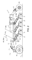
- FIG. 2 is a side view of the embodiment of FIG. 1 where the front and rear ends of the implement frame are the same distance above the ground;
- FIG. 3 is a side view of the embodiment of FIG. 1 where the front end of the implement frame is higher than the rear end thereof;
- FIG. 4 is a side view of the embodiment of FIG. 1 where the front end of the implement frame is lower than the rear end thereof;
- FIG. 5 is a schematic top view of an alternate embodiment of the seeding apparatus of the present disclosure.
- FIG. 6 is a schematic side view of a furrow opener assembly of the embodiment of FIG. 5 shown in a first position forming a furrow with a first depth;
- FIG. 7 is a schematic side view of a furrow opener assembly of the embodiment of FIG. 5 shown in a second position forming a furrow with a second depth greater than the first depth;
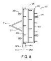
- FIG. 8 is a schematic top view of a further alternate embodiment of the seeding apparatus of the present disclosure.
- FIG. 9 is a schematic side view of a furrow opener assembly of the embodiment of FIG. 8 shown in a first position forming a furrow with a first depth;
- FIG. 10 is a schematic side view of a furrow opener assembly of the embodiment of FIG. 8 shown in a second position forming a furrow with a second depth greater than the first depth;
- FIG. 11 is a schematic side view of an alternate furrow opener assembly for use with the embodiment of FIG. 8 shown in a first position forming a furrow;
- FIG. 12 is a schematic side view of the alternate furrow opener assembly of FIG. 11 shown with the furrow opener above the ground and the hydraulic cylinder moving the furrow opener assembly toward the raised position;
- FIG. 13 is a schematic side view of a further alternate furrow opener assembly for use with the embodiment of FIG. 8 shown in a first position forming a furrow with a first depth;
- FIG. 14 is a schematic side view of the furrow opener assembly of FIG. 13 shown in a second position forming a furrow with a second depth less than the first depth.
- FIGS. 1-4 schematically illustrate an embodiment of a seeding apparatus 1 of the present disclosure comprising an implement frame 3 mounted on wheels 5 for travel over the ground 7 in an operating travel direction T.
- a plurality of furrow opener assemblies 9 is mounted on the implement frame 3 .
- Each furrow opener assembly 9 extends rearward from a lateral frame member 11 of the implement frame 3 and comprises a front link member 13 fixed to the lateral frame member 11 , and upper and lower parallel arm members 15 A, 15 B are pivotally attached at front ends thereof to the front link member 13 about corresponding upper and lower front pivot axes UFA, LFA oriented substantially horizontally and perpendicular to the operating travel direction T, and pivotally attached at rear ends thereof to a rear link member 17 about corresponding upper and lower rear pivot axes URA, LRA oriented substantially parallel to the front pivot axes UFA, ULA.
- a furrow opener bracket 19 is attached to the rear link member 17 , and a furrow opener 21 is attached to a lower portion of the furrow opener bracket 19 .
- the furrow opener 21 is operative to form a furrow 23 when a bottom end thereof is engaged in the ground 7 .
- a packer wheel arm 25 is attached to the rear link 17 and a packer wheel 27 is rotatably attached to a rear end of the packer wheel arm 25 .
- the vertical position of the packer wheel 27 with respect to the furrow opener 21 may be adjustable to provide a wider range of furrow depth however during a seeding operation the furrow opener 21 and the packer wheel 27 are in fixed positions with respect to the rear link member 17 .
- the furrow openers schematically illustrated in this disclosure are, for simplicity of illustration, shown as knife or hoe type openers however it will be recognized that a disc opener could also be rotatably mounted to the lower portion of the furrow opener brackets illustrated herein.
- the furrow openers assembly 9 includes a parallel arm assembly with the front link 13 fixed to the implement frame 3 and the furrow opener 21 and packer wheel 27 both fixed to the rear link 17 .
- this furrow opener assembly 9 can pivot up and down with respect to the implement frame 3 and the depth of the furrow 23 created by the furrow opener 21 will remain constant.
- a bias element typically a hydraulic cylinder 29 as illustrated, is operative to exert a downward bias force DBF on the furrow opener assembly 9 .
- the hydraulic cylinder 29 typically also provides the raising mechanism operative to move the furrow opener assemblies 9 between a lowered operating position 9 A and a raised transport position 9 B as schematically illustrated in FIG. 4 .
- a front pivot line FPL connecting the upper and lower front pivot axes UFA, LFA is substantially parallel to a rear pivot line RPL connecting the upper and lower rear pivot axes URA, LRA, and the front and rear pivot lines FPL, RPL are oriented at a pivot angle PN with respect to a vertical orientation V, and the pivot angle PN is adjustable to vary a furrow depth of the furrow 23 .
- the pivot angle is adjusted by selectively tilting a front end 3 F of the implement frame 3 up or down with respect to a rear end 3 R of the implement frame 3 to adjust the pivot angle PN.
- the implement frame 3 is mounted on front wheels 5 F and rear wheels 5 R, and the front wheels 5 F and the rear wheels 5 R are moved selectively up or down with respect to the implement frame 3 to tilt the front end 3 F of the implement frame 3 up or down with respect to the rear end 3 R of the implement frame 3 .
- FIGS. 2-4 schematically illustrate this tilting of the implement frame 3 and the resulting change in the pivot angle PN.
- the line representing the ground 7 is placed at a fixed location with respect to the implement wheels 5 and the packer wheels 27 to illustrate the changes in the vertical position of the bottom of the furrow openers 21 with respect to the ground 7 , and with respect to the implement wheels 5 and the packer wheels 27 which follow the ground.
- the implement frame 3 is oriented substantially level with all lateral frame members 11 the same distance above the ground surface 7 , and the front pivot line FPL oriented at a first pivot angle PNA.
- the bottom ends of the furrow openers 21 are on the line 7 representing the ground surface.
- FIG. 3 the front wheels 5 F are moved downward and the rear wheels 5 R are moved upward with respect to the implement frame 3 by wheel actuators 31 to tilt the front end 3 F of the implement frame 3 up with respect to the rear end 3 R thereof compared to the level orientation of FIG. 2 . Tilting the front end 3 F of the implement frame 3 up with respect to the rear end 3 R thereof moves the upper front pivot axis UFA rearward with respect to the lower front pivot axis LFA and the front pivot line FPL is oriented at a second pivot angle PNB that is greater than the first pivot angle PNA.
- the bottom ends of the furrow openers 21 are slightly above the line 7 representing the ground surface, indicating the furrow openers 21 have been raised with respect to the ground surface 7 and with respect to the implement wheels 5 and the packer wheels 27 which follow the ground, and thus the depth of the furrow 23 is decreased.
- FIG. 4 the front wheels 5 F are moved upward and the rear wheels 5 R are moved downward with respect to the implement frame 3 by wheel actuators 31 to tilt the front end 3 F of the implement frame 3 down with respect to the rear end 3 R thereof compared to the level orientation of FIG. 2 .
- Tilting the front end 3 F of the implement frame 3 down with respect to the rear end 3 R thereof moves the upper front pivot axis UFA forward with respect to the lower front pivot axis LFA and the front pivot line FPL is oriented at a third pivot angle PNC that is less than the first pivot angle PNA.
- the bottom ends of the furrow openers 21 are slightly below the line 7 representing the ground surface, indicating the furrow openers 21 have been lowered with respect to the ground surface 7 and with respect to the implement wheels 5 and the packer wheels 27 which follow the ground, and thus the depth of the furrow 23 is increased.
- both the front and rear wheels 5 F, 5 R are moved up and down however it is contemplated that tilting of the implement frame 3 could be accomplished by moving only the front wheels 5 F or only the rear wheels 5 R.
- a desired furrow depth change might be only 0.5 inches or less and it can be seen that tilting the implement frame 3 only slightly may accomplish the desired change.
- FIGS. 5-7 schematically illustrate an alternate apparatus 101 of the present disclosure comprising an implement frame 103 mounted on wheels 105 for travel over the ground 107 in an operating travel direction T.
- front and rear wheels 105 F, 105 R support the implement frame 103 at a constant height above the ground surface 107 .
- Furrow opener assemblies 109 are mounted on the implement frame 103 and each furrow opener assembly 109 extends rearward from a lateral frame member 111 of the implement frame 103 and comprises a front link member 113 fixed to the lateral frame member 111 , and upper and lower parallel arm members 115 A, 115 B are pivotally attached at front ends thereof to the front link member 113 about corresponding upper and lower front pivot axes UFA, LFA oriented substantially horizontally and perpendicular to the operating travel direction T, and pivotally attached at rear ends thereof to a rear link member 117 about corresponding upper and lower rear pivot axes URA, LRA oriented substantially parallel to the front pivot axes UFA, ULA.
- a furrow opener bracket 119 is attached to the rear link member 117 , and a furrow opener 121 is attached to a lower portion of the furrow opener bracket 119 .
- the furrow opener 121 is operative to form a furrow 123 when a bottom end thereof is engaged in the ground 107 .
- a packer wheel arm 125 is attached to the rear link 117 and a packer wheel 127 is rotatably attached to a rear end of the packer wheel arm 125 .
- the relative position of the packer wheel 127 and furrow opener 121 may be adjustable to provide a wider range of furrow depth however during a seeding operation the furrow opener 121 and the packer wheel 127 are in fixed positions with respect to the rear link member 117 .
- the lateral frame members 111 are rotatably mounted to the implement frame 103 about a lateral rotation axis LR oriented substantially parallel to the pivot axes UFA, LFA, URA, LRA and the pivot angle PN is adjusted by rotating the lateral frame member 111 and the front link member 113 attached thereto.
- a lock mechanism 133 is operative to secure the lateral frame member 111 at a selected rotational position.
- the lateral rotation axis LR passes through the front pivot line FPL at a mid-point between the upper and lower frame pivot axes UFA, LFA.
- FIG. 6 shows the lateral frame member 111 oriented so the front pivot line is oriented at a first pivot angle PNA and the furrow opener 121 forms a furrow 123
- FIG. 7 shows the lateral frame member 111 oriented so the front pivot line is oriented at a second pivot angle PNB and the furrow opener 121 forms a deeper furrow 123 ′.
- the first pivot angle PNA is only three degrees greater than the second pivot angle PNB and results in a furrow depth increase of almost one inch.
- FIGS. 6 and 7 also illustrate how the fore and aft presentation angle FN of the furrow opener 121 with respect to the ground surface 107 changes as the pivot angle PN changes.
- a change in the pivot angle PN causes an equal change in the presentation angle FN.
- the pivot angle PN decreases by about three degrees from the pivot angle PNA of FIG. 6 to the pivot angle PNA of FIG. 5 and the presentation angle FN correspondingly increases by about three degrees from the presentation angle FNA shown in FIG. 6 to the presentation angle FNB shown in FIG. 7 .
- the angular relationship between the furrow opener 121 and the ground surface 107 dictates the form of the furrow 123 made, and the relationship between the furrow opener 121 and a product tube delivering agricultural products to the furrow 123 dictates the location of the agricultural product in the furrow 123 .
- the furrow opener 121 must be designed to operate satisfactorily within a contemplated range of presentation angles FN that the opener will encounter during use.
- a desired range of furrow depths might be about two inches, for example between one half inch to two and one half inches.
- the illustrated seeding apparatus 101 could then provide satisfactory operation for furrow openers 121 with a range of presentation angle that is plus or minus three degrees.
- the present disclosure also provides further embodiments described below where the presentation angle is kept constant as the furrow depth is changed.
- FIGS. 8-10 schematically illustrate an alternate apparatus 201 of the present disclosure comprising an implement frame 203 mounted on wheels 205 for travel over the ground 207 in an operating travel direction T.
- the wheels 205 support the implement frame 203 at a constant height above the ground surface 207 .
- a rockshaft 235 is rotatably attached to a lateral frame member 211 of the implement frame 203 about a lateral rotation axis LR, and a lock mechanism 233 is operative to secure the rockshaft 235 at a selected rotational position.
- a plurality of furrow opener assemblies 209 are attached to the implement frame 203 .
- Each furrow opener assembly 209 extends rearward from the lateral frame member 211 and the rockshaft 235 and each furrow opener assembly 209 comprises two separate parallel arm assemblies.
- a frame parallel arm assembly FPAA comprises a front frame link member 213 F fixed to the lateral frame member 211 .
- the front frame link member 213 F is provided by the link bracket 237 extending down from the lateral frame member 211 and the rockshaft bracket 239 mounting the rockshaft 235 to the lateral frame member 211 .
- the link bracket 237 and rockshaft 235 are thus in fixed positions with respect to each other, and the link bracket 237 defines the lower front frame pivot axis LFMA and the lateral rotation axis LR provides the upper front frame pivot axis UFMA.
- a rear frame link member 217 F defines upper and lower rear frame pivot axes URMA, LRMA, wherein the frame pivot axes are arranged so that a front frame pivot line FFPL between the upper and lower front frame pivot axes UFMA, LFMA and a rear frame pivot line RFPL between the upper and lower rear frame pivot axes URMA, LRMA, are parallel and of equal length.
- a rockshaft parallel arm assembly RPAA comprises a front rockshaft link member 213 R fixed to the rockshaft 235 and defining upper and lower front rockshaft pivot axes UFSA, LFSA and a rear rockshaft link member 217 R defining upper and lower rear rockshaft pivot axes URSA, LRSA, wherein the rockshaft pivot axes are arranged so that a front rockshaft pivot line FRPL between the upper and lower front rockshaft pivot axes UFSA, LFSA and a rear rockshaft pivot line RRPL between the upper and lower rear rockshaft pivot axes URSA, LRSA are parallel and of equal length.
- a furrow opener bracket 219 is fixed to the rear frame link member 217 F which is pivotally attached to the rear rockshaft link member 217 R about the upper rear frame axis URMA A.
- furrow opener 221 is attached to a lower portion of the furrow opener bracket 219 and is operative to form a furrow 223 when a bottom end thereof is engaged in the ground 207 .
- a packer wheel arm 225 is attached to the rear rockshaft link member 217 R and pivotally attached to the rear frame link member 217 F about the upper rear frame axis URMA.
- a packer wheel 227 is rotatably attached to a rear end of the packer wheel arm 225 .
- a bias element illustrated as a hydraulic cylinder 229 , is operative to exert a downward bias force DBF on the furrow opener assembly 209 , and a raising mechanism, here provided by the same hydraulic cylinder 229 , is operative to move the furrow opener assembly 209 between the illustrated lowered operating position and a raised transport position indicated by the raised packer wheel 227 R.
- the furrow depth of the furrow 223 is adjusted from a first depth shown in FIG. 9 to a second depth shown in FIG. 10 by rotating the rockshaft 235 from a first rotational position to a second rotational position, and the illustrated frame and rockshaft parallel arm assemblies maintain the fore and aft presentation angle FN of the furrow opener at a constant angle.
- the furrow opener bracket 219 is fixed to the rear frame link member 217 F and the packer wheel arm 225 is fixed to the rear rockshaft link member 217 R, and the rear frame link member 217 F is pivotally attached to the rear rockshaft link member 217 R about the upper rear frame pivot axis URMA.
- the front rockshaft link member 213 R is fixed to the rockshaft 235 such that the lateral rotation axis LR is located on the front rockshaft pivot line FRPL between the upper and lower front rockshaft pivot axes UFSA, LFSA.
- the upper frame front pivot axis UFMA coincides with the lateral rotation axis LR
- the rear frame link member 217 F is pivotally attached to the rear rockshaft link member 217 R about the upper rear frame pivot axis URMA at a location on the rear rockshaft pivot line RRPL between the upper and lower rear rockshaft pivot axes URSA, LRSA corresponding to the location of the lateral rotation axis such that a virtual upper frame arm 215 AF is formed between the upper frame front pivot axis UFMA and the upper frame rear pivot axis URMA that is parallel to the lower frame arm 215 BF.
- the rockshaft parallel arm assembly RPAA comprises equal length upper and lower rockshaft arms 215 AR, 215 BR pivotally attached at front and rear ends thereof to the front and rear rockshaft link members 213 R, 217 R about the corresponding upper and lower front and rear rockshaft pivot axes UFSA, LFSA, URSA, LRSA.
- the frame parallel arm assembly FPAA comprises the virtual upper frame arm 215 AF and a lower frame arm 215 BF pivotally attached at front and rear ends thereof to the front and rear frame link members 213 F, 217 F about the corresponding lower front and rear frame pivot axes LFMA, LRMA under the lower rockshaft arm 215 BR.
- the furrow depth is increased by rotating the rockshaft 235 such that the upper front rockshaft pivot axis UFSA is moved forward with respect to the lower front rockshaft pivot axis LFSA, decreasing the pivot angle PN between the front rockshaft pivot line FRPL and the vertical orientation V from the pivot angle PNA shown in FIG. 9 to the lesser angle PNB shown in FIG. 10 . Again a three degree difference results in a furrow depth increase of almost an inch.
- the furrow depth is decreased by rotating the rock shaft 235 such that the upper front rockshaft pivot axis UFSA is moved rearward with respect to the lower front rockshaft pivot axis LFSA, increasing the pivot angle PN.
- the use of two parallel arm assemblies allows one, in this case the rockshaft parallel arm assembly RPAA, to maintain the vertical position of the furrow opener 221 with respect to the packer wheel 227 constant while the other, in this case the frame parallel arm assembly FPAA to maintain the presentation angle FN constant as rockshaft 235 is rotated to change the depth of the furrow 223 .
- FIGS. 11 and 12 schematically illustrate a variation 209 ′ of the furrow opener assembly 209 shown in FIGS. 8-10 .
- a bracket stop 241 is fixed to the rear frame link member 217 F and the furrow opener bracket 219 ′ is pivotally attached to the rear rockshaft link member 217 R about opener pivot axis OPA and is connected during operation to the rear frame link member 217 F by bearing against the bracket stop 241 .
- the furrow opener bracket 219 ′ extends upward to a top end 243 thereof above the rear rockshaft link member 217 R, and the bias element, illustrated as hydraulic cylinder 229 ′, exerts a rearward bias force RBF on the top end 243 of the furrow opener bracket 219 ′ to force the furrow opener bracket 219 ′ against the bracket stop 241 and to exert the downward bias force DBF on the top end 243 of the furrow opener bracket 219 ′.
- the bias element illustrated as hydraulic cylinder 229 ′
- Pressurized hydraulic fluid is directed into a first end 229 A of the hydraulic cylinder 229 ′ to exert the downward bias force DBF and pressurized hydraulic fluid is directed into an opposite second end 229 B of the hydraulic cylinder 229 ′ such that the hydraulic cylinder 229 ′ exerts a forward force FF on the top end 243 of the furrow opener bracket 219 ′ which pivots the furrow opener bracket 219 ′ about the opener pivot axis OPA to the position of FIG. 12 where a raising block 245 contacts the packer wheel arm 225 and further forward movement of the top end 243 of the furrow opener bracket 219 ′ raises the furrow opener assembly 209 ′ to the raised transport position indicated by the packer wheel 227 R. Furrow depth adjustments are made in the same fashion as with the furrow opener assembly 209 by rotating the rockshaft 235 .
- FIG. 12 also shows a tripped position for the furrow opener bracket 219 ′ such as would occur when the furrow opener encounters an obstruction such as a rock that forces the furrow opener bracket 219 ′ rearward overcoming the bias force RBF exerted by the hydraulic cylinder 229 ′.
- an obstruction such as a rock that forces the furrow opener bracket 219 ′ rearward overcoming the bias force RBF exerted by the hydraulic cylinder 229 ′.
- various trip mechanisms as are known in the art will typically be incorporated in the furrow opener assemblies to allow the furrow opener to move out of the illustrated operating positions to a tripped position.
- FIGS. 13 and 14 schematically illustrate a further alternate furrow opener assembly 309 comprising frame and rockshaft parallel arm assemblies where the furrow opener bracket 319 is fixed to the rear frame link member 317 F and the packer wheel arm 325 is pivotally attached to the rear frame link member 317 F and is pivotally attached to the rear rockshaft link member 317 R.
- the furrow opener assembly 309 like the furrow openers 209 , 209 ′ described above, also maintains a constant presentation angle FN for the furrow opener 321 while allowing the furrow depth to be changed by rotating the rockshaft 335 .
- the rockshaft 335 is above the frame parallel arm assembly FPAA.
- the front rockshaft link member 313 R of the rockshaft parallel arm assembly RPAA is fixed to the rockshaft 335 such that the lateral rotation LR axis coincides with the lower front rockshaft pivot axis LFSA.
- the rear frame link member 317 F of the frame parallel arm assembly FPAA extends above the upper parallel arm member 315 AF of the frame parallel arm assembly FPAA and is pivotally attached to the rear rockshaft link member 317 R about the lower rear rockshaft pivot axis LRSA.
- the packer wheel arm 325 comprises an upper packer arm 325 A pivotally attached at a front end thereof to the rear rockshaft link member 317 R about the upper rear rockshaft pivot axis URSA and a lower packer arm 325 B pivotally attached to the rear frame link member 317 F about the lower rear frame pivot axis LRMA.
- the upper and lower packer arms 325 A, 325 B are attached at rear portions thereof to each other and rotatably attached to the packer wheel 327 .
- the frame parallel arm assembly FPAA comprises equal length upper and lower frame arms 315 AF, 315 BF pivotally attached at front and rear ends thereof to the front and rear frame link members 313 F, 317 F about the corresponding upper and lower front and rear frame pivot axes UFMA, LFMA, URMA, LRMA.
- the rockshaft parallel arm assembly RPAA comprises an upper rockshaft arm 315 AR pivotally attached at front and rear ends thereof to the front and rear rockshaft link members 313 R, 317 R about the corresponding upper front and rear rockshaft pivot axes UFSA, URSA, and a virtual lower rockshaft arm 315 BR that is formed between the front lower rockshaft pivot axis LFSA and the lower rockshaft rear pivot axis LRSA.
- the rear frame link member 317 F of the frame parallel arm assembly FPAA maintains the furrow opener bracket 319 attached thereto, and thus the furrow opener 321 , at a constant presentation angle FN with respect to the ground 307 .
- the rear frame link member 317 F is also attached to the rear rockshaft link member 317 R and so maintains the packer wheel 327 and furrow opener 321 at a constant vertical relationship, which can be changed by rotating the rockshaft 335 to change the pivot angle PN between the front rockshaft pivot line FRPL and the vertical orientation V.
- the present disclosure further provides a method of forming a furrow 23 in a ground surface 7 .
- the method comprises connecting a front link member 13 of a parallel arm assembly to a lateral frame member 11 of an implement frame 3 mounted on wheels 5 for travel over the ground surface 7 in an operating travel direction such that the parallel arm assembly extends rearward from the lateral frame member 11 ; wherein a front pivot line FPL connects upper and lower front pivot axes UFA, LFA of the parallel arm assembly and is substantially parallel to a rear pivot line RPL connecting upper and lower rear pivot axes URA, LRA of the parallel arm assembly, and the front and rear pivot lines FPL, RPL are oriented at a pivot angle PN with respect to a vertical orientation V; connecting a furrow opener bracket 19 to a rear link member 17 of the parallel arm assembly, and attaching a furrow opener 21 to a lower portion of the furrow opener bracket 19 , wherein the furrow opener 21 is operative to form the furrow 23 when a bottom end thereof is engaged in the ground surface
- the method comprises rigidly attaching the front link member 13 to the lateral frame member 11 , and attaching the furrow opener bracket 19 and the packer wheel 27 to the rear link member 17 such that during operation the rear link member 17 , the furrow opener 21 , and the packer wheel 27 are in fixed positions with respect to each other.
- the upper front pivot axis UFA moves rearward with respect to the lower front pivot axis LFA when the pivot angle PN changes from the first pivot angle PNA to the second pivot angle PNB, and the first furrow depth is greater than the second furrow depth.
- the upper front pivot axis UFA moves forward with respect to the lower front pivot axis LFA when the pivot angle PN changes from the second pivot angle PNB to the third pivot angle PNC, and wherein the second furrow depth is less than the third furrow depth.
- the method can comprise changing the pivot angle PN by raising and lowering a front end 3 F of the implement frame 3 with respect to a rear end 3 r of the implement frame 3 as schematically illustrated in FIGS. 2-4 .
- the method can comprise rotatably mounting the lateral frame member 111 to the implement frame 103 about a lateral rotation axis LR oriented substantially parallel to the front and rear pivot axes UFA, LFA, URA, LRA and changing the pivot angle PN by rotating the lateral frame member 111 about the lateral rotation axis LR as schematically illustrated in FIGS. 6 and 7 .
- the method of forming a furrow in a ground surface 207 can further comprise rotatably mounting a rockshaft 235 to the implement frame 203 about a lateral rotation axis LR as schematically illustrated in the furrow opener assembly 209 of FIGS. 9 and 10 comprising a frame parallel arm assembly FPAA and a rockshaft parallel arm assembly RPAA.
- the furrow opener bracket 219 is pivotally attached to the rear rockshaft link member 217 R and connected during operation to the rear frame link member 271 F.
- a packer wheel arm 225 is connected to the rear frame link member 217 F and the rear rockshaft link member 217 R and the packer wheel 227 is rotatably attached to a rear end of the packer wheel arm 225 .
- Exerting the downward bias force DBF on the parallel arm assembly causes the furrow opener 221 to engage the ground surface 207 as the implement frame 203 moves across the ground surface 207 , and orienting the pivot angle PN at a first pivot angle PNA forms the furrow 223 with a first furrow depth, and orienting the pivot angle PN at a second pivot angle PNB forms the furrow 223 with a second furrow depth different from the first furrow depth.
- the method includes configuring the furrow opener assembly 209 to maintain a fore and aft presentation angle FN of the furrow opener 221 with respect to the ground at a constant angle as the rockshaft pivot angle PN changes.
- the method comprises fixing the packer wheel arm 225 to the rear rockshaft link member 217 R, and pivotally attaching the rear frame link member 217 F to the rear rockshaft link member 217 R; fixing the front rockshaft link member 213 R to the rockshaft 235 such that the lateral rotation axis LR is located on the front rockshaft pivot line FRPL midway between the upper and lower front rockshaft pivot axes UFSA, LFSA; configuring the front frame link member 213 F such that the upper frame front pivot axis UFMA coincides with the lateral rotation axis LR; and pivotally attaching the rear frame link member 217 F to the rear rockshaft link member 217 R about the upper rear frame pivot axis URMA at a location on the rear rockshaft pivot line RRPL midway between the upper and lower rear rockshaft pivot axes URSA, LRSA such that a virtual upper frame arm 215 AF is formed between the upper frame front pivot axis UFMA and the upper frame rear pivot axi
- the method can also comprise fixing a bracket stop 241 to the rear frame link member 217 F and pivotally attaching the furrow opener bracket 219 ′ to the rear rockshaft link member 217 R and during operation connecting the furrow opener bracket 219 ′ to the rear frame link member 217 F by forcing the furrow opener bracket 219 ′ against the bracket stop 241 ; and during operation fixing the packer wheel 227 in a fixed position with respect to the rear rockshaft link member 217 R.
- the furrow opener bracket 219 ′ extends upward to a top end 243 thereof above the rear rockshaft link member 217 R, and a hydraulic cylinder 229 ′ exerts a bias force RBF rearward and downward on the top end 243 of the furrow opener bracket 219 ′ to force the furrow opener bracket 219 ′ against the bracket stop 241 and to exert the downward bias force DBF on the top end 243 of the furrow opener bracket 219 ′.
- Pressurized hydraulic fluid is directed into a first end 229 A of the hydraulic cylinder 229 ′ to exert the downward bias force DBF and pressurized hydraulic fluid is directed into an opposite second end 229 B of the hydraulic cylinder 229 ′ to move the furrow opener assembly 209 ′ to the raised transport position.
- FIGS. 13 and 14 schematically illustrate a further method of forming a furrow in a ground surface by rotatably mounting a rockshaft 335 to the implement frame about a lateral rotation axis LR and using both a frame parallel arm assembly FPAA and a rockshaft parallel arm assembly RPAA.
- the method comprises pivotally attaching the packer wheel arm 325 to the rear frame link member 317 F and to the rear rockshaft link member 317 R; positioning the rockshaft 335 above the frame parallel arm assembly; fixing the front rockshaft link member 313 R to the rockshaft 335 such that the lateral rotation axis LR coincides with the lower front rockshaft pivot axis LFSA; extending the rear frame link member 317 F above the frame parallel arm assembly FPAA and pivotally attaching a top end 343 thereof to the rear rockshaft link member 317 R about the lower rear rockshaft pivot axis LRSA; and configuring the packer wheel arm 325 to comprise an upper packer arm 325 A pivotally attached at a front end thereof to the rockshaft link member 317 R about the upper rear rockshaft pivot axis URSA and a lower packer arm 325 B pivotally attached about the lower rear frame pivot axis LRMA to the rear frame link member 317 F, and wherein the upper and lower packer arms 325 A, 325 B are attached at rear portions thereof to
- the present disclosure provides a seeding apparatus with trailing arm furrow opener assemblies where the depth of the furrow formed by the furrow openers can be quickly changed to suit different crops and soil conditions.
- the depth of penetration of all the furrow openers on a seeding implement can be adjusted at the same time.
- the presentation angle of the furrow opener with respect to the ground surface can be maintained at a constant desired angle.
Landscapes
- Life Sciences & Earth Sciences (AREA)
- Soil Sciences (AREA)
- Environmental Sciences (AREA)
- Engineering & Computer Science (AREA)
- Mechanical Engineering (AREA)
- Zoology (AREA)
- Soil Working Implements (AREA)
- Agricultural Machines (AREA)
- Sowing (AREA)
Applications Claiming Priority (2)
| Application Number | Priority Date | Filing Date | Title |
|---|---|---|---|
| CA2968181A CA2968181C (fr) | 2017-05-24 | 2017-05-24 | Ajustement de profondeur rapide d'ouvre-bras paralleles |
| CA2968181 | 2017-05-24 |
Publications (2)
| Publication Number | Publication Date |
|---|---|
| US20180338412A1 US20180338412A1 (en) | 2018-11-29 |
| US10405486B2 true US10405486B2 (en) | 2019-09-10 |
Family
ID=64400099
Family Applications (2)
| Application Number | Title | Priority Date | Filing Date |
|---|---|---|---|
| US15/706,843 Active 2037-10-01 US10405486B2 (en) | 2017-05-24 | 2017-09-18 | Quick depth adjustment for parallel arm openers |
| US15/706,836 Active 2037-11-10 US10251334B2 (en) | 2017-05-24 | 2017-09-18 | Quick depth adjustment for parallel arm openers |
Family Applications After (1)
| Application Number | Title | Priority Date | Filing Date |
|---|---|---|---|
| US15/706,836 Active 2037-11-10 US10251334B2 (en) | 2017-05-24 | 2017-09-18 | Quick depth adjustment for parallel arm openers |
Country Status (3)
| Country | Link |
|---|---|
| US (2) | US10405486B2 (fr) |
| AU (2) | AU2017235926B2 (fr) |
| CA (1) | CA2968181C (fr) |
Families Citing this family (8)
| Publication number | Priority date | Publication date | Assignee | Title |
|---|---|---|---|---|
| CA2968181C (fr) * | 2017-05-24 | 2019-02-26 | Bourgault Industries Ltd. | Ajustement de profondeur rapide d'ouvre-bras paralleles |
| SE543389C2 (sv) * | 2018-11-30 | 2020-12-29 | Vaederstad Holding Ab | Radenhet för lantbruksredskap, lantbruksredskap omfattande sådan radenhet samt förfarande för inställning av sådjup |
| CN109819722B (zh) * | 2019-01-29 | 2021-08-31 | 吉林大学 | 一种入土角可调的双行自锁式开沟器 |
| US11006571B2 (en) * | 2019-05-09 | 2021-05-18 | Cnh Industrial America Llc | Floatation springs attached to adjustable skid shoes |
| US11277955B2 (en) * | 2019-10-08 | 2022-03-22 | Cnh Industrial Canada, Ltd. | System and method for adjusting the alignment of ground engaging tools of an agricultural implement |
| CN110999581A (zh) * | 2019-12-26 | 2020-04-14 | 洛阳智能农业装备研究院有限公司 | 一种拖拉机提升系统控制装置及方法 |
| CA3089917A1 (fr) * | 2020-08-11 | 2022-02-11 | Bourgault Industries Ltd. | Appareil pour ajuster la profondeur de graine et d'engrais |
| CA3089919A1 (fr) | 2020-08-11 | 2022-02-11 | Bourgault Industries Ltd. | Optimisation du placement relatif des graines et des engrais |
Citations (15)
| Publication number | Priority date | Publication date | Assignee | Title |
|---|---|---|---|---|
| US3517747A (en) | 1967-08-21 | 1970-06-30 | Int Harvester Co | Automatic control means for implement |
| US5234060A (en) * | 1992-02-21 | 1993-08-10 | The United States Of America As Represnted By The Secretary Of Agriculture | Pressure and depth control in agricultural implement |
| US5396851A (en) | 1993-03-08 | 1995-03-14 | Beaujot; Norbert F. | Dual material dispensing assembly |
| US5398771A (en) | 1993-02-23 | 1995-03-21 | Crustbuster/Speed King, Inc. | Grain Drill |
| US5609114A (en) | 1994-04-15 | 1997-03-11 | Barton; Hugh | No-till disk opening system and method |
| US7159523B2 (en) | 2005-01-24 | 2007-01-09 | Bourgault Industries Ltd. | Method and apparatus of agricultural field seeding |
| US7261048B1 (en) * | 2005-11-30 | 2007-08-28 | Bourgault Industries Ltd. | Parallel link trailing arm for seeders |
| US7549481B2 (en) | 2007-06-12 | 2009-06-23 | Bourgault Industries Ltd. | Parallel link mounting arm for a furrow opener |
| US7674997B2 (en) * | 2006-10-17 | 2010-03-09 | Johns Manville | Spinner for fiberizing glass and method |
| US20110282556A1 (en) | 2010-05-14 | 2011-11-17 | Bourgault Industries Ltd. | Depth Adjustment of Trailing Arm Furrow Openers |
| US8220559B2 (en) * | 2007-07-10 | 2012-07-17 | Ausplow Pty. Ltd. | Plough assembly for deep soil cultivation |
| EP2712492A2 (fr) * | 2012-09-27 | 2014-04-02 | Lars Askling | Support d'outil pour bill de semis et outils pour travailler le sol |
| US8733466B2 (en) * | 2009-05-27 | 2014-05-27 | Cnh Industrial Canada, Ltd. | Adjustable packer wheel seeding system and method |
| US9706704B2 (en) * | 2013-09-13 | 2017-07-18 | Ausplow Pty. Ltd. | Plough assembly |
| US20180338411A1 (en) * | 2017-05-24 | 2018-11-29 | Bourgault Industries Ltd. | Quick depth adjustment for parallel arm openers |
Family Cites Families (1)
| Publication number | Priority date | Publication date | Assignee | Title |
|---|---|---|---|---|
| US8342258B2 (en) * | 2010-01-26 | 2013-01-01 | Cnh Canada, Ltd. | Seeding implement depth adjustment mechanism |
-
2017
- 2017-05-24 CA CA2968181A patent/CA2968181C/fr active Active
- 2017-09-18 US US15/706,843 patent/US10405486B2/en active Active
- 2017-09-18 US US15/706,836 patent/US10251334B2/en active Active
- 2017-09-27 AU AU2017235926A patent/AU2017235926B2/en active Active
-
2019
- 2019-05-29 AU AU2019203760A patent/AU2019203760B2/en active Active
Patent Citations (15)
| Publication number | Priority date | Publication date | Assignee | Title |
|---|---|---|---|---|
| US3517747A (en) | 1967-08-21 | 1970-06-30 | Int Harvester Co | Automatic control means for implement |
| US5234060A (en) * | 1992-02-21 | 1993-08-10 | The United States Of America As Represnted By The Secretary Of Agriculture | Pressure and depth control in agricultural implement |
| US5398771A (en) | 1993-02-23 | 1995-03-21 | Crustbuster/Speed King, Inc. | Grain Drill |
| US5396851A (en) | 1993-03-08 | 1995-03-14 | Beaujot; Norbert F. | Dual material dispensing assembly |
| US5609114A (en) | 1994-04-15 | 1997-03-11 | Barton; Hugh | No-till disk opening system and method |
| US7159523B2 (en) | 2005-01-24 | 2007-01-09 | Bourgault Industries Ltd. | Method and apparatus of agricultural field seeding |
| US7261048B1 (en) * | 2005-11-30 | 2007-08-28 | Bourgault Industries Ltd. | Parallel link trailing arm for seeders |
| US7674997B2 (en) * | 2006-10-17 | 2010-03-09 | Johns Manville | Spinner for fiberizing glass and method |
| US7549481B2 (en) | 2007-06-12 | 2009-06-23 | Bourgault Industries Ltd. | Parallel link mounting arm for a furrow opener |
| US8220559B2 (en) * | 2007-07-10 | 2012-07-17 | Ausplow Pty. Ltd. | Plough assembly for deep soil cultivation |
| US8733466B2 (en) * | 2009-05-27 | 2014-05-27 | Cnh Industrial Canada, Ltd. | Adjustable packer wheel seeding system and method |
| US20110282556A1 (en) | 2010-05-14 | 2011-11-17 | Bourgault Industries Ltd. | Depth Adjustment of Trailing Arm Furrow Openers |
| EP2712492A2 (fr) * | 2012-09-27 | 2014-04-02 | Lars Askling | Support d'outil pour bill de semis et outils pour travailler le sol |
| US9706704B2 (en) * | 2013-09-13 | 2017-07-18 | Ausplow Pty. Ltd. | Plough assembly |
| US20180338411A1 (en) * | 2017-05-24 | 2018-11-29 | Bourgault Industries Ltd. | Quick depth adjustment for parallel arm openers |
Non-Patent Citations (1)
| Title |
|---|
| Australian Office Action, Examination report No. 1 for standard patent application, dated Dec. 7, 2018 for Application No. AU 2017235926, 8 pgs. |
Also Published As
| Publication number | Publication date |
|---|---|
| CA2968181A1 (fr) | 2018-11-24 |
| AU2019203760A1 (en) | 2019-06-20 |
| US10251334B2 (en) | 2019-04-09 |
| AU2019203760B2 (en) | 2021-01-28 |
| US20180338411A1 (en) | 2018-11-29 |
| AU2017235926B2 (en) | 2019-05-02 |
| AU2017235926A1 (en) | 2018-12-13 |
| CA2968181C (fr) | 2019-02-26 |
| US20180338412A1 (en) | 2018-11-29 |
Similar Documents
| Publication | Publication Date | Title |
|---|---|---|
| US10405486B2 (en) | Quick depth adjustment for parallel arm openers | |
| US7549481B2 (en) | Parallel link mounting arm for a furrow opener | |
| US7159523B2 (en) | Method and apparatus of agricultural field seeding | |
| US7412933B2 (en) | Seeder with trailing arm and hoe-type mid row bander | |
| US7261048B1 (en) | Parallel link trailing arm for seeders | |
| EP2503869B1 (fr) | Ensemble de réglage de pression descendante pour semoir à disque d'outil agricole | |
| US8006775B2 (en) | Strip tillage implement | |
| CA2899900C (fr) | Dispositif de fermeture pour un accessoire agricole | |
| CN100586397C (zh) | 触地设备 | |
| US20090158981A1 (en) | Single Disc Furrow Opener with Walking Beam | |
| US20210059102A1 (en) | Planter Row Unit And Associated Systems And Methods | |
| EP4179857B1 (fr) | Unité de rangée | |
| US7640874B2 (en) | Seeding implement with front rockshaft-mounted fertilizer openers | |
| US12082518B2 (en) | Location-based control system for an agricultural implement | |
| EP4346367B1 (fr) | Semoir pour cultivateur | |
| CA2528468C (fr) | Methode et appareil d'ensemencement agricole | |
| AU2006201632B2 (en) | Seeder with trailing arm and hoe-type mid row bander | |
| US11122729B2 (en) | Furrow opener shank with spoked wheel | |
| CA2542541C (fr) | Bras longitudinal a parallelogramme pour semoirs | |
| AU2006201595A1 (en) | Parallel link trailing arm for seeders |
Legal Events
| Date | Code | Title | Description |
|---|---|---|---|
| AS | Assignment |
Owner name: BOURGAULT INDUSTRIES LTD., CANADA Free format text: ASSIGNMENT OF ASSIGNORS INTEREST;ASSIGNOR:JAGOW, SCOT;REEL/FRAME:043611/0080 Effective date: 20170525 |
|
| FEPP | Fee payment procedure |
Free format text: ENTITY STATUS SET TO UNDISCOUNTED (ORIGINAL EVENT CODE: BIG.); ENTITY STATUS OF PATENT OWNER: LARGE ENTITY |
|
| STPP | Information on status: patent application and granting procedure in general |
Free format text: RESPONSE TO NON-FINAL OFFICE ACTION ENTERED AND FORWARDED TO EXAMINER |
|
| STPP | Information on status: patent application and granting procedure in general |
Free format text: NOTICE OF ALLOWANCE MAILED -- APPLICATION RECEIVED IN OFFICE OF PUBLICATIONS |
|
| STPP | Information on status: patent application and granting procedure in general |
Free format text: DOCKETED NEW CASE - READY FOR EXAMINATION |
|
| STPP | Information on status: patent application and granting procedure in general |
Free format text: NOTICE OF ALLOWANCE MAILED -- APPLICATION RECEIVED IN OFFICE OF PUBLICATIONS |
|
| STPP | Information on status: patent application and granting procedure in general |
Free format text: PUBLICATIONS -- ISSUE FEE PAYMENT VERIFIED |
|
| STCF | Information on status: patent grant |
Free format text: PATENTED CASE |
|
| MAFP | Maintenance fee payment |
Free format text: PAYMENT OF MAINTENANCE FEE, 4TH YEAR, LARGE ENTITY (ORIGINAL EVENT CODE: M1551); ENTITY STATUS OF PATENT OWNER: LARGE ENTITY Year of fee payment: 4 |