US10410862B2 - 3D TCAD simulation - Google Patents
3D TCAD simulation Download PDFInfo
- Publication number
- US10410862B2 US10410862B2 US14/699,162 US201514699162A US10410862B2 US 10410862 B2 US10410862 B2 US 10410862B2 US 201514699162 A US201514699162 A US 201514699162A US 10410862 B2 US10410862 B2 US 10410862B2
- Authority
- US
- United States
- Prior art keywords
- dopant
- dimensional
- lateral
- profile
- mask
- Prior art date
- Legal status (The legal status is an assumption and is not a legal conclusion. Google has not performed a legal analysis and makes no representation as to the accuracy of the status listed.)
- Active, expires
Links
Images


Classifications
-
- H01L21/027—
-
- H—ELECTRICITY
- H10—SEMICONDUCTOR DEVICES; ELECTRIC SOLID-STATE DEVICES NOT OTHERWISE PROVIDED FOR
- H10P—GENERIC PROCESSES OR APPARATUS FOR THE MANUFACTURE OR TREATMENT OF DEVICES COVERED BY CLASS H10
- H10P76/00—Manufacture or treatment of masks on semiconductor bodies, e.g. by lithography or photolithography
-
- G06F17/5009—
-
- G06F17/5036—
-
- G—PHYSICS
- G06—COMPUTING OR CALCULATING; COUNTING
- G06F—ELECTRIC DIGITAL DATA PROCESSING
- G06F30/00—Computer-aided design [CAD]
- G06F30/20—Design optimisation, verification or simulation
-
- G—PHYSICS
- G06—COMPUTING OR CALCULATING; COUNTING
- G06F—ELECTRIC DIGITAL DATA PROCESSING
- G06F30/00—Computer-aided design [CAD]
- G06F30/30—Circuit design
- G06F30/36—Circuit design at the analogue level
- G06F30/367—Design verification, e.g. using simulation, simulation program with integrated circuit emphasis [SPICE], direct methods or relaxation methods
Definitions
- Embodiments of the invention relate to methods and systems for improving the transformation between representations of integrated circuits. Embodiments of the invention also relate to methods and systems for improving the modeling of integrated circuits.
- One aspect of the technology is a non-transitory computer readable medium having stored thereon a plurality of instructions, which when executed by a processor, transforms a first representation of an integrated circuit undergoing processing into a second representation of the integrated circuit undergoing processing, the second representation of the integrated circuit undergoing processing including additional dopants relative to the first representation of the integrated circuit undergoing processing, comprising the instructions that perform:
- the process simulation is performed with another mask different from the first mask.
- the three-dimensional dopant distribution conserves a quantity of the first dopant.
- the first set of conditions are end-of-process conditions that incorporate other thermal processes subsequent to the first addition of the first dopant, the other thermal processes associated with at least one of another addition of the first dopant and an addition of another dopant.
- the spreading data is a parameter generated by fitting the one-dimensional lateral profile to at least an error function erf.
- the one-dimensional lateral profile is selected from results of the process simulation at a surface depth.
- the two-dimensional lateral dopant profile differs for field oxidation and hard mask oxidation
- the one-dimensional depth profile differs for field oxidation and hard mask oxidation
- the lateral diffusion function is a Gaussian.
- the spreading data is a standard deviation.
- the three-dimensional dopant distribution generated with the mask being non-rectangular has results within about 10% of a complete 3D simulation.
- the three-dimensional dopant distribution generated with the mask having an opening dimension of about 1-4 microns has results within about 10% of a complete 3D simulation.
- the data processor is further configured to:
- the first mask into a second mask and a third mask, the second mask overlapping with an oxidation mask such as a LOCOS mask, and the third mask not overlapping with the oxidation mask such as the LOCOS mask, and separate convolutions with different lateral diffusion functions are performed with the second mask and the third mask.
- an oxidation mask such as a LOCOS mask
- the third mask not overlapping with the oxidation mask such as the LOCOS mask
- One aspect of the technology is a non-transitory computer readable medium having stored thereon a plurality of instructions, which when executed by a processor, transforms a first representation of an integrated circuit undergoing processing into a second representation of the integrated circuit undergoing processing, the second representation of the integrated circuit undergoing processing including additional dopants relative to the first representation of the integrated circuit undergoing processing, comprising the instructions that perform:
- One aspect of the technology is a non-transitory computer readable medium having stored thereon a plurality of instructions, which when executed by a processor, transforms a first representation of an integrated circuit undergoing processing into a second representation of the integrated circuit undergoing processing, the second representation of the integrated circuit undergoing processing including additional dopants relative to the first representation of the integrated circuit undergoing processing, comprising the instructions that perform:
- two-dimensional lateral dopant profile of the first dopant, the two-dimensional lateral dopant profile representative of adding the first dopant under the first set of process conditions with a first mask corresponding to the first dopant, wherein two-dimensional lateral dopant profile is a result of convolving the first mask with a lateral diffusion function in two dimensions, the lateral diffusion function customized with spreading data from the one-dimensional lateral profile;
- Another aspect of the invention is a system for simulating integrated circuit processing, comprising a memory and a data processor coupled to the memory.
- the data processor is configured to transform a first representation of an integrated circuit undergoing processing into a second representation of the integrated circuit undergoing processing.
- the second representation of the integrated circuit undergoing processing includes additional dopants relative to the first representation of the integrated circuit undergoing processing.
- the data processor performs steps as described herein.
- FIG. 1 is a simplified process flow of the improved simulation of a 3D fabrication process.
- FIG. 2 is a simplified process flow showing more detail on the step of completing a database in FIG. 1 .
- FIG. 3 is a simplified process flow showing more detail on the step of performing 2D process simulation in FIG. 1 .
- FIG. 4 shows a vertical 2D process simulation, and an example of generating test 1D lateral and 1D depth profiles.
- FIG. 5 shows examples of extracting lateral spreading parameter from test 1D lateral profiles.
- FIG. 6 is a simplified process flow showing more detail on the step of completing 3D dopant distributions in FIG. 1 .
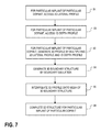
- FIG. 7 is a simplified process flow showing more detail on the step of generating 3D dopant distributions in FIG. 6 .
- FIG. 8 is a simplified block diagram of a computer system that can be used to implement aspects of the invention.
- FIG. 9 is a simplified representation of an illustrative integrated circuit design flow.
- FIG. 10 is a set of graphs showing the effects of remixing diffusion profiles.
- FIG. 11 is a set of concentration graphs showing the effects of remixing diffusion profiles.
- FIG. 12 shows the extraction of a decay length parameter from 1D lateral profiles.
- FIGS. 13 a -13 e show perspective views of part of a lithographic process flow and a flat 2D slice.
- FIG. 14 shows an initial dopant concentration in connection with FIGS. 13 a - e.
- FIGS. 15 a - c show one embodiment of generating a 2D lateral profile by convolving a mask image with a Gaussian.
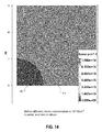
- FIG. 16 shows the 3D mesh with implanted dopant concentrations.
- FIGS. 17 a - e show one embodiment of generating a 2D lateral profile by using a solution of a diffusion equation with the mask as an initial condition.
- FIG. 18 shows the 2D mesh with implanted dopant concentrations.
- FIG. 19 is a simplified process flow showing more detail on the step of completing 3D dopant distributions, similar to FIG. 6 but based on diffusion rather than convolution.
- FIG. 1 is a simplified process flow of the improved simulation of a 3D fabrication process.
- the process flow is divided into the steps of building a database of process information step 10 , and completing a 3D dopant distribution based on the database step 12 .
- the database includes lateral spreading parameters and ID depth profiles for all implants of all dopants.
- the 3D dopant distributions are built based on the database and the masks of the layout. Step 10 is shown in more steps in FIG. 2 . Step 12 is shown in more steps in FIG. 6 .
- FIG. 2 is a simplified process flow showing more detail on the step of completing a database in FIG. 1 .
- a particular implant of a particular dopant is chosen.
- the implants can be elements on the periodic table or compounds thereof. Alternatively, this step can be the choice of a particular oxidation step.
- 2D process simulation is performed for the particular implant of the particular dopant.
- the 2D process simulation is performed for the particular oxidation. Step 24 is shown in more detail in FIG. 3 .
- a 3D process simulation is performed, and a 2D vertical slice is extracted, which is another way to perform 2D process simulation, though more computationally expensive.
- a 1D lateral profile is extracted from the 2D process simulation.
- a 1D depth profile is extracted from the 2D process simulation.
- An example is shown at FIG. 4 .
- the 2D process simulation can be separate simulations such that 1D lateral profile and the 1D depth profile are extracted from different 2D process simulations.
- the embodiment of extracting the 1D lateral profile and the 1D depth profile from the same 2D process simulation requires fewer processing resources.
- either embodiment is an example of performing process simulation to generate a 1D lateral profile of a dopant and a 1D depth profile of the first dopant.
- a lateral spreading parameter is extracted from the 1D lateral profile.
- An example is shown in FIG. 5 .
- the lateral spreading profile and the 1D depth profile are stored in one or more databases.
- the 1D lateral profile is stored instead of, or in addition to, the lateral spreading parameter. If the 1D lateral profile is stored, extraction of the lateral spreading parameter can be delayed until a later step, no later than when the lateral spreading parameter is needed.
- the process at least partly interleaves, and/or performs at least partly concurrently, calculations for different implants of the same dopant or different dopants.
- the database is completed of lateral spreading parameters and 1D depth profiles for all implants of all dopants, and all oxidations.
- the database stores the 2D process simulations, and extracts the lateral and vertical profiles and the lateral spreading parameter later.
- Various embodiments can reorder, add, remove, or change steps in the process flow.
- FIG. 3 is a simplified process flow showing more detail on the step of performing 2D process simulation in FIG. 1 .
- end-of-process conditions are generated for a particular implant of a particular dopant.
- end-of-process conditions are generated for a particular oxidation step.
- the end-of-process conditions consider not only temperatures and durations of thermal processes immediately after the particular implant of the particular dopant, but also temperatures and durations of subsequent thermal processes.
- test structures are used for generating the test lateral and test depth profiles.
- the test structures are based on basic polygonal shapes such as rectangular masks.
- the rectangular opening of the mask results in sufficient data to extract test lateral and test depth profiles.
- Other embodiments have different sized or shaped mask openings. Beyond the extracted test lateral and test depth profiles, the remainder of the 2D simulation results are discarded.
- more complicated masks may be used also, such complicated masks require more complicated 2D simulation that is unnecessary for the purpose of extracting the test lateral and test depth profiles.
- Step 44 uses a first mask to generate basic data.
- An end result of this overall technology is a simulation of a 2D doping distribution from adding a dopant through a second mask, taking advantage of the basic data gained with the first mask.
- the first and second masks are different.
- FIG. 4 shows a vertical 2D process simulation, and an example of generating test 1D lateral and 1D depth profiles.
- test 1D lateral profile 52 Shown are an example test 1D lateral profile 52 and an example test 1D depth profile.
- the purpose of this 2D process simulation was to generate the test 1D lateral and test 1D depth profiles for a particular implant of a particular dopant. Accordingly, the remainder of the results of this 2D process simulation can be discarded.
- the example test 1D lateral profile 52 is taken along the surface of the substrate.
- the example test 1D depth profile can be taken generally from about the middle of the mask opening.
- the figure of the 2D slice does not show the right portion of the mask opening, which during simulation can be omitted to take advantage of symmetry for faster simulation results.
- FIG. 5 shows examples of extracting lateral spreading parameter from test 1D lateral profiles.
- the graph includes lateral profiles 66 and 68 extracted from respective 2D process simulations.
- lateral spreading parameters are extracted from lateral profiles 66 and 68 by curve fitting an error function erf of the following form, with another scaling constant (not shown) for the maximum concentration:
- a respective lateral spreading parameter in this case the standard deviation, is extracted after performing a curve fit between erf(x) with various candidate standard deviations.
- the curve fit of 62 to 66 generates a lateral spreading parameter for the lateral profile 66 .
- the curve fit of 64 to 68 generates a lateral spreading parameter for the lateral profile 68 .
- a single quantity, the lateral spreading parameter a characterizes an entire curve.
- FIG. 6 is a simplified process flow showing more detail on the step of completing 3D dopant distributions in FIG. 1 .
- a particular implant of a particular dopant is chosen. These are the same set of dopants and the same set of implants as with step 22 of FIG. 2 . Alternatively, a particular oxidation is chosen as with step 22 of FIG. 2 .
- the lateral spreading parameter is accessed from the database.
- the lateral spreading parameter was stored in the database in 32 of FIG. 2 .
- a 2D lateral function is generated from the lateral spreading profile.
- the lateral spreading parameter for example, a standard deviation
- the Gaussian function of the following form, with another scaling constant (not shown):
- the 2D lateral function is convolved with the mask for the particular implant of the particular dopant, to generate the 2D lateral profile.
- the 2D lateral function is convolved with the mask for the particular oxidation, to generate the 2D lateral profile.
- the 2D lateral profile is obtained via another type of analytic implantation with the Gaussian function.
- analytic implantation generally requires a 3D mesh which is computationally expensive.
- the 1D depth profile is extracted from the database.
- the 1D depth profile was stored in the database in 32 of FIG. 2 .
- the 3D dopant distribution is generated from the 2D lateral profile and the 1D depth profile.
- the process at least partly interleaves, and/or performs at least partly concurrently, calculations for different implants of the same dopant or different dopants.
- Various embodiments can reorder, add, remove, or change steps in the process flow.
- implants behave differently under an oxidation such as LOCOS and active area. Accordingly, a given implant may be split into two masks: a first mask of the implant that overlaps with the oxidation such as LOCOS, and a second mask of the remainder.
- the software representations of an isolation mask and an implantation mask are processed to obtain the software representation of the intersection of the isolation mask and the implantation mask.
- This intersection area indicates where as-implanted ions hit isolation oxide such as STI or LOCOS.
- the intersection area and active area are treated with different 1D depth profiles and resulting 3D dopant distributions, despite representing the same dopant.
- Boolean manipulation of masks can take into account the shielding properties of materials that block implants.
- Another example is to take into account the shielding properties of gates such as polysilicon gates, for example by subtracting the gate area from the intersection area and the active area for an LDD implant.
- Another example is to take into account the shielding properties of spacers such as nitride spacers (such as when spacers extend the gate mask), for example by subtracting the spacer area from the intersection area and the active area.
- a device with a slightly different dose such as an NWELL dose, such as up to +/ ⁇ 10% can be simulated in different ways: rescale the old dose data without having to perform more process simulation, or perform more process simulation with the changed implantation dose.
- the simulation generates a 2D profile.
- the 1D depth profile is multiplied with a 1D lateral profile.
- the 1D lateral profile is generated by convolving the 1D slice of the mask with a 1D Gaussian function.
- the 2D dopant distribution corresponds to the region below the 1D slice of the mask.
- the 1D Gaussian function has the following form, with another scaling constant (not shown):
- FIG. 7 is a simplified process flow showing more detail on the step of generating 3D dopant distributions in FIG. 6 .
- a 3D profile is generated by multiplying the 2D lateral profile and the 1D depth profile.
- a 3D boundary structure is generated by boundary emulation.
- the 3D profile is interpolated onto the mesh of the 3D boundary structure.
- the 3D structure is completed for the particular implant of the particular dopant.
- the 3D structure is completed for the particular oxidation.
- FIG. 8 is a simplified block diagram of a computer system 110 that can be used to implement software incorporating aspects of the present invention. While the present paper indicates individual steps carrying out specified operations, it will be appreciated that each step is actually implemented with software instructions that cause the computer system 110 to operate in the specified manner.
- Computer system 110 typically includes a processor subsystem 114 which communicates with a number of peripheral devices via bus subsystem 112 .
- peripheral devices may include a storage subsystem 124 , comprising a memory subsystem 126 and a file storage subsystem 128 , user interface input devices 122 , user interface output devices 120 , and a network interface subsystem 116 .
- the input and output devices allow user interaction with computer system 110 .
- Network interface subsystem 116 provides an interface to outside networks, including an interface to communication network 118 , and is coupled via communication network 118 to corresponding interface devices in other computer systems.
- Communication network 118 may comprise many interconnected computer systems and communication links. These communication links may be wireline links, optical links, wireless links, or any other mechanisms for communication of information. While in one embodiment, communication network 118 is the Internet, in other embodiments, communication network 118 may be any suitable computer network.
- NICs network interface cards
- ICs integrated circuits
- ICs integrated circuits
- macrocells fabricated on a single integrated circuit chip with other components of the computer system.
- User interface input devices 122 may include a keyboard, pointing devices such as a mouse, trackball, touchpad, or graphics tablet, a scanner, a touch screen incorporated into the display, audio input devices such as voice recognition systems, microphones, and other types of input devices.
- pointing devices such as a mouse, trackball, touchpad, or graphics tablet
- audio input devices such as voice recognition systems, microphones, and other types of input devices.
- use of the term “input device” is intended to include all possible types of devices and ways to input information into computer system 110 or onto computer network 118 .
- User interface output devices 120 may include a display subsystem, a printer, a fax machine, or nonvisual displays such as audio output devices.
- the display subsystem may include a cathode ray tube (CRT), a flat panel device such as a liquid crystal display (LCD), a projection device, or some other mechanism for creating a visible image.
- the display subsystem may also provide non visual display such as via audio output devices.
- output device is intended to include all possible types of devices and ways to output information from computer system 110 to the user or to another machine or computer system.
- Storage subsystem 124 stores the basic programming and data constructs that provide the functionality of certain embodiments of the present invention.
- the various modules implementing the functionality of certain embodiments of the invention may be stored in storage subsystem 124 .
- Some examples are a tool for generating 3D dopant distributions or 3D oxidations based on lateral spreading parameters extracted from 1D test lateral profiles; and a tool for generating a database of 1D vertical profiles and lateral spreading parameters. These software modules are generally executed by processor subsystem 114 .
- Storage subsystem 124 also represents storage accessible to the computer system on which the various databases mentioned herein are stored.
- Storage subsystem 124 can store the database of 1D vertical profiles and lateral spreading profiles; and a tool for generating a database of 1D vertical profiles and lateral spreading parameters.
- the tool accesses the local or remote database of 1D vertical profiles and lateral spreading parameters, or in combination both generates and accesses the database.
- some or all of the databases are located on storage accessible to the computer system via the network
- Memory subsystem 126 typically includes a number of memories including a main random access memory (RAM) 130 for storage of instructions and data during program execution and a read only memory (ROM) 132 in which fixed instructions are stored.
- File storage subsystem 128 provides persistent storage for program and data files, and may include a hard disk drive, a floppy disk drive along with associated removable media, a CD ROM drive, an optical drive, or removable media cartridges.
- the databases and modules implementing the functionality of certain embodiments of the invention may have been provided on a computer readable medium such as one or more CD-ROMs, and may be stored by file storage subsystem 128 .
- the host memory 126 contains, among other things, computer instructions which, when executed by the processor subsystem 114 , cause the computer system to operate or perform functions as described herein. As used herein, processes and software that are said to run in or on “the host” or “the computer”, execute on the processor subsystem 114 in response to computer instructions and data in the host memory subsystem 126 including any other local or remote storage for such instructions and data.
- Bus subsystem 112 provides a mechanism for letting the various components and subsystems of computer system 110 communicate with each other as intended. Although bus subsystem 112 is shown schematically as a single bus, alternative embodiments of the bus subsystem may use multiple busses.
- Computer system 110 itself can be of varying types including a personal computer, a portable computer, a workstation, a computer terminal, a network computer, a television, a mainframe, a server farm, or any other data processing system or user device. Due to the ever changing nature of computers and networks, the description of computer system 110 depicted in FIG. 8 is intended only as a specific example for purposes of illustrating certain embodiments of the present invention. Many other configurations of computer system 110 are possible having more or less components than the computer system depicted in FIG. 8 .
- FIG. 9 shows a simplified representation of an illustrative integrated circuit design flow incorporating features of the technology.
- the process starts with the product idea (step 200 ) and is realized in an EDA (Electronic Design Automation) software design process (step 210 ).
- EDA Electronic Design Automation
- the design can be taped-out (step 227 ).
- the fabrication process step 250
- packaging and assembly processes step 260
- the EDA software design process (step 210 ) is actually composed of a number of steps 212 - 230 , shown in linear fashion for simplicity.
- the particular design might have to go back through steps until certain tests are passed.
- these steps may occur in different orders and combinations. This description is therefore provided by way of context and general explanation rather than as a specific, or recommended, design flow for a particular integrated circuit.
- step 210 A brief description of the components steps of the EDA software design process (step 210 ) will now be provided.
- System design (step 212 ): The designers describe the functionality that they want to implement, they can perform what-if planning to refine functionality, check costs, etc. Hardware-software architecture partitioning can occur at this stage.
- Example EDA software products from Synopsys, Inc. that can be used at this step include Model Architect, Saber, System Studio, and DesignWare® products.
- Logic design and functional verification (step 214 ): At this stage, the VHDL or Verilog code for modules in the system is written and the design is checked for functional accuracy. More specifically, the design is checked to ensure that produces the correct outputs in response to particular input stimuli.
- Example EDA software products from Synopsys, Inc. that can be used at this step include VCS, VERA, DesignWare®, Magellan, Formality, ESP and LEDA products.
- Synthesis and design for test (step 216 ): Here, the VHDL/Verilog is translated to a netlist.
- the netlist can be optimized for the target technology. Additionally, the design and implementation of tests to permit checking of the finished chip occurs.
- Example EDA software products from Synopsys, Inc. that can be used at this step include Design Compiler®, Physical Compiler, Test Compiler, Power Compiler, FPGA Compiler, Tetramax, and DesignWare® products.
- Netlist verification (step 218 ): At this step, the netlist is checked for compliance with timing constraints and for correspondence with the VHDL/Verilog source code.
- Example EDA software products from Synopsys, Inc. that can be used at this step include Formality, PrimeTime, and VCS products.
- Design planning (step 220 ): Here, an overall floor plan for the chip is constructed and analyzed for timing and top-level routing.
- Example EDA software products from Synopsys, Inc. that can be used at this step include Astro and IC Compiler products.
- step 222 The placement (positioning of circuit elements) and routing (connection of the same) occurs at this step.
- Example EDA software products from Synopsys, Inc. that can be used at this step include the Astro and IC Compiler products.
- step 224 the circuit function is verified at a transistor level, this in turn permits what-if refinement.
- Example EDA software products from Synopsys, Inc. that can be used at this step include AstroRail, PrimeRail, Primetime, and Star RC/XT products.
- step 226 Physical verification: At this step various checking functions are performed to ensure correctness for: manufacturing, electrical issues, lithographic issues, and circuitry.
- Example EDA software products from Synopsys, Inc. that can be used at this step include the Hercules product.
- Tape-out (step 227 ): This step provides the “tape out” data for production of masks for lithographic use to produce finished chips.
- Example EDA software products from Synopsys, Inc. that can be used at this step include the CATS® family of products.
- Resolution enhancement (step 228 ): This step involves geometric manipulations of the layout to improve manufacturability of the design.
- Example EDA software products from Synopsys, Inc. that can be used at this step include Proteus, ProteusAF, and PSMGen products.
- Mask data preparation (step 230 ): This step provides the “tape-out” data for production of masks for lithographic use to produce finished chips.
- Example EDA software products from Synopsys, Inc. that can be used at this step include the CATS® family of products.
- a typical integrated circuit manufacturing flow also includes a parallel flow, as follows:
- the input information here include masks or layout information, and process conditions like temperature, reactor ambient, implant energy, etc.
- the output information is the final geometry or doping profiles or stress distribution. Aspects of the invention can be used in this step of the manufacturing flow.
- the input information here includes the layout information and the collection of the process steps in the appropriate sequence.
- the output includes the geometry, the doping profiles, and the stress distribution for the transistors and the space in between the transistors. Aspects of the invention can be used also in this step of the manufacturing flow.
- the input information here includes the output of step (2) and the biases applied to transistor terminals.
- the output information includes the currents and capacitances for each bias combination.
- the process flow 212 - 230 will be used by such designers.
- the parallel flow described here is used at a foundry to develop a process flow that can be used to manufacture designs coming from the designers.
- a combination of the process flow and the masks made from step 230 are used to manufacture any particular circuit. If the designers are at a different company, e.g. a fabless company, then usually it is the foundry that performs this parallel process flow whereas the process steps of FIG. 9 are performed typically by the fabless company.
- the integrated circuit is manufactured at an IDM (integrated device manufacturer) company instead of the combination of a fabless company and a foundry, then both parallel flows described above are done at the same IDM company.
- the bridge is a Synopsys tool “Seismos” that applies compact proximity models for particular circuit design and layout to obtain netlist with instance parameters for each individual transistor in the circuit as a function of its neighborhood and stress, including material conversion stress. This netlist is used in the analysis step 224 .
- FIG. 10 is a set of graphs showing the effects of remixing diffusion profiles.
- FIG. 11 is a set of concentration graphs showing the effects of remixing diffusion profiles, corresponding to FIG. 10 .
- the remix operation addresses the doping artifacts appearing in the transition region between active area and isolation area.
- the example shows a gate with spacers overlapping an STI (shallow trench isolation oxide).
- profile 1002 before remix ends at the bottom of the STI to indicate zero active doping concentration within the STI region (typically oxide) because dopants are inactive in insulators.
- the active profile 1001 extends until the Si surface.
- artifacts 1105 and 1106 result in FIG. 11 , shown as an active dopant concentration abnormally dropping-off nearby the STI edges, from about 10 17 cm ⁇ 3 below the STI to about 5 ⁇ 10 16 cm ⁇ 3 in just under Si on both sides of the STI.
- FIG. 12 shows the extraction of a decay length parameter from 1D lateral profiles.
- the example shows lateral profiles for different dopants boron and arsenic, with respective spreading parameters, in this case decay lengths in an error function.
- profile 164 is the simulated lateral profile of boron
- 168 is the fitted lateral profile of boron
- Profile 162 is the simulated lateral profile of arsenic
- 166 is the fitted lateral profile of arsenic.
- 1D fitted profile is used:
- FIGS. 13 a -13 d show perspective views of part of a lithographic process flow used in several of the following figures.
- photoresist is formed lithographically to cover region 302 but not region 304 .
- silicon is etched in region 304 uncovered by the photoresist, resulting in etched region 306 .
- the photoresist is stripped, leaving stripped region 308 and etched region 306 .
- oxide is deposited in etched region 306 to form an oxide region 310 .
- FIG. 13 e shows a flat 2D slice of FIG. 13 d , with stripped region 308 and oxide region 310 .
- FIG. 14 shows an initial dopant concentration in connection with the lithographic process of FIGS. 13 a - d and the flat 2D slice in FIG. 13 e .
- the boron concentration is 10 16 cm ⁇ 3 in oxide region 410 , and is zero in the silicon 408 of the stripped region.
- FIGS. 15-16 show one embodiment of generating a 2D lateral profile, in which a 3D mesh is generated in order to generate the 2D lateral profile.
- FIG. 15 a shows a sharp mask image, which indicates good results for the convolution technique.
- Masks generally can be broken down into basic shapes such as FIG. 15 a .
- FIG. 15 b shows a 2D lateral function, in this case a Gaussian function, to represent the movement of dopants, having the following form:
- FIG. 15 c shows the convolution result of a Gaussian blur.
- FIG. 16 shows the 3D mesh with implanted dopant concentrations at various depths of the 3D mesh being determined by the Gaussian blur.
- the 3D mesh scale is normalized with 1 being the peak concentration.
- FIGS. 17-18 show another embodiment of generating a 2D lateral profile, in which a 2D mesh rather than a 3D mesh can be generated in order to generate the 2D lateral profile.
- FIG. 17 a shows a sharp mask image, which indicates good results for the diffusion technique.
- Masks generally can be broken down into basic shapes such as FIG. 17 a .
- FIG. 17 b shows a diffusion equation, to represent the movement of dopants, having the following form:
- the 1D diffusion formula is as follows:
- FIG. 15 c shows the diffusion equation solution resulting from the initial conditions for diffusion as represented by the sharp mask image of FIG. 17 a.
- ⁇ ⁇ ( x ) C max 2 [ 1 + erf ⁇ ( x 2 ⁇ D ⁇ ⁇ ⁇ ) ]
- the 2D diffusion formula is as follows:
- the 2D diffusion formula presents similar solutions to the 1D diffusion formula but with a cylindrical distribution.
- FIG. 18 shows 2D mesh with implanted dopant concentration being determined by a solution to the diffusion equation.
- the 2D mesh scale is normalized with 1 being the peak concentration.
- FIG. 19 is a simplified process flow showing more detail on the step of completing 3D dopant distributions in FIG. 1 , similar to FIG. 6 but based on diffusion rather than convolution.
- the process flow is similar between FIGS. 6 and 19 .
- the 2D lateral function is based on a solution to the diffusion equation.
- the 2D lateral profile is generated from the 2D lateral function which can be based on a solution to a diffusion equation, with initial dopant conditions based on the mask of photoresist layer based on the mask for the particular implant of the particular dopant or the mask for the particular oxidation, to generate the 2D lateral profile.
Landscapes
- Engineering & Computer Science (AREA)
- Computer Hardware Design (AREA)
- Physics & Mathematics (AREA)
- Theoretical Computer Science (AREA)
- Evolutionary Computation (AREA)
- Geometry (AREA)
- General Engineering & Computer Science (AREA)
- General Physics & Mathematics (AREA)
- Microelectronics & Electronic Packaging (AREA)
- Design And Manufacture Of Integrated Circuits (AREA)
Priority Applications (1)
| Application Number | Priority Date | Filing Date | Title |
|---|---|---|---|
| US14/699,162 US10410862B2 (en) | 2014-05-02 | 2015-04-29 | 3D TCAD simulation |
Applications Claiming Priority (4)
| Application Number | Priority Date | Filing Date | Title |
|---|---|---|---|
| US201461987766P | 2014-05-02 | 2014-05-02 | |
| US201462011724P | 2014-06-13 | 2014-06-13 | |
| US201462016943P | 2014-06-25 | 2014-06-25 | |
| US14/699,162 US10410862B2 (en) | 2014-05-02 | 2015-04-29 | 3D TCAD simulation |
Publications (2)
| Publication Number | Publication Date |
|---|---|
| US20150317420A1 US20150317420A1 (en) | 2015-11-05 |
| US10410862B2 true US10410862B2 (en) | 2019-09-10 |
Family
ID=54355419
Family Applications (1)
| Application Number | Title | Priority Date | Filing Date |
|---|---|---|---|
| US14/699,162 Active 2036-10-13 US10410862B2 (en) | 2014-05-02 | 2015-04-29 | 3D TCAD simulation |
Country Status (6)
| Country | Link |
|---|---|
| US (1) | US10410862B2 (de) |
| EP (1) | EP3138028A4 (de) |
| JP (1) | JP6393407B2 (de) |
| CN (1) | CN106415553B (de) |
| TW (1) | TWI576715B (de) |
| WO (1) | WO2015168273A1 (de) |
Cited By (1)
| Publication number | Priority date | Publication date | Assignee | Title |
|---|---|---|---|---|
| US12182486B2 (en) | 2021-03-26 | 2024-12-31 | Samsung Electronics Co., Ltd. | System and method for modeling damages caused by incident particles |
Families Citing this family (4)
| Publication number | Priority date | Publication date | Assignee | Title |
|---|---|---|---|---|
| US10411135B2 (en) | 2015-06-08 | 2019-09-10 | Synopsys, Inc. | Substrates and transistors with 2D material channels on 3D geometries |
| KR102580947B1 (ko) * | 2018-06-29 | 2023-09-20 | 삼성전자주식회사 | 추출된 모델 파라미터를 이용하여 집적 회로를 설계하기 위한 컴퓨팅 시스템 및 이를 이용한 집적 회로의 제조 방법 |
| US11693386B2 (en) | 2019-08-27 | 2023-07-04 | Samsung Eleotronics Co., Ltd. | Method and electronic device for guiding semiconductor manufacturing process |
| TWI824233B (zh) * | 2020-02-12 | 2023-12-01 | 美商新思科技股份有限公司 | 具有漏電流中的統計變化之動態隨機存取記憶體通路電晶體的設計 |
Citations (15)
| Publication number | Priority date | Publication date | Assignee | Title |
|---|---|---|---|---|
| US4536945A (en) * | 1983-11-02 | 1985-08-27 | National Semiconductor Corporation | Process for producing CMOS structures with Schottky bipolar transistors |
| US5245543A (en) | 1990-12-21 | 1993-09-14 | Texas Instruments Incorporated | Method and apparatus for integrated circuit design |
| JPH06290240A (ja) | 1993-03-31 | 1994-10-18 | Toshiba Corp | シミュレーション方法 |
| US5889678A (en) | 1996-08-22 | 1999-03-30 | Kabushiki Kaisha Toshiba | Topography simulation method |
| JP2002270478A (ja) | 2000-12-21 | 2002-09-20 | Toshiba Corp | 電子回路設計シミュレータ |
| US6645854B1 (en) | 2000-07-11 | 2003-11-11 | National Semiconductor Corporation | Formation of a vertical junction throuph process simulation based optimization of implant doses and energies |
| US20050145930A1 (en) * | 2003-12-24 | 2005-07-07 | Texas Instruments, Incorporated | High voltage drain-extended transistor |
| JP2005217230A (ja) | 2004-01-30 | 2005-08-11 | Toshiba Corp | イオン注入シミュレーション装置、イオン注入シミュレーション方法、イオン注入シミュレーションプログラム及びイオン注入シミュレーションプログラムを記録したコンピュータ読み取り可能な記録媒体 |
| JP2007019173A (ja) | 2005-07-06 | 2007-01-25 | Matsushita Electric Ind Co Ltd | 不純物拡散シミュレーション方法、不純物拡散シミュレーション装置、及び、不純物拡散シミュレーションプログラム |
| TWI284423B (en) | 2004-06-04 | 2007-07-21 | Univ Illinois | Methods and devices for fabricating and assembling printable semiconductor elements |
| TW200836353A (en) | 2006-09-06 | 2008-09-01 | Univ Illinois | Controlled buckling structures in semiconductor interconnects and nanomembranes for stretchable electronics |
| US7846822B2 (en) | 2004-07-30 | 2010-12-07 | The Board Of Trustees Of The University Of Illinois | Methods for controlling dopant concentration and activation in semiconductor structures |
| JP2012209536A (ja) | 2011-03-11 | 2012-10-25 | Sony Corp | イオン注入シミュレーション方法及びイオン注入シミュレーション装置、半導体装置の製造方法、半導体装置の設計方法 |
| US20130194577A1 (en) | 2010-07-21 | 2013-08-01 | Katholieke Universiteit Leuven | Method for determining an active dopant profile |
| US20130313620A1 (en) | 2004-02-17 | 2013-11-28 | Silicon Space Technology Corporation | Method and structure for radiation hardening a semiconductor device |
Family Cites Families (1)
| Publication number | Priority date | Publication date | Assignee | Title |
|---|---|---|---|---|
| US7100131B2 (en) * | 2002-11-07 | 2006-08-29 | Semiconductor Energy/Laboratory Co., Ltd. | Evaluation method of semiconductor device, manufacturing method of the semiconductor device, design management system of device comprising the semiconductor device, dose amount control program for the semiconductor device, computer-readable recording medium recording the program, and dose amount control apparatus |
-
2015
- 2015-04-29 EP EP15785526.3A patent/EP3138028A4/de not_active Ceased
- 2015-04-29 WO PCT/US2015/028276 patent/WO2015168273A1/en not_active Ceased
- 2015-04-29 US US14/699,162 patent/US10410862B2/en active Active
- 2015-04-29 TW TW104113718A patent/TWI576715B/zh active
- 2015-04-29 CN CN201580029422.4A patent/CN106415553B/zh active Active
- 2015-04-29 JP JP2017509604A patent/JP6393407B2/ja active Active
Patent Citations (17)
| Publication number | Priority date | Publication date | Assignee | Title |
|---|---|---|---|---|
| US4536945A (en) * | 1983-11-02 | 1985-08-27 | National Semiconductor Corporation | Process for producing CMOS structures with Schottky bipolar transistors |
| US5245543A (en) | 1990-12-21 | 1993-09-14 | Texas Instruments Incorporated | Method and apparatus for integrated circuit design |
| JPH06290240A (ja) | 1993-03-31 | 1994-10-18 | Toshiba Corp | シミュレーション方法 |
| US5889678A (en) | 1996-08-22 | 1999-03-30 | Kabushiki Kaisha Toshiba | Topography simulation method |
| US6645854B1 (en) | 2000-07-11 | 2003-11-11 | National Semiconductor Corporation | Formation of a vertical junction throuph process simulation based optimization of implant doses and energies |
| JP2002270478A (ja) | 2000-12-21 | 2002-09-20 | Toshiba Corp | 電子回路設計シミュレータ |
| US20050145930A1 (en) * | 2003-12-24 | 2005-07-07 | Texas Instruments, Incorporated | High voltage drain-extended transistor |
| JP2005217230A (ja) | 2004-01-30 | 2005-08-11 | Toshiba Corp | イオン注入シミュレーション装置、イオン注入シミュレーション方法、イオン注入シミュレーションプログラム及びイオン注入シミュレーションプログラムを記録したコンピュータ読み取り可能な記録媒体 |
| US20130313620A1 (en) | 2004-02-17 | 2013-11-28 | Silicon Space Technology Corporation | Method and structure for radiation hardening a semiconductor device |
| TWI284423B (en) | 2004-06-04 | 2007-07-21 | Univ Illinois | Methods and devices for fabricating and assembling printable semiconductor elements |
| US8664699B2 (en) | 2004-06-04 | 2014-03-04 | The Board Of Trustees Of The University Of Illinois | Methods and devices for fabricating and assembling printable semiconductor elements |
| US7846822B2 (en) | 2004-07-30 | 2010-12-07 | The Board Of Trustees Of The University Of Illinois | Methods for controlling dopant concentration and activation in semiconductor structures |
| JP2007019173A (ja) | 2005-07-06 | 2007-01-25 | Matsushita Electric Ind Co Ltd | 不純物拡散シミュレーション方法、不純物拡散シミュレーション装置、及び、不純物拡散シミュレーションプログラム |
| TW200836353A (en) | 2006-09-06 | 2008-09-01 | Univ Illinois | Controlled buckling structures in semiconductor interconnects and nanomembranes for stretchable electronics |
| US20130194577A1 (en) | 2010-07-21 | 2013-08-01 | Katholieke Universiteit Leuven | Method for determining an active dopant profile |
| US20120276723A1 (en) | 2011-03-11 | 2012-11-01 | Sony Corporation | Ion injection simulation method, ion injection simulation device, method of producing semiconductor device, and method of designing semiconductor device |
| JP2012209536A (ja) | 2011-03-11 | 2012-10-25 | Sony Corp | イオン注入シミュレーション方法及びイオン注入シミュレーション装置、半導体装置の製造方法、半導体装置の設計方法 |
Non-Patent Citations (26)
| Title |
|---|
| Antoniadis, Dimitri A., and Robert W. Dutton. "Models for computer simulation of complete IC fabrication process." IEEE Journal of Solid-State Circuits 14.2 (1979): 412-422. * |
| Antoniadis, Dimitri A., and Robert W. Dutton. "Models for computer simulation of complete IC fabrication process." IEEE Journal of Solid-State Circuits 14.2 (1979): 412-422. (Year: 1979). * |
| Bar et al, "Experimental Verification of Three-Dimensional Simulations of LTO Layer Deposition on Structures Prepared by Anisotropic Wet Etching of Silicon", Microelectronics & Reliability, Elsevier Science LTD, GB, vol. 38, No. 2, Feb. 27, 1998, pp. 287-291, XPO27119448, ISSN: 0026-2714. |
| Colombeau et al., "Design and Optimization of nanoCMOS devices using predictive atomistic physics-based process modeling", 2006 International Electron Devices Meeting, IEEE Conferences, pp. 1-4, Chartered Semiconductor Ltd, Singapore 738406, Department of Electronics, University of Valladolid, 47011, Spain, Advanced Technology Institute, University of Surrey, UK. |
| D.J. GODFREY; GEC HIRST RES. CENTRE, WEMBLEY, UK;: "Modelling physical processes in silicon integrated circuit fabrication", PHYSICS IN TECHNOLOGY, INSTITUTE OF PHYSICS PUBLISHING, BRISTOL, GB, vol. 17, no. 6, 1 November 1986 (1986-11-01), GB, pages 260 - 264, XP020048051, ISSN: 0305-4624, DOI: 10.1088/0305-4624/17/6/I03 |
| EP 15785526-3—Extended European Search Report dated Jan. 4, 2018. |
| EP 15785526-3—Response to Extended European Search Report dated Jan. 4, 2018 filed Aug. 2, 2018, 12 pages. |
| Fichtner et al., "Multi-Dimensional Process Simulation Software Integration in Prompt", ISL, Swiss Federal Inst. of Technology and ISE Integrated Systems Engineering AG, Zurich, Switzerland, Solid State Device Research Conference, 1996, Proceedings of the 26th European, IEEE, Piscataway, NJ, USA, Sep. 9, 1996, ISBN: 978-2-86332-196-6, pp. 335-342. |
| Fichtner, W., and P. Regli. "Multi-dimensional process simulation software integration in Prompt." Solid State Device Research Conference, 1996. ESSDERC'96. Proceedings of the 26th European. IEEE, 1996. (Year: 1996). * |
| Furukawa, Seijiro, Hideki Matsumura, and Hiroshi Ishiwara. "Theoretical considerations on lateral spread of implanted ions." Japanese Journal of Applied Physics 11.2 (1972): 134. * |
| Furukawa, Seijiro, Hideki Matsumura, and Hiroshi Ishiwara. "Theoretical considerations on lateral spread of implanted ions." Japanese Journal of Applied Physics 11.2 (1972): 134. (Year: 1972). * |
| Godfrey, "Modelling Physical Processes in Silicon Integrated Circuit Fabrication", Physics in Technology, Institute of Physics Publishing, Bristol, GB, vol. 17, No. 6, Nov. 1, 1976, pp. 260-264, XP020048051, ISSN: 0305-4624. |
| International Search Report dated Jul. 28, 2015 for PCT Application No. PCT/US2015/028276. |
| JP 2017-509604—First Office Action dated Feb. 6, 2018, 9 pages. |
| JP 2017-509604—Notice of Allowance dated Aug. 7, 2018, 7 pages. |
| JP 2017-509604—Response to First Office Action dated Feb. 6, 2018 filed Jul. 23, 2018, 9 pages. |
| Nakagawa, S. T. "The high-fluence effect on the lateral spread of ions within a masked target." Materials chemistry and physics 54.1-3 (1998): 28-32. * |
| Nakagawa, S. T. "The high-fluence effect on the lateral spread of ions within a masked target." Materials chemistry and physics 54.1-3 (1998): 28-32. (Year: 1998). * |
| PCT/US2015/028276—International Preliminary Report on Patentability dated Nov. 8, 2016, 9 pages. |
| Ryssel, H., L. Gong, and J. Lorenz. "Improvements in simulation of 2D implantation profiles." VLSI Technology, Systems and Applications, 1989. Proceedings of Technical Papers. 1989 International Symposium on. IEEE, 1989. * |
| Ryssel, H., L. Gong, and J. Lorenz. "Improvements in simulation of 2D implantation profiles." VLSI Technology, Systems and Applications, 1989. Proceedings of Technical Papers. 1989 International Symposium on. IEEE, 1989. (Year: 1989). * |
| Senez et al., "3-Dimensional Process Simulation of Thermal Annealing of Low Dose Implanted Dopants in Silicon", IEICE Trans Electron, vol. E83-C, No. 8, Aug. 2000, pp. 1267-1274. |
| Thompson et al. "Three-dimensional atom mapping of dopants in Si nanostructures," Applied Physics Letters 87.5 (2005):052108, 3 pages. |
| Thompson, Keith, et al. "Three-dimensional atom mapping of dopants in Si nanostructures." Applied Physics Letters 87.5 (2005): 052108. (Year: 2005). * |
| TW Office Action from counterpart Application No. TW104113718 dated Jul. 25, 2016, 16 pages. |
| Vandervorst, Wilfried, et al. "Dopant/carrier profiling for 3D-structures." physica status solidi (c) 11.1 (2014): 121-129. (Year: 2014). * |
Cited By (1)
| Publication number | Priority date | Publication date | Assignee | Title |
|---|---|---|---|---|
| US12182486B2 (en) | 2021-03-26 | 2024-12-31 | Samsung Electronics Co., Ltd. | System and method for modeling damages caused by incident particles |
Also Published As
| Publication number | Publication date |
|---|---|
| CN106415553B (zh) | 2020-06-02 |
| EP3138028A1 (de) | 2017-03-08 |
| WO2015168273A1 (en) | 2015-11-05 |
| TWI576715B (zh) | 2017-04-01 |
| EP3138028A4 (de) | 2018-01-24 |
| TW201606546A (zh) | 2016-02-16 |
| CN106415553A (zh) | 2017-02-15 |
| JP6393407B2 (ja) | 2018-09-19 |
| US20150317420A1 (en) | 2015-11-05 |
| JP2017520127A (ja) | 2017-07-20 |
Similar Documents
| Publication | Publication Date | Title |
|---|---|---|
| KR102396699B1 (ko) | 셀 레벨 레이아웃 의존성 응력 효과들을 사용하는 셀의 배치 및 라우팅 | |
| US8543958B2 (en) | Optical proximity correction aware integrated circuit design optimization | |
| US7542891B2 (en) | Method of correlating silicon stress to device instance parameters for circuit simulation | |
| US10410862B2 (en) | 3D TCAD simulation | |
| US10606968B2 (en) | Atomic scale grid for modeling semiconductor structures and fabrication processes | |
| US20110197170A1 (en) | Active Net Based Approach for Circuit Characterization | |
| US9477798B1 (en) | Moving mesh system and method for finite element/finite volume simulations | |
| US8706467B2 (en) | Compact circuit-simulation output | |
| US8627253B2 (en) | Method for substrate noise analysis | |
| US20110107293A1 (en) | Simulation-based design state snapshotting in electronic design automation | |
| WO2015048437A1 (en) | Mapping intermediate material properties to target properties to screen materials | |
| US7996795B2 (en) | Method and apparatus for performing stress modeling of integrated circuit material undergoing material conversion | |
| US11397840B1 (en) | Edge placement errors for optical lithography | |
| US8650020B1 (en) | Modeling second order effects for simulating transistor behavior | |
| WO2017075409A1 (en) | Atomic structure optimization | |
| US10706209B2 (en) | Estimation of effective channel length for FinFETs and nano-wires | |
| US10483171B2 (en) | Method and apparatus with channel stop doped devices | |
| CN111143767A (zh) | 统计模型的开发方法及开发系统 | |
| Li et al. | Variability-aware double-patterning layout optimization for analog circuits |
Legal Events
| Date | Code | Title | Description |
|---|---|---|---|
| AS | Assignment |
Owner name: SYNOPSYS, INC., CALIFORNIA Free format text: ASSIGNMENT OF ASSIGNORS INTEREST;ASSIGNOR:TERTERIAN, ARSEN;REEL/FRAME:035786/0674 Effective date: 20150603 Owner name: SYNOPSYS, INC., CALIFORNIA Free format text: ASSIGNMENT OF ASSIGNORS INTEREST;ASSIGNOR:CILENTO, TOMMASO;REEL/FRAME:035786/0585 Effective date: 20150603 |
|
| STPP | Information on status: patent application and granting procedure in general |
Free format text: NON FINAL ACTION MAILED |
|
| STPP | Information on status: patent application and granting procedure in general |
Free format text: RESPONSE TO NON-FINAL OFFICE ACTION ENTERED AND FORWARDED TO EXAMINER |
|
| STPP | Information on status: patent application and granting procedure in general |
Free format text: NOTICE OF ALLOWANCE MAILED -- APPLICATION RECEIVED IN OFFICE OF PUBLICATIONS |
|
| STPP | Information on status: patent application and granting procedure in general |
Free format text: AWAITING TC RESP, ISSUE FEE PAYMENT VERIFIED |
|
| STPP | Information on status: patent application and granting procedure in general |
Free format text: PUBLICATIONS -- ISSUE FEE PAYMENT VERIFIED |
|
| STCF | Information on status: patent grant |
Free format text: PATENTED CASE |
|
| MAFP | Maintenance fee payment |
Free format text: PAYMENT OF MAINTENANCE FEE, 4TH YEAR, LARGE ENTITY (ORIGINAL EVENT CODE: M1551); ENTITY STATUS OF PATENT OWNER: LARGE ENTITY Year of fee payment: 4 |