US10443205B2 - Concrete foundation, method for producing a concrete foundation for a wind power tower, and positioning device for positioning jacket pipes in a concrete foundation - Google Patents
Concrete foundation, method for producing a concrete foundation for a wind power tower, and positioning device for positioning jacket pipes in a concrete foundation Download PDFInfo
- Publication number
- US10443205B2 US10443205B2 US14/893,612 US201414893612A US10443205B2 US 10443205 B2 US10443205 B2 US 10443205B2 US 201414893612 A US201414893612 A US 201414893612A US 10443205 B2 US10443205 B2 US 10443205B2
- Authority
- US
- United States
- Prior art keywords
- positioning aid
- formwork
- concrete foundation
- core element
- positioning
- Prior art date
- Legal status (The legal status is an assumption and is not a legal conclusion. Google has not performed a legal analysis and makes no representation as to the accuracy of the status listed.)
- Expired - Fee Related, expires
Links
Images


Classifications
-
- E—FIXED CONSTRUCTIONS
- E02—HYDRAULIC ENGINEERING; FOUNDATIONS; SOIL SHIFTING
- E02D—FOUNDATIONS; EXCAVATIONS; EMBANKMENTS; UNDERGROUND OR UNDERWATER STRUCTURES
- E02D27/00—Foundations as substructures
- E02D27/32—Foundations for special purposes
- E02D27/42—Foundations for poles, masts or chimneys
- E02D27/425—Foundations for poles, masts or chimneys specially adapted for wind motors masts
-
- E—FIXED CONSTRUCTIONS
- E02—HYDRAULIC ENGINEERING; FOUNDATIONS; SOIL SHIFTING
- E02D—FOUNDATIONS; EXCAVATIONS; EMBANKMENTS; UNDERGROUND OR UNDERWATER STRUCTURES
- E02D27/00—Foundations as substructures
- E02D27/32—Foundations for special purposes
- E02D27/42—Foundations for poles, masts or chimneys
-
- E—FIXED CONSTRUCTIONS
- E02—HYDRAULIC ENGINEERING; FOUNDATIONS; SOIL SHIFTING
- E02D—FOUNDATIONS; EXCAVATIONS; EMBANKMENTS; UNDERGROUND OR UNDERWATER STRUCTURES
- E02D27/00—Foundations as substructures
- E02D27/32—Foundations for special purposes
- E02D27/50—Anchored foundations
-
- E—FIXED CONSTRUCTIONS
- E02—HYDRAULIC ENGINEERING; FOUNDATIONS; SOIL SHIFTING
- E02D—FOUNDATIONS; EXCAVATIONS; EMBANKMENTS; UNDERGROUND OR UNDERWATER STRUCTURES
- E02D31/00—Protective arrangements for foundations or foundation structures; Ground foundation measures for protecting the soil or the subsoil water, e.g. preventing or counteracting oil pollution
-
- E—FIXED CONSTRUCTIONS
- E04—BUILDING
- E04C—STRUCTURAL ELEMENTS; BUILDING MATERIALS
- E04C5/00—Reinforcing elements, e.g. for concrete; Auxiliary elements therefor
- E04C5/08—Members specially adapted to be used in prestressed constructions
- E04C5/12—Anchoring devices
-
- F—MECHANICAL ENGINEERING; LIGHTING; HEATING; WEAPONS; BLASTING
- F03—MACHINES OR ENGINES FOR LIQUIDS; WIND, SPRING, OR WEIGHT MOTORS; PRODUCING MECHANICAL POWER OR A REACTIVE PROPULSIVE THRUST, NOT OTHERWISE PROVIDED FOR
- F03D—WIND MOTORS
- F03D13/00—Assembly, mounting or commissioning of wind motors; Arrangements specially adapted for transporting wind motor components
- F03D13/20—Arrangements for mounting or supporting wind motors; Masts or towers for wind motors
- F03D13/22—Foundations specially adapted for wind motors
-
- Y—GENERAL TAGGING OF NEW TECHNOLOGICAL DEVELOPMENTS; GENERAL TAGGING OF CROSS-SECTIONAL TECHNOLOGIES SPANNING OVER SEVERAL SECTIONS OF THE IPC; TECHNICAL SUBJECTS COVERED BY FORMER USPC CROSS-REFERENCE ART COLLECTIONS [XRACs] AND DIGESTS
- Y02—TECHNOLOGIES OR APPLICATIONS FOR MITIGATION OR ADAPTATION AGAINST CLIMATE CHANGE
- Y02E—REDUCTION OF GREENHOUSE GAS [GHG] EMISSIONS, RELATED TO ENERGY GENERATION, TRANSMISSION OR DISTRIBUTION
- Y02E10/00—Energy generation through renewable energy sources
- Y02E10/70—Wind energy
- Y02E10/72—Wind turbines with rotation axis in wind direction
-
- Y—GENERAL TAGGING OF NEW TECHNOLOGICAL DEVELOPMENTS; GENERAL TAGGING OF CROSS-SECTIONAL TECHNOLOGIES SPANNING OVER SEVERAL SECTIONS OF THE IPC; TECHNICAL SUBJECTS COVERED BY FORMER USPC CROSS-REFERENCE ART COLLECTIONS [XRACs] AND DIGESTS
- Y02—TECHNOLOGIES OR APPLICATIONS FOR MITIGATION OR ADAPTATION AGAINST CLIMATE CHANGE
- Y02E—REDUCTION OF GREENHOUSE GAS [GHG] EMISSIONS, RELATED TO ENERGY GENERATION, TRANSMISSION OR DISTRIBUTION
- Y02E10/00—Energy generation through renewable energy sources
- Y02E10/70—Wind energy
- Y02E10/728—Onshore wind turbines
Definitions
- the present invention refers to a method for building a concrete foundation for a wind power tower pre-stressed by means of tendons, especially an externally pre-stressed wind power tower made of precast concrete parts in which a formwork for the concrete foundation is erected, in which core elements for making passage openings are positioned and fixed in place in the concrete foundation for the tendons on the formwork and into which the concrete foundation is cast afterwards.
- the invention refers to a concrete foundation for a wind power tower pre-stressed by means of tendons and a positioning device for orienting core elements in a concrete foundation.
- DE 20 2009 013 844 U1 merely suggests casting in jacket pipes for individual tie bolts instead of the anchor cage.
- the positioning of the individual jacket pipes for the tie bolts takes place, in turn, with such an anchor cage.
- tendons such as tensioning strands, tensioning wires or tensioning chords are used, a very exact orientation of the jacket pipes is necessary.
- the task of the present invention is to improve a method of the type mentioned in the beginning and to suggest a positioning aid for core elements.
- a formwork is erected for a concrete foundation.
- core elements to make passage openings in the concrete foundation for the tendons are positioned and fixed in the formwork and afterwards the concrete foundation is cast.
- At least one first positioning aid with an adapter device for a core element and with at least one reference segment on the formwork is provided.
- the first positioning aid is positioned and fixed exactly in the formwork by means of the reference segment and the core element to be positioned is arranged on the adapter device of the positioning aid.
- the core element itself is also positioned so exactly in the formwork that no deviations or only very slight ones can occur later between the actual position of the core element and its target position.
- the core element is also automatically oriented in its intended fastening position, at least with its lower end in the precise and exact position.
- a reference segment is understood to be a section of the positioning aid having a predefined position with regard to the adapter device so that the actual position of the core element can be determined by means of the reference segment(s).
- the reference segment can be formed by a seat for a measuring body, especially a measuring sphere or a measuring prism.
- the reference segment can also be formed by a lay-on edge, a bearing surface or another device with which the positioning aid can be positioned on the formwork.
- a measurement reference system is installed for the positioning of the core elements, that at least one first positioning aid is calibrated in exact position in the measurement reference system with the target coordinates prescribed for the reference segment and fixed in the formwork, and at least the lower end of the core element to be positioned is placed in exact position in a prescribed fastening position by arranging it on the adapter device of the positioning aid.
- the present invention provides for a concrete foundation that has jacket pipes for tendons cast into the concrete foundation for fastening the fastening positions intended for fastening the wind power tower, whereby the jacket pipes are executed as one-part jacket pipes with constant cross section.
- the jacket pipes are positioned with very high accuracy in their target position, then contrary to known state-of-the-art jacket pipes, a funnel-shaped expansion in one end of the jacket pipes can be dispensed with and instead, one-part jacket pipes with constant cross section can be used.
- their one part can be made either of plastic or steel material, whereat economical semi-finished products can be used. In this case, the jacket pipes must only be lengthened to their intended length.
- both the manufacturing and mounting of the jacket pipes in the formwork can be greatly simplified.
- no errors can appear in connecting points, as is the case with multi-part jacket pipes.
- the method according to the invention can also be applied to position and cast in conventional jacket pipes with funnel-shaped expansions.
- a wind power tower especially a wind power tower made of finished concrete parts that is preferably externally pre-stressed with tendons, and that has a concrete foundation made following the method according to the invention, an especially good guidance and anchoring of the tendons can be achieved.
- the transition between the freely running tendon sections and the sections running in the jacket pipes can be accomplished in an especially smooth way, so no more tendon damage can be feared.
- a position device to orient core elements in a formwork comprises at least one first positioning aid with an adapter device for a core element and at least one reference segment for calibrating the first positioning aid.
- the first positioning aid of the positioning device has a solid body that has a flat installation surface on its underside and/or the adapter device and/or the at least one reference segment, especially a seat for a measuring body, incorporated into its upper side.
- the adapter device for the core element and the reference segment can be placed very exactly next to one another in it, so that assembly tolerances (as they occur if both parts are fabricated separately) no longer apply.
- the solid body is CNC-made, especially CNC-milled, to allow very accurate production.
- possible deviations between the adapter device position and the reference segment are in a range below one tenth of a millimeter.
- the installation surface on the underside has a very even surface and can thus serve for the height positioning of the positioning aid without further action.
- an area around the passage openings is provided, to be executed in each case as an abutment for the tendons.
- Anchor plates for example, can be braced in this area.
- jacket pipes which remain in the concrete foundation after it has been cast, are provided for use as core elements.
- formwork cores are used as core elements, which are removed from the concrete foundation after it has been cast.
- a first positioning aid is provided for each core element.
- the individual core elements can thus be installed independently from one another.
- a formwork bottom is a part of the formwork arranged horizontally.
- This formwork bottom is preferably oriented parallel to a reference plane of the measurement system and installed at its prescribed target height.
- the at least one positioning aid is provided on the formwork bottom, installed at its target height, and as a result of this, a bottom edge of the core element to be positioned is in each case positioned at its target height.
- the positioning aid placed at its target height with the help of at least two reference segments is positioned in its radial and angular target position and then fixed in place, whereby the core element to be positioned afterwards in each case is fixed to the adapter device, especially inserted or attached.
- the positioning aid placed at its target height with the help of at least two reference segments is positioned in its radial and angular target position and then fixed in place, whereby the core element to be positioned afterwards in each case is fixed to the adapter device, especially inserted or attached.
- target coordinates are then prescribed for the reference segments, and the positioning aid is calibrated in the exact position according to the several prescribed target coordinates and fixed to the formwork. If at least three reference segments are provided on the positioning aid, then the positioning aid can be adjusted correctly in its target position, both with regard to its radial and angular target position as well as with regard to the inclination of its surface.
- the first positioning aid to have one fastening device, preferably at least two fastening bore holes, to fix the positioning aid to the formwork.
- the positioning device to have a second positioning aid with a second adapter device for the core element and at least one reference segment.
- the second positioning aid is then fixed on place to the upper end of the core element to be positioned, especially placed on top of it or inserted in it, and the reference segment is used to orient the upper end of the core element and/or a core element longitudinal axis according to the prescribed orientation.
- the core element longitudinal axis is oriented exactly on the subsequent target course of the tendon longitudinal axis.
- the second positioning aid as a reference segment, has a seat for a measuring reflector, especially for a measuring sphere or a measuring prism, in which case the measuring reflector is inserted in the seat during calibration of the upper end or the longitudinal axis of the core element to be positioned.
- the first positioning aid and/or the second positioning aid to have several reference segments and when the positioning aid is calibrated—and thus the core element as well—several of the reference segments are used. If seats are provided as reference segments for a measuring body, the measuring reflector is inserted successively in several seats. Preferably, at least the first positioning aid has three or four reference segments.
- the core element longitudinal axis is preferably pivoted around an acute angle compared to the perpendicular in the direction of the foundation center.
- the acute angle can be up to 15°, preferably around 5°.
- the at least first adapter device for the core element is oriented at an acute angle compared to a perpendicular on the underside installation surface of the first positioning aid.
- the orientation of the adapter device towards the underside installation surface corresponds already to the target course of the core element axis as soon as the positioning device is positioned in the fastening position. The work to calibrate and position the core element longitudinal axis can therefore be minimized even more.
- the position of the positioning aids and/or the position of the core elements is/are in each case calibrated and positioned with +/ ⁇ 2 mm accuracy, preferably +/ ⁇ 1 mm.
- the core elements are already in their correct position with regard to the bottom end and their axial direction must merely be slightly corrected subsequently.
- first and/or second adapter device for the core element is/are formed in each case by a projection protruding from the surface of the corresponding positioning aid on which the core element can be fixed in place, especially inserted, or that can be plugged into the jacket pipe.
- the adapter device it is also conceivable to execute the adapter device as recess in the respective positioning aid in which the core element can then be inserted in its position.
- the second positioning aid is made of plastic material.
- the first positioning aid is preferably made of steel material to allow precise machining of the seats and adapter device.
- the reinforcement is fixed to the formwork and the core elements oriented in their prescribed axial direction are fixed to the formwork too before the jacket pipe longitudinal axes are oriented.
- Fixation parts can be used to accomplish this, which can be welded, clamped or screwed to the reinforcement. It is also conceivable, however, to connect the core elements directly to the reinforcement, for example to screw, weld or clamp them. Thus, in the ensuing concrete casting, no positional changes need to be feared any longer.
- At least one formwork wall is erected on the first formwork bottom.
- a formwork wall is a part of a formwork that is arranged upright. In this way, the reinforcement can be fixed in lateral direction so that the core elements fixed to it can also be maintained securely in their position during concreting.
- jacket pipes are fully positioned with respect to their position and longitudinal axis and fixed in place in the formwork, then it is advantageous if a height position of an upper edge of the core elements is metrologically recorded in each case. As a result of this, the exact orientation of the core elements can be checked once again.
- a maximum filling height of the formwork is determined from the height positions of the upper edges of the core elements.
- the filling height is determined in such a way that the core elements are higher than the foundation surface by a certain space in the finished foundation.
- the formwork is finally completed and the foundation cast.
- the first positioning aid forms a part of the formwork during the casting of the foundation.
- the positioning aid remains together with the core element to prevent positional changes of the core element too while the concrete is being cast.
- FIG. 1 is a schematic, cutaway drawing of a concrete foundation according to the invention for a wind power tower
- FIG. 2 is a top view of a first positioning aid of a positioning device according to the invention
- FIG. 3 is a cutaway side view of the positioning aid of FIG. 2 .
- FIG. 4 is a schematic cutaway view of a second positioning aid of a positioning device according to the invention.
- FIGS. 5 a and 5 b are drawings of a method according to the invention to manufacture a foundation in a first step
- FIGS. 6 a and 6 b are additional steps of the method according to the invention to manufacture a concrete foundation
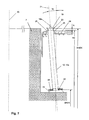
- FIG. 7 is a schematic cutaway view of a core element fully positioned and oriented in a formwork
- FIG. 8 is an alternative embodiment of a positioning aid.
- FIG. 1 shows a schematic cutaway view of a concrete foundation 1 according to the invention for a wind power tower 3 .
- the wind power tower 3 consists of many ring-shaped or ring segment-shaped precast concrete parts 4 arranged on top and fastened with one another as well as to the foundation 1 with tendons 2 .
- the tendons 2 run externally, i.e. outside of the concrete cross section of the precast concrete parts 4 .
- the invention is also suitable for wind power towers 3 whose tendons 2 run in tensioning channels inside the concrete cross section. All known tendons, especially tensioning wires, tensioning steels, tensioning chords or tensioning strands, can be considered as tendons 2 .
- the tendons 2 extend from the foundation 1 to a head section of the wind power tower 3 (not shown here) and can be pre-stressed with a tensioning device (not shown here as well).
- a tensioning device not shown here as well.
- the tendons 2 are guided through passage openings that extend between an upper side and underside of the foundation 1 and fixed in place on the underside of the foundation 1 .
- the concrete foundation has a recess 11 on the underside that forms an abutment for the tendons 2 fixed in place there.
- fastening positions 28 are provided, preferably distributed uniformly across the perimeter of the concrete foundation 1 (see also FIG. 6 b ).
- one core element 12 is now cast into the concrete foundation 1 in every one of the fastening positions 28 provided.
- the core elements 12 are oriented and positioned in the formwork in the fastening positions 28 provided for fastening the wind power tower 3 and, as a result of that, cast in the fastening positions 28 provided.
- the core elements 12 are hollow jacket pipes 12 a that remain in the concrete foundation 1 after the latter has been cast.
- formwork cores can be used as core elements 12 , which are removed from the concrete foundation 1 after it has been cast.
- jacket pipes 12 a have been cast in as one-part jacket pipes 12 a with a constant inner cross section.
- Such an exact casting in of the core elements 12 or jacket pipes 12 a is made possible by a very exact positioning device.
- the core elements 12 have been positioned with an accuracy of +/ ⁇ 1 mm in the formwork and afterwards cast with a correspondingly high accuracy of +/ ⁇ 1 mm into the concrete foundation 1 .
- FIGS. 5 a , 5 b and 6 a , 6 b show various steps in the manufacturing of the foundation 1 , each one in a schematic cutaway view ( FIGS. 5 a , 6 a ) and in a schematic top view ( FIGS. 5 b , 6 b ).
- a granular sub-base 5 is made first on the ground in the area where the installation is being planned.
- a bottom plate 29 for the foundation 1 can also be made if need be.
- a measurement reference system is built (see FIG. 5 b ), which contains as measurement reference points, for example, a center 30 of the planned installation and another reference point 31 , located radially far away from the center 30 .
- the reference 31 can, for example, mark the direction of a door axis of the future wind power station.
- the measurement reference system is now built with its calibration axes, thereby forming, for example, a height reference plane 32 of the measurement reference system through the upper edge of the granular sub-base 5 .
- a formwork bottom 8 (which in the example shown forms the subsequent recess 11 ) is first erected on the upper edge of the granular sub-base 5 .
- the formwork bottom 8 can be made in the usual way and braced on the granular sub-base 5 .
- the height positioning of the core elements 12 takes place not directly, but indirectly by arranging a positioning aid 13 that determines in each case the position of the core elements 12 (in this case jacket pipes 12 a ) with the help of an adapter device 16 . Since the positioning aids 13 should be later positioned merely by placing them down on the formwork bottom 8 exactly at their target height SHSB, an exact height-wise installation of the formwork bottom 8 is therefore necessary as well. For this reason, the formwork bottom 8 is exactly leveled on its prescribed target height SH by means of several measurement points 6 . According to the drawing shown in FIG.
- the formwork bottom 8 is made up of several segments 10 , which are individually installed height-wise by means of several measurement points 6 . In this case, merely four segments with just three measurement points are shown; however, depending on the size of the installation, considerably more segments 10 can also be provided. Likewise, depending on the size of the segments 10 , several measurement points 6 can also be provided. Since the formwork 8 determines the height position of the positioning aids 13 , the formwork bottom 8 has a large even surface.
- the formwork bottom 8 is oriented parallel to the reference plane 32 of the measurement system. As a result of that, the arrangement of the first positioning aid 13 on the formwork bottom 8 is facilitated. In principle, however, it is also possible to build the formwork bottom 8 with an inclination.
- FIGS. 6 a and 6 b show the provision of a positioning device with at least one first positioning aid 13 to orient the jacket pipes 12 a .
- a positioning device is provided with at least one first positioning aid 13 on the formwork bottom 8 installed heightwise for a subsequent fastening of the fastening positions 28 provided for the wind power tower 3 .
- one positioning aid 13 or one positioning device is provided for each fastening position 28 .
- a combination of tendons 2 with other types of fastening, such as anchors with anchor sleeves, is also conceivable.
- Each positioning aid 13 has one adapter device 16 for each core element 12 , so that if the positioning aid 13 is correctly oriented by connecting the core element (in this example, a jacket pipe 12 a ) with the adapter device 16 , at least one lower edge 22 of the core element 12 to be positioned is already exactly positioned at its target height SHUK.
- FIG. 2 shows a top view of a first positioning aid 13 of a position device according to the invention and FIG. 3 shows a cutaway view of the positioning aid 13 of FIG. 2 .
- the positioning aid 13 has the adapter device 16 , here formed by a projection protruding from the surface of the positioning aid ( FIG. 3 ).
- the cross section dimensions of the projection or adapter device 16 correspond here largely to those of the core element 12 provided, so that it can be connected to it by simple insertion in the adapter device 16 .
- This drawing shows an adapter device 16 for a rectangular or square jacket pipe 12 a .
- round jacket pipes 12 a or core elements 12 with the corresponding round adapter devices 16 can also be considered.
- the first positioning aid 13 has at least one reference segment 17 , in this case a seat 17 a for a measuring reflector 18 .
- the positioning aid 13 seen here has four seats 17 a for measuring reflectors 18 , as a result of which an especially accurate orientation of the positioning aid 13 in its target position can take place.
- the seats 17 a for the measuring reflectors can be formed by bore holes.
- the first positioning aid 13 still has fastening bore holes 27 , here four fastening bore holes 27 , with which the exactly oriented positioning aid 13 can be fixed in its target position.
- the positioning aid 13 contains advantageously a solid body 14 , in which the adapter device 16 and the at least one reference segment 17 have been incorporated as one single piece.
- the solid body 14 has a flat installation surface 15 , so that, after precise height-wise installation of the first formwork bottom 8 on its target height SHSB, the positioning aid 13 must only be placed on top of the formwork bottom 8 . As a result of that, it is already positioned automatically at its correct target height, which corresponds to the target height SHSB of the formwork bottom 8 .
- FIG. 8 shows a variation of a first positioning aid 13 , which also has an adapter device 16 for a core element 12 (as shown in FIG. 2 ), but here it contains merely one single seat 17 a for a measuring reflector 18 as reference segment 17 .
- the only seat 17 a found in the center makes it possible to already orient the positioning aid 13 correctly and thus the lower end of the core element 12 .
- the orientation of the adapter device 20 lies perpendicular to the lower installation surface 15 . Nonetheless, after placing the core element 12 on top of the adapter device 16 , the lower edge of the core element 12 is positioned with respect to its target height SHUK.
- the installation of the core element longitudinal axis 21 can take place by pivoting the core element 12 on the adapter device 20 .
- FIG. 6 b now shows the partially erected formwork 7 , in which a formwork wall 9 has already been mounted apart from the first formwork bottom 8 .
- a first positioning aid 13 has been placed on top of every one of the fastening positions 28 provided and already positioned in radial and angular target position SLR and SLW.
- a measuring reflector 18 (here a measuring sphere 18 a indicated by a dot-dash line) is now inserted in the first seat 17 a , the solid body 14 is installed by means of the target coordinates for the first seat 17 a and fixed in place with respect to its position.
- the target coordinates refer advantageously in each case to the center of a measuring sphere 18 a located in the seat 17 a .
- the measuring sphere 18 a is inserted in the second seat 17 a and the positioning aid 13 is installed and fixed in place on its target position using the target coordinates prescribed for the second seat 17 a.
- a total of four seats 17 a are provided for a measuring sphere 18 a , in which one measuring sphere 18 a is inserted and measured in succession.
- one set of target coordinates is prescribed for each one of the four seats 17 a . Since the solid bodies 14 are already at their target height SHSB, each set contains merely two target coordinates, which determine the radial position and angular position of the respective measurement body 18 .
- the measurements for the third and fourth seat 17 a serve merely for checking.
- the positioning aid 13 is calibrated fully also with regard to its angular target position SLW and radial target position SLR and installed, it is finally fixed to the first formwork bottom 8 by means of a fastening device.
- the fastening bore holes 27 are provided for it.
- Other fixing devices such as fixing parts, for example, which merely brace the external edges of the positioning device 13 , are also possible, however.
- the formwork wall 9 is finally mounted, as shown in FIG. 6 a .
- the core element 12 to be positioned can be arranged on the adapter device 16 with its lower end, inserted or placed on it, for example, so that the lower end of the core element 12 is already positioned in its target position with regard to angle and radius SLR and SLW and furthermore the bottom edge 22 is automatically also positioned at its target height SHUK (see also FIG. 7 ).
- the positioning device comprises a second positioning aid 19 .
- the orientation of the core element longitudinal axis 21 is shown schematically in a cutaway view in FIG. 7 and explained further below.
- the second positioning aid 19 is shown in a schematic cutaway view in FIG. 4 .
- the second positioning aid 19 also has an adapter device 20 for a core element 12 , which is also executed here as a projection of the positioning aid 19 and also executed as projection of the positioning aid 19 here.
- an adapter device 20 for a core element 12 which is also executed here as a projection of the positioning aid 19 and also executed as projection of the positioning aid 19 here.
- the cross section of the adapter device 20 corresponds largely to the cross section of the jacket pipe 12 a .
- a stop 33 lies next to the upper edge 23 of the jacket pipe 12 a .
- the second positioning aid 19 also has a reference segment 17 , here a seat 17 a , for a measuring reflector 18 that can be, for example, a measuring prism 18 b , which can be placed on top of the seat 17 a of the second positioning aid 19 .
- a measuring reflector 18 can be, for example, a measuring prism 18 b
- the positioning aid 19 could also have a recess as adapter device 20 , so that the positioning aid 19 would be pluggable with its recess over the core element 12 .
- FIG. 7 shows the setup of the core element longitudinal axis 21 .
- a reinforcement 24 shown here only partially for clarity reasons—is mounted on the formwork 7 .
- an anchor plate 26 is connected (e.g. welded) to the core element 12 already before the latter is plugged in. As a result of this, the plate is later cast on the correct place into the foundation 1 so a substantial force can be initiated in the foundation 1 .
- FIG. 1 shows core elements 12 executed as jacket pipes 12 a with the anchor plates 26 fastened to them in cast-in state.
- the core element longitudinal axis 21 is now set up to its angle W compared to the perpendicular by means of the measuring reflector 18 with the help of the target coordinates prescribed for this measuring reflector 18 , whereat owing to the angular position of the core element longitudinal axis 21 next to the radial target position SLR and the angular target position SLW of the measuring reflector 18 , its height must also be considered. Therefore, for a measuring reflector 18 located in the seat 17 a of the positioning aids 19 , one set of target coordinates consisting of three coordinates is prescribed in each case.
- the installation of the core element 12 takes place initially in a first direction and the core element is already fixed to the reinforcement 24 with respect to this first direction.
- fixation parts 25 are provided for this, placed on the outer edges of the core element 12 located in its target position and attached to the reinforcement (e.g. screwed, clamped or welded to it).
- the core element 12 can also be directly attached to the reinforcement (e.g. screwed, clamped or welded to it). If the core element 12 is made of steel, it can also be welded directly to the reinforcement 24 in its target position.
- the setup of the core element longitudinal axis 21 can take place with regard to its second direction perpendicular to the first one. After the core element longitudinal axis 21 has been fully oriented, the core element 12 can, in turn, be fixed to the reinforcement 24 by means of additional fixation parts 25 . Naturally, the fixation of the core elements 12 can also take place in this step in another way, as already described above.
- the angle W of the core element longitudinal axis 21 compared to the perpendicular is here up to 15°, preferably about 5°, the core element axis 21 being pivoted in the direction of the foundation center 30 or the foundation middle axis, as shown here, and the formwork bottom 8 is installed flat and parallel to the height reference plane 32 .
- the orientation of the adapter device 16 already corresponds exactly to the subsequent position of the core element longitudinal axis 21 with regard to its angle W (cf. FIG. 3 too).
- the height of the upper edge of the core elements 12 SHOK is metrologically recorded and then a maximum filling height FH of the formwork 7 is determined from it.
- a distance A of several centimeters between the maximum filling height FH and the target height of the upper edge of the core elements 12 SHOK is provided.
- the positioning aid 13 can be removed so that the anchor plate 26 now forms the lower edge of the foundation 1 in the fastening positions 28 , as can be seen in FIG. 1 , and can serve there for anchoring the tendons 2 .
- the location of the core elements 12 is measured and positioned by means of the method according to the invention and with the positioning aids according to the invention with an accuracy of +/ ⁇ 1 mm, so that core elements 12 can also be used now without funnel-shaped expansions in their ends. Due to the exact orientation of the core elements 12 , there are no deviations or only very slight ones between the subsequent course of the tendon axis and the course of the axis of the passage openings. Bending and close fitting of the tendons 2 against the walls of the passage openings or the jacket pipe 12 a can be largely prevented as a result of this, so that damages to the tendons 2 can no longer occur.
Landscapes
- Engineering & Computer Science (AREA)
- Life Sciences & Earth Sciences (AREA)
- General Engineering & Computer Science (AREA)
- Civil Engineering (AREA)
- Structural Engineering (AREA)
- Paleontology (AREA)
- General Life Sciences & Earth Sciences (AREA)
- Mining & Mineral Resources (AREA)
- Architecture (AREA)
- Mechanical Engineering (AREA)
- Sustainable Development (AREA)
- Sustainable Energy (AREA)
- Chemical & Material Sciences (AREA)
- Combustion & Propulsion (AREA)
- Hydrology & Water Resources (AREA)
- Environmental & Geological Engineering (AREA)
- Foundations (AREA)
- Manufacturing Of Tubular Articles Or Embedded Moulded Articles (AREA)
- Bridges Or Land Bridges (AREA)
- Wind Motors (AREA)
- Forms Removed On Construction Sites Or Auxiliary Members Thereof (AREA)
Applications Claiming Priority (4)
| Application Number | Priority Date | Filing Date | Title |
|---|---|---|---|
| DE102013105512.5 | 2013-05-29 | ||
| DE102013105512.5A DE102013105512A1 (de) | 2013-05-29 | 2013-05-29 | Betonfundament und Verfahren zur Herstellung eines Betonfundaments für einen Windkraftturm sowie Positioniervorrichtung zur Positionierung von Hüllrohren in einem Betonfundament |
| DE102013105512 | 2013-05-29 | ||
| PCT/EP2014/001440 WO2014191102A2 (fr) | 2013-05-29 | 2014-05-28 | Fondation en béton et procédé de fabrication d'une fondation en béton pour une tour d'éolienne ainsi que dispositif de positionnement de gaines dans une fondation en béton |
Publications (2)
| Publication Number | Publication Date |
|---|---|
| US20160108600A1 US20160108600A1 (en) | 2016-04-21 |
| US10443205B2 true US10443205B2 (en) | 2019-10-15 |
Family
ID=51211718
Family Applications (1)
| Application Number | Title | Priority Date | Filing Date |
|---|---|---|---|
| US14/893,612 Expired - Fee Related US10443205B2 (en) | 2013-05-29 | 2014-05-28 | Concrete foundation, method for producing a concrete foundation for a wind power tower, and positioning device for positioning jacket pipes in a concrete foundation |
Country Status (10)
| Country | Link |
|---|---|
| US (1) | US10443205B2 (fr) |
| EP (1) | EP3004467B1 (fr) |
| CN (1) | CN105431595B (fr) |
| BR (1) | BR112015029316A2 (fr) |
| CA (1) | CA2913594A1 (fr) |
| DE (1) | DE102013105512A1 (fr) |
| DK (1) | DK3004467T3 (fr) |
| ES (1) | ES2658415T3 (fr) |
| PL (1) | PL3004467T3 (fr) |
| WO (1) | WO2014191102A2 (fr) |
Cited By (4)
| Publication number | Priority date | Publication date | Assignee | Title |
|---|---|---|---|---|
| US10941536B2 (en) * | 2016-10-24 | 2021-03-09 | Acciona Windpower, S.A. | Wind turbine foundation |
| US11168457B2 (en) * | 2017-08-01 | 2021-11-09 | Maxbögl Wind Ag | Foundation for a structure |
| US11773650B2 (en) | 2017-10-20 | 2023-10-03 | Max Bögl Wind AG | Method for erecting a tower, tower segment, supply structure, and tower |
| US12071780B2 (en) | 2018-03-07 | 2024-08-27 | Max Gögl Wind Ag | Method for introducing prestressed elements into a tower, assembly device, unwinding device and adapter device |
Families Citing this family (11)
| Publication number | Priority date | Publication date | Assignee | Title |
|---|---|---|---|---|
| US8734705B2 (en) * | 2008-06-13 | 2014-05-27 | Tindall Corporation | Method for fabrication of structures used in construction of tower base supports |
| DE102013105512A1 (de) * | 2013-05-29 | 2014-12-04 | Max Bögl Wind AG | Betonfundament und Verfahren zur Herstellung eines Betonfundaments für einen Windkraftturm sowie Positioniervorrichtung zur Positionierung von Hüllrohren in einem Betonfundament |
| DE102013226536A1 (de) * | 2013-12-18 | 2015-06-18 | Wobben Properties Gmbh | Anordnung mit einem Betonfundament und einem Turm und Verfahren zum Errichten eines Turms |
| MX2017008938A (es) * | 2015-01-09 | 2018-05-17 | Tindall Corp | Torre y metodo para construir una torre. |
| CN104690516A (zh) * | 2015-03-20 | 2015-06-10 | 柳州市友健机械有限公司 | 一种扁型锚垫板的加工方法 |
| BE1024818B1 (nl) * | 2015-10-28 | 2018-07-06 | Design By Reduction Bvba | Bekisting voor het vervaardigen van een betonnen constructie, bekistingssysteem ter vorming van zulke bekisting en werkwijze voor het vervaardigen van een betonnen constructie |
| AT519190A1 (de) * | 2016-09-26 | 2018-04-15 | Holcim Technology Ltd | Fundament für eine Windmühle |
| ES2811504T3 (es) * | 2018-02-05 | 2021-03-12 | Metalvix Engenharia E Consultoria Ltda | Torre de turbina eólica y base de cimentación respectiva |
| PL3781747T3 (pl) * | 2018-04-16 | 2025-02-10 | Smart & Green Mukran Concrete Gmbh | Sposób wytwarzania fundamentu turbiny wiatrowej |
| CN109323689B (zh) * | 2018-12-03 | 2023-10-03 | 中铁六局集团有限公司 | 全站仪测量辅助装置和全站仪测量系统 |
| CN113090097B (zh) * | 2021-03-30 | 2024-03-12 | 湖南省永盛电力器材有限公司 | 一种信号塔用输电线路铁塔部件 |
Citations (32)
| Publication number | Priority date | Publication date | Assignee | Title |
|---|---|---|---|---|
| US2374624A (en) * | 1942-02-24 | 1945-04-24 | Ethel F Schwendt | Precast foundation |
| US4406094A (en) * | 1980-02-28 | 1983-09-27 | Messerschmitt-Boelkow-Blohm Gesellschaft Mit Beschraenkter Haftung | Apparatus for anchoring self-supporting, tall structures |
| US5379563A (en) * | 1993-09-13 | 1995-01-10 | Eastman Chemical Company | Anchoring assembly |
| US5826387A (en) * | 1994-11-23 | 1998-10-27 | Henderson; Allan P. | Pier foundation under high unit compression |
| DE10126912A1 (de) | 2001-06-01 | 2002-12-19 | Oevermann Gmbh & Co Kg Hoch Un | Turmbauwerk aus Spannbeton |
| US6665990B1 (en) * | 2000-03-06 | 2003-12-23 | Barr Engineering Co. | High-tension high-compression foundation for tower structures |
| AU2002362779B2 (en) | 2001-10-09 | 2005-10-13 | Aloys Wobben | Method for establishing a foundation in particular for a tower of a wind energy plant |
| US20060048471A1 (en) * | 2004-09-06 | 2006-03-09 | Research Institute Of Industrial Science & Technology | Strengthening device to increase strength of grout layer |
| US20070107339A1 (en) | 2003-06-16 | 2007-05-17 | Takashi Matsumoto | Method of accurately positioning anchor bolt to foundation by swing-type anchor bolt |
| US20090000227A1 (en) * | 2007-06-28 | 2009-01-01 | Nordex Energy Gmbh | Wind energy plant tower |
| CN101634153A (zh) | 2009-07-17 | 2010-01-27 | 中冶实久建设有限公司 | 一种设备基础内竖向埋管安装找正定位的方法 |
| DE202009013844U1 (de) | 2009-10-12 | 2010-02-18 | Heijmans Oevermann Gmbh | Betonfundament für einen Stahlturm |
| CN201459553U (zh) | 2009-06-30 | 2010-05-12 | 上海磁浮交通发展有限公司 | 轨道梁预检工装结构 |
| DE20122941U1 (de) | 2000-07-12 | 2011-02-24 | Wobben, Aloys | Turm aus Spannbeton-Fertigteilen |
| US20110126481A1 (en) * | 2009-12-01 | 2011-06-02 | Henrik Stiesdal | Concrete tower |
| US8051627B2 (en) * | 2006-04-30 | 2011-11-08 | General Electric Company | Tower adapter, method of producing a tower foundation and tower foundation |
| CN202493386U (zh) | 2012-02-22 | 2012-10-17 | 阜新金胤新能源技术咨询有限公司 | 体外预应力钢-混凝土风电塔架 |
| US20120266552A1 (en) * | 2009-12-23 | 2012-10-25 | Alain Huynh Tong | Tower having a pre-stressed concrete column and construction method |
| US20120272614A1 (en) | 2009-10-30 | 2012-11-01 | Norman Perner | Tidal Power Plant and Method for the Creation Thereof |
| CN102767303A (zh) | 2012-07-13 | 2012-11-07 | 北京金风科创风电设备有限公司 | 一种预制混凝土塔架及其构建方法 |
| US20120311948A1 (en) * | 2010-02-01 | 2012-12-13 | Conelto Aps | Tower Construction and a Method for Erecting the Tower Construction |
| US20130081350A1 (en) * | 2010-06-14 | 2013-04-04 | Max Bogi Bauunternehmung Gmbh & Co. Kg | Tower Comprising an Adapter Piece and Method for Producing a Tower Comprising an Adapter Piece |
| US20130125480A1 (en) * | 2011-11-17 | 2013-05-23 | Acciona Windpower, S.A. | Process and Unit for the Attachment of a Wind Turbine's Tower to a Foundation and Wind Turbine Incorporating Said Unit |
| US20130212963A1 (en) * | 2012-02-21 | 2013-08-22 | Fabcon, Inc. | Wind Turbine Tower |
| US20140250806A1 (en) * | 2013-03-05 | 2014-09-11 | Karsten Schibsbye | Wind turbine tower arrangement |
| US8898991B2 (en) * | 2012-09-07 | 2014-12-02 | General Electric Company | Wind turbine tower base assembly with detachable tower base rings |
| US20150143765A1 (en) * | 2012-02-28 | 2015-05-28 | Ms Enertech, S.L. | Connection between a wind turbine tower and its foundation |
| US20150247335A1 (en) * | 2012-10-01 | 2015-09-03 | Gestamp Hybrid Towers, S.L. | Support structure for wind-driven power generators and mold for obtaining such structures |
| US20150376859A1 (en) * | 2006-09-21 | 2015-12-31 | Ahmed Phuly | Fatigue Resistant Foundation |
| US20160108600A1 (en) * | 2013-05-29 | 2016-04-21 | Max Bögl Wind AG | Concrete Foundation, Method for Producing a Concrete Foundation for a Wind Power Tower, and Positioning Device for Positioning Jacket Pipes in a Concrete Foundation |
| US9322396B2 (en) * | 2011-11-08 | 2016-04-26 | Wobben Properties Gmbh | Foundation for a wind turbine |
| US20170190391A1 (en) * | 2014-07-01 | 2017-07-06 | Aerodyn Engineering Gmbh | Floating Wind Turbine with a Floating Foundation, and Method for Installation of Such a Wind Turbine |
Family Cites Families (2)
| Publication number | Priority date | Publication date | Assignee | Title |
|---|---|---|---|---|
| DE19981698D2 (de) | 1998-09-09 | 2001-08-09 | Bilfinger Berger Bau | Vorrichtung zur externen Vorspannung von Bauwerken |
| CN202066477U (zh) * | 2010-12-30 | 2011-12-07 | 二重集团(德阳)重型装备股份有限公司 | 法兰定位用激光测量靶座 |
-
2013
- 2013-05-29 DE DE102013105512.5A patent/DE102013105512A1/de not_active Withdrawn
-
2014
- 2014-05-28 CN CN201480030848.7A patent/CN105431595B/zh not_active Expired - Fee Related
- 2014-05-28 CA CA2913594A patent/CA2913594A1/fr not_active Abandoned
- 2014-05-28 US US14/893,612 patent/US10443205B2/en not_active Expired - Fee Related
- 2014-05-28 ES ES14741515.2T patent/ES2658415T3/es active Active
- 2014-05-28 EP EP14741515.2A patent/EP3004467B1/fr active Active
- 2014-05-28 PL PL14741515T patent/PL3004467T3/pl unknown
- 2014-05-28 DK DK14741515.2T patent/DK3004467T3/en active
- 2014-05-28 WO PCT/EP2014/001440 patent/WO2014191102A2/fr not_active Ceased
- 2014-05-28 BR BR112015029316A patent/BR112015029316A2/pt not_active IP Right Cessation
Patent Citations (33)
| Publication number | Priority date | Publication date | Assignee | Title |
|---|---|---|---|---|
| US2374624A (en) * | 1942-02-24 | 1945-04-24 | Ethel F Schwendt | Precast foundation |
| US4406094A (en) * | 1980-02-28 | 1983-09-27 | Messerschmitt-Boelkow-Blohm Gesellschaft Mit Beschraenkter Haftung | Apparatus for anchoring self-supporting, tall structures |
| US5379563A (en) * | 1993-09-13 | 1995-01-10 | Eastman Chemical Company | Anchoring assembly |
| US5826387A (en) * | 1994-11-23 | 1998-10-27 | Henderson; Allan P. | Pier foundation under high unit compression |
| US6665990B1 (en) * | 2000-03-06 | 2003-12-23 | Barr Engineering Co. | High-tension high-compression foundation for tower structures |
| DE20122941U1 (de) | 2000-07-12 | 2011-02-24 | Wobben, Aloys | Turm aus Spannbeton-Fertigteilen |
| DE10126912A1 (de) | 2001-06-01 | 2002-12-19 | Oevermann Gmbh & Co Kg Hoch Un | Turmbauwerk aus Spannbeton |
| AU2002362779B2 (en) | 2001-10-09 | 2005-10-13 | Aloys Wobben | Method for establishing a foundation in particular for a tower of a wind energy plant |
| US20070107339A1 (en) | 2003-06-16 | 2007-05-17 | Takashi Matsumoto | Method of accurately positioning anchor bolt to foundation by swing-type anchor bolt |
| US20060048471A1 (en) * | 2004-09-06 | 2006-03-09 | Research Institute Of Industrial Science & Technology | Strengthening device to increase strength of grout layer |
| US8051627B2 (en) * | 2006-04-30 | 2011-11-08 | General Electric Company | Tower adapter, method of producing a tower foundation and tower foundation |
| US20150376859A1 (en) * | 2006-09-21 | 2015-12-31 | Ahmed Phuly | Fatigue Resistant Foundation |
| US20090000227A1 (en) * | 2007-06-28 | 2009-01-01 | Nordex Energy Gmbh | Wind energy plant tower |
| CN201459553U (zh) | 2009-06-30 | 2010-05-12 | 上海磁浮交通发展有限公司 | 轨道梁预检工装结构 |
| CN101634153A (zh) | 2009-07-17 | 2010-01-27 | 中冶实久建设有限公司 | 一种设备基础内竖向埋管安装找正定位的方法 |
| DE202009013844U1 (de) | 2009-10-12 | 2010-02-18 | Heijmans Oevermann Gmbh | Betonfundament für einen Stahlturm |
| US20120272614A1 (en) | 2009-10-30 | 2012-11-01 | Norman Perner | Tidal Power Plant and Method for the Creation Thereof |
| US20110126481A1 (en) * | 2009-12-01 | 2011-06-02 | Henrik Stiesdal | Concrete tower |
| US20120266552A1 (en) * | 2009-12-23 | 2012-10-25 | Alain Huynh Tong | Tower having a pre-stressed concrete column and construction method |
| US20120311948A1 (en) * | 2010-02-01 | 2012-12-13 | Conelto Aps | Tower Construction and a Method for Erecting the Tower Construction |
| US20130081350A1 (en) * | 2010-06-14 | 2013-04-04 | Max Bogi Bauunternehmung Gmbh & Co. Kg | Tower Comprising an Adapter Piece and Method for Producing a Tower Comprising an Adapter Piece |
| US9322396B2 (en) * | 2011-11-08 | 2016-04-26 | Wobben Properties Gmbh | Foundation for a wind turbine |
| US20130125480A1 (en) * | 2011-11-17 | 2013-05-23 | Acciona Windpower, S.A. | Process and Unit for the Attachment of a Wind Turbine's Tower to a Foundation and Wind Turbine Incorporating Said Unit |
| US20130212963A1 (en) * | 2012-02-21 | 2013-08-22 | Fabcon, Inc. | Wind Turbine Tower |
| CN202493386U (zh) | 2012-02-22 | 2012-10-17 | 阜新金胤新能源技术咨询有限公司 | 体外预应力钢-混凝土风电塔架 |
| US20150143765A1 (en) * | 2012-02-28 | 2015-05-28 | Ms Enertech, S.L. | Connection between a wind turbine tower and its foundation |
| CN102767303A (zh) | 2012-07-13 | 2012-11-07 | 北京金风科创风电设备有限公司 | 一种预制混凝土塔架及其构建方法 |
| US8898991B2 (en) * | 2012-09-07 | 2014-12-02 | General Electric Company | Wind turbine tower base assembly with detachable tower base rings |
| US20150247335A1 (en) * | 2012-10-01 | 2015-09-03 | Gestamp Hybrid Towers, S.L. | Support structure for wind-driven power generators and mold for obtaining such structures |
| US9234364B2 (en) * | 2012-10-01 | 2016-01-12 | Gestamp Hybrid Towers, S.L. | Support structure for wind-driven power generators and mold for obtaining such structures |
| US20140250806A1 (en) * | 2013-03-05 | 2014-09-11 | Karsten Schibsbye | Wind turbine tower arrangement |
| US20160108600A1 (en) * | 2013-05-29 | 2016-04-21 | Max Bögl Wind AG | Concrete Foundation, Method for Producing a Concrete Foundation for a Wind Power Tower, and Positioning Device for Positioning Jacket Pipes in a Concrete Foundation |
| US20170190391A1 (en) * | 2014-07-01 | 2017-07-06 | Aerodyn Engineering Gmbh | Floating Wind Turbine with a Floating Foundation, and Method for Installation of Such a Wind Turbine |
Non-Patent Citations (3)
| Title |
|---|
| English Translation of Chinese Office Action for Application No. 201480030848.7, dated Oct. 10, 2016. |
| Intellectual Property India, Examination Report dated Aug. 13, 2019 with translation therof. |
| International Search Report for International Application No. PCT/2014/001440, dated Mar. 12, 2014. |
Cited By (4)
| Publication number | Priority date | Publication date | Assignee | Title |
|---|---|---|---|---|
| US10941536B2 (en) * | 2016-10-24 | 2021-03-09 | Acciona Windpower, S.A. | Wind turbine foundation |
| US11168457B2 (en) * | 2017-08-01 | 2021-11-09 | Maxbögl Wind Ag | Foundation for a structure |
| US11773650B2 (en) | 2017-10-20 | 2023-10-03 | Max Bögl Wind AG | Method for erecting a tower, tower segment, supply structure, and tower |
| US12071780B2 (en) | 2018-03-07 | 2024-08-27 | Max Gögl Wind Ag | Method for introducing prestressed elements into a tower, assembly device, unwinding device and adapter device |
Also Published As
| Publication number | Publication date |
|---|---|
| CN105431595A (zh) | 2016-03-23 |
| WO2014191102A2 (fr) | 2014-12-04 |
| EP3004467A2 (fr) | 2016-04-13 |
| ES2658415T3 (es) | 2018-03-09 |
| WO2014191102A3 (fr) | 2015-01-22 |
| CA2913594A1 (fr) | 2014-12-04 |
| US20160108600A1 (en) | 2016-04-21 |
| DE102013105512A1 (de) | 2014-12-04 |
| BR112015029316A2 (pt) | 2017-07-25 |
| DK3004467T3 (en) | 2018-02-12 |
| EP3004467B1 (fr) | 2017-12-06 |
| CN105431595B (zh) | 2018-01-26 |
| PL3004467T3 (pl) | 2018-04-30 |
Similar Documents
| Publication | Publication Date | Title |
|---|---|---|
| US10443205B2 (en) | Concrete foundation, method for producing a concrete foundation for a wind power tower, and positioning device for positioning jacket pipes in a concrete foundation | |
| DK2580409T3 (en) | TOWER FOR A WIND ENERGY INSTALLATION AND PROCEDURE FOR THE PREPARATION OF A TOWER FOR A WIND ENERGY INSTALLATION | |
| ES2949992T3 (es) | Cimentación para un aerogenerador | |
| CN103590510B (zh) | 装配式结构与现浇结构中预埋钢筋的固定连接方法 | |
| CN103930623A (zh) | 风能设备的基座 | |
| KR20150051503A (ko) | 프리캐스트 교각의 조정단 구조 및 이를 이용한 프리캐스트 교각의 시공방법 | |
| CN109853610A (zh) | 钢管柱混凝土基础预埋地脚螺栓精准定位机构及定位方法 | |
| JP2012140848A (ja) | 据え付け基礎施工方法 | |
| KR101421212B1 (ko) | 파워 모노레일의 기초 구조물 | |
| CN110847464B (zh) | 确保现浇结构顶板水平度的施工和测量方法 | |
| KR20140115512A (ko) | 콘크리트 케이지를 포함하는 연결구조체 및 이를 구비하는 강관말뚝과 강재기둥의 연결부의 휨강도를 보강하는 시공방법 | |
| CN119122303A (zh) | 预埋锚栓施工方法 | |
| CN112144873A (zh) | 一种圆形轨道螺栓预埋方法 | |
| CN109930628A (zh) | 一种预埋哈芬槽的安装装置及方法 | |
| KR20200053874A (ko) | 원심 성형 중공 사각 pc 기둥 및 이의 제조 방법 | |
| CN110536992A (zh) | 生产假共轭预制混凝土组件的方法 | |
| CN116927143B (zh) | 带靠船构件的单桩桩帽的模板及其施工方法 | |
| CN222613967U (zh) | 一种钢筋定位工装 | |
| JP2019007345A (ja) | 既製杭 | |
| EA021900B1 (ru) | Способ изготовления сборных элементов сооружений | |
| CN121803053A (zh) | 一种短柱模板安装与预埋锚栓同步定位施工方法 | |
| RU2782015C2 (ru) | Фундамент для ветроэнергетической установки | |
| JP7018869B2 (ja) | 固定具 | |
| CN121473591A (zh) | 一种基于三维扫描的大跨度钢结构桁架施工方法 | |
| CN120575666A (zh) | 一种适用于带吊车梁牛腿的超高框架混凝土结构施工工法 |
Legal Events
| Date | Code | Title | Description |
|---|---|---|---|
| AS | Assignment |
Owner name: MAX BOEGL WIND AG, GERMANY Free format text: ASSIGNMENT OF ASSIGNORS INTEREST;ASSIGNOR:MENZEL, JUERGEN;REEL/FRAME:038878/0751 Effective date: 20160125 |
|
| STPP | Information on status: patent application and granting procedure in general |
Free format text: FINAL REJECTION MAILED |
|
| STPP | Information on status: patent application and granting procedure in general |
Free format text: ADVISORY ACTION MAILED |
|
| STPP | Information on status: patent application and granting procedure in general |
Free format text: NOTICE OF ALLOWANCE MAILED -- APPLICATION RECEIVED IN OFFICE OF PUBLICATIONS |
|
| STPP | Information on status: patent application and granting procedure in general |
Free format text: PUBLICATIONS -- ISSUE FEE PAYMENT VERIFIED |
|
| STPP | Information on status: patent application and granting procedure in general |
Free format text: WITHDRAW FROM ISSUE AWAITING ACTION |
|
| STCF | Information on status: patent grant |
Free format text: PATENTED CASE |
|
| FEPP | Fee payment procedure |
Free format text: MAINTENANCE FEE REMINDER MAILED (ORIGINAL EVENT CODE: REM.); ENTITY STATUS OF PATENT OWNER: LARGE ENTITY |
|
| LAPS | Lapse for failure to pay maintenance fees |
Free format text: PATENT EXPIRED FOR FAILURE TO PAY MAINTENANCE FEES (ORIGINAL EVENT CODE: EXP.); ENTITY STATUS OF PATENT OWNER: LARGE ENTITY |
|
| STCH | Information on status: patent discontinuation |
Free format text: PATENT EXPIRED DUE TO NONPAYMENT OF MAINTENANCE FEES UNDER 37 CFR 1.362 |
|
| FP | Lapsed due to failure to pay maintenance fee |
Effective date: 20231015 |