US10465347B2 - Method for working ground pavements, as well as self-propelled construction machine - Google Patents
Method for working ground pavements, as well as self-propelled construction machine Download PDFInfo
- Publication number
- US10465347B2 US10465347B2 US15/679,349 US201715679349A US10465347B2 US 10465347 B2 US10465347 B2 US 10465347B2 US 201715679349 A US201715679349 A US 201715679349A US 10465347 B2 US10465347 B2 US 10465347B2
- Authority
- US
- United States
- Prior art keywords
- construction machine
- milling drum
- working operation
- operating parameter
- interruption
- Prior art date
- Legal status (The legal status is an assumption and is not a legal conclusion. Google has not performed a legal analysis and makes no representation as to the accuracy of the status listed.)
- Active
Links
Images


Classifications
-
- E—FIXED CONSTRUCTIONS
- E01—CONSTRUCTION OF ROADS, RAILWAYS, OR BRIDGES
- E01C—CONSTRUCTION OF, OR SURFACES FOR, ROADS, SPORTS GROUNDS, OR THE LIKE; MACHINES OR AUXILIARY TOOLS FOR CONSTRUCTION OR REPAIR
- E01C23/00—Auxiliary devices or arrangements for constructing, repairing, reconditioning, or taking-up road or like surfaces
- E01C23/06—Devices or arrangements for working the finished surface; Devices for repairing or reconditioning the surface of damaged paving; Recycling in place or on the road
- E01C23/08—Devices or arrangements for working the finished surface; Devices for repairing or reconditioning the surface of damaged paving; Recycling in place or on the road for roughening or patterning; for removing the surface down to a predetermined depth high spots or material bonded to the surface, e.g. markings; for maintaining earth roads, clay courts or like surfaces by means of surface working tools, e.g. scarifiers, levelling blades
- E01C23/085—Devices or arrangements for working the finished surface; Devices for repairing or reconditioning the surface of damaged paving; Recycling in place or on the road for roughening or patterning; for removing the surface down to a predetermined depth high spots or material bonded to the surface, e.g. markings; for maintaining earth roads, clay courts or like surfaces by means of surface working tools, e.g. scarifiers, levelling blades using power-driven tools, e.g. vibratory tools
- E01C23/088—Rotary tools, e.g. milling drums
-
- E—FIXED CONSTRUCTIONS
- E01—CONSTRUCTION OF ROADS, RAILWAYS, OR BRIDGES
- E01C—CONSTRUCTION OF, OR SURFACES FOR, ROADS, SPORTS GROUNDS, OR THE LIKE; MACHINES OR AUXILIARY TOOLS FOR CONSTRUCTION OR REPAIR
- E01C23/00—Auxiliary devices or arrangements for constructing, repairing, reconditioning, or taking-up road or like surfaces
- E01C23/06—Devices or arrangements for working the finished surface; Devices for repairing or reconditioning the surface of damaged paving; Recycling in place or on the road
- E01C23/12—Devices or arrangements for working the finished surface; Devices for repairing or reconditioning the surface of damaged paving; Recycling in place or on the road for taking-up, tearing-up, or full-depth breaking-up paving, e.g. sett extractor
- E01C23/122—Devices or arrangements for working the finished surface; Devices for repairing or reconditioning the surface of damaged paving; Recycling in place or on the road for taking-up, tearing-up, or full-depth breaking-up paving, e.g. sett extractor with power-driven tools, e.g. oscillated hammer apparatus
- E01C23/127—Devices or arrangements for working the finished surface; Devices for repairing or reconditioning the surface of damaged paving; Recycling in place or on the road for taking-up, tearing-up, or full-depth breaking-up paving, e.g. sett extractor with power-driven tools, e.g. oscillated hammer apparatus rotary, e.g. rotary hammers
-
- E—FIXED CONSTRUCTIONS
- E01—CONSTRUCTION OF ROADS, RAILWAYS, OR BRIDGES
- E01C—CONSTRUCTION OF, OR SURFACES FOR, ROADS, SPORTS GROUNDS, OR THE LIKE; MACHINES OR AUXILIARY TOOLS FOR CONSTRUCTION OR REPAIR
- E01C2301/00—Machine characteristics, parts or accessories not otherwise provided for
Definitions
- the invention relates to a method for working ground pavements, as well as to a self-propelled construction machine, specifically a road milling machine, soil stabilizer, recycler or surface miner.
- Self-propelled construction machines for working ground pavements are known, for example, from DE 10 2006 024 123 B4.
- the self-propelled construction machine described therein comprises a machine frame, as well as a height-adjustable milling drum for working a ground pavement.
- the milling drum is driven by a drive unit.
- Such construction machine comprises a control device for monitoring and controlling the milling depth of the milling drum and the speed of the construction machine.
- the drive unit drives the milling drum via a power transmission drive, and the drive of the milling drum can be shifted via a, for example, mechanical coupling.
- milling drum may, however, also be specified for the milling drum to be driven by means of hydraulic motors or electric motors.
- the invention advantageously specifies for an interruption of the working operation to be detected, and for the drive of the milling drum to be interrupted in the event of a detected interruption of the working operation.
- the present invention offers the advantage that the milling drum is not driven when the same is not in working operation, and the energy consumption of the construction machine is consequently reduced.
- the milling drum is in working operation when the construction machine is working the ground, that is, when the construction machine is moving forward and the milling drum is rotating and is engaged with the ground.
- At least one operating parameter of the construction machine can be monitored.
- the at least one operating parameter of the construction machine which can be monitored to detect the interruption of the working operation may specifically be an actual operating parameter of the construction machine.
- An actual operating parameter is an operating parameter which reflects the current condition of the construction machine.
- the operating parameters which indicate as to whether the construction machine is stationary and/or the milling drum is engaged with the ground pavement are of particular relevance.
- the at least one operating parameter When detecting the interruption of the working operation, the at least one operating parameter, specifically the at least one actual operating parameter, may be compared with at least one specified limit value.
- the at least one operating parameter which can be monitored to detect the interruption of the working operation may be the actual milling depth and/or the actual speed.
- the actual milling depth can be used to monitor as to whether the milling drum is engaged with the ground pavement.
- the actual milling depth shows a positive value when the milling drum is engaged with the ground pavement, and when the milling drum is raised and therefore exhibits a distance to the ground pavement, the milling depth shows a negative amount.
- an interruption of the working operation can be detected when the actual speed of the construction machine is zero. This means that the working operation is interrupted when the construction machine is stationary.
- the speed input device of the construction machine and/or the movement of the travelling devices and/or the hydraulic pressure of the running gear motors driving the travelling devices can be monitored in order to monitor the actual speed of the construction machine.
- the construction machine comprises travelling devices by means of which the construction machine can travel over the ground pavement.
- the travelling devices may be wheels or tracked ground-engaging units which are connected to the machine frame via lifting columns.
- the travelling devices are preferably driven via hydraulic motors.
- the actual speed of the construction machine can be monitored by monitoring the nominal speed at the speed input device. Provided that the nominal speed of the construction machine is zero, the actual speed is typically also zero since the construction machine does not comprise a rolling operation so that the construction machine comes to a standstill immediately as soon as the nominal speed is zero.
- the milling drum When interrupting the drive of the milling drum, the milling drum may be decoupled from the drive unit, and/or the drive unit may be switched off in case of an electric or hydraulic drive unit.
- the interruption of the working operation of the milling drum may take place only after a specified time delay.
- the milling drum After the drive of the milling drum has been interrupted, it can be detected as to whether the working operation is to be continued, in which case, when detecting the intended continuation of the working operation, the milling drum is driven again.
- At least one operating parameter of the construction machine can be monitored.
- the at least one operating parameter which is monitored to detect the intended continuation of the working operation may specifically be a nominal operating parameter of the construction machine.
- a nominal operating parameter is an operating parameter which reflects a condition of the construction machine preadjusted by the operator.
- the operating parameter which is monitored to detect the intended continuation of the working operation may particularly preferably be the nominal speed of the construction machine and/or the nominal milling depth and/or the actual milling depth.
- An intended continuation of the working operation can be detected when the nominal speed of the construction machine is greater than zero, no reversing operation is detected, and the nominal milling depth exceeds a specified limit value.
- the limit value for the nominal milling depth may, for example, be zero.
- the limit value must be selected so as to ensure that a detection of the intended continuation of the working operation is effected when a nominal milling depth is adjusted at which the milling drum, when the same reaches the nominal milling depth, is able to engage with the ground. A certain degree of safety may be taken into account in this process when selecting the limit value.
- the movement of the construction machine and/or a lowering of the milling drum can be delayed for such a period of time that the milling drum has reached a specified operating speed of revolution. In this way, it is ensured that the milling drum has reached an operating speed of revolution when contact is made between the milling drum and the ground pavement.
- either the speed of revolution of the milling drum can be detected directly via, for example, a sensor, or the resumption of the milling operation can be delayed for a certain period of time after the milling drum is driven again in order to ensure that the milling drum has reached the operating speed of revolution again.
- the milling drum may be raised by a specified amount, in particular if the interruption of the working operation is effected because the actual speed is zero. This also ensures that, when the milling drum is driven again, the milling drum is not in contact with the ground pavement until the milling drum has reached an operating speed of revolution.
- the milling drum can be driven again and then lowered.
- a visual or audible signal may indicate that the milling operation was interrupted automatically. In this way, it is ensured that the operator and/or personnel in the environment of the construction machine are aware at any time that the milling drum can be switched on automatically when the working operation is to be continued.
- a defined position or a position range
- the machine frame is raised to the maximum height via the lifting columns, parts of the milling drum may be exposed which may lead to any material present in the milling drum casing being hurled out of the same if the milling drum is driven at that moment.
- a defined milling depth may therefore be adjusted automatically, for example, at which the milling drum does not yet engage with the ground pavement but an escape of material from the milling drum housing is excluded.
- the power output of the drive unit for example, the speed of revolution of a motor used as a drive unit, may be reduced following the interruption of the drive of the milling drum. It is increased again accordingly prior to driving the milling drum again.
- the milling drum Following the interruption of the drive of the milling drum, it may be specified for the same to continue rotating due to inertia. Alternatively, it may also be specified for it being braked, for example, in order to recover the energy of rotation for an energy storage device. The energy could be stored and then utilized when the milling drum is switched on again.
- the automated process of detecting the interruption of the working operation, interrupting the drive of the milling drum, detecting the continuation of the working operation and driving the milling drum again can be activated/deactivated by the operator.
- a self-propelled construction machine for working ground pavements comprising
- the self-propelled construction machine may also comprise travelling devices, where the travelling devices may comprise wheels or tracked ground-engaging units which may be connected to the machine frame in a height-adjustable fashion via lifting columns.
- the height adjustment of the lifting columns may be effected, for example, via hydraulic piston-cylinder units.
- the drive unit may specifically be a drive motor.
- the self-propelled construction machine may comprise one or multiple operating devices which comprise no less than one speed input device and one milling depth input device.
- the milling drum may be accommodated in a milling drum housing.
- the milling drum housing may comprise a left and a right edge protector at the end sides, a hold-down device at the front side and a scraper at the rear side, where the same close the working chamber of the milling drum towards the outside.
- the construction machine may also comprise front and rear drum plates to seal off the working chamber.
- the milling drum may be mounted in the machine frame.
- the milling drum may be directly connected to the machine frame. Regulation of the milling depth can then be effected by means of a height adjustment of the lifting columns which connect the ground-engaging units of the construction machine with the machine frame.
- the milling drum may be adjustable in height relative to the machine frame.
- the feature according to which the monitoring device detects the interruption of the working operation, and when detecting the interruption emits a signal to interrupt the drive of the milling drum, may be an additional feature which may be capable of being switched on or switched off.
- the monitoring device can monitor at least one operating parameter of the construction machine to detect the interruption of the working operation.
- the at least one operating parameter of the construction machine which is monitored to detect the interruption of the working operation may be an actual operating parameter, specifically the actual speed of the construction machine and/or the actual milling depth.
- the monitoring device may query the at least one operating parameter of the construction machine from the control device and/or from sensors and compare the at least one operating parameter queried with at least one specified limit value.
- the at least one specified limit value may be stored in the monitoring device.
- the at least one specified limit value may be determined by means of tests.
- the monitoring device may detect an interruption of the working operation and emit a signal to interrupt the drive of the milling drum when the actual speed of the construction machine is zero.
- the construction machine may comprise a power transmission device for transmitting a driving power from a drive unit to the milling drum.
- the monitoring device can emit the signal to interrupt the drive of the milling drum to the power transmission device or to the control device, and the power transmission device can interrupt the drive of the milling drum.
- the power transmission device may comprise a coupling to this effect so that the milling drum is decoupled from the drive unit when a signal to interrupt the drive is emitted to the power transmission device.
- the monitoring device may detect an interruption of the working operation and emit the signal to interrupt the drive of the milling drum when the actual milling depth of the construction machine falls below a limit value.
- the monitoring device may detect an interruption of the working operation and emit the signal to interrupt the drive of the milling drum only after a specified time delay.
- the monitoring device may detect as to whether the working operation is to be continued, and when detecting the intended continuation of the working operation, may emit a second signal for the renewed driving of the milling drum.
- the monitoring device may query the at least one operating parameter of the construction machine from the control device and/or an operating device and/or from sensors measuring the at least one operating parameter, and compare the at least one operating parameter with at least one specified limit value.
- the at least one specified limit value may be stored in the monitoring device or the control device.
- the at least one specified limit value may be determined by means of tests.
- the at least one operating parameter which the monitoring device monitors to detect the intended continuation of the working operation is specifically a nominal operating parameter as the intended continuation of the working operation is to be already detected.
- the nominal operating parameters are specified operating parameters of the construction machine. These may be, for example, the operating parameters entered at the operating device.
- the at least one operating parameter which is to be monitored to detect the intended continuation of the working operation may specifically be the nominal speed and/or nominal milling depth and/or the actual milling depth.
- the nominal speed and/or the nominal milling depth may specifically be the values entered at the speed input device and/or the milling depth input device of the operating device.
- the actual speed may be determined via sensors which measure the movement and/or the position of the travelling devices and/or the hydraulic pressure of the running gear motors driving the travelling devices.
- the actual milling depth may be determined via sensors which are arranged in or at the height adjustment feature.
- the height adjustment feature may be the lifting columns of the construction machine.
- the sensors may also measure the distance between the machine frame and the ground surface.
- the sensors may also be arranged at a scraper blade arranged behind the milling drum or at side plates surrounding the milling drum. Sensors of any other kind may also be specified which are able to determine the milling depth.
- the monitoring device may be part of the control device.
- the operating device may also be part of the control device.
- FIG. 1 shows a self-propelled construction machine for working ground pavements
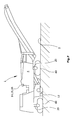
- FIG. 2 shows the construction machine according to FIG. 1 with raised milling drum
- FIG. 3 shows a power train of the construction machine
- FIG. 4 shows an illustration showing the control device and monitoring device
- FIG. 5 shows an alternative illustration
- FIG. 6 shows a flow diagram for detecting the interruption and the intended continuation of the working operation
- FIG. 7 shows a further self-propelled construction machine.
- FIG. 1 shows a self-propelled construction machine 1 for working ground pavements 2 .
- the construction machine 1 comprises, as a minimum, a machine frame 4 .
- the construction machine comprises a height-adjustable milling drum 12 for working the ground pavement 2 where, in a working operation, the milling drum 12 works the ground pavement 2 .
- the milling drum 12 may be accommodated in a milling drum housing.
- the milling drum housing may comprise a left and a right edge protector 24 at the end sides, a hold-down device at the front side and a scraper 22 at the rear side, where the same close the working chamber of the milling drum 12 towards the outside.
- the construction machine 1 comprises a control device 14 for monitoring and controlling the milling depth of the milling drum 12 and the speed of the construction machine 1 .
- the milling drum 12 is driven by a drive unit 6 .
- the drive unit 6 is preferably a drive motor, specifically, a combustion engine. Alternatively, the drive unit may also be an electric or hydraulic motor.
- the construction machine 1 furthermore comprises front and rear travelling devices 8 , 9 . Said travelling devices 8 , 9 may be wheels or tracked ground-engaging units.
- the rear travelling devices 9 are connected to the machine frame 4 in a height-adjustable fashion via lifting columns 20 by means of, for example, piston-cylinder units.
- the front travelling device 8 is also connected to the machine frame 4 .
- the front travelling devices 8 may, in a different fashion than depicted, also be connected to the machine frame via lifting columns.
- the construction machine 1 or the machine frame 4 can be adjusted in height relative to the ground pavement by means of the lifting columns 20 .
- the machine frame 4 is adjusted in height by adjusting the lifting columns 20 , and as a result, the milling drum 12 mounted in the machine frame 4 is adjusted in height as well.
- the construction machine 1 is depicted with the milling drum 12 raised.
- the milling drum may be adjustable in height relative to the machine frame.
- an interruption of the working operation is detected, and the drive of the milling drum 12 is interrupted in the event of a detected interruption of the working operation.
- the monitoring device 15 detects an interruption of the working operation, and when detecting the interruption of the working operation, the monitoring device 15 emits a signal to interrupt the drive of the milling drum 12 .
- the monitoring device 15 monitors operating parameters of the construction machine 1 to detect the interruption of the working operation.
- the operating parameters are compared with specified limit values which may be stored in the monitoring device.
- the operating parameters which are monitored to detect the interruption of the working operation may specifically be the actual speed of the construction machine 1 and/or the actual milling depth.
- the working operation is interrupted. Furthermore, the working operation is also interrupted when the milling drum 12 is no longer engaged with the ground pavement 2 . This is the case, for example, in FIG. 2 . There, the milling drum 12 is no longer engaged with the ground pavement 2 . In this case, the working operation is interrupted.
- the power train of the construction machine 1 is depicted in FIG. 3 .
- the driving power is transmitted, via a drive unit 6 which is preferably a drive motor, specifically a combustion engine, to the milling drum 12 via a power transmission device 13 .
- the power transmission device comprises a coupling 7 and a drum drive 10 .
- the drum drive 10 drives the milling drum 12 by means of a belt drive 11 .
- a signal is emitted to the power transmission device which interrupts the drive of the milling drum 12 .
- the drive unit 6 is decoupled from the milling drum 12 by means of the coupling 7 .
- FIG. 4 an illustration is depicted which depicts the signal paths between the control device 14 , monitoring device 15 , operating device 16 , travel drive, height adjustment, drive unit 6 and milling drum 12 .
- the monitoring device 15 monitors operating parameters of the construction machine to detect the interruption of the working operation.
- the monitoring device queries the operating parameters from the control device 14 .
- the operating parameters which can be queried from the control device 14 are, among other things, the actual speed, the nominal speed, the nominal milling depth and the actual milling depth.
- the monitoring device 15 compares the operating parameters queried with specified limit values.
- the actual operating parameters are queried specifically to detect the interruption of the working operation.
- the actual speed which is referred to as actual advance rate, and/or the actual milling depth are thus specifically queried by the monitoring device 15 and compared with specified limit values.
- the control unit receives measuring data from sensors about the actual speed and the actual milling depth.
- the sensors for determining the actual speed may be arranged at parts of the travel drive.
- the travel drive comprises the travelling devices and running gear motors for driving the travelling devices, where one running gear motor is preferably assigned to each travelling device.
- the running gear motors may be hydraulic motors and may be driven by a common hydraulic variable displacement pump.
- Sensors of any other kind may also be used, however, which are able to determine the actual speed of the construction machine 1 .
- the actual milling depth is detected by sensors which are arranged at the height adjustment feature, for example, at the lifting columns or at the piston-cylinder units.
- the sensors may also be arranged in any other position, however, provided that the same are able to determine the actual milling depth. They may be arranged, for example, at the scraper blade 22 and/or at the side plates 24 . Further sensors for determining the milling depth, such as ultrasonic sensors, are known to the person skilled in the art.
- the exact procedure to determine the milling depth is not relevant to the invention; it must merely be ensured that one can be detected reliably when the milling drum is disengaged from the ground surface in order to detect an interruption of the working operation.
- the monitoring device determines, by comparison of the operating parameters with specified limit values, that the working operation is interrupted, the monitoring device emits a signal to the power transmission device 13 .
- the power transmission device 13 comprises means for interrupting the flux of power.
- the means for interrupting the flux of power is preferably a coupling as it is depicted in FIG. 3 .
- the drive of the milling drum is interrupted with the aid of the means for interrupting the flux of power.
- the means for interrupting the flux of power is a coupling 7 , the milling drum 12 is decoupled from the drive unit 6 in case of an interrupted working operation.
- the monitoring device 15 After the drive of the milling drum 12 has been interrupted, it is detected as to whether the working operation is to be continued. When detecting the intended continuation of the working operation, the milling drum 12 is driven again. To this effect, the monitoring device 15 , following the interruption of the drive of the milling drum 12 , detects as to whether the working operation is to be continued, and when detecting the intended continuation of the working operation, emits a second signal for the renewed driving of the milling drum 12 . In this process, the monitoring device 15 emits the second signal for the renewed driving of the milling drum 12 specifically to the power transmission device 13 .
- the monitoring device 15 queries operating parameters from the control device 14 and compares the queried operating parameters with specified limit values which may be stored in the monitoring device 15 .
- the nominal operating parameters are specifically queried to detect the intended continuation of the working operation.
- the nominal speed and the nominal milling depth are preferably queried in this process. These may be queried from the control device and/or the operating device.
- the monitoring device 15 may also query the operating parameters directly from the sensors or directly from the operating device 16 , respectively.
- the monitoring device 15 may detect an interruption of the working operation and emit the signal to interrupt the drive of the milling drum only after a specified time delay.
- the monitoring device 15 may also delay the movement of the construction machine 1 and/or a lowering of the milling drum 12 until the milling drum 12 has reached a specified operating speed of revolution again. It is further depicted in FIG. 5 that sensors may also be arranged at the milling drum 12 which measure the speed of revolution of the milling drum 12 . To this effect, the monitoring device 15 may query the operating speed of revolution determined by a sensor from the control unit or directly from the sensors.
- the milling drum 12 may also be raised after detection of an interruption of the working operation.
- the milling drum 12 may then be driven again and then be lowered. In this way, it is ensured that the milling drum 12 is in contact with the ground pavement 2 only when the milling drum 12 has reached an operating speed of revolution.
- FIG. 6 shows a flow diagram for detecting the interruption of the working operation and the intended continuation of the working operation.
- the nominal speed of the milling machine queried from the control device 14 or from sensors is compared with a limit value in block 100 specifically to determine as to whether the advance rate, that is, the speed of the construction machine 1 is greater than 0.
- the actual milling depth determined from the control device 14 or from sensors is compared with a limit value in a subsequent step in block 110 , it being specifically determined as to whether the milling drum 12 is engaged with the ground at the adjusted milling depth.
- an interruption of the working operation is detected.
- the milling drum may be raised by a specified amount as depicted in block 101 .
- the drive of the milling drum is then interrupted in block 102 .
- the nominal milling depth which may also be queried from the control unit 14 or from the operating unit 16 , is monitored in block 103 , where it is monitored as to whether the same falls below a preadjusted limit value. It is thus monitored as to whether, in addition to the standstill of the machine, the milling drum 12 is also disengaged from the ground. If the nominal milling depth continues to be greater than the limit value, it is monitored in the next step in block 104 as to whether a nominal speed greater than zero has been adjusted again, that is, whether the machine operator wishes to resume the working operation by increasing the speed. The steps 103 and 104 are performed continuously during the standstill of the machine until either the milling depth is changed, or the advance rate is increased again.
- step 104 it may also be monitored in step 104 as to whether the nominal milling depth was increased by the machine operator, meaning whether the milling depth is to be increased while the machine is stationary.
- the drive of the milling drum is therefore interrupted in block 112 .
- it is monitored in block 113 as to whether a nominal milling depth has been adjusted again which is greater than the specified limit value.
- the actual and nominal speeds are not relevant as the road milling machine can be moved freely, for example, in manoeuvring mode while the milling drum is disengaged from the ground. If it was detected in the previously described block 103 that, with the drive of the milling drum already interrupted, the milling depth was reduced below the limit value and, as a consequence, the milling drum was disengaged from the ground, a jump is made to block 113 as the nominal and actual speeds do, in this case, also not have an influence on the detection of the continuation of the working operation.
- FIG. 7 shows a construction machine 1 as a so-called large milling machine which is different from the construction machine according to FIG. 1 in that, among other things, the front and rear travelling devices 40 are tracked ground-engaging units and the front as well as the rear travelling devices 40 are connected to the machine frame 4 via lifting columns.
- the detection of the interruption of the working operation or of the intended continuation of the working operation, respectively, is effected in an analogous fashion by means of monitoring the operating parameters.
- control device 14 and monitoring device 15 may be or comprise a multipurpose processor, a digital signal processor (DSP), an application-specific integrated circuit (ASIC), a field-programmable gate array (FPGA) or other programmable logic circuits, discrete gate or transistor logic, discrete hardware components, or a combination of the same, or may be part thereof, provided that they are programmable in order to perform the features described above.
- DSP digital signal processor
- ASIC application-specific integrated circuit
- FPGA field-programmable gate array
- a multipurpose processor may be a microprocessor, microcontroller, state machine, or a combination of computer devices, for example, a combination of a DSP and a microprocessor, a multitude of microprocessors, or any other type of known configuration.
- the procedural steps of the method described above may be implemented directly through hardware components, or through a software module that is executed by a processor, or a combination thereof.
- the software module may be located on a RAM memory, a flash memory, a ROM memory, an EPROM memory, an EEPROM memory, a register, a hard disk, a removable hard disk, a CD-ROM, or any other type of computer-readable storage medium.
- the computer-readable storage medium may be coupled with the control device and/or monitoring device so that the control device and/or the monitoring device can retrieve the information from the computer-readable storage medium and save information on the computer-readable storage medium.
- the computer-readable storage medium may alternatively also be an integral part of the control device and/or monitoring device.
- the control device and/or monitoring device and the computer-readable storage medium may be located in an ASIC.
- the ASIC may be located in a user terminal.
- the control device and/or monitoring device and/or the computer-readable storage medium may be located in a user terminal as discrete components.
Landscapes
- Engineering & Computer Science (AREA)
- Mining & Mineral Resources (AREA)
- Architecture (AREA)
- Civil Engineering (AREA)
- Structural Engineering (AREA)
- Mechanical Engineering (AREA)
- Road Repair (AREA)
- Operation Control Of Excavators (AREA)
Priority Applications (2)
| Application Number | Priority Date | Filing Date | Title |
|---|---|---|---|
| US16/665,396 US11492767B2 (en) | 2016-08-29 | 2019-10-28 | Method for working ground pavements, as well as self-propelled construction machine |
| US17/980,638 US20230119638A1 (en) | 2016-08-29 | 2022-11-04 | Method for working ground pavements, as well as self-propelled construction machine |
Applications Claiming Priority (3)
| Application Number | Priority Date | Filing Date | Title |
|---|---|---|---|
| DE102016216216.0 | 2016-08-29 | ||
| DE102016216216.0A DE102016216216A1 (de) | 2016-08-29 | 2016-08-29 | Verfahren zum Bearbeiten von Bodenbelägen, sowie selbstfahrende Baumaschine |
| DE102016216216 | 2016-08-29 |
Related Child Applications (1)
| Application Number | Title | Priority Date | Filing Date |
|---|---|---|---|
| US16/665,396 Continuation US11492767B2 (en) | 2016-08-29 | 2019-10-28 | Method for working ground pavements, as well as self-propelled construction machine |
Publications (2)
| Publication Number | Publication Date |
|---|---|
| US20180058020A1 US20180058020A1 (en) | 2018-03-01 |
| US10465347B2 true US10465347B2 (en) | 2019-11-05 |
Family
ID=59269862
Family Applications (3)
| Application Number | Title | Priority Date | Filing Date |
|---|---|---|---|
| US15/679,349 Active US10465347B2 (en) | 2016-08-29 | 2017-08-17 | Method for working ground pavements, as well as self-propelled construction machine |
| US16/665,396 Active 2037-09-07 US11492767B2 (en) | 2016-08-29 | 2019-10-28 | Method for working ground pavements, as well as self-propelled construction machine |
| US17/980,638 Pending US20230119638A1 (en) | 2016-08-29 | 2022-11-04 | Method for working ground pavements, as well as self-propelled construction machine |
Family Applications After (2)
| Application Number | Title | Priority Date | Filing Date |
|---|---|---|---|
| US16/665,396 Active 2037-09-07 US11492767B2 (en) | 2016-08-29 | 2019-10-28 | Method for working ground pavements, as well as self-propelled construction machine |
| US17/980,638 Pending US20230119638A1 (en) | 2016-08-29 | 2022-11-04 | Method for working ground pavements, as well as self-propelled construction machine |
Country Status (4)
| Country | Link |
|---|---|
| US (3) | US10465347B2 (fr) |
| EP (1) | EP3290585B1 (fr) |
| CN (2) | CN208136685U (fr) |
| DE (1) | DE102016216216A1 (fr) |
Cited By (2)
| Publication number | Priority date | Publication date | Assignee | Title |
|---|---|---|---|---|
| US11203841B2 (en) | 2020-04-01 | 2021-12-21 | Caterpillar Paving Products Inc. | Machine, system, and method for automated milling exit cut operation |
| US11492767B2 (en) * | 2016-08-29 | 2022-11-08 | Wirtgen Gmbh | Method for working ground pavements, as well as self-propelled construction machine |
Families Citing this family (5)
| Publication number | Priority date | Publication date | Assignee | Title |
|---|---|---|---|---|
| US10844557B2 (en) * | 2019-03-27 | 2020-11-24 | Caterpillar Paving Products Inc. | Tool depth setting |
| US11041276B2 (en) * | 2019-03-27 | 2021-06-22 | Caterpillar Paving Products Inc. | Tool exposed status and lockouts |
| US10876260B2 (en) | 2019-03-27 | 2020-12-29 | Caterpillar Paving Products Inc. | Accurate tool depth control |
| DE102019210644A1 (de) * | 2019-07-18 | 2021-01-21 | Wirtgen Gmbh | Selbstfahrende Baumaschine und Verfahren zum Bearbeiten von Bodenbelägen |
| ES2971815B2 (es) * | 2022-11-03 | 2024-12-20 | Multiservicios Triton S L | Equipo de rotura mecánica |
Citations (39)
| Publication number | Priority date | Publication date | Assignee | Title |
|---|---|---|---|---|
| US2311891A (en) | 1941-04-17 | 1943-02-23 | Tyson Harry | Road grooving machine |
| US3606742A (en) | 1969-04-05 | 1971-09-21 | Franz Wieneke | Arrangement for the automatic control of the threshing process on combine harvesters |
| US3750762A (en) | 1971-08-19 | 1973-08-07 | Omsteel Ind Inc | Speed control system for vehicle mounting a work performing device |
| US4043402A (en) | 1975-03-24 | 1977-08-23 | Koehring Company | Soil stabilizer machine with detachable hydraulic motor structure driving rotatably mounted cutting elements |
| US4277898A (en) | 1979-12-26 | 1981-07-14 | J. I. Case Company | Hydraulic control system for excavating machine |
| US4333685A (en) | 1980-06-09 | 1982-06-08 | Federal-Mogul Corporation | Road surfacing apparatus |
| US4343513A (en) | 1980-08-25 | 1982-08-10 | Gomaco, Inc. | Method and power transmission system for operating a road planar machine |
| US4549610A (en) | 1979-06-05 | 1985-10-29 | Lely Cornelis V D | Vehicle with front and rear steerable wheels individually driven by hydraulic motors |
| US4588231A (en) | 1982-01-27 | 1986-05-13 | Concrete Safety Equipment, Inc. | Pavement surfacing machine |
| US4614305A (en) | 1984-02-24 | 1986-09-30 | Mem Muszaki Intezet | Apparatus for controlling and indicating speed and load of mobile chopping machine |
| US4655634A (en) | 1985-09-23 | 1987-04-07 | Dresser Industries, Inc. | Road planer control and safety system |
| US4903780A (en) | 1986-07-11 | 1990-02-27 | Elda Barbieri | Mobile, self-propelled crushing machine |
| US4929121A (en) * | 1989-09-05 | 1990-05-29 | Caterpillar Paving Products Inc. | Control system for a road planer |
| US5190398A (en) | 1991-03-12 | 1993-03-02 | Swisher Jr George W | Apparatus for preparing a road bed |
| US5318378A (en) * | 1992-09-28 | 1994-06-07 | Caterpillar Paving Products Inc. | Method and apparatus for controlling a cold planer in response to a kickback event |
| US5415495A (en) | 1993-07-19 | 1995-05-16 | Surface Preparation Technologies, Inc. | Cutting machine and a method for its use |
| US5879056A (en) | 1997-04-25 | 1999-03-09 | Caterpillar Inc. | Kickback protection device and method of use |
| US6170341B1 (en) | 1997-05-30 | 2001-01-09 | Schaeff Incorporated | Load sensing system |
| US6186248B1 (en) | 1995-12-12 | 2001-02-13 | Boart Longyear Company | Closed loop control system for diamond core drilling |
| US6338281B1 (en) | 1997-08-13 | 2002-01-15 | Reliance Electric Technologies, Llc | Bearing apparatus having integrated load sensing arrangement |
| US6407475B1 (en) | 1999-05-25 | 2002-06-18 | Rolls-Royce Plc | Bearing load control |
| US6558072B2 (en) | 2001-05-15 | 2003-05-06 | Caterpillar Paving Products Inc. | Speed control system for a work machine |
| WO2003064770A1 (fr) | 2002-01-30 | 2003-08-07 | Wirtgen Gmbh | Fraiseuse routiere fonctionnant de maniere optimale |
| DE10213017A1 (de) | 2002-03-22 | 2003-10-09 | Wirtgen Gmbh | Verfahren zum Optimieren eines Schneidprozesses bei Straßenfräsmaschinen, sowie Fräsmaschine zum Bearbeiten von Straßendecken |
| US6921230B2 (en) | 2002-12-24 | 2005-07-26 | Diamond Products, Limited | Closed loop control system for pavement surfacing machine |
| CN101078194A (zh) | 2006-05-22 | 2007-11-28 | 维特根有限公司 | 用于加工地表面的自驱动建筑机械以及方法 |
| US20080173740A1 (en) | 2007-01-18 | 2008-07-24 | Parker Carl D | Control system for cutter drum |
| DE112008000646T5 (de) | 2007-03-20 | 2010-05-12 | Volvo Construction Equipment Ab | Fräsmaschine mit Schneidtrommel-Geschwindigkeitssteuerung |
| EP2354310A2 (fr) | 2010-02-08 | 2011-08-10 | Wirtgen GmbH | Contrôle de commande adaptative pour fraiseuse |
| US20110266858A1 (en) | 2010-04-14 | 2011-11-03 | Bomag Gmbh | Apparatus For Processing Ground Surfaces |
| CN102644232A (zh) | 2012-05-09 | 2012-08-22 | 中联重科股份有限公司 | 铣刨机的控制方法和控制装置与铣刨机 |
| EP2722441A1 (fr) | 2012-10-19 | 2014-04-23 | Wirtgen GmbH | Engin automoteur et procédé de fonctionnement d'un engin automoteur |
| US8888194B2 (en) | 2012-03-21 | 2014-11-18 | Caterpillar Paving Products Inc. | Control module for milling rotor |
| US20140348585A1 (en) | 2013-05-24 | 2014-11-27 | Bomag Gmbh | Self-Propelled Ground Milling Machine For Processing Ground Surfaces Having A Milling Device |
| EP2840183A1 (fr) | 2013-08-23 | 2015-02-25 | Wirtgen GmbH | Engin autopropulsé et procédé de fonctionnement d'un engin automoteur |
| DE102014001885A1 (de) | 2014-02-12 | 2015-08-13 | Bomag Gmbh | Verfahren zur Optimierung einer Betriebsfunktion einer Bodenfräsmaschine und Bodenfräsmaschine |
| WO2016102410A1 (fr) | 2014-12-23 | 2016-06-30 | Wirtgen Gmbh | Engin de construction automoteur et procédé pour faire fonctionner un engin de construction automoteur |
| DE102015002426A1 (de) | 2014-12-30 | 2016-06-30 | Bomag Gmbh | Bodenfräsmaschine und Verfahren zum Verstellen des Abstreiferschildes einer Bodenfräsmaschine |
| US20170233959A1 (en) | 2016-02-16 | 2017-08-17 | Wirtgen Gmbh | Self-propelled construction machine and method for operating a self propelled construction machine |
Family Cites Families (1)
| Publication number | Priority date | Publication date | Assignee | Title |
|---|---|---|---|---|
| DE102016216216A1 (de) * | 2016-08-29 | 2018-03-01 | Wirtgen Gmbh | Verfahren zum Bearbeiten von Bodenbelägen, sowie selbstfahrende Baumaschine |
-
2016
- 2016-08-29 DE DE102016216216.0A patent/DE102016216216A1/de not_active Withdrawn
-
2017
- 2017-06-30 EP EP17178919.1A patent/EP3290585B1/fr active Active
- 2017-08-17 US US15/679,349 patent/US10465347B2/en active Active
- 2017-08-28 CN CN201721085271.7U patent/CN208136685U/zh active Active
- 2017-08-28 CN CN201710752528.8A patent/CN107780330B/zh active Active
-
2019
- 2019-10-28 US US16/665,396 patent/US11492767B2/en active Active
-
2022
- 2022-11-04 US US17/980,638 patent/US20230119638A1/en active Pending
Patent Citations (57)
| Publication number | Priority date | Publication date | Assignee | Title |
|---|---|---|---|---|
| US2311891A (en) | 1941-04-17 | 1943-02-23 | Tyson Harry | Road grooving machine |
| US3606742A (en) | 1969-04-05 | 1971-09-21 | Franz Wieneke | Arrangement for the automatic control of the threshing process on combine harvesters |
| US3750762A (en) | 1971-08-19 | 1973-08-07 | Omsteel Ind Inc | Speed control system for vehicle mounting a work performing device |
| US4043402A (en) | 1975-03-24 | 1977-08-23 | Koehring Company | Soil stabilizer machine with detachable hydraulic motor structure driving rotatably mounted cutting elements |
| US4549610A (en) | 1979-06-05 | 1985-10-29 | Lely Cornelis V D | Vehicle with front and rear steerable wheels individually driven by hydraulic motors |
| US4277898A (en) | 1979-12-26 | 1981-07-14 | J. I. Case Company | Hydraulic control system for excavating machine |
| US4333685A (en) | 1980-06-09 | 1982-06-08 | Federal-Mogul Corporation | Road surfacing apparatus |
| US4343513A (en) | 1980-08-25 | 1982-08-10 | Gomaco, Inc. | Method and power transmission system for operating a road planar machine |
| US4588231A (en) | 1982-01-27 | 1986-05-13 | Concrete Safety Equipment, Inc. | Pavement surfacing machine |
| US4614305A (en) | 1984-02-24 | 1986-09-30 | Mem Muszaki Intezet | Apparatus for controlling and indicating speed and load of mobile chopping machine |
| US4655634A (en) | 1985-09-23 | 1987-04-07 | Dresser Industries, Inc. | Road planer control and safety system |
| CA1266109A (fr) | 1985-09-23 | 1990-02-20 | Donald C. Baldwin | Systeme de commande sur engin d'arasement des surfaces de chaussees |
| US4903780A (en) | 1986-07-11 | 1990-02-27 | Elda Barbieri | Mobile, self-propelled crushing machine |
| US4929121A (en) * | 1989-09-05 | 1990-05-29 | Caterpillar Paving Products Inc. | Control system for a road planer |
| US5190398A (en) | 1991-03-12 | 1993-03-02 | Swisher Jr George W | Apparatus for preparing a road bed |
| US5318378A (en) * | 1992-09-28 | 1994-06-07 | Caterpillar Paving Products Inc. | Method and apparatus for controlling a cold planer in response to a kickback event |
| US5415495A (en) | 1993-07-19 | 1995-05-16 | Surface Preparation Technologies, Inc. | Cutting machine and a method for its use |
| US6186248B1 (en) | 1995-12-12 | 2001-02-13 | Boart Longyear Company | Closed loop control system for diamond core drilling |
| US5879056A (en) | 1997-04-25 | 1999-03-09 | Caterpillar Inc. | Kickback protection device and method of use |
| US6170341B1 (en) | 1997-05-30 | 2001-01-09 | Schaeff Incorporated | Load sensing system |
| US6338281B1 (en) | 1997-08-13 | 2002-01-15 | Reliance Electric Technologies, Llc | Bearing apparatus having integrated load sensing arrangement |
| US6407475B1 (en) | 1999-05-25 | 2002-06-18 | Rolls-Royce Plc | Bearing load control |
| US6558072B2 (en) | 2001-05-15 | 2003-05-06 | Caterpillar Paving Products Inc. | Speed control system for a work machine |
| WO2003064770A1 (fr) | 2002-01-30 | 2003-08-07 | Wirtgen Gmbh | Fraiseuse routiere fonctionnant de maniere optimale |
| DE10203732A1 (de) | 2002-01-30 | 2003-08-21 | Wirtgen Gmbh | Baumaschine |
| US7905682B2 (en) | 2002-01-30 | 2011-03-15 | Wirtgen Gmbh | Road milling machine with optimized operation |
| US7422391B2 (en) | 2002-01-30 | 2008-09-09 | Wirtgen Gmbh | Road milling machine with optimized operation |
| DE10213017A1 (de) | 2002-03-22 | 2003-10-09 | Wirtgen Gmbh | Verfahren zum Optimieren eines Schneidprozesses bei Straßenfräsmaschinen, sowie Fräsmaschine zum Bearbeiten von Straßendecken |
| US20140191560A1 (en) | 2002-03-22 | 2014-07-10 | Wirtgen Gmbh | Method For Optimizing A Cutting Process In Road Milling Machines, As Well As Milling Machine For Machining Road Coverings |
| US8668274B2 (en) | 2002-03-22 | 2014-03-11 | Wirtgen Gmbh | Method for optimizing a cutting process in road milling machines, as well as milling machine for machining road coverings |
| US7984953B2 (en) | 2002-03-22 | 2011-07-26 | Wirtgen Gmbh | Method and device for optimizing a cutting process in road milling machines |
| US6921230B2 (en) | 2002-12-24 | 2005-07-26 | Diamond Products, Limited | Closed loop control system for pavement surfacing machine |
| DE102006024123A1 (de) | 2006-05-22 | 2007-11-29 | Wirtgen Gmbh | Selbstfahrende Baumaschine, sowie Verfahren zum Bearbeiten von Bodenoberflächen |
| CN101078194A (zh) | 2006-05-22 | 2007-11-28 | 维特根有限公司 | 用于加工地表面的自驱动建筑机械以及方法 |
| US7530641B2 (en) | 2006-05-22 | 2009-05-12 | Wirtgen Gmbh | Automotive construction machine, as well as method for working ground surfaces |
| US20070286678A1 (en) * | 2006-05-22 | 2007-12-13 | Wirtgen Gmbh | Automotive construction machine, as well as method for working ground surfaces |
| US20080173740A1 (en) | 2007-01-18 | 2008-07-24 | Parker Carl D | Control system for cutter drum |
| US8465105B2 (en) | 2007-01-18 | 2013-06-18 | Cmi Terex Corporation | Control system for cutter drum |
| DE112008000646T5 (de) | 2007-03-20 | 2010-05-12 | Volvo Construction Equipment Ab | Fräsmaschine mit Schneidtrommel-Geschwindigkeitssteuerung |
| EP2354310A2 (fr) | 2010-02-08 | 2011-08-10 | Wirtgen GmbH | Contrôle de commande adaptative pour fraiseuse |
| US8128177B2 (en) | 2010-02-08 | 2012-03-06 | Wirtgen Gmbh | Adaptive advance drive control for milling machine |
| US8292371B2 (en) | 2010-02-08 | 2012-10-23 | Wirtgen Gmbh | Adaptive advance drive control for milling machine |
| US8632132B2 (en) | 2010-02-08 | 2014-01-21 | Wirtgen Gmbh | Adaptive advance drive control for milling machine |
| US20110266858A1 (en) | 2010-04-14 | 2011-11-03 | Bomag Gmbh | Apparatus For Processing Ground Surfaces |
| US8888194B2 (en) | 2012-03-21 | 2014-11-18 | Caterpillar Paving Products Inc. | Control module for milling rotor |
| CN102644232A (zh) | 2012-05-09 | 2012-08-22 | 中联重科股份有限公司 | 铣刨机的控制方法和控制装置与铣刨机 |
| EP2722441A1 (fr) | 2012-10-19 | 2014-04-23 | Wirtgen GmbH | Engin automoteur et procédé de fonctionnement d'un engin automoteur |
| US20150252539A1 (en) | 2012-10-19 | 2015-09-10 | Wirtgen Gmbh | Self-Propelled Building Machine |
| US20140348585A1 (en) | 2013-05-24 | 2014-11-27 | Bomag Gmbh | Self-Propelled Ground Milling Machine For Processing Ground Surfaces Having A Milling Device |
| EP2840183A1 (fr) | 2013-08-23 | 2015-02-25 | Wirtgen GmbH | Engin autopropulsé et procédé de fonctionnement d'un engin automoteur |
| US20160356004A1 (en) | 2013-08-23 | 2016-12-08 | Wirtgen Gmbh | Self-Propelled Construction Machine And Method For Operating A Self-Propelled Construction Machine |
| DE102014001885A1 (de) | 2014-02-12 | 2015-08-13 | Bomag Gmbh | Verfahren zur Optimierung einer Betriebsfunktion einer Bodenfräsmaschine und Bodenfräsmaschine |
| US20150227120A1 (en) | 2014-02-12 | 2015-08-13 | Bomag Gmbh | Method For Optimizing An Operating Function Of A Ground Milling Machine And Ground Milling Machine |
| WO2016102410A1 (fr) | 2014-12-23 | 2016-06-30 | Wirtgen Gmbh | Engin de construction automoteur et procédé pour faire fonctionner un engin de construction automoteur |
| DE102015002426A1 (de) | 2014-12-30 | 2016-06-30 | Bomag Gmbh | Bodenfräsmaschine und Verfahren zum Verstellen des Abstreiferschildes einer Bodenfräsmaschine |
| US20170233959A1 (en) | 2016-02-16 | 2017-08-17 | Wirtgen Gmbh | Self-propelled construction machine and method for operating a self propelled construction machine |
| EP3208382A1 (fr) | 2016-02-16 | 2017-08-23 | Wirtgen GmbH | Engin automobile et procédé de fonctionnement d'un engin automobile |
Non-Patent Citations (4)
| Title |
|---|
| Brochure re Model DA 120 available from ME-Messysteme GmbH of Hennigsdorf, Germany. (undated but admitted to be prior art). |
| China Search Report for corresponding patent application 201707525288, dated Aug. 28, 2017, 2 pages (not prior art). |
| European Search Report for corresponding European Patent application 17 17 8919 dated Jan. 8, 2018, 3 pp. (not prior art). |
| International Search Report in corresponding International Patent Application No. PCT/EP2015/080699 dated Feb. 15, 2016, 10 pp. (not prior art). |
Cited By (2)
| Publication number | Priority date | Publication date | Assignee | Title |
|---|---|---|---|---|
| US11492767B2 (en) * | 2016-08-29 | 2022-11-08 | Wirtgen Gmbh | Method for working ground pavements, as well as self-propelled construction machine |
| US11203841B2 (en) | 2020-04-01 | 2021-12-21 | Caterpillar Paving Products Inc. | Machine, system, and method for automated milling exit cut operation |
Also Published As
| Publication number | Publication date |
|---|---|
| CN107780330B (zh) | 2021-06-15 |
| US20230119638A1 (en) | 2023-04-20 |
| EP3290585B1 (fr) | 2020-04-29 |
| CN208136685U (zh) | 2018-11-23 |
| CN107780330A (zh) | 2018-03-09 |
| EP3290585A1 (fr) | 2018-03-07 |
| US20180058020A1 (en) | 2018-03-01 |
| US11492767B2 (en) | 2022-11-08 |
| US20200131721A1 (en) | 2020-04-30 |
| DE102016216216A1 (de) | 2018-03-01 |
Similar Documents
| Publication | Publication Date | Title |
|---|---|---|
| US11492767B2 (en) | Method for working ground pavements, as well as self-propelled construction machine | |
| US7530641B2 (en) | Automotive construction machine, as well as method for working ground surfaces | |
| US11603631B2 (en) | Self-propelled construction machine and method for operating a self- propelled construction machine | |
| US8888194B2 (en) | Control module for milling rotor | |
| JP6672128B2 (ja) | 作業機 | |
| JP4489697B2 (ja) | 建設機械のエンジン制御装置 | |
| US20110266858A1 (en) | Apparatus For Processing Ground Surfaces | |
| US20130226415A1 (en) | Continuously Productive Machine During Hydraulic System Overheat Condition | |
| CN112799390B (zh) | 自移动设备及其工作方法 | |
| JP2008101440A (ja) | ハイブリッド作業機械 | |
| JP2008111334A (ja) | ロードカッタ装置 | |
| US20090277743A1 (en) | Stall detection system for mower blade clutch engagement | |
| US10776638B2 (en) | Cold planer rotor collision avoidance | |
| RU2020103044A (ru) | Система и способ обнаружения затупленных и изношенных резцов | |
| US20170276530A1 (en) | Display apparatus for work machine | |
| US12239996B2 (en) | Material reduction machine with dynamic startup control | |
| KR20190067417A (ko) | 건설기계의 휠 슬립 제어 장치 및 제어 방법 | |
| KR101945480B1 (ko) | 트랙터 및 트랙터 제어 방법 | |
| WO2013053292A1 (fr) | Rouleau vibrant | |
| CN111267614A (zh) | 一种车辆主动限速控制方法及装置 | |
| CN113411034B (zh) | 无感无刷永磁电机堵转控制方法及变频控制器 | |
| JPH10266881A (ja) | 油圧駆動機械の油圧ポンプ制御方法およびその装置 | |
| KR20250061146A (ko) | 부하 감응 주행 제어 시스템 | |
| JP2018200005A (ja) | 作業機械の制御装置 | |
| KR20130076016A (ko) | 건설기계의 축 오일 온도에 따른 작업 모드 제어장치 |
Legal Events
| Date | Code | Title | Description |
|---|---|---|---|
| AS | Assignment |
Owner name: WIRTGEN GMBH, GERMANY Free format text: ASSIGNMENT OF ASSIGNORS INTEREST;ASSIGNORS:BERNING, CHRISTIAN;VOGT, ANDREAS;BARIMANI, CYRUS;SIGNING DATES FROM 20170822 TO 20170824;REEL/FRAME:043450/0486 |
|
| STPP | Information on status: patent application and granting procedure in general |
Free format text: RESPONSE TO NON-FINAL OFFICE ACTION ENTERED AND FORWARDED TO EXAMINER |
|
| STPP | Information on status: patent application and granting procedure in general |
Free format text: NOTICE OF ALLOWANCE MAILED -- APPLICATION RECEIVED IN OFFICE OF PUBLICATIONS |
|
| STPP | Information on status: patent application and granting procedure in general |
Free format text: PUBLICATIONS -- ISSUE FEE PAYMENT VERIFIED |
|
| STCF | Information on status: patent grant |
Free format text: PATENTED CASE |
|
| MAFP | Maintenance fee payment |
Free format text: PAYMENT OF MAINTENANCE FEE, 4TH YEAR, LARGE ENTITY (ORIGINAL EVENT CODE: M1551); ENTITY STATUS OF PATENT OWNER: LARGE ENTITY Year of fee payment: 4 |