US10519948B2 - Method of operating a pressurized drainage system for wastewater - Google Patents
Method of operating a pressurized drainage system for wastewater Download PDFInfo
- Publication number
- US10519948B2 US10519948B2 US15/455,165 US201715455165A US10519948B2 US 10519948 B2 US10519948 B2 US 10519948B2 US 201715455165 A US201715455165 A US 201715455165A US 10519948 B2 US10519948 B2 US 10519948B2
- Authority
- US
- United States
- Prior art keywords
- pump
- pump stations
- line section
- stations
- line
- Prior art date
- Legal status (The legal status is an assumption and is not a legal conclusion. Google has not performed a legal analysis and makes no representation as to the accuracy of the status listed.)
- Active, expires
Links
- 238000000034 method Methods 0.000 title claims abstract description 72
- 239000002351 wastewater Substances 0.000 title claims abstract description 72
- 238000012546 transfer Methods 0.000 claims abstract description 14
- 238000004140 cleaning Methods 0.000 claims abstract description 6
- 230000005540 biological transmission Effects 0.000 claims description 31
- 230000004913 activation Effects 0.000 claims description 30
- 230000015572 biosynthetic process Effects 0.000 claims description 21
- 238000011144 upstream manufacturing Methods 0.000 claims description 6
- 230000001419 dependent effect Effects 0.000 claims description 5
- 238000010295 mobile communication Methods 0.000 claims description 3
- 230000003213 activating effect Effects 0.000 claims 3
- 230000000694 effects Effects 0.000 abstract description 6
- 238000005755 formation reaction Methods 0.000 description 18
- 238000005086 pumping Methods 0.000 description 18
- 230000000875 corresponding effect Effects 0.000 description 12
- 230000008901 benefit Effects 0.000 description 11
- 238000013461 design Methods 0.000 description 11
- 230000008569 process Effects 0.000 description 11
- 238000004891 communication Methods 0.000 description 8
- 235000017276 Salvia Nutrition 0.000 description 5
- 241001072909 Salvia Species 0.000 description 5
- 230000002596 correlated effect Effects 0.000 description 4
- 238000012423 maintenance Methods 0.000 description 4
- 238000012545 processing Methods 0.000 description 4
- XLYOFNOQVPJJNP-UHFFFAOYSA-N water Substances O XLYOFNOQVPJJNP-UHFFFAOYSA-N 0.000 description 4
- 238000006073 displacement reaction Methods 0.000 description 3
- 230000006870 function Effects 0.000 description 3
- 230000005484 gravity Effects 0.000 description 3
- 238000013459 approach Methods 0.000 description 2
- 230000006399 behavior Effects 0.000 description 2
- 238000013439 planning Methods 0.000 description 2
- 230000009897 systematic effect Effects 0.000 description 2
- 230000007704 transition Effects 0.000 description 2
- 230000008859 change Effects 0.000 description 1
- 230000000295 complement effect Effects 0.000 description 1
- 230000001276 controlling effect Effects 0.000 description 1
- 230000002354 daily effect Effects 0.000 description 1
- 230000009849 deactivation Effects 0.000 description 1
- 238000011161 development Methods 0.000 description 1
- 238000010586 diagram Methods 0.000 description 1
- 230000008030 elimination Effects 0.000 description 1
- 238000003379 elimination reaction Methods 0.000 description 1
- 230000003203 everyday effect Effects 0.000 description 1
- 230000008570 general process Effects 0.000 description 1
- 238000009434 installation Methods 0.000 description 1
- 238000011017 operating method Methods 0.000 description 1
- 239000010865 sewage Substances 0.000 description 1
- 230000002123 temporal effect Effects 0.000 description 1
- 230000001960 triggered effect Effects 0.000 description 1
Images


Classifications
-
- E—FIXED CONSTRUCTIONS
- E03—WATER SUPPLY; SEWERAGE
- E03F—SEWERS; CESSPOOLS
- E03F3/00—Sewer pipe-line systems
- E03F3/02—Arrangement of sewer pipe-lines or pipe-line systems
-
- F—MECHANICAL ENGINEERING; LIGHTING; HEATING; WEAPONS; BLASTING
- F04—POSITIVE - DISPLACEMENT MACHINES FOR LIQUIDS; PUMPS FOR LIQUIDS OR ELASTIC FLUIDS
- F04B—POSITIVE-DISPLACEMENT MACHINES FOR LIQUIDS; PUMPS
- F04B49/00—Control, e.g. of pump delivery, or pump pressure of, or safety measures for, machines, pumps, or pumping installations, not otherwise provided for, or of interest apart from, groups F04B1/00 - F04B47/00
- F04B49/06—Control using electricity
-
- E—FIXED CONSTRUCTIONS
- E03—WATER SUPPLY; SEWERAGE
- E03F—SEWERS; CESSPOOLS
- E03F5/00—Sewerage structures
- E03F5/22—Adaptations of pumping plants for lifting sewage
-
- F—MECHANICAL ENGINEERING; LIGHTING; HEATING; WEAPONS; BLASTING
- F04—POSITIVE - DISPLACEMENT MACHINES FOR LIQUIDS; PUMPS FOR LIQUIDS OR ELASTIC FLUIDS
- F04B—POSITIVE-DISPLACEMENT MACHINES FOR LIQUIDS; PUMPS
- F04B23/00—Pumping installations or systems
- F04B23/02—Pumping installations or systems having reservoirs
- F04B23/021—Pumping installations or systems having reservoirs the pump being immersed in the reservoir
-
- F—MECHANICAL ENGINEERING; LIGHTING; HEATING; WEAPONS; BLASTING
- F04—POSITIVE - DISPLACEMENT MACHINES FOR LIQUIDS; PUMPS FOR LIQUIDS OR ELASTIC FLUIDS
- F04B—POSITIVE-DISPLACEMENT MACHINES FOR LIQUIDS; PUMPS
- F04B49/00—Control, e.g. of pump delivery, or pump pressure of, or safety measures for, machines, pumps, or pumping installations, not otherwise provided for, or of interest apart from, groups F04B1/00 - F04B47/00
- F04B49/02—Stopping, starting, unloading or idling control
-
- F—MECHANICAL ENGINEERING; LIGHTING; HEATING; WEAPONS; BLASTING
- F04—POSITIVE - DISPLACEMENT MACHINES FOR LIQUIDS; PUMPS FOR LIQUIDS OR ELASTIC FLUIDS
- F04D—NON-POSITIVE-DISPLACEMENT PUMPS
- F04D13/00—Pumping installations or systems
- F04D13/12—Combinations of two or more pumps
-
- F—MECHANICAL ENGINEERING; LIGHTING; HEATING; WEAPONS; BLASTING
- F04—POSITIVE - DISPLACEMENT MACHINES FOR LIQUIDS; PUMPS FOR LIQUIDS OR ELASTIC FLUIDS
- F04D—NON-POSITIVE-DISPLACEMENT PUMPS
- F04D15/00—Control, e.g. regulation, of pumps, pumping installations or systems
-
- F—MECHANICAL ENGINEERING; LIGHTING; HEATING; WEAPONS; BLASTING
- F04—POSITIVE - DISPLACEMENT MACHINES FOR LIQUIDS; PUMPS FOR LIQUIDS OR ELASTIC FLUIDS
- F04D—NON-POSITIVE-DISPLACEMENT PUMPS
- F04D15/00—Control, e.g. regulation, of pumps, pumping installations or systems
- F04D15/02—Stopping of pumps, or operating valves, on occurrence of unwanted conditions
- F04D15/0209—Stopping of pumps, or operating valves, on occurrence of unwanted conditions responsive to a condition of the working fluid
- F04D15/0218—Stopping of pumps, or operating valves, on occurrence of unwanted conditions responsive to a condition of the working fluid the condition being a liquid level or a lack of liquid supply
-
- F—MECHANICAL ENGINEERING; LIGHTING; HEATING; WEAPONS; BLASTING
- F04—POSITIVE - DISPLACEMENT MACHINES FOR LIQUIDS; PUMPS FOR LIQUIDS OR ELASTIC FLUIDS
- F04D—NON-POSITIVE-DISPLACEMENT PUMPS
- F04D15/00—Control, e.g. regulation, of pumps, pumping installations or systems
- F04D15/02—Stopping of pumps, or operating valves, on occurrence of unwanted conditions
- F04D15/029—Stopping of pumps, or operating valves, on occurrence of unwanted conditions for pumps operating in parallel
-
- G—PHYSICS
- G05—CONTROLLING; REGULATING
- G05B—CONTROL OR REGULATING SYSTEMS IN GENERAL; FUNCTIONAL ELEMENTS OF SUCH SYSTEMS; MONITORING OR TESTING ARRANGEMENTS FOR SUCH SYSTEMS OR ELEMENTS
- G05B15/00—Systems controlled by a computer
- G05B15/02—Systems controlled by a computer electric
-
- E—FIXED CONSTRUCTIONS
- E03—WATER SUPPLY; SEWERAGE
- E03F—SEWERS; CESSPOOLS
- E03F2201/00—Details, devices or methods not otherwise provided for
- E03F2201/30—Devices providing a sequential discharge in sewer systems
-
- F—MECHANICAL ENGINEERING; LIGHTING; HEATING; WEAPONS; BLASTING
- F05—INDEXING SCHEMES RELATING TO ENGINES OR PUMPS IN VARIOUS SUBCLASSES OF CLASSES F01-F04
- F05D—INDEXING SCHEME FOR ASPECTS RELATING TO NON-POSITIVE-DISPLACEMENT MACHINES OR ENGINES, GAS-TURBINES OR JET-PROPULSION PLANTS
- F05D2260/00—Function
- F05D2260/60—Fluid transfer
- F05D2260/607—Preventing clogging or obstruction of flow paths by dirt, dust, or foreign particles
Definitions
- Pressurized drainage systems have been known for decades and are used worldwide. Numerous applications in wastewater transport are based on this principle and can be found in the United States, Europe, Asia, and Africa. Thanks to their technological advantages, pressurized drainage systems are attractive alternatives to conventional, gravity-based wastewater transport. Pressurized drainage systems make it possible to create a wastewater infrastructure in areas in which systematic wastewater disposal is not possible, either for technical or economic reasons.
- the wastewater pipe can be part of an extensive hierarchical network of other wastewater pipes that lead to a central transfer station into which the pressure of the wastewater pipe network can be released.
- One or more of the above-mentioned pump stations can be connected to each of these wastewater pipes. During operation, they pump the collected wastewater into the wastewater pipe and “push” the wastewater already present therein forward toward the transfer station.
- the collecting tanks of a wastewater pump station generally hold between 100 and 150 L.
- the pumps located therein for example a displacement pump or centrifugal pump, are activated and deactivated as a function of the water level. If a certain upper threshold level is exceeded, activation occurs, and if the level falls below a lower threshold, the pump is shut off again. This occurs four times per day on average, with the total operating time being 6 minutes on average. Each operating interval of a pump station therefore has a duration of about 1.5 minutes.
- the pump station is therefore controlled in a decentralized manner as a function of the fill level.
- the pump stations each transmit status information indicating at least their pump standby status to a central controller and that, from the set of pump stations that are in pump standby in relation to one of the line sections, a group is formed such that the number of pump stations of the group corresponds at least to a minimum number of pump stations associated with this line section, with the pump station or pump stations of the group then being activated simultaneously by the central controller.
- the term “group” does not necessarily mean “several pump stations.” Rather, in the simplest of cases, a group can also include only one pump station, namely if a minimum number of “1” is associated with the respective line section.
- the minimum flow rate in a line section is ensured by grouping a number of the pump stations that are in pump standby into a group that corresponds to a minimum number of pump stations for this line section. According to the invention, such a minimum number of pump stations for achieving the minimum flow rate in the corresponding line section is determined empirically for each line section of the pressurized drainage system and used for the method.
- the determination of the group requires the central controller to have information on which of the pump stations are in pump standby.
- the pump stations transmit information on their pump standby status to the central controller. Standby status does not exist only when the exceeding of an upper threshold level indicates that the collecting tank is full, as in the prior art. Instead, a pump station can already be regarded as being ready to pump if it has collected at least a certain minimum quantity of wastewater, for example between 30% and 50% of its normal capacity (without reserve capacities). In the case of a pump station with a collecting tank having a 100 L nominal capacity, this means that it is already in pump standby if at least 30 L or at least 50 L have been collected.
- the transmission of the status information from the pump stations to the central controller can occur automatically.
- An event that triggers the transmission can be the reaching of a certain fill level, the reaching of a certain time, the lapsing of the next transmission interval, or the receipt of a query signal requesting that the pump stations report on their pump standby status. A combination of these events is also possible.
- the transmission of the status information as a result of the reaching of a certain fill level offers the advantage that the central controller need no longer analyze the information. After all, pump stations that report to the central controller as a result of exceeding a level are by definition in pump standby.
- the central controller queries the pump stations for the status information in polling intervals.
- the polling interval or transmission interval can be between 10 and 15 minutes.
- an interrogation signal is transmitted from the central controller, one possibility is for all pump stations to report to the central controller by sending information regarding whether they are in pump standby. In that case, several of the pump stations will indicate that they are ready to pump, whereas the other pump stations will indicate that they are not ready to pump. Alternatively, it is possible for only those pump stations that are in fact ready to pump to report back. This offers the advantage that the central controller also only receives information concerning pump stations that are in fact in standby, thus eliminating the need for a separate analysis as to which of the pump stations are in standby and which are not.
- the status information can be binary information concerning the under- and overshooting of a certain fill level threshold, for example, it can be decimal information regarding the fill level. Furthermore, the binary and decimal information can also be transmitted together. Compared to decimal information, the use of binary information has the advantage that the information regarding pump standby status follows directly from it and the controller does not have to first check which pump stations are ready for operation and which are not.
- the fill level has the advantage that the central controller knows how high the fill level is in the pump stations independently of the fill level. This enables a dynamic selection to be made on the part of the central controller, for example, regarding the level above which a pump standby status exists.
- the threshold level can be reduced, for example set to 30%. It can therefore be assumed that this condition is met by more pump stations than when a threshold level of 50% of the nominal capacity is used.
- the pump stations acknowledge their activation to the central controller.
- the central controller can be certain which activation was successful and in which pump station a fault may have occurred.
- another activation attempt can be made, for example, or a warning message can be issued by the central controller or a maintenance order issued immediately.
- the formation of groups is repeated within the polling interval or transmission interval, particularly a number of times.
- a group is formed from the quantity of pump stations that are ready to pump, i.e. those pump stations that are in pump standby, two or more times within the polling interval or transmission interval, at least provided that sufficient pump stations are in standby and it is possible and sensible to form a group.
- the quantity of pump stations in standby is thus gradually worked off and the pump stations emptied.
- an additional 40 seconds can be expected to pass before emptying in the case of a 40 liter reserve capacity. What is more, the transmission of the activation signal can take several seconds. Accordingly, selecting a delay between 150 and 180 seconds for a 100 liter wastewater collecting tank of a pump station represents a conservative approach.
- the number of repetitions can preferably correspond to the greatest multiple of the delay that is less than the polling interval or transmission interval. For example, if the polling interval or transmission interval is 10 minutes, in the case of a delay of 3 minutes, a maximum of three groups can be formed, and if the polling or transmission interval is 15 minutes, up to five groups can be formed. Each attempt to form a group is referred to hereinafter as a cycle.
- the table or at least one of the tables also contains a maximum number of pump stations for each of the line sections. This is also used during the formation of groups. What is taken into account with the maximum number is that, in the case of several pump stations that are pumping simultaneously, their overall delivery rate is greater than the delivery rate that can be conducted through the connected wastewater pipe; the pump stations located downstream are working against the wastewater that is already flowing in the line section. This problem can be illustrated with the image that an overcrowded freeway can no longer accommodate cars that are waiting at the on-ramps. A maximum number of simultaneously active pump stations that should not be exceeded when forming groups can thus be correlated with each pressurized water line based on its respective diameter and the resulting maximum throughput. Especially energy-efficient operation can thus be achieved.
- a pump priority is assigned to each pump station. This makes it possible to order the pump stations of the same line section hierarchically.
- the pump priority can be assigned for every pump station, even for those that are connected to only one line section. If more pump stations in pump standby are associated with the identified line section than the maximum number indicates or allows, the group can then be formed from only those pump stations having the highest priorities. For example, if four pump stations in standby are present even though the maximum number of the corresponding line section is three, only the pump stations having the priorities one, two and three are grouped together. The pump station with priority four is not considered.
- the pump priority can be assigned such that a pump station of a line section has a greater priority the farther away it lies at the beginning of the respective line section toward flow. This also makes it possible for those pump stations to be activated first whose lifted wastewater travels the farthest to the transfer station, so that a cleaning effect is achieved in extensive line sections of the pressurized drainage system.
- the group can, on the one hand, be formed from the pump station(s) of the identified line section that are in standby and, on the other hand, be formed from one or more pump stations of at least one line section upstream from the identified line section that are in standby such that the minimum number of the identified line section is reached or even exceeded.
- This combination of pump stations from multiple line sections into a group optimally utilizes the quantity of pump stations that are ready to pump in order to achieve a cleaning effect.
- FIG. 1 is a conceptual representation of the system design of a pressurized drainage system according to the invention
- FIG. 2 is a schematic representation of a pump station
- FIG. 3 shows the network topology of a first exemplary pressurized drainage system
- FIG. 4 shows the network topology of a second exemplary pressurized drainage system
- FIG. 5 is a diagram of the superordinate method sequence
- FIG. 6 is a flowchart for the identification of the pump stations to be activated
- FIG. 7 is a flowchart for the identification of a line section
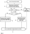
- FIG. 8 is a flowchart for the line group formation
- FIG. 9 is a flowchart for the identification of the next line section.
- FIG. 1 is a basic illustration of a pressurized wastewater-drainage system, with only a plurality of pump stations 2 , which are designated by the letters A to L, as well as the centralized communication structure, being depicted.
- the pump stations 2 are in radio communication with a central controller 3 .
- the central controller 3 is connected here for the sake of example via a network 8 , for example by internet, to a computer unit 9 . From this computer unit 9 , the central controller 3 can be monitored, configured, and/or controlled. For this purpose, the controller 3 can provide a web-based interface by means of a web server that can then be displayed on the computer unit 9 .
- the central controller 3 comprises a processing unit 5 , for example a computer system or a microprocessor system, to which a data memory 4 is connected.
- the data memory can be connected directly in one design variant and indirectly in another design variant to the processing unit 5 , for example via a network such as the internet.
- the data memory can be located in the cloud.
- a logic unit 7 for analyzing the data in the data memory 4 runs on the processing unit 5 .
- a transceiver unit 6 by means of which the radio communication to the pump stations 2 occurs is also connected to the processing unit 5 .
- the transceiver unit 6 can also be implemented in the form of two separate units, namely a transmitter unit on the one hand and a receiver unit on the other.
- FIG. 2 is an exemplary representation of a pump station 2 that can be used as pump station A . . . L.
- the pump station comprises a container 12 for collecting the wastewater as well as a pump 13 , for example a displacement pump or a centrifugal pump, that is in the lower region of the container 12 and presses the wastewater over a pressure line 14 into a wastewater pipe (not shown) during operation.
- the container 12 has a nominal capacity 19 of 100 liters, for example.
- the pump 13 is activated as soon as the nominal capacity is filled with wastewater. This is the case once the fill level reaches the first threshold level h_ready. As a result of the lifting of the wastewater, the fill level falls, and the pump 13 is deactivated again when the fill level reaches a lower threshold level h_stop.
- a reserve capacity 20 that comprises 40 liters, for example, begins above the first threshold level h_ready. Once this reserve capacity has been filled, the container 12 has a fill level that is designated by a second threshold level h_max. If this second threshold level is also exceeded, the container 12 can still accommodate an emergency capacity 21 until overflow occurs.
- a level sensor 17 is in the container in order to measure the fill level and is connected via a corresponding measuring line to a local control 15 provided outside of the container 12 .
- This pump control 15 is also connected to the pump 13 in order to control it, particularly to activate and deactivate it.
- the pump control 15 comprises a local transceiver unit 16 in order to receive communication from the central transceiver unit 6 on the one hand and to transmit communication to same on the other hand.
- FIG. 3 shows the topology of an exemplary network of wastewater pipes of the pressurized drainage system 1 with 26 pump stations 2 that are designated by the letters A to Z.
- the network consists of a total of nine line sections that are interconnected and designated by SA 1 to SA 9 .
- Each line section SA 1 to SA 9 extends between a starting point and an endpoint located downstream that together form the common nodes K 1 to K 10 of the network.
- Table 1 also shows a maximum number of pump stations for each diameter d1 to d9 as p_max.
- the minimum number p_min and the maximum number p_max can be identical for small-diameter wastewater pipes. That is the case, for example, for diameters d1 to d4.
- Table 2 The essential aspects of the topology of the network according to FIG. 3 are shown in Table 2 that is broken down into complementary sub-tables 2a and 2b.
- This Table 2 shows line sections SA 1 to SA 9 , whose pipe diameters and the pump stations A to Z associated with them.
- priorities are assigned to the pump stations A to Z and the line sections SA 1 to SA 9 .
- the pump priorities are distributed in relation to a line section.
- the pump stations of the same line section therefore have different priorities.
- the assigning of pump priorities is done here according to the position of the pump station within a line section. The farther the respective pump station at the beginning of the line section, the greater its priority.
- pump station A has pump priority 1
- pump station 8 has pump priority 2
- pump station C has pump priority 3
- pump station D has pump priority 4 .
- the bright priorities are assigned to the other pump stations E to Z in like manner.
- the assigning of the line priorities is basically only necessary for those line sections that have identical diameters; in the interest in being systematic, however, every line section is assigned a line priority. If a line section has a diameter that occurs only once on the network, that line section is assigned the highest priority “1.”
- the first, second, sixth, and seventh line sections SA 1 , SA 2 , SA 6 , SA 7 have the same diameter d4.
- those line sections that are farther from the transfer station are provided with a higher priority.
- the first and the second line sections SA 1 , SA 2 are assigned a higher priority than the sixth and the seventh line sections SA 6 , SA 7 .
- the first and second line sections SA 1 , SA 2 are topologically equivalent, so that a choice can be made here which line section receives the higher priority.
- the eighth line section SA 8 which also has the same diameter as the third and fourth line section SA 3 , SA 4 , is assigned the lowest priority because it, more specifically its endpoint K 6 , lies nearest the transfer station 10 .
- Both the pump priorities and the line priorities are shown in Table 2 and can therefore be checked by the central controller 3 , more particularly by its logic unit 7 .
- FIG. 5 shows the general process sequence of the method according to the invention.
- the pump stations 2 transmit information on their pump status to the central controller 3 .
- this is binary information to the effect that the corresponding pump station 2 is ready to pump. This means that a certain fill level, for example the first upper threshold level h_ready, has been reached or exceeded.
- the transmission of the status information is shown in block 32 .
- the transmission can occur automatically from the pump stations 2 , for example in transmission intervals of 10 minutes.
- the transmission of the status information can be triggered by a corresponding status query that is addressed by the central controller 3 to the pump stations 2 , for example in polling intervals of 10 minutes. In FIG. 5 , this is shown in block 30 that is upstream from block 32 .
- all of the pump stations 2 can react to this status query, or only those that are in fact in pump standby.
- This counting variable is increased by 1 in the next step (block 36 ). It indicates that a first cycle is beginning.
- a cycle means that a group of pump stations is being activated. In each ensuing cycle, another group is then activated by pump stations.
- a provision is made that several cycles are carried out within a transmission interval or polling interval. Since a cycle requires a certain amount of time, however, the total duration of the cycles must not exceed the duration of a transmission interval or polling interval.
- the core procedure of the method occurs, namely the identification of a group of pump stations 2 to be activated (block 40 ). If this inquiry yields pump stations to be activated, which is asked in block 41 , then these identified pump stations are activated (block 42 ). A time Tpump,max is then waited until the pump stations 2 have been emptied with certainty (block 44 ). For example, the waiting time can be 3 minutes. A data update then occurs (block 46 ), and the pump status of the previously activated pump stations stored in the data memory 4 , more particularly in Table 2, is updated, particularly changed to “not ready to pump.”
- the control variable i is then incremented, and the next cycle is carried out (block 36 ).
- the method steps named in blocks 38 - 46 are then repeated. If the query in block 41 reveals that no pump stations were found during the group identification, then the method is ended here for the time being. It then begins again with the next transmission interval or polling interval, i.e. in one design variant the pump station 2 transmits its pump status information again or, in another design variant, the transmission of this information is requested by the central controller 3 .
- FIG. 6 illustrates an exemplary process sequence for identifying the group of pump stations 2 to be activated within a cycle, thus implementing block 40 .
- a certain line section SAj is first identified with which the pump stations 2 that are in standby are correlated. This inquiry occurs in block 50 and is designated with “Identification of a line section SAj to be activated.”
- the number n of identified pump stations 2 is first compared to the minimum number p_min (SAj) of pump stations 2 required for the identified line section SAj (block 54 ).
- This minimum number p_min follows from the combination of the information in Tables 2 and 1. While Table 2 shows which diameter d1 to d9 the identified line section SAj has, Table 1 indicates for the corresponding diameter d1 to d9 how many pump stations are necessary in order to achieve the minimum volumetric flow rate.
- n is greater than the maximum number
- only a number of the pump stations 2 of the identified line section SAj that are in standby corresponding to the maximum number p_max are selected. This is done on the basis of the pump priority in Table 2. Those pump stations 2 having the highest priority are selected for activation (block 57 ). It should be noted that the priority becomes greater the smaller the numerical value indicating the parameter “priority” is.
- step 58 checks whether the identified line section SAj might optionally be combined with one or more line sections located upstream toward flow of the network. This is referred to as line group formation.
- Group line sections with a certain line section SA 1 to SA 9 are defined like the priorities before the beginning of the process and can be stored in the network table, Table 2.
- Group line sections are line sections of the network in which the activation of a connected pump stations 2 results in an increase in the flow rate in one of the subsequent line sections toward the transfer station 10 .
- the third and fourth line section SA 3 , SA 4 are direct group line sections of the fifth line section; see Table 2a.
- the fifth and eighth line section SA 5 , SA 8 are direct group line sections of the ninth line section SA 9 . Since the fifth line section SA 5 also has group lines, however, its group line sections are also indirect group line sections of the ninth line section SA 9 .
- SA 9 therefore has line sections SA 3 , SA 4 , SA 5 , and SA 8 as group line sections; cf. Table 2b.
- step 58 The query as to whether a line group formation is possible is made in step 58 .
- This query can be answered using Table 2, it being checked here whether at least one group line section is associated with the identified line section SAj. If this is not the case, a next line section is identified in block 80 , the procedure of which is shown in FIG. 9 and will be explained below.
- the line group formation is performed in step 60 , that is, the attempt is made to combine pump stations 2 of the identified line section SAj with pump stations 2 of the group line section(s).
- the line group formation is explained below with reference to FIG. 8 .
- An inquiry is made in step 59 as to whether this was successful.
- a next line section is identified as described previously (block 80 ). If so, then the pump stations 2 that are associated with the identified line section SAj on the one hand and the pump stations 2 of at least one of the group line sections of the identified line section SAj that are in standby on the other hand are selected for activation (block 72 ). The method then continues with step 41 in FIG. 5 .
- FIG. 7 shows an exemplary process sequence for the identification of a line section SAj to be activated.
- the starting point can be the line sections SA 1 to SA 9 , which are checked successively for the presence of pump stations 2 in standby, the smallest diameter, and the highest priority.
- the starting point can be the number of pump stations 2 in standby for which it is successively checked with which line section they are associated, which of these line sections has the smallest diameter, and which of them, in turn, has the highest priority.
- FIG. 7 shows the 1st variant of the method that implements block 50 in FIG. 6 .
- the line section identification begins with the initialization in step 81 , in which a control variable x with the value 1 identifying a line section and a parameter SAj that identifies an identified line section, are preset with the value 0.
- step 82 it is first inquired whether the xth line section SAx has pump stations 2 in standby. At the beginning of the method, it is of course the first line section SA 1 that is checked. If no pump stations 2 that are in standby are associated with this xth line section, the control variable x is incremented by one in step 83 , and the next line section SAx+1 is checked insofar as the total number SAmax of line sections SA 1 to SA 9 has not yet been reached (block 84 ). If the total number SAges has been reached the line section identification process ends after block 84 . The method then continues in step 51 of FIG. 6 .
- step 87 it is first checked in step 87 whether the diameter d)SAx) of the new potential candidate SAx is larger than the diameter d(SAj) of the previously identified candidate SAj. If this is the case, the new potential candidate SAx cannot be a better candidate, because the line section with the smallest diameter should always be identified. The control variable x is then incremented again, and the next line section SAx+2 is checked.
- step 87 if the check in step 87 reveals that the diameter d(SAx) is not larger, it is either smaller or of equal size. If the diameter d(SAx) is smaller (step 88 ), the potential new candidate SAx is indeed a candidate and is written into the parameter SAj. If the diameter d(SAx) is not smaller, and consequently of equal size, the line priorities are compared with one another in step 89 .
- the new potential candidate SAx is a better candidate and is written into the parameter SAj (block 86 ), and the next line section is checked (blocks 83 , 82 ). If the priority is not higher, the control variable x is incremented again, and the next line section is checked. Here, too, it should be noted that the priority becomes greater the smaller the numerical value indicating the parameter “priority” is.
- the line section identification process is ended as soon as it is determined in block 84 that all line sections SA 1 to SA 9 have been checked. The method then continues with step 51 in FIG. 6 .
- FIG. 9 An exemplary process sequence for identifying the next line section SAj+1 according to block 80 in FIG. 6 is shown in FIG. 9 .
- the process differs only slightly from the process shown in FIG. 7 for identifying a line section SAj to be activated.
- Process blocks in which the same steps are carried out in both line section identification processes are designated by the same reference numbers.
- One difference during the identification of the next line section according to block 80 is that the start value of control variable x is the index value j of the previously identified line section SAj increased by 1.
- the previous line section identification according to block 50 if it were carried out again instead of block 80 , would again yield the same line section SAj that was identified before, because nothing has changed in the pump standby statuses of the pump stations. For this reason, the line section identification according to FIG. 9 begins with the next line section SAj+1 that follows the previously identified line section SAj.
- block 84 It must first be checked whether the total number SAges of line sections has already been exceeded (block 84 ). In comparison to the procedure in FIG. 7 , block 84 is therefore provided upstream from block 82 . It is only when the check in block 84 shows that the total number SAges of line sections has not yet been exceeded that steps 82 , 83 , 85 , 86 , 87 , 88 , and 89 are carried out analogously to the line section identification according to block 50 in FIG. 7 . If the total number SAges of line sections has been exceeded, no next line section was able to be identified and the parameter SAj remains at 0 , so that it is subsequently determined in step 51 that no pump stations to be activated were able to be found. This determination in block 41 of FIG. 5 then leads to a termination of the current cycle without the starting of a new cycle. The method is then continued with the calling-up or transfer of new/current pump status information.
- step 62 it is determined in step 62 how many pump stations 2 are in pump standby in the group line sections GSA that are associated with the identified line section SAj. This is expressed in the number m. If the sum of the pump stations 2 of the identified line section SAj and its group line sections that are in standby does not reach the minimum number p_min(SAj) of pump stations 2 that is required for the identified line section SAj (see block 64 ), then the formation of group line is ended, since no pump stations 2 were able to be combined (blocks 67 , 70 ). The method then continues with step 59 in FIG. 6 .
- step 65 a check is then performed in step 65 to see whether the sum of the pump stations 2 of the identified line section SAj and its group line sections that are in standby exceeds the maximum number p_max(SAj) of pump stations 2 . If this is not the case, all of the pump stations 2 of the identified line section SAj and its group line sections that are in standby can be selected for activation in a group, step 66 .
- a number p_max-n of certain pump stations must be selected from among the quantity m of pump stations 2 of the group line sections that are in standby. This can be done on the basis of the pump priorities and the line priorities. Those p_max-n pump stations 2 of the group line sections are selected that have the highest priorities. If two or more pump stations of different group line sections have the same pump priority, then the pump station 2 is selected that is associated with the group line section having the higher line priority.
- n pump stations 2 of the identified line section SAj that are in standby and the number p_max(SAj) ⁇ n of pump stations of the group line sections of the identified line section SAj that are in standby are selected in step 68 for activation as a group.
- the line group formation 60 is ended at this point (block 70 ), and the method continues in step 59 in FIG. 6 .
- the wastewater pipe network according to FIG. 4 comprises line sections SA 1 to SA 4 .
- the four pump stations A, G, J, and K are connected to the first line section SA 1 .
- the two pump stations I and B are connected to the second line section SA 2 adjacent thereto.
- a third line section SA 3 comprises the three pump stations D, E, and F and merges together with the second line section SA 2 into a fourth line section SA 4 , to which the three pump stations C, H, and L are connected.
- the fourth line section has the largest pipe diameter.
- the line sections SA 2 and SA 3 have a smaller but identical pipe diameter.
- the first line section has the smallest pipe diameter.
- Table 3 shows the network topology in table form. All of the pump stations of the pressurized drainage system according to FIG. 4 have displacement pumps, i.e. pumps of type 2 according to Table 1.
- the line priority “1” is assigned to the first, second, and fourth line sections SA 1 , SA 2 , SA 4 , respectively. Only the third line section has a lower priority since its pipe diameter is identical to that of the second line section.
- the second line section has the higher priority in comparison to the third line section here, since it is part of a main line that is formed by the first, second, and third line section SA 1 , SA 2 , SA 4 .
- the second and third line section SA 2 , SA 3 each form a group line section of the fourth line section SA 4 .
- the pump station K has the highest priority because it is at the beginning of the first line section SA 1 .
- the pump stations A, G, and J can then be found downstream, so that pump station A has the priority 2 accordingly, pump station G the priority 3 accordingly, and pump station J the priority 4 accordingly.
- corresponding priorities are assigned to the other pump stations I, B, D, E, F, C, H, and L. Both the pump priorities and the line priorities as well as the group line correlations are contained in Table 3.
- the first cycle, steps 34 , 36 , 38 , as well as the identification of a group of pump stations to be activated (block 40 ) now begins. This, in turn, begins with the identification of a line section to be activated (block 50 ).
- the first line section SA 1 is identified first, since it has the pump station K that is in standby.
- the first line section SA 1 is written into the parameter SAj as a potential candidate.
- the second line section SA 2 is then checked. Since it includes the pump stations B that are in standby, it is considered first as a potential new candidate.
- the query in block 87 is positive, and the third line section is checked. However, that has no pump station that is ready for pumping, so the fourth line section is immediately checked next. While the fourth line section has pump station H that is in standby, it has a larger diameter d(SA 4 ) than the first line section d(SAj), so the query is positive in block 87 in this case, too, and the control variable x is incremented to the value 5. This results in the termination of the line section identification in block 84 , with the identified line section SAj being the first line section SA 1 .
- the query in block 54 is therefore positive.
- the query in block 55 is also positive, since the maximum number p_max(d4) of pump stations for diameter d4 is equal to 2.
- Pump station K is therefore selected according to block 56 as a pump station to be activated. It is then activated in block 42 . This is followed by a 3-minute wait, and then pump station K is eliminated from the set of pump stations that are in standby.
- the second line section SA 2 then follows from the line section identification (block 50 ), since it has pump stations B that are in standby, and has a smaller diameter than the fourth line section SA 4 .
- the query in step 54 indicates that the number n of pump stations n ⁇ 1 in standby is less than the minimum number p_min of pump stations. After all, according to Table 1, it is two for diameter d5. No line group formation is possible, since the second line section SA 2 according to Table 3 has not assigned any group line sections. From block 58 , the next line section SAj+1 is therefore then identified according to block 80 .
- line group formation is possible for the fourth line group formation SA 4 , the sum of all pump stations of the fourth line section SA 4 and its group line sections SA 2 and SA 3 that are in standby only amounts to two, so even a combination of pump stations that extends beyond one line section does not reach the required minimum number p_min (d6) of pump stations.
- the query in block 64 is therefore negative, as is the query in block 59 , so that the identification of the next line section SAj+1 is carried out again (block 80 ). However, this immediately reveals in block 84 that the total number of line sections SAges has been exceeded, so that the next line section SAj cannot be identified. Since the parameter SAj is zero as a result of its initialization in block 81 , it follows from block 51 that no pump stations to be activated were able to be found; see block 53 . This then leads to a negative result in block 41 , and it is then waited until the next polling interval starts or new status information is available.
- step 30 in FIG. 5 The next querying of pump statuses according to step 30 in FIG. 5 is performed after lapsing of the polling interval that is 10 minutes since the last query in this example.
- pump stations G, I, E, and D also report with status information that they are in standby. Consequently, seven pump stations are now ready for pumping: B, H, G, I, E, D. This situation results in the following activation sequence: G; I+B; E+D, so that five stations in standby have been emptied in three cycles at the end of the polling interval. Pump station H is left over.
- the first line section SA 1 is selected, since it has a pump stations that is in standby, namely pump stations associated with it, and it has the smallest pipe diameter d4 in the network. Also as in the previous example, it is then determined in block 54 that the minimum number p_min (d4) of pump stations that are in standby has been reached for the first line section and the maximum number of pump stations has also not been exceeded. After all, only the one pump station G is present that is in standby, and the minimum number p_min (d4) is one according to Table 1 and the maximum number p_max(d4) is two. Consequently, the pump station G is activated in steps 2 and 40 .
- step 40 Only this pump station forms the “group” identified in step 40 . There is a 3-minute wait in step 44 in order to ensure that the pump station G is completely emptied if other pump stations are being activated. Pump station G is then eliminated from the set of pump stations that are in standby, i.e. that are designated as not being ready for pumping in Table 3.
- the control variable i is then incremented in step 36 , and the second cycle begins.
- the pump stations B, H, I, E, D are now also ready for pumping.
- the line section identification in block 50 now identifies the second line section SA 2 , because the first line section SA 1 no longer has any pump stations in standby because it has the smallest diameter among the possible line sections SA 2 , SA 3 , SA 4 and because it has the higher priority in comparison to the third line section SA 3 that has the same diameter d5.
- the pump stations H, E, D are now also ready for pumping.
- the line section identification process in block 50 now identifies the third line section SA 3 , because the first and second line sections SA 1 , SA 2 no longer have any pump stations in standby, and because it has the smallest diameter d5 among the possible line sections SA 3 , SA 4 .
- step 56 the two pump stations E and D that are in standby are selected as a group and then activated together in step 42 . There is then another 3-minute wait, and the pump stations E and D are marked in Table 3 as being no longer ready for pumping. The third cycle is thus also ended. A fourth cycle is no longer possible, because that would extend beyond the polling interval.
- the first line section SA 1 is identified in the first cycle.
- the two highest-priority pump stations K and A of the first line section SA 1 are therefore selected and activated as a group.
- the first line section SA 1 is identified again, since it still includes pump stations G and J. It is determined in block 55 that the maximum number has not been exceeded, so that these two pump stations G and J are selected.
- the third cycle that now follows is identical to the second cycle of the second example, so that the pump stations I and B are activated. The method thus ends, and pump stations D, E, F as well as L, C, and A are left over.
Landscapes
- Engineering & Computer Science (AREA)
- General Engineering & Computer Science (AREA)
- Mechanical Engineering (AREA)
- Hydrology & Water Resources (AREA)
- Public Health (AREA)
- Water Supply & Treatment (AREA)
- Health & Medical Sciences (AREA)
- Life Sciences & Earth Sciences (AREA)
- Physics & Mathematics (AREA)
- General Physics & Mathematics (AREA)
- Automation & Control Theory (AREA)
- Sewage (AREA)
- Control Of Positive-Displacement Pumps (AREA)
- Electrical Discharge Machining, Electrochemical Machining, And Combined Machining (AREA)
- Physical Water Treatments (AREA)
Applications Claiming Priority (6)
| Application Number | Priority Date | Filing Date | Title |
|---|---|---|---|
| DE102016002991 | 2016-03-10 | ||
| DE102016002991.9 | 2016-03-10 | ||
| DE102016002991 | 2016-03-10 | ||
| DE102016003654 | 2016-03-30 | ||
| DE102016003654.0A DE102016003654A1 (de) | 2016-03-10 | 2016-03-30 | Verfahren zum Betreiben eines Druckentwässerungssystems für Abwässer |
| DE102016003654.0 | 2016-03-30 |
Publications (2)
| Publication Number | Publication Date |
|---|---|
| US20170260976A1 US20170260976A1 (en) | 2017-09-14 |
| US10519948B2 true US10519948B2 (en) | 2019-12-31 |
Family
ID=59700826
Family Applications (1)
| Application Number | Title | Priority Date | Filing Date |
|---|---|---|---|
| US15/455,165 Active 2037-08-10 US10519948B2 (en) | 2016-03-10 | 2017-03-10 | Method of operating a pressurized drainage system for wastewater |
Country Status (6)
| Country | Link |
|---|---|
| US (1) | US10519948B2 (pl) |
| EP (1) | EP3228767B1 (pl) |
| CN (1) | CN107178137B (pl) |
| DE (1) | DE102016003654A1 (pl) |
| HR (1) | HRP20192096T1 (pl) |
| PL (1) | PL3228767T3 (pl) |
Families Citing this family (1)
| Publication number | Priority date | Publication date | Assignee | Title |
|---|---|---|---|---|
| CN111561036B (zh) * | 2020-06-04 | 2021-12-21 | 毛飞燕 | 一种自增压除杂的卵形槽排水渠结构 |
Citations (8)
| Publication number | Priority date | Publication date | Assignee | Title |
|---|---|---|---|---|
| US5591010A (en) | 1995-01-19 | 1997-01-07 | Milltronics Ltd. | Time shift control of wastewater pumping system |
| US20030066804A1 (en) * | 2001-10-10 | 2003-04-10 | Tipton Gary A. | Wastewater pretreatment, gathering and final treatment process |
| US20100049781A1 (en) * | 2005-07-29 | 2010-02-25 | Cyber Solutions Inc. | Network management system and network management information collecting method |
| US20120222994A1 (en) | 2006-12-20 | 2012-09-06 | Data Flow Systems, Inc. | Fluid flow management system and associated methods |
| US8594851B1 (en) | 2006-12-20 | 2013-11-26 | Data Flow Systems, Inc. | Wastewater collection flow management system and techniques |
| US20140178211A1 (en) | 2012-12-20 | 2014-06-26 | Grundfos Holding A/S | Method for operating a wastewater pumping station |
| US20140286792A1 (en) | 2013-03-19 | 2014-09-25 | Control Techniques Limited | Pump Control |
| US20170051737A1 (en) * | 2015-08-17 | 2017-02-23 | Roderick Robert Ellsworth | Multi-source Pumping Optimization |
Family Cites Families (7)
| Publication number | Priority date | Publication date | Assignee | Title |
|---|---|---|---|---|
| JP2000112532A (ja) * | 1998-10-07 | 2000-04-21 | Sekisui Chem Co Ltd | 真空式下水道システムにおけるポンプ制御方法、並びに、真空式下水道システムのポンプ制御装置 |
| CN202273312U (zh) * | 2011-10-07 | 2012-06-13 | 山东华腾环保科技有限公司 | 一种用于城市下立交道路雨水排放的真空排水系统 |
| WO2013112633A1 (en) * | 2012-01-24 | 2013-08-01 | Chief Solutions, Inc. | Full-flow wastewater sewer systems |
| FR2993403B1 (fr) * | 2012-07-13 | 2014-08-22 | Commissariat Energie Atomique | Circuit integre sur soi comprenant un triac de protection contre des decharges electrostatiques |
| CN102936920B (zh) * | 2012-10-30 | 2014-12-10 | 山东华腾环保科技有限公司 | 一种真空雨水排水系统及方法 |
| CN204570913U (zh) * | 2015-03-20 | 2015-08-19 | 中国海诚工程科技股份有限公司 | 一种用于下洼区域雨水排水的节能提升装置 |
| CN105178415A (zh) * | 2015-09-10 | 2015-12-23 | 清华大学深圳研究生院 | 一种合流制排水管道的沉积物处理系统及方法 |
-
2016
- 2016-03-30 DE DE102016003654.0A patent/DE102016003654A1/de not_active Withdrawn
-
2017
- 2017-02-21 PL PL17000271T patent/PL3228767T3/pl unknown
- 2017-02-21 EP EP17000271.1A patent/EP3228767B1/de active Active
- 2017-03-10 US US15/455,165 patent/US10519948B2/en active Active
- 2017-03-10 CN CN201710139707.4A patent/CN107178137B/zh active Active
-
2019
- 2019-11-21 HR HRP20192096TT patent/HRP20192096T1/hr unknown
Patent Citations (8)
| Publication number | Priority date | Publication date | Assignee | Title |
|---|---|---|---|---|
| US5591010A (en) | 1995-01-19 | 1997-01-07 | Milltronics Ltd. | Time shift control of wastewater pumping system |
| US20030066804A1 (en) * | 2001-10-10 | 2003-04-10 | Tipton Gary A. | Wastewater pretreatment, gathering and final treatment process |
| US20100049781A1 (en) * | 2005-07-29 | 2010-02-25 | Cyber Solutions Inc. | Network management system and network management information collecting method |
| US20120222994A1 (en) | 2006-12-20 | 2012-09-06 | Data Flow Systems, Inc. | Fluid flow management system and associated methods |
| US8594851B1 (en) | 2006-12-20 | 2013-11-26 | Data Flow Systems, Inc. | Wastewater collection flow management system and techniques |
| US20140178211A1 (en) | 2012-12-20 | 2014-06-26 | Grundfos Holding A/S | Method for operating a wastewater pumping station |
| US20140286792A1 (en) | 2013-03-19 | 2014-09-25 | Control Techniques Limited | Pump Control |
| US20170051737A1 (en) * | 2015-08-17 | 2017-02-23 | Roderick Robert Ellsworth | Multi-source Pumping Optimization |
Also Published As
| Publication number | Publication date |
|---|---|
| PL3228767T3 (pl) | 2020-02-28 |
| HRP20192096T1 (hr) | 2020-02-21 |
| US20170260976A1 (en) | 2017-09-14 |
| DE102016003654A1 (de) | 2017-09-14 |
| CN107178137A (zh) | 2017-09-19 |
| EP3228767A1 (de) | 2017-10-11 |
| EP3228767B1 (de) | 2019-08-21 |
| CN107178137B (zh) | 2019-12-20 |
Similar Documents
| Publication | Publication Date | Title |
|---|---|---|
| US8594851B1 (en) | Wastewater collection flow management system and techniques | |
| US8600568B2 (en) | Fluid flow management system and associated methods | |
| US8983667B2 (en) | Fluid flow management through a wastewater level manipulation system and associated methods | |
| CN101401371B (zh) | 具有无线地址域向现场设备地址域转换的控制系统 | |
| CN102244898A (zh) | 一种基于群组的流量控制方法、设备以及系统 | |
| CN102833352A (zh) | 分布式缓存管理系统和实现分布式缓存管理的方法 | |
| CN115460124B (zh) | 跨机房传输链路优化的方法、装置、设备和存储介质 | |
| WO2011049981A2 (en) | Systems and methods for fueling management | |
| EP4557095A1 (en) | Internet of vehicles platform expansion and contraction method and system, and storage medium | |
| NO328364B1 (no) | Persistensvektorbasert tildeling av takt eller overforingshastighet | |
| US10519948B2 (en) | Method of operating a pressurized drainage system for wastewater | |
| JP2005537753A5 (pl) | ||
| WO2013113924A1 (en) | Radio device and application server adapted for automated m2m access evaluation and method of operating a radio device | |
| US7996534B2 (en) | File distribution in wireless networks | |
| CN107014440A (zh) | 一种基于云计算的城市供水系统监测设备 | |
| CN110209166B (zh) | 多个移动式服务机器人的协同控制方法、装置和存储介质 | |
| CN103052127B (zh) | 一种工业无线传感网络中调度通信的方法及装置 | |
| CN109617738B (zh) | 用户服务扩缩容的方法、系统和非易失性存储介质 | |
| CN112511579B (zh) | 事件通知方法、系统,服务器设备、计算机存储介质 | |
| CN108073445B (zh) | 基于分布式流计算的背压处理方法和系统 | |
| WO2013097363A1 (zh) | 一种调度数据共享装置的方法及系统 | |
| CN101159972B (zh) | 业务处理方法和处理系统以及业务控制点 | |
| JP2014512157A5 (pl) | ||
| CN104008062B (zh) | 内存管理方法及内存管理装置 | |
| KR100684497B1 (ko) | 무선 센서 네트워크에서 프락시가 가능한 클러스터링시스템과 그 클러스터링 방법 및 이를 기록한 기록매체 |
Legal Events
| Date | Code | Title | Description |
|---|---|---|---|
| AS | Assignment |
Owner name: WILO SE, GERMANY Free format text: ASSIGNMENT OF ASSIGNORS INTEREST;ASSIGNOR:SZEROKI, ANDRZEJ;REEL/FRAME:042160/0270 Effective date: 20170419 |
|
| STPP | Information on status: patent application and granting procedure in general |
Free format text: RESPONSE TO NON-FINAL OFFICE ACTION ENTERED AND FORWARDED TO EXAMINER |
|
| STPP | Information on status: patent application and granting procedure in general |
Free format text: FINAL REJECTION MAILED |
|
| STPP | Information on status: patent application and granting procedure in general |
Free format text: ADVISORY ACTION MAILED |
|
| STPP | Information on status: patent application and granting procedure in general |
Free format text: DOCKETED NEW CASE - READY FOR EXAMINATION |
|
| STPP | Information on status: patent application and granting procedure in general |
Free format text: NOTICE OF ALLOWANCE MAILED -- APPLICATION RECEIVED IN OFFICE OF PUBLICATIONS |
|
| STPP | Information on status: patent application and granting procedure in general |
Free format text: PUBLICATIONS -- ISSUE FEE PAYMENT VERIFIED |
|
| STCF | Information on status: patent grant |
Free format text: PATENTED CASE |
|
| MAFP | Maintenance fee payment |
Free format text: PAYMENT OF MAINTENANCE FEE, 4TH YEAR, LARGE ENTITY (ORIGINAL EVENT CODE: M1551); ENTITY STATUS OF PATENT OWNER: LARGE ENTITY Year of fee payment: 4 |