US10550558B2 - Sink and method of installing same - Google Patents
Sink and method of installing same Download PDFInfo
- Publication number
- US10550558B2 US10550558B2 US15/662,863 US201715662863A US10550558B2 US 10550558 B2 US10550558 B2 US 10550558B2 US 201715662863 A US201715662863 A US 201715662863A US 10550558 B2 US10550558 B2 US 10550558B2
- Authority
- US
- United States
- Prior art keywords
- sink
- side wall
- rim
- cut
- clamping elements
- Prior art date
- Legal status (The legal status is an assumption and is not a legal conclusion. Google has not performed a legal analysis and makes no representation as to the accuracy of the status listed.)
- Expired - Fee Related
Links
- 238000000034 method Methods 0.000 title abstract description 29
- 230000001070 adhesive effect Effects 0.000 claims description 12
- 239000000853 adhesive Substances 0.000 claims description 11
- 239000000463 material Substances 0.000 claims description 8
- 238000007789 sealing Methods 0.000 claims description 5
- 238000005452 bending Methods 0.000 claims description 3
- 239000011343 solid material Substances 0.000 claims description 3
- 238000009434 installation Methods 0.000 description 34
- 239000003566 sealing material Substances 0.000 description 11
- 239000011324 bead Substances 0.000 description 10
- 230000000694 effects Effects 0.000 description 6
- 229920001296 polysiloxane Polymers 0.000 description 6
- 230000001681 protective effect Effects 0.000 description 6
- 239000000565 sealant Substances 0.000 description 3
- 239000002131 composite material Substances 0.000 description 2
- 230000003993 interaction Effects 0.000 description 2
- 238000010348 incorporation Methods 0.000 description 1
- 238000003780 insertion Methods 0.000 description 1
- 230000037431 insertion Effects 0.000 description 1
- 238000011900 installation process Methods 0.000 description 1
- 230000010354 integration Effects 0.000 description 1
- 238000004519 manufacturing process Methods 0.000 description 1
- 239000002184 metal Substances 0.000 description 1
- 239000004590 silicone sealant Substances 0.000 description 1
- 239000004575 stone Substances 0.000 description 1
- 239000002023 wood Substances 0.000 description 1
Images




Classifications
-
- A—HUMAN NECESSITIES
- A47—FURNITURE; DOMESTIC ARTICLES OR APPLIANCES; COFFEE MILLS; SPICE MILLS; SUCTION CLEANERS IN GENERAL
- A47L—DOMESTIC WASHING OR CLEANING; SUCTION CLEANERS IN GENERAL
- A47L17/00—Apparatus or implements used in manual washing or cleaning of crockery, table-ware, cooking-ware or the like
- A47L17/02—Basins
-
- E—FIXED CONSTRUCTIONS
- E03—WATER SUPPLY; SEWERAGE
- E03C—DOMESTIC PLUMBING INSTALLATIONS FOR FRESH WATER OR WASTE WATER; SINKS
- E03C1/00—Domestic plumbing installations for fresh water or waste water; Sinks
- E03C1/12—Plumbing installations for waste water; Basins or fountains connected thereto; Sinks
- E03C1/32—Holders or supports for basins
- E03C1/33—Fastening sinks or basins in an apertured support
-
- A—HUMAN NECESSITIES
- A47—FURNITURE; DOMESTIC ARTICLES OR APPLIANCES; COFFEE MILLS; SPICE MILLS; SUCTION CLEANERS IN GENERAL
- A47B—TABLES; DESKS; OFFICE FURNITURE; CABINETS; DRAWERS; GENERAL DETAILS OF FURNITURE
- A47B77/00—Kitchen cabinets
- A47B77/04—Provision for particular uses of compartments or other parts ; Compartments moving up and down, revolving parts
- A47B77/06—Provision for particular uses of compartments or other parts ; Compartments moving up and down, revolving parts for incorporating sinks, with or without draining boards, splash-backs, or the like
-
- E—FIXED CONSTRUCTIONS
- E03—WATER SUPPLY; SEWERAGE
- E03C—DOMESTIC PLUMBING INSTALLATIONS FOR FRESH WATER OR WASTE WATER; SINKS
- E03C1/00—Domestic plumbing installations for fresh water or waste water; Sinks
- E03C1/12—Plumbing installations for waste water; Basins or fountains connected thereto; Sinks
- E03C1/14—Wash-basins connected to the waste-pipe
-
- E—FIXED CONSTRUCTIONS
- E03—WATER SUPPLY; SEWERAGE
- E03C—DOMESTIC PLUMBING INSTALLATIONS FOR FRESH WATER OR WASTE WATER; SINKS
- E03C1/00—Domestic plumbing installations for fresh water or waste water; Sinks
- E03C1/12—Plumbing installations for waste water; Basins or fountains connected thereto; Sinks
- E03C1/18—Sinks, whether or not connected to the waste-pipe
-
- E—FIXED CONSTRUCTIONS
- E03—WATER SUPPLY; SEWERAGE
- E03C—DOMESTIC PLUMBING INSTALLATIONS FOR FRESH WATER OR WASTE WATER; SINKS
- E03C1/00—Domestic plumbing installations for fresh water or waste water; Sinks
- E03C1/12—Plumbing installations for waste water; Basins or fountains connected thereto; Sinks
- E03C1/18—Sinks, whether or not connected to the waste-pipe
- E03C1/186—Separate partition walls, lids, protecting borders, or the like, for sinks
Definitions
- the present application relates to a sink, in particular a kitchen sink.
- the application relates to a (kitchen) workplace comprising a sink and a worktop, said worktop having a cut-out therein, in which said sink is installed.
- the application relates to a method of installing a sink in a worktop cut-out.
- the application relates to a device for installing a sink in a worktop cut-out.
- the sink has outwardly directed flanges along its side walls, which flanges are fixed to the lower surface of a worktop by means of brackets or the like. Accordingly, with the undermount method, the sink has to be installed from below the worktop which may be cumbersome and difficult.
- So-called inset or slimtop sinks present an edge portion around the sink bowl, which edge portion is intended to be placed on top of the upper worktop surface when installing the sink.
- the sink in question further presents clamps which are—on one side—attached to said edge portion, whereas the other extremity of said clamps is brought into contact with the lower worktop surface. Then, by means of screws comprised in said clamps, the sink is fixed to the worktop. Again, the main installation work has to be done from below the worktop, which can be cumbersome and difficult.
- said clamps can present a rather intricate design.
- So-called flushmount sinks differ from the above-mentioned inset or slim top sinks in that said edge portion of the sink is not located on top of the upper worktop surface, but is located in a shallow circumferential recess around a worktop cut-out. In this way, the sink does not protrude from the upper worktop surface, which can be appreciated for reasons of design and hygene.
- Flushmount sinks are fixed to the worktop by clamps, much like inset or slim top sinks.
- a sink having one or more features of the invention, in particular kitchen sink, comprising: at least one bowl with a bottom wall and a circumferential side wall; at least one outlet opening located in said bottom wall; a circumferential rim located at an upper edge of said bowl around an outside thereof, said rim extending outwardly from said side wall by an extent; a number of resilient clamping elements arranged on the outside of said bowl adjacent said rim, which clamping elements, in a free or uncompressed state thereof, extend outwardly beyond the extent of said rim, and which clamping elements are devised for providing, in a loaded or compressed state thereof, a clamping force outwardly from said side wall.
- the object is achieved by a workplace having one or more features of the invention, said workplace comprising a sink, in particular kitchen sink, said sink comprising: at least one bowl with a bottom wall and a circumferential side wall; at least one outlet opening located in said bottom wall; a circumferential rim located at an upper edge of said bowl around an outside thereof, said rim extending outwardly from said side wall by an extent; a number of resilient clamping elements arranged on the outside of said bowl adjacent said rim, which clamping elements, in a free or uncompressed state thereof, extend outwardly beyond the extent of said rim, and which clamping elements are devised for providing, in a loaded or compressed state thereof, a clamping force outwardly from said side wall; and a worktop, said worktop having a cut-out therein, in which said sink is installed, said cut-out defining a cut-out side wall extending essentially at right angles with respect to an upper and lower surface of said worktop, wherein said cut-out
- the object is also achieved by a method of installing a sink in a worktop cut-out including one or more features of the invention, said method comprising a) providing a sink with: at least one bowl with a bottom wall and a circumferential side wall; at least one outlet opening located in said bottom wall; a circumferential rim located at an upper edge of said bowl around an outside thereof, said rim extending outwardly from said side wall by an extent; a number of resilient clamping elements arranged on the outside of said bowl adjacent said rim, which clamping elements, in a free or uncompressed state thereof, extend outwardly beyond the extent of said rim, and which clamping elements are devised for providing, in a loaded or compressed state thereof, a clamping force outwardly from said side wall; b) making said worktop cut-out, it being larger in dimension than an area circumscribed by said rim but smaller than an envelope around said clamping elements in their uncompressed state while defining a cut-out side wall extending
- the object is achieved by a device for installing a sink in a worktop cut-out having one or more features of the invention, said sink comprising at least one bowl with a bottom wall and a circumferential side wall; at least one outlet opening located in said bottom wall; a circumferential rim located at an upper edge of said bowl around an outside thereof; said device comprising at least one installing jig for placing on an upper face of said rim and extending coplanar with said upper face of said rim while extending, at least locally, beyond said rim outwardly from said sink, and a jig counterpart for removably fixing said installing jig to said sink.
- the sink according to the present invention is capable of breaking current installation rules.
- the rim extends across the worktop cut-out section, thus potentially protecting the latter, and an upper edge of said rim is coplanar with the upper worktop surface, when installed.
- the sink rim is floating in the worktop cut-out, i.e. does not come into contact with a side wall of said cut-out.
- a corresponding gap can be sealed by using any suitable sealant, e.g. a silicone sealant.
- Installation of the sink according to the present invention can be executed by pushing the sink in the worktop cut-out from above the worktop, preferable by using a suitable installation device according to one aspect of the present invention.
- the sink can be kept in its final position within the worktop cut-out by the resilient clamping elements arranged on the outside of the sink bowl (so-called fastfix clips) in combination with the adhesive action of said sealant (e.g. silicone).
- said sealant e.g. silicone
- the installed sink can present a flushmount-like rim in terms of alignment with the worktop upper surface, while greatly facilitating the required installation work.
- the rim of the sink according to the present invention can be much thinner than standard in the market, e.g. 4 mm vs. 15 through 30 mm, which can be seen as advantageous in terms of esthetics.
- a value of the extent by which the sink rim extends outwardly from the sink side wall is comprised between 2.5 mm and 6 mm, preferably between 2.5 mm and 5 mm, and more preferably equals about 4 mm, as mentioned.
- said rim can be configured in solid material or can be configured by outward and downward bending of the side wall material used for production of the sink.
- said clamping elements are compressible inwardly towards said side wall to an extent that they do not extend outwardly beyond said extent of the rim. In this way, an easy installation of the sink in a worktop cut-out from above the worktop is made possible.
- a clamping force per unit length of the side wall, as caused by said clamping elements in said loaded or compressed state thereof, is essentially evenly distributed around the sink, preferably by adapting a number of the clamping elements and/or by adapting a mutual spacing between individual clamping elements and/or by adapting the clamping force of individual clamping elements.
- it can be easily made possible to self-center the sink during insertion in the worktop cut-out by means of said clamping elements. This can help to achieve a uniform gap around the sink, which is advantageous in terms of sealing said gap as well as in terms of esthetics.
- individual clamping elements comprise at least one spring element, which is hook-shaped in cross-section, with a first leg extending essentially parallel to said side wall and preferably downwardly from said rim, a second leg extending outwardly from said first leg and from said side wall, and a third leg extending outwardly from said second leg and from said side wall as well as parallel to said first leg, in said free or uncompressed state of the clamping elements, said third leg at least partially overlapping with said first leg.
- This can further help to facilitate installing the sink from above the worktop, while ensuring a reliable clamping action for holding the sink within the worktop cut-out during installation and prior to effectiveness of an additional adhesive material used for fixing the sink in the worktop cut-out.
- a free end portion of said third leg is further angled outwardly from said side wall.
- the sidewall of the sink can have an essentially flat configuration.
- the sink as such can have an overall rectangular shape, when seen from above, preferably with rounded corners.
- a distance between said rim and said worktop cut-out side wall can be essentially uniform around said sink for achieving a superior esthetical effect. This has already been mentioned above and can be achieved by means of adapting the clamping force per unit length of the sink side wall, as detailed above.
- an adhesive sealing joint is located around said rim between said sink and said cut-out side wall, preferably a silicone joint or the like. While filling the gap between the floating rim and the cut-out side wall, said joint can be devised to durably hold the sink in place within the worktop cut-out, in combination with a clamping action of the clamping elements. Accordingly, a main effect of the clamping elements can be to center the sink during installation thereof and to hold it in place until the adhesive sealant has set (or cured).
- an upper face or upper edge of said rim can be essentially coplanar with the upper worktop surface, thus achieving a superior esthetical and hygenical effect.
- an embodiment of the inventive method can comprise placing the sink in the worktop cut-out from above the worktop, beginning with a bottom part of the sink, which bottom part is located opposite said rim. This may greatly facilitate installation of the sink, in particular in comparison with current undermount methods.
- said method may comprise placing the sink in the worktop cut-out and lowering it therein until an upper face of said rim is essentially coplanar with the upper surface of the work top.
- a bead of an adhesive sealing material can be placed around the rim, preferably a silicone material or the like, so that, during method step c), an adhesive sealing joint is formed around the rim between the sink and the cut-out side wall, preferably a silicone joint or the like.
- the joint can be effective to close the gap between the sink rim and the cut-out side wall, while protecting the latter from moisture or the like.
- the adhesive sealing material will hold the sink in place after curing or setting.
- the sink prior to step c), can be provided with a removable installation device, said installation device comprising at least one installing jig placed on an upper face of the sink rim and extending essentially coplanar with said upper face of said rim while extending, at least locally, beyond said rim outwardly from the sink. Then method step c) can be performed until said installing jig comes into contact with said upper worktop surface. Afterwards, the installation device can be removed. In this way, the above-described embodiment of the inventive method enables flushmount-like installation of the sink in an easy and reliable fashion.
- the worktop can be provided on its upper surface, adjacent a contour of the cut-out, with a removable protective cover, in particular a tape, which protective cover can be removed after completion of step c).
- a further embodiment of the installation device according to the present invention comprises that the counterpart of said installing jig is to be located at the sink outlet opening on an outside of the sink bowl. Therefore, said counterpart can be devised accordingly.
- said counterpart in a further embodiment of the inventive device, can be devised as a plate-like element, a planar dimension of which is bigger than a clear opening of said outlet opening. In this way, said counterpart can be placed over said outlet opening without passing therethrough.
- the device comprises a connecting means for detachably connecting the installing jig and the counterpart.
- said connecting means are devised as a screw means, so that detachably connecting said installing jig and said counterpart can be readily achieved without the use of any specialized tools or the like.
- the device according to the present invention may comprise corresponding openings in said installation jig and in said counterpart for passing through said connectors.
- At least said opening in said counterpart can be devised as a threaded bore. This further facilitates detachably connecting said installation jig and said counterpart.
- said connecting means may comprise an abutment means, which defines a maximum distance of said installation jig and said counterpart, so that fixing the device on a sink can be achieved in a secure and reliable fashion.
- FIG. 1 is a perspective view of a sink according to the present invention, further illustrating the optional method step of placing a bead of an adhesive sealing material around the sink rim;
- FIGS. 2 a through 2 d show the sink of FIG. 1 together with an installation device according to the present invention
- FIG. 3 shows a worktop with a cut-out, prior to installing a sink according to the present invention
- FIG. 4 shows the worktop of FIG. 3 after applying a removable protective cover according to a preferred method step
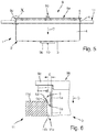
- FIG. 5 shows an intermediate state during installation of the sink according to FIG. 1 or FIGS. 2 a through 2 d according to the inventive method
- FIG. 6 shows a detail from FIG. 5 ;
- FIGS. 7 a through 7 d show successive method steps for completing the sink installation process.
- the sink according to the present invention is denoted by means of reference numeral 1 .
- Said sink 1 can—without limitation—be devised as a kitchen sink. It comprises a bowl 2 with a bottom wall 3 and a circumferential side wall 4 . At least one outlet opening, which cannot be seen in FIG. 1 , is located in said bottom wall 3 (cf. FIG. 2 b ).
- a circumferential rim 5 is located at an upper edge of said bowl 2 around an outside thereof, as can be readily seen from FIG. 1 . Said rim 5 extends outwardly from said side wall 4 by an extent (cf. e.g. FIG. 6 ).
- the sink 1 comprises a number of resilient clamping elements 6 arranged on the outside of said bowl 2 adjacent said rim 5 .
- said clamping elements 6 are shown in a free or uncompressed state, in which they extend outwardly beyond the extent of said rim 5 (refer to FIGS. 5 and 6 for more details)
- the clamping elements 6 are devised for providing, in a loaded or compressed state thereof, a clamping force directed outwardly from said side wall 4 , for holding the sink in a corresponding worktop cut-out, as will be explained in more detail below.
- a value of said extent E can be comprised between 2.5 mm and 6 mm, preferably between 2.5 mm and 5 mm, and more preferably equals about 4 mm.
- the clamping elements 6 can comprise at least one spring element which is hook-shaped in cross section, with a first leg 6 a extending essentially parallel to said side wall 4 and preferably downwardly from said rim 5 , a second leg 6 b extending outwardly from said first leg 6 a and from said side wall 4 , and a third leg 6 c extending outwardly from second leg 6 b and from said side wall 4 as well as parallel to said first leg 6 a , in said free or uncompressed state of the clamping elements 6 , as shown in FIG. 6 . Furthermore, said third leg 6 c at least partly overlaps with said first leg 6 a . A free end portion of said third leg 6 c is angled outwardly from said side wall 4 , as shown at reference numeral 6 d.
- the rim 5 is configured in solid material for increased mechanical strength. Alternatively, it could be configured by outward and downward bending of the side wall 4 material.
- the clamping elements 6 are compressible inwardly toward the side wall 4 to an extent that they do no longer extend outwardly beyond said extent E of the rim 5 . This enables easy installation of the sink 1 from above a worktop, as will be explained in detail below.
- a clamping force per unit length of the side wall 4 is essentially evenly distributed around the sink, by adapting the number of the clamping elements 6 .
- all of the clamping elements 6 are essentially identical; however, more clamping elements have been placed along the longer side walls of the rectangular sink 1 , thus enabling centering of the sink 1 within a worktop cut-out.
- the number of clamping elements 6 at opposing side walls 4 of the sink 1 should be identical, which cannot be seen in FIG. 1 .
- a bead 8 of an adhesive sealing material is placed around the rim 5 , which adhesive sealing material can be—without limitation—a silicone material.
- adhesive sealing material can be—without limitation—a silicone material.
- said bead 8 is placed around the entire periphery of the rim 5 around the sink 1 , more preferably with a bead diameter of approx. 7 mm.
- FIGS. 2 a through 2 d show the sink 1 of FIG. 1 (without bead 8 ) and its interaction with a special installation device denoted by reference numeral 9 .
- the installation device 9 comprises and installing jig 9 a and a so-called jig counterpart or counterpart 9 b .
- the installing jig 9 a can be best seen in FIGS. 2 a and 2 c
- the counterpart 9 b can be best seen in FIGS. 2 b and 2 d .
- the installing jig 9 a and its counterpart 9 b can be made—for instance—in plastic or wood-composite material, without limitation.
- the installing jig 9 a has a flat, sheet-like configuration of overall rectangular shape with circumferentially protruding flaps 9 c and grip openings 9 d , which are located in vicinity of an edge portion of the installing jig 9 a . Further comprised are two connecting openings 9 e which are located near a center of the installing jig 9 a .
- the installing jig 9 a can be placed on top of the sink 1 , so that it rests on an upper edge or upper face of the rim, while said flaps 9 c protrude outwardly from the sink 1 with respect to the rim.
- the location of each flap 9 c corresponds to the location of a clamping element 6 .
- the square-shaped counterpart 9 b is placed over an outlet opening 3 a of sink bottom wall 3 .
- the overall dimensions of counterpart 9 b are devised such that it completely covers said outlet opening 3 a , without passing therethrough.
- sink 1 has an edge contour 3 b around said opening 3 b , which contour 3 b corresponds to a shape of the counterpart 9 b in form fitting manner.
- said counterpart 9 b has a central opening 9 f which can be devised as a threaded bore.
- FIG. 2 c illustrates how a screw (or other connector) 10 can be inserted through opening 9 e for connecting the installing jig 9 a and its counterpart 9 b mutually and in connection with the sink 1 (cf. FIG. 2 d ).
- the screw 10 is screwed into threaded bore 9 f of counterpart 9 b .
- the installing jig 9 a and its counterpart 9 b are securely and removably attached to sink 1 , as shown in FIG. 2 d .
- Sink 1 can then be manipulated by simply engaging grip openings 9 d.
- FIG. 3 shows a worktop 11 having an essentially rectangular cut-out 11 a , which cut-out 11 a is intended to be fitted with a sink 1 as described above in connection with FIGS. 1 and 2 a through 2 d as well as FIG. 6 .
- the cut-out 11 a is made larger in dimension than an area circumscribed by said rim but smaller than an envelope around said clamping elements in their uncompressed state while defining a cut-out side wall 11 b extending essentially at right angles with respect to an upper and lower surface of said worktop.
- Worktop 11 can be made of wood, metal, stone or any other suitable (composite) material. It should be noted that the side wall 11 b of cut-out 11 a needs not to be polished or otherwise treated when installing sink 1 as described above by using an installation method according to the present invention.
- worktop 11 has been provided, adjacent a contour of cut-out 11 a , with a removable protective cover 11 c made from strips of a suitable tape material.
- sink 1 with installation device 9 and bead 8 (not shown; cf. FIG. 1 ) is inserted downwardly (arrow D) in the cut-out (cf. FIG. 3, 4 ) of worktop 11 .
- the clamping elements 6 are compressed by interaction with the cut-out side wall 11 b , thus generating a force for holding sink 1 within the cut-out 11 a .
- sink 1 is pushed downwardly D until the flaps 9 c of installing jig 9 a make contact with an upper surface 11 d of worktop 11 .
- edge 5 of sink 1 is located within cut-out 11 a opposite side wall 11 b , and sealing material of bead 8 is located between said side wall 11 b and said rim 5 for sealing a gap therebetween and for durably holding the sink after setting or curing of the adhesive sealing material, while further protecting side wall 11 b.
- FIG. 7 a shows the state of the installation after said contact between installing jig 9 a and worktop 11 .
- An upper face or upper edge (not shown) of the sink rim is now coplanar with worktop upper surface 11 d.
- connector or screw 10 is removed from installation device 9 , thus separating installing jig 9 a and its counterpart 9 b .
- connector 10 has an abutment 10 a which comes into contact with installing jig 9 a (cf. FIG. 7 a ) for defining a maximum distance between connected installing jig 9 a and counterpart 9 b.
- the protective cover 11 is removed, thus achieving a complete workplace according to an aspect of the present invention.
- the clamping elements will hold the sink in position until the sealing material has dried (set or cured).
- the sealing material (silicone) could be applied with a bead diameter of approximately 7 mm all around the sink rim.
- said screw 10 can be devised with an M8 thread. The same holds for the threaded bore 9 f of counterpart 9 b.
- cut-out 10 a should correspond to a sink bowl length+2 mm and to a sink bowl width+2 mm, respectively.
- any concrete dimensions will also depend on the respective dimensions of clamping elements 6 and rim 5 (extent E) according to FIG. 6 .
- protective cover 11 c according to FIG. 4 could be applied with a respective width of 20 through 30 mm, without limitation.
Landscapes
- Engineering & Computer Science (AREA)
- Environmental & Geological Engineering (AREA)
- Health & Medical Sciences (AREA)
- Life Sciences & Earth Sciences (AREA)
- Hydrology & Water Resources (AREA)
- Public Health (AREA)
- Water Supply & Treatment (AREA)
- Sink And Installation For Waste Water (AREA)
- Details Of Rigid Or Semi-Rigid Containers (AREA)
Priority Applications (1)
| Application Number | Priority Date | Filing Date | Title |
|---|---|---|---|
| US15/662,863 US10550558B2 (en) | 2016-07-28 | 2017-07-28 | Sink and method of installing same |
Applications Claiming Priority (5)
| Application Number | Priority Date | Filing Date | Title |
|---|---|---|---|
| EP16181575.8 | 2016-07-28 | ||
| EP16181575.8A EP3276093A1 (de) | 2016-07-28 | 2016-07-28 | Spülbecken und verfahren zur installation davon |
| EP16181575 | 2016-07-28 | ||
| US201662371408P | 2016-08-05 | 2016-08-05 | |
| US15/662,863 US10550558B2 (en) | 2016-07-28 | 2017-07-28 | Sink and method of installing same |
Publications (2)
| Publication Number | Publication Date |
|---|---|
| US20180030703A1 US20180030703A1 (en) | 2018-02-01 |
| US10550558B2 true US10550558B2 (en) | 2020-02-04 |
Family
ID=56555250
Family Applications (1)
| Application Number | Title | Priority Date | Filing Date |
|---|---|---|---|
| US15/662,863 Expired - Fee Related US10550558B2 (en) | 2016-07-28 | 2017-07-28 | Sink and method of installing same |
Country Status (7)
| Country | Link |
|---|---|
| US (1) | US10550558B2 (de) |
| EP (1) | EP3276093A1 (de) |
| CN (1) | CN107663879A (de) |
| CA (1) | CA3027863A1 (de) |
| CH (1) | CH712681B1 (de) |
| HK (1) | HK1243747A1 (de) |
| WO (1) | WO2018019581A1 (de) |
Cited By (2)
| Publication number | Priority date | Publication date | Assignee | Title |
|---|---|---|---|---|
| WO2022187345A1 (en) * | 2021-03-02 | 2022-09-09 | V-T Industries Inc. | Systems and methods for modular sink with rapid installation |
| US11454011B2 (en) * | 2018-08-15 | 2022-09-27 | Franke Technology And Trademark Ltd | Connecting element for fastening a sink to a worktop |
Families Citing this family (8)
| Publication number | Priority date | Publication date | Assignee | Title |
|---|---|---|---|---|
| CN108842877B (zh) * | 2018-07-02 | 2020-02-11 | 安徽思源三轻智能制造有限公司 | 一种密封性能好的盥洗池及该种盥洗池主体的安装方法 |
| CN110847306B (zh) | 2018-08-21 | 2022-09-27 | 科勒公司 | 带有可互换面的前裙板水槽 |
| USD872243S1 (en) | 2018-08-27 | 2020-01-07 | Kohler Co. | Apron front sink |
| US11324318B2 (en) | 2018-10-04 | 2022-05-10 | Kohler Co. | Apron front sink panel assembly |
| US12123182B2 (en) | 2020-01-24 | 2024-10-22 | Kohler Co. | Method of manufacturing a sink system |
| US11781302B2 (en) | 2020-01-24 | 2023-10-10 | Kohler Co. | Sink having removable apron and accessory systems |
| USD952808S1 (en) | 2020-01-24 | 2022-05-24 | Kohler Co. | Sink |
| US12066179B2 (en) | 2020-06-29 | 2024-08-20 | Kohler Co. | Sink lighting system |
Citations (19)
| Publication number | Priority date | Publication date | Assignee | Title |
|---|---|---|---|---|
| US2080573A (en) * | 1935-11-16 | 1937-05-18 | George L Curtis | Sink and counter top construction |
| US2858548A (en) * | 1957-04-05 | 1958-11-04 | Harold K Switzer | Sink strip assembly |
| US3071780A (en) * | 1960-12-27 | 1963-01-08 | Jr George A Lyon | Sink held in place by biting retaining fingers |
| US3585657A (en) * | 1968-12-02 | 1971-06-22 | Alfred C Jensen | Spring clip appliance mounting in a counter opening |
| EP0307825A1 (de) * | 1987-09-15 | 1989-03-22 | Schock & Co. GmbH | Gestell mit eingesetztem Formteil |
| AT393075B (de) | 1989-10-25 | 1991-08-12 | Oespag Oesterr Sanitaer | Befestigungselement fuer waschbecken |
| US5177853A (en) | 1992-04-20 | 1993-01-12 | Herook John T | Garbage disposal flange assembly tool |
| CN1299430A (zh) | 1998-05-07 | 2001-06-13 | 克利斯蒂安·林巴赫 | 用于家俱特别是用于浴室或厨房家俱的将盆体装入一接纳平面的方法和由此获得的整体组件 |
| US6591468B1 (en) | 2001-10-12 | 2003-07-15 | John Q. Douglas | Sink lifting device |
| US6782593B1 (en) * | 2003-02-18 | 2004-08-31 | Merhav-Designer Building Products Ltd. | Kitchen sink |
| US6793190B2 (en) * | 2001-10-23 | 2004-09-21 | Elkay Manufacturing Company | Retainer clip for mounting sink to countertop |
| US20050039254A1 (en) | 2003-08-18 | 2005-02-24 | Joseph Brown | Sink clip |
| EP1772566A2 (de) | 2005-10-05 | 2007-04-11 | Niro-Plan Ag | Küchen-Einbauteil |
| CA2622792A1 (en) | 2008-03-27 | 2009-09-27 | Dilpreet Joura | Stainless steel sinks mounting clip with self locking |
| US8070562B1 (en) | 2004-11-05 | 2011-12-06 | Daren Paul Murrer | Granite finishing tools |
| US20130019443A1 (en) | 2011-07-19 | 2013-01-24 | Clinton Gomes | Recessed or Self-Rimming Sink Support Tool |
| EP2884013A1 (de) | 2013-12-10 | 2015-06-17 | Mehmet Hocaoglu | Nahtloses untermontiertes edelstahl-spülbeckensystem |
| CN104895163A (zh) | 2015-05-28 | 2015-09-09 | 南京皓威机械有限公司 | 一种铝合金水槽 |
| US9803347B2 (en) * | 2013-08-29 | 2017-10-31 | Mehmet Hocaoglu | Seamless undermount stainless steel sink system |
Family Cites Families (1)
| Publication number | Priority date | Publication date | Assignee | Title |
|---|---|---|---|---|
| AT75U1 (de) * | 1994-02-08 | 1995-01-25 | Reitterer Andreas Reitterer An | Handpresse fuer knoblauch |
-
2016
- 2016-07-28 EP EP16181575.8A patent/EP3276093A1/de not_active Withdrawn
- 2016-08-11 CH CH01033/16A patent/CH712681B1/de not_active IP Right Cessation
-
2017
- 2017-07-12 WO PCT/EP2017/067499 patent/WO2018019581A1/en not_active Ceased
- 2017-07-12 CA CA3027863A patent/CA3027863A1/en not_active Abandoned
- 2017-07-18 CN CN201710584156.2A patent/CN107663879A/zh active Pending
- 2017-07-28 US US15/662,863 patent/US10550558B2/en not_active Expired - Fee Related
-
2018
- 2018-03-08 HK HK18103307.2A patent/HK1243747A1/zh unknown
Patent Citations (22)
| Publication number | Priority date | Publication date | Assignee | Title |
|---|---|---|---|---|
| US2080573A (en) * | 1935-11-16 | 1937-05-18 | George L Curtis | Sink and counter top construction |
| US2858548A (en) * | 1957-04-05 | 1958-11-04 | Harold K Switzer | Sink strip assembly |
| US3071780A (en) * | 1960-12-27 | 1963-01-08 | Jr George A Lyon | Sink held in place by biting retaining fingers |
| US3585657A (en) * | 1968-12-02 | 1971-06-22 | Alfred C Jensen | Spring clip appliance mounting in a counter opening |
| EP0307825A1 (de) * | 1987-09-15 | 1989-03-22 | Schock & Co. GmbH | Gestell mit eingesetztem Formteil |
| AT393075B (de) | 1989-10-25 | 1991-08-12 | Oespag Oesterr Sanitaer | Befestigungselement fuer waschbecken |
| US5177853A (en) | 1992-04-20 | 1993-01-12 | Herook John T | Garbage disposal flange assembly tool |
| CN1299430A (zh) | 1998-05-07 | 2001-06-13 | 克利斯蒂安·林巴赫 | 用于家俱特别是用于浴室或厨房家俱的将盆体装入一接纳平面的方法和由此获得的整体组件 |
| US6311345B1 (en) | 1998-05-07 | 2001-11-06 | Christian Limbach | Method for incorporating a basin in a receiving plane, resulting monobloc assembly for furniture in particular bathroom or kitchen furniture |
| US6591468B1 (en) | 2001-10-12 | 2003-07-15 | John Q. Douglas | Sink lifting device |
| US6793190B2 (en) * | 2001-10-23 | 2004-09-21 | Elkay Manufacturing Company | Retainer clip for mounting sink to countertop |
| US6782593B1 (en) * | 2003-02-18 | 2004-08-31 | Merhav-Designer Building Products Ltd. | Kitchen sink |
| US20050039254A1 (en) | 2003-08-18 | 2005-02-24 | Joseph Brown | Sink clip |
| US8070562B1 (en) | 2004-11-05 | 2011-12-06 | Daren Paul Murrer | Granite finishing tools |
| EP1772566A2 (de) | 2005-10-05 | 2007-04-11 | Niro-Plan Ag | Küchen-Einbauteil |
| US20070151019A1 (en) | 2005-10-05 | 2007-07-05 | Niro-Plan Ag | Kitchen mounting part |
| US7523511B2 (en) * | 2005-10-05 | 2009-04-28 | Niro-Plan Ag | Kitchen mounting part |
| CA2622792A1 (en) | 2008-03-27 | 2009-09-27 | Dilpreet Joura | Stainless steel sinks mounting clip with self locking |
| US20130019443A1 (en) | 2011-07-19 | 2013-01-24 | Clinton Gomes | Recessed or Self-Rimming Sink Support Tool |
| US9803347B2 (en) * | 2013-08-29 | 2017-10-31 | Mehmet Hocaoglu | Seamless undermount stainless steel sink system |
| EP2884013A1 (de) | 2013-12-10 | 2015-06-17 | Mehmet Hocaoglu | Nahtloses untermontiertes edelstahl-spülbeckensystem |
| CN104895163A (zh) | 2015-05-28 | 2015-09-09 | 南京皓威机械有限公司 | 一种铝合金水槽 |
Non-Patent Citations (1)
| Title |
|---|
| Machine Translation of EP '825. Espacenet. (Year: 2019). * |
Cited By (3)
| Publication number | Priority date | Publication date | Assignee | Title |
|---|---|---|---|---|
| US11454011B2 (en) * | 2018-08-15 | 2022-09-27 | Franke Technology And Trademark Ltd | Connecting element for fastening a sink to a worktop |
| WO2022187345A1 (en) * | 2021-03-02 | 2022-09-09 | V-T Industries Inc. | Systems and methods for modular sink with rapid installation |
| US12385242B2 (en) | 2021-03-02 | 2025-08-12 | V-T Industries, Inc. | Systems and methods for modular sink with rapid installation |
Also Published As
| Publication number | Publication date |
|---|---|
| CA3027863A1 (en) | 2018-02-01 |
| CN107663879A (zh) | 2018-02-06 |
| EP3276093A1 (de) | 2018-01-31 |
| HK1243747A1 (zh) | 2018-07-20 |
| US20180030703A1 (en) | 2018-02-01 |
| WO2018019581A1 (en) | 2018-02-01 |
| CH712681B1 (de) | 2018-01-15 |
Similar Documents
| Publication | Publication Date | Title |
|---|---|---|
| US10550558B2 (en) | Sink and method of installing same | |
| ES2941544T3 (es) | Separador de baldosas | |
| US8720143B2 (en) | Tile spacer | |
| MX2007010219A (es) | Dispositivo de alineacion y nivelacion de losetas y metodos para usar el mismo. | |
| CN102149483B (zh) | 筛子固定装置 | |
| US10731360B2 (en) | Spacer for laying tiles, bricks and the like with the interposition of gaps | |
| US20200123751A1 (en) | Sink and method of installing same | |
| KR101558098B1 (ko) | 비철거식 개보수 전용 창호 | |
| US20150074902A1 (en) | Sink clip | |
| CN105640659B (zh) | 上部构造可拆卸的假牙装置及相关的螺丝 | |
| US10837211B2 (en) | Slip resistant glass hinge system | |
| CN105398499A (zh) | 密封塞 | |
| KR101626836B1 (ko) | 조립식 관 및 이의 조립방법 | |
| WO2019101293A1 (en) | Sink and method of installing same | |
| KR101978359B1 (ko) | 마루 시공용 마루굽틀 | |
| RU138668U1 (ru) | Устройство выравнивания горизонтальной и вертикальной поверхности | |
| KR101920424B1 (ko) | 타일용 코너비드 | |
| BE1030900B1 (nl) | Werkwijze voor het bevestigen van een paneel op een douchebak | |
| JP5639365B2 (ja) | 残存型枠パネル用の挿入具及びそれを用いたコンクリート型枠 | |
| KR101476589B1 (ko) | 건물바닥용 황동줄눈 지지장치 | |
| HK40011979A (en) | Sink and method of installing same | |
| RU2834638C1 (ru) | Выравниватель плиток | |
| EA039342B1 (ru) | Крепежное приспособление для укладки закрывающего стыки/пороги профилированного элемента и комплект, содержащий такое крепежное приспособление | |
| CN209824205U (zh) | 一种通信仪器的壳体结构 | |
| KR20240002056U (ko) | 건축용 단열재 고정 장치 |
Legal Events
| Date | Code | Title | Description |
|---|---|---|---|
| AS | Assignment |
Owner name: FRANKE TECHNOLOGY AND TRADEMARK LTD, SWITZERLAND Free format text: ASSIGNMENT OF ASSIGNORS INTEREST;ASSIGNORS:CAGLIARI, ALESSANDRO;BOMATTER, CHRISTIAN W.;NEESER, ROLF;SIGNING DATES FROM 20170718 TO 20170721;REEL/FRAME:043132/0262 |
|
| STPP | Information on status: patent application and granting procedure in general |
Free format text: NON FINAL ACTION MAILED |
|
| STPP | Information on status: patent application and granting procedure in general |
Free format text: RESPONSE TO NON-FINAL OFFICE ACTION ENTERED AND FORWARDED TO EXAMINER |
|
| STPP | Information on status: patent application and granting procedure in general |
Free format text: FINAL REJECTION MAILED |
|
| STPP | Information on status: patent application and granting procedure in general |
Free format text: DOCKETED NEW CASE - READY FOR EXAMINATION |
|
| STPP | Information on status: patent application and granting procedure in general |
Free format text: NOTICE OF ALLOWANCE MAILED -- APPLICATION RECEIVED IN OFFICE OF PUBLICATIONS |
|
| STPP | Information on status: patent application and granting procedure in general |
Free format text: PUBLICATIONS -- ISSUE FEE PAYMENT VERIFIED |
|
| STCF | Information on status: patent grant |
Free format text: PATENTED CASE |
|
| FEPP | Fee payment procedure |
Free format text: MAINTENANCE FEE REMINDER MAILED (ORIGINAL EVENT CODE: REM.); ENTITY STATUS OF PATENT OWNER: LARGE ENTITY |
|
| LAPS | Lapse for failure to pay maintenance fees |
Free format text: PATENT EXPIRED FOR FAILURE TO PAY MAINTENANCE FEES (ORIGINAL EVENT CODE: EXP.); ENTITY STATUS OF PATENT OWNER: LARGE ENTITY |
|
| STCH | Information on status: patent discontinuation |
Free format text: PATENT EXPIRED DUE TO NONPAYMENT OF MAINTENANCE FEES UNDER 37 CFR 1.362 |
|
| FP | Lapsed due to failure to pay maintenance fee |
Effective date: 20240204 |