US10550577B2 - Face mounting system - Google Patents
Face mounting system Download PDFInfo
- Publication number
- US10550577B2 US10550577B2 US15/679,076 US201715679076A US10550577B2 US 10550577 B2 US10550577 B2 US 10550577B2 US 201715679076 A US201715679076 A US 201715679076A US 10550577 B2 US10550577 B2 US 10550577B2
- Authority
- US
- United States
- Prior art keywords
- panel
- elongate
- wall
- protrusion
- flat surface
- Prior art date
- Legal status (The legal status is an assumption and is not a legal conclusion. Google has not performed a legal analysis and makes no representation as to the accuracy of the status listed.)
- Active
Links
- 238000000034 method Methods 0.000 claims description 13
- 239000004033 plastic Substances 0.000 claims description 8
- 229920003023 plastic Polymers 0.000 claims description 8
- XAGFODPZIPBFFR-UHFFFAOYSA-N aluminium Chemical compound [Al] XAGFODPZIPBFFR-UHFFFAOYSA-N 0.000 claims description 4
- 229910052782 aluminium Inorganic materials 0.000 claims description 4
- 239000000463 material Substances 0.000 description 9
- 125000006850 spacer group Chemical group 0.000 description 8
- 238000007373 indentation Methods 0.000 description 3
- 238000003780 insertion Methods 0.000 description 3
- 230000037431 insertion Effects 0.000 description 3
- 239000004676 acrylonitrile butadiene styrene Substances 0.000 description 2
- XECAHXYUAAWDEL-UHFFFAOYSA-N acrylonitrile butadiene styrene Chemical compound C=CC=C.C=CC#N.C=CC1=CC=CC=C1 XECAHXYUAAWDEL-UHFFFAOYSA-N 0.000 description 1
- 229920000122 acrylonitrile butadiene styrene Polymers 0.000 description 1
- 230000001154 acute effect Effects 0.000 description 1
- 238000005452 bending Methods 0.000 description 1
- 230000003247 decreasing effect Effects 0.000 description 1
- 230000007812 deficiency Effects 0.000 description 1
- 238000006073 displacement reaction Methods 0.000 description 1
- 239000003000 extruded plastic Substances 0.000 description 1
- 238000009434 installation Methods 0.000 description 1
- 238000000465 moulding Methods 0.000 description 1
- 238000010422 painting Methods 0.000 description 1
- 210000002105 tongue Anatomy 0.000 description 1
- 230000003313 weakening effect Effects 0.000 description 1
Images



Classifications
-
- E—FIXED CONSTRUCTIONS
- E04—BUILDING
- E04F—FINISHING WORK ON BUILDINGS, e.g. STAIRS, FLOORS
- E04F13/00—Coverings or linings, e.g. for walls or ceilings
- E04F13/07—Coverings or linings, e.g. for walls or ceilings composed of covering or lining elements; Sub-structures therefor; Fastening means therefor
- E04F13/08—Coverings or linings, e.g. for walls or ceilings composed of covering or lining elements; Sub-structures therefor; Fastening means therefor composed of a plurality of similar covering or lining elements
- E04F13/0801—Separate fastening elements
- E04F13/0803—Separate fastening elements with load-supporting elongated furring elements between wall and covering elements
-
- E—FIXED CONSTRUCTIONS
- E04—BUILDING
- E04F—FINISHING WORK ON BUILDINGS, e.g. STAIRS, FLOORS
- E04F13/00—Coverings or linings, e.g. for walls or ceilings
- E04F13/002—Coverings or linings, e.g. for walls or ceilings made of webs, e.g. of fabrics, or wallpaper, used as coverings or linings
-
- E—FIXED CONSTRUCTIONS
- E04—BUILDING
- E04F—FINISHING WORK ON BUILDINGS, e.g. STAIRS, FLOORS
- E04F13/00—Coverings or linings, e.g. for walls or ceilings
- E04F13/07—Coverings or linings, e.g. for walls or ceilings composed of covering or lining elements; Sub-structures therefor; Fastening means therefor
- E04F13/08—Coverings or linings, e.g. for walls or ceilings composed of covering or lining elements; Sub-structures therefor; Fastening means therefor composed of a plurality of similar covering or lining elements
- E04F13/0801—Separate fastening elements
- E04F13/0803—Separate fastening elements with load-supporting elongated furring elements between wall and covering elements
- E04F13/081—Separate fastening elements with load-supporting elongated furring elements between wall and covering elements with additional fastening elements between furring elements and covering elements
- E04F13/0816—Separate fastening elements with load-supporting elongated furring elements between wall and covering elements with additional fastening elements between furring elements and covering elements the additional fastening elements extending into the back side of the covering elements
-
- E—FIXED CONSTRUCTIONS
- E04—BUILDING
- E04F—FINISHING WORK ON BUILDINGS, e.g. STAIRS, FLOORS
- E04F13/00—Coverings or linings, e.g. for walls or ceilings
- E04F13/07—Coverings or linings, e.g. for walls or ceilings composed of covering or lining elements; Sub-structures therefor; Fastening means therefor
- E04F13/08—Coverings or linings, e.g. for walls or ceilings composed of covering or lining elements; Sub-structures therefor; Fastening means therefor composed of a plurality of similar covering or lining elements
- E04F13/0871—Coverings or linings, e.g. for walls or ceilings composed of covering or lining elements; Sub-structures therefor; Fastening means therefor composed of a plurality of similar covering or lining elements having an ornamental or specially shaped visible surface
Definitions
- Wall panels may be mounted to walls and other flat surfaces to protect the wall and for aesthetic purposes.
- Wall panels may be mounted to walls and other flat surfaces to protect the wall and for aesthetic purposes.
- a face mounting system for mounting a plurality of wall panels to a wall surface of a wall is disclosed herein.
- the plurality of wall panels may be attached to the wall surface of the wall by way of a plurality of rails and clips.
- the rails and clips may have a protrusion and hooks that engage the protrusion respectively or vice versa.
- the rails may be attached to the wall surface.
- the clips may be attached to the panels. In this configuration, each one of the panels may be attached and removed from the wall one by one and in any order.
- a structure having a wall defining a flat surface with a face mounting system mounted on the flat surface of the wall is disclosed.
- the face mounting system may include a plurality of panels.
- the structure may comprise the wall; the plurality of panels, each panel being between 6′′ ⁇ 6′′ and 20′′ ⁇ 20′′ and having a thickness between 5/16′′ and 1′′, each panel defining front and back flat surfaces; a plurality of mounting rails having a length greater than 1 ⁇ 2 a width of the panel and greater than the width of the panel, the mounting rails attached to the flat surface of the wall, each mounting rail having at least one elongate protrusion; and a plurality of panel clips attached to the back surface of each of the panels, the clips each having opposed elongate hooks that are attached to the elongate protrusions of the mounting rails and any one of the panels being removable from the flat surface of the wall with a pulling force.
- the panels can be removed with a force perpendicular from the flat surface of the wall applied to the panel to be removed so that any one of the panels can be removed without removal of an adjacent panel.
- the perpendicular force may be plus or minus 25 degrees from 90 degrees with respect to the flat surface of the wall.
- the elongate protrusion may extends outward perpendicular to the flat surface and have a mirror image about a horizontal perpendicular plane so that the panel clips can be removed from or attached to the mounting rails by pulling the panel perpendicularly away from the flat surface or pushing the panel perpendicularly toward the flat surface.
- a structure having a wall defining a flat surface with a face mounting system mounted on the flat surface of the wall may include a plurality of panels.
- the structure may comprise the wall; the plurality of panels, each panel being between 6′′ ⁇ 6′′ and 20′′ ⁇ 20′′ and having a thickness between 5/16′′ and 1′′, each panel defining front and back flat surfaces; a plurality of panel clips greater than 1 ⁇ 2 a width of the panel and greater than the width of the panel, the panel clips attached to the flat surface of the wall, each panel clip having opposed elongate hooks; and a plurality of mounting rails attached to the back surface of each of the panels, the mounting rails each having at least one elongate protrusion that are attached to the opposed elongate hooks of the panel clips and any one of the panels being removable from the flat surface of the wall with a pulling force.
- the panel In attaching the panel to the wall, it is contemplated that only opposed elongate hooks are secured to the elongate protrusion and the panels can be removed with a force perpendicular from the flat surface applied to the panel to be removed so that any one of the panels can be removed without removal of an adjacent panel.
- the perpendicular force may be plus or minus 25 degrees from 90 degrees with respect to the flat surface of the wall.
- the elongate protrusion may extend toward and perpendicular to the flat surface and have a mirror image about a perpendicular plane so that the panel clips can be removed from or attached to the mounting rails by pulling the panel perpendicularly away from the flat surface or pushing the panel perpendicularly toward the flat surface.
- a method of installing a face mounting system to a wall may comprise the steps of attaching a first elongate rails to a flat surface of the wall, the first elongate rails having a first protrusion which is straight; aligning a second elongate rail having a second protrusion which is straight parallel to the first protrusion; attaching the second elongate rails to the flat surface of the wall while holding the alignment achieved during the aligning the second elongate rail step; aligning and attaching additional elongate rails to the flat surface of the wall so that protrusions of the additional elongate rails are parallel to the first and second protrusions of the first and second elongate rails; and attaching upper and lower clips to each panel of a plurality of panels, a distance between the upper and lower clips being equal to a distance between the first protrusion of the first elongate rail and the second protrusion of the second elongate rail so that the upper and lower clips
- the clips may have opposed hooks that latch onto the protrusion.
- the method may further comprise the step of attaching a suction cup with a handle to a front surface of the panel to hold the panel while pushing the panel toward the wall for attaching the upper and lower clips attached to the panel to corresponding rails attached to the flat surface of the wall.
- FIG. 1 illustrates a perspective view of a face mounting system of a plurality of wall panels mounted to a wall
- FIG. 2 illustrates a perspective view of a mid panel horizontal rail used to stabilize a middle area of a panel to the wall;
- FIG. 3 illustrates a first state in which a protrusion of a rail is inserted between hooks of a clip in order to engage the rail to the clip and the panel to the wall;
- FIG. 4 illustrates a second state in which the protrusion of the rail is further inserted between the hooks of the clip in order to engage the clip to the rail and the panel to the wall;
- FIG. 5 illustrates a third state in which the protrusion of the rail is even further inserted into the hooks of the clip in order to engage the clip to the rail and the panel to the wall;
- FIG. 6 illustrates a final state in which the protrusion of the rail is fully inserted into the hooks of the clip in order to engage the clip to the rail and the panel to the wall;
- FIG. 7 illustrates a horizontal rail of a first embodiment
- FIG. 8 illustrates the clip
- FIG. 9 illustrates attachment of the panel adjacent to a ceiling
- FIG. 10 illustrates a horizontal joint for attaching upper and lower panels to the wall
- FIG. 11 illustrates a vertical edge detail
- FIG. 12 illustrates a vertical joint detail
- FIG. 13 illustrates a bottom rail for mounting the panel to the wall
- FIG. 14 illustrates a first embodiment of an outside corner
- FIG. 15 illustrates a second embodiment of the outside corner
- FIG. 16 illustrates a third embodiment of the outside corner
- FIG. 17 illustrates a fourth embodiment of the outside corner
- FIG. 18 illustrates an inside corner
- FIG. 19 illustrates a mid wall clip
- FIG. 20 illustrates a wainscot edge
- FIG. 21 illustrates the clip
- FIG. 21A illustrates an enlarged view of hooks of the clip shown in FIG. 21 ;
- FIG. 22 illustrates a horizontal rail
- FIG. 22A is an enlarged view of the protrusion of the horizontal rail shown in FIG. 22 ;
- FIG. 23 illustrates top and bottom rails
- FIG. 24 illustrates a vertical joint detail
- FIG. 25 illustrates the mid wall clip
- FIG. 26 illustrates attachment of a thicker panel compared to the panel shown in FIG. 9 adjacent to a ceiling
- FIG. 27 illustrates a horizontal joint for attaching the thicker upper and lower panels to the wall
- FIG. 28 illustrates a vertical edge detail for the thicker panel
- FIG. 29 illustrates a vertical joint detail for the thicker panel
- FIG. 30 illustrates a bottom rail for mounting the thicker panel to the wall
- FIG. 31 illustrates the first embodiment of the outside corner for the thicker panel
- FIG. 32 illustrates the third embodiment of the outside corner for the thicker panel
- FIG. 33 illustrates the fourth embodiment of the outside corner for the thicker panel
- FIG. 34 illustrates an inside corner for the thicker panel
- FIG. 35 illustrates a mid wall clip for the thicker panel
- FIG. 36 illustrates a wainscot edge for the thicker panel
- FIG. 37 illustrates a second embodiment of the rail for the thicker panel
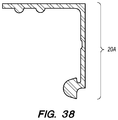
- FIG. 38 illustrates a second embodiment of the top and bottom rails for the thicker panel.
- FIG. 39 illustrates an alternative embodiment in which the clips and the rails are attached to the wall and the panels, respectively.
- the face mounting system 10 is mounted to a wall 12 to provide for aesthetic improvements over the bare wall 12 and also to protect a wall surface 14 .
- the face mounting system may include a plurality of horizontal rails 16 , 18 , 20 (see FIGS. 7, 10, 13 ) attached to the wall 12 .
- the face mounting system 10 may also include a plurality of clips 22 (see FIG. 8 ) attached to a plurality of panels 24 so that when the clips 22 are attached to the horizontal rails 16 , 18 , 20 , the panels 24 are mounted to the wall 12 .
- the horizontal rails 16 , 18 , 20 may have a protrusion 26 that perpendicularly extends away from the wall surface 14 of the wall 12 when the horizontal rails 16 , 18 , 20 are attached to the wall surface 14 .
- the clips 22 may have opposed hooks 28 that can engage over the protrusions 26 of the horizontal rails 16 , 18 , 20 .
- the opposed hooks 28 have an inner gap 30 (see FIG. 8 ) which is slightly smaller than an outer width 32 (see FIG. 7 ) of the protrusion 26 .
- the hooks 28 are formed so that they can be spread apart as the protrusion 26 is being pushed into a cavity 34 defined by the hooks 28 . In doing so, the panels 24 are being mounted to the wall 12 one at a time and in any order. Additionally, the hooks 28 can be spread apart to remove the panels 24 from the wall 12 .
- the panels 24 may be removed one at a time and in any order.
- FIG. 1 the face mounting system 10 is illustratively shown being mounted to the wall 12 having various features including an inside corner 36 , an outside corner 38 , a vertical free edge 40 , a window 42 , a door 44 , a bottom edge 46 , a top edge 48 , and a wainscot edge 50 .
- FIGS. 9-20 illustrate how a 3 ⁇ 8 inch thick panel 24 may be mounted to the wall 12
- FIGS. 26-36 illustrate how a 3 ⁇ 4 inch thick 52 panel 24 a may be mounted to the wall 12 .
- FIGS. 21-23 illustrate the clips 22 and rail 18 , 20 , and more particularly, the hooks 28 and the protrusion 26 .
- FIGS. 37 and 38 illustrate variants of the rails 18 a , 20 a when mounting a thicker panel 24 .
- FIG. 19 also illustrates the mid panel horizontal rail 16 and clip 22 for mounting the panel 24 to the wall 12 .
- FIGS. 3-6 illustrate the progression of the process of inserting the protrusion 26 of the horizontal rail 16 to the hooks 28 of the clip 22 .
- the protrusion 26 may have a bulbous front side 54 .
- the front side 54 although being shown as being bulbous may have other configurations including but not limited to two flat sides 56 shaped into an acute angle (e.g. triangularly shaped).
- the front side 54 of the protrusion 26 may have opposed flat portions 56 that form an angle 58 with each other between 25° and 80° but is preferably 70°.
- the protrusions 26 may be symmetrical about a horizontal plane 60 .
- An apex portion 62 may have an exterior surface defined by a radius 64 .
- the radius 64 may be 0.120 inches.
- the protrusion 26 may also have the opposed flat portions 56 that contact the hooks 28 and spread open the hooks 28 as shown by the progression shown in FIGS. 3-6 .
- the opposed bottom edges 66 may have a radius 68 .
- the radius 68 may be 0.013 inches.
- One side of the protrusion 60 may have a base 70 that is connected to the protrusion 26 with a neck portion 72 .
- the neck portion 72 may have an inner radius and a gap 74 .
- the gap 74 may be about 0.0255 inches.
- the opposed bottom edges 66 may have the same radius or different radius.
- the bottom edge 66 on the side of the base 70 may have a radius of 0.013 inches whereas the opposed bottom edge 66 on the side opposite of the base 70 may have a radius of 0.012 inches.
- the protrusion 26 described in relation to FIG. 22A may be replicated on the horizontal rails 16 , 18 , 20 .
- a width 75 of the protrusion may be 0.282 inches. The width 75 may be slightly greater than an internal gap 78 (see FIG. 21A ) so that the hooks 28 can latch onto the protrusion 26 .
- the hooks 28 of the clips 22 are shown.
- the hooks 28 may also be symmetrical about horizontal plane 80 .
- the hooks 28 may be mirror configurations to each other.
- the hooks 28 may have a centerline 82 .
- the centerline 82 may be angularly offset from the horizontal plane 80 by angle 84 .
- the angle 84 may be 35.5°.
- the hooks 28 may also define a length from an innermost point 86 to a central rotating axis 88 of the hook 28 .
- the length 91 may be about 0.076 inches.
- a thickness 90 of the hooks 28 may be sufficient so that the hooks 28 are generally rigid or have less displacement compared to neck portion 92 that connects the hook 28 to the base 94 .
- the neck portion 92 may have a thickness 96 of between 0.010 inch and 0.002 inch and be preferably 0.005 inches. As the length 91 increases, the thickness 96 may increase due to the increased leverage of the increased distance 91 . In turn, the length of the clip 22 may be decreased. The length 98 may be about 23 ⁇ 8′′ for the existing configuration which provides sufficient amount of material at the neck portion 92 so that the hooks 98 are not torn off when the hooks 28 are spread open to latch on to the protrusion 26 .
- the hooks 28 may have a radiused surface 100 which defines the innermost point 86 .
- the protrusion 26 may contact the radiused surface 100 as the protrusion 26 is being inserted into the cavity 34 .
- the radius portion 100 contacts the apex portion 62 and more preferably the opposed flat portion of 56 of the protrusion 26 . Because of the angled surfaces of the opposed flat portions 56 , the hooks 28 are spread open as shown in FIGS. 4 and 5 . At some point during insertion, the protrusion will slide on and contact the innermost point 86 for at least a portion of the insertion process or throughout the entire insertion process.
- the radiused surface 100 is at least partially behind the protrusion 26 in order to hold the protrusion 26 inside of the cavity 34 .
- the exterior configuration of the protrusion 26 may have a slightly smaller footprint compared to an interior surface of the cavity 34 so that the protrusion 26 can slightly wiggle inside of the cavity 34 by about one or two thousandth of an inch.
- the protrusion 26 may be held snugly within the cavity 34 defined by the hooks by wedging one of the hooks 28 into the gap 74 . That hook 28 may fill up the gap 74 to remove any play or wiggle room between the protrusion 26 and the cavity 34 .
- the hook 28 may have a hook distance 106 defined by two parallel lines 102 , 104 .
- the line 102 being aligned to a distal most end of the hook 28 that is wedged into the gap 74 .
- the line 104 is defined by an interior flat surface 108 of the hook 28 .
- the distal most end of the hook 28 that intersects line 102 may contact the base 70 of the rail 16 , 18 , 20 and the radiused surface 100 contacts the opposed bottom edges 66 of the protrusion 26 .
- the hooks 28 are allowed or can spread apart because of the relief provided by opposed grooves 110 on each of the hooks 28 to help neck down the neck portion 92 of the hooks 28 .
- the hooks 28 can be spread apart because of the material from which the hooks 28 are fabricated.
- the clips 22 may be fabricated from a plastic material such as acrylonitrile butadiene styrene (ABS) which is strong and the hooks 28 will not break off due to the bending stresses imposed on the clips 22 /hooks 28 .
- ABS acrylonitrile butadiene styrene
- the hooks 28 being a part of the clips 22 means that the hooks may be fabricated from a plastic material.
- the plastic material also has a memory in that once the hooks 28 are spread apart, the hooks 28 go back to its original position.
- the plastic material should be selected so as to allow the repeated mounting of the clips 22 to the rails and removal without significantly weakening the hooks 28 ability to secure the panel to the wall.
- the plastic material should be selected so as to allow the mounting and removal of the clips 22 to the rails between 20 cycles to 1000 cycles and preferably around 100 cycles.
- the plurality of panels may be mounted to the wall 12 .
- the panels may be arranged in aligned columns and rows.
- the panels 24 may be offset either horizontally or vertically.
- the panels 24 are shown as being rectangular or square. However, it is also contemplated panels 24 may be uniquely shaped and the plurality of panels 24 need not cover the entire wall 12 .
- a single panel 24 may be connected or mounted to the wall 12 at any position by attaching the rail to the wall 12 and the clip 22 to the panel or vice versa.
- the horizontal rails 16 , 18 , 20 and the clip 22 may be utilized to mount other objects to the wall 12 including but not limited to objects, paintings, pictures, frames, artwork.
- FIG. 1 illustrates panels positioned on the wall 12 adjacent to various features including but not limited to a floor 112 , the inside corner 36 , the outside corner 38 , a ceiling 114 , the wainscot edge 50 , an open edge 40 , the door 44 , and the window 42 .
- Various cross-sections are taken and shown in FIGS. 9-20 to illustrate how the rails 16 , 18 , 20 and the clips 22 as well as other components are used to mount the panels 24 to the wall 12 .
- the panels 24 as shown in FIG. 1 are square or rectangularly shape.
- Each of the four clips 22 may be positioned at or near the four corners of the panel 24 .
- the two clips 22 that are positioned at the upper corners of the panel 24 may be horizontally aligned to each other so that their 22 protrusions 26 are horizontally aligned to each other.
- the two clips that are positioned at the lower corners of the panel 24 may be horizontally aligned to each other as well in that the cavities 34 are horizontally aligned.
- the wall surface 14 may have a plurality of rails 16 , 18 , 20 that are aligned horizontally and mounted to the wall surface 14 .
- the two clips that are positioned at the upper corners of the panel 24 may be mounted to the same rail 16 , 18 or 20 .
- the two clips that are positioned at the lower corners of the panel 24 may be mounted to a different rail than the rail that is connected to the clips positioned at the upper corners of the panel 24 but the same rail is connected to the two clips that are positioned at the lower corners of the panel 24 .
- the two clips at the upper corners of the panel 24 may be attached to one of the rails 16 , 18 , 20 and the two clips 22 at the lower corners of the panel 24 are attached to another one of the rails 16 , 18 , 20 .
- the panel 24 is attached to the wall 12 right below the ceiling 114 .
- the rail 20 shown in FIG. 23 is mounted to the wall 12 .
- a flange 118 butts up against the ceiling 114 .
- a back surface 120 of the base of the rail 20 contacts the wall surface 14 .
- the base of the rail 20 may have an indentation 122 along its longitudinal length.
- the indentation 122 may be used to indicate to an installer where a screw 124 should be located with respect to the base of the rail 20 .
- the other rails 16 , 18 may also have the indentation 122 which also locates where the screw 124 should be located.
- Clips 22 may be extruded plastic.
- the plastic material may be ABS and provided in various lengths including but not limited to a length shorter than the width of the panel 24 , between 2 to 6 inches and preferably 4 inches.
- the horizontal rails 16 , 18 , 20 may be extruded aluminum and provided in various lengths including but not limited to a length shorter than the width of the panel 24 , 2 feet long, 4 feet long, 6 feet long, 8 feet long, 10 feet long, 12 feet long or longer or any increments of 1 foot.
- the clips 22 are preferably 23 ⁇ 8′′ long.
- the flange 118 may also have a spacer 126 that contacts an edge of the panel 24 .
- the panel 24 may be secured to the wall 12 by inserting the protrusion 26 between the hooks 28 of the clip 22 .
- the clip 22 may be secured to the panel 24 with screws 128 .
- the panel 24 may have two clips 22 at the same horizontal elevation so that two clips 22 are secured to the rail 20 .
- the panel 24 shown in FIG. 9 may also have two clips 22 at the lower corners of the panel 24 .
- FIG. 10 illustrates upper and lower panels 24 and the rail 18 that may be used to mount the two lower clips at the lower corners of the panel 24 shown in FIG. 9 .
- the rail 18 may be positioned and mounted to the wall 12 so that the two lower clips 22 mounted the lower corners of the panel 24 may be attached to the protrusion 26 .
- the protrusion 26 of the rail 20 may be inserted into the cavities 34 formed by the hooks 28 of the clips 22 simultaneously or it may be that one of the protrusions 26 are inserted into the cavities 34 of the corresponding clips 22 then the other one of the protrusions 26 is inserted into the cavities 34 of the other corresponding clips 22 , or vice versa.
- the panel 24 may be mounted near the floor 112 onto the wall 12 .
- the panel 24 is mounted to the wall 12 in the same manner that the panel 12 is mounted to the wall 12 adjacent the ceiling 114 .
- the panel 24 shown in FIG. 13 is gapped away from the floor 112 .
- the same may also be true for the panel 24 mounted adjacent the ceiling 114 .
- the gap between the rail 20 and the floor 112 may be empty to expose the wall surface 14 or may be filled with a base molding or other material if desired. Alternatively, the rail 20 may butt up against the floor.
- an extruded finishing piece 130 may be mounted to the wall 12 with screw 124 and be used to hide an edge of the panel 24 .
- the vertical joint 134 may have a finishing piece 136 .
- the finishing piece 136 may be an extruded aluminum piece that may be held in place by inserting the finishing piece 136 into a slot 138 formed on a side of the panel 24 .
- the finishing piece 136 is only inserted into a slot of one of the panels 24 but it is also contemplated that the finishing piece 136 may be formed with two tongues that are inserted into two corresponding grooves 140 of both panels 24 .
- the outside corner 38 may have one of three different types of finishing pieces 142 , 144 , 146 that may be secured to the outside corner of the wall 12 with screws 124 .
- the finishing piece 148 is used to stabilize the interior edges of the panels 24 .
- the clip 22 may be mounted to a middle of the panel 24 if needed. If the panel is sufficiently large then the clips 22 would be needed in order to stabilize the panel on the wall 12 . To this end, any one of the horizontal rails 16 , 18 , 20 may be mounted to the wall but in this instance rail 16 is shown.
- a rail 150 may be used to secure the upper edge portion of the panel 24 to the wall 12 .
- the rail 150 may be secured both to the wall 12 and the panel 24 with screws 124 , 128 .
- the rail 150 may be shimmed with a shim 152 so that the front surface 154 of the panel 24 appears to be in the same plane or level with the front surfaces 154 of the adjacent panels 24 .
- FIGS. 9-20 illustrate the mounting of a panel 24 having a thickness 52 of 3 ⁇ 8 of an inch.
- FIGS. 26-36 illustrate the mounting of a panel 24 a having a thickness 52 a of three quarters of an inch.
- the clips 22 and the horizontal rails 16 , 18 , 20 and optionally 150 as well as the other components described in relation to FIGS. 9-20 are the same as those in FIGS. 26-36 except as follows.
- the flange 118 a of the rail 20 a is slightly longer and has an additional spacer 126 .
- the screws 128 may be replaced with a self threading screw 156 .
- the rail 18 a shown in FIG. 27 may have an additional spacer 126 .
- the finishing piece 130 a may have a longer flange with an extra spacer 126 .
- the finishing piece 136 a may have additional spacers 126 that provide additional support to the adjacent edges of the panels 24 .
- the finishing pieces 141 a , 142 a , 144 a , 146 a may have an additional spacer to accommodate the thicker panels 24 a .
- the finishing piece 148 a shown in FIG. 34 may also have an additional spacer to accommodate the thicker panel 24 a .
- a cap 158 a attached to the rail 150 may have an additional spacer 126 .
- the panels may be attached to one wall at a time.
- the installer may install the rail 20 either at the top ceiling 114 or the floor 112 .
- the horizontal joint rail 18 , 18 a may be installed or mounted to the wall surface of the wall at a fixed distance away from the rail 20 .
- the fixed distance may be equal to a fixed distance between the clips 22 at the upper corners of the panel 24 and the clips 22 at the lower corners of the panel 24 .
- the protrusion 26 of the rail 20 may be set at a fixed distance to the protrusion 26 of the rail 18 , 18 a .
- the clip 22 may be set at the fixed distance between the clips 22 at the upper corners of the panel and the clips 22 at the lower corners of the panel 24 .
- the panel may be pushed on to the wall 12 so that the protrusions of the rails 18 , 18 a and rail 20 are inserted into the clips 22 at the upper and lower corners of the panel 24 .
- the horizontal rails are mounted to the wall surface 14 so that the protrusions of one rail 18 , 18 a are offset at the fixed distance with respect to the protrusion of the other rail 20 .
- Additional horizontal joint rails 18 , 18 a may be mounted to the wall surface 14 of the wall 12 up to the ceiling or down to the floor depending on how installer started the installation.
- the last rail to be mounted to the wall surface of the wall 12 may be the rail 20 , 20 a .
- a mid panel clip 22 may be secured to a middle portion of the panel 24 and the mid panel rail 16 may be secured to the wall surface 14 and the protrusion 26 of the mid panel rail 16 , 16 a may be aligned to the mid panel clip 22 attached to the panel 24 .
- the panels 24 may be manipulated by securing a strong suction cup to a front surface of the panel.
- the suction cup may have a handle which is held by the installer. When the suction cup is attached to the front surface of the panel, the suction cup is securely attached to the panel. The installer grips the handle of the suction cup and manipulates the panel. The panel may be pushed toward the wall so as to attach the clips and the rails.
- the user may attach the suction cup to the panel to be removed.
- the installer grips the handle of the suction cup and pulls away from the wall in a direction that is perpendicular to the wall surface to which the panel is attached.
- the direction of the pull away force generated by the suction cup is about 90 degree with respect to the wall surface plus or minus 25 degrees.
- the clips 22 have been described as being attached to the panels 24 , 24 a .
- the rails 16 , 18 , 20 have been described as being attached to the wall 12 .
- the opposite configuration may be utilized wherein the clips 22 are attached to the wall 12 and the rails 16 , 18 , 20 are attached to the panels 24 , 24 a as shown in FIG. 39 .
- the rails 16 , 18 , 20 may have a length which is shorter than the width of the panels 24 , 24 a and the clips 22 may have a length which is longer than the width of the panels 24 , 24 a.
- the panels 24 , 24 a has been described as being attached to a vertical wall 12 . However, it is also contemplated that the panels 24 , 24 a may be attached to a horizontal or skewed ceiling (e.g. cathedral ceiling) or an exterior or interior wall.
- a horizontal or skewed ceiling e.g. cathedral ceiling
- either the clips 22 or the rails 16 , 18 , 20 are shorter than the width of the panels 24 , 24 a .
- either the clips and/or the rails 16 , 18 , 20 have a length of about 23 ⁇ 8′′ and the panels 24 , 24 a have a width significantly greater than the length of the clips 22 or the rails 16 , 18 , 20 so that air can flow behind all of the panels 24 , 24 a between the short clips 22 or the short rails 16 , 18 , 20 .
Landscapes
- Engineering & Computer Science (AREA)
- Architecture (AREA)
- Civil Engineering (AREA)
- Structural Engineering (AREA)
- Finishing Walls (AREA)
Priority Applications (2)
| Application Number | Priority Date | Filing Date | Title |
|---|---|---|---|
| US15/679,076 US10550577B2 (en) | 2017-08-16 | 2017-08-16 | Face mounting system |
| CA3014215A CA3014215C (fr) | 2017-08-16 | 2018-08-15 | Systeme de montage de face |
Applications Claiming Priority (1)
| Application Number | Priority Date | Filing Date | Title |
|---|---|---|---|
| US15/679,076 US10550577B2 (en) | 2017-08-16 | 2017-08-16 | Face mounting system |
Publications (2)
| Publication Number | Publication Date |
|---|---|
| US20190055737A1 US20190055737A1 (en) | 2019-02-21 |
| US10550577B2 true US10550577B2 (en) | 2020-02-04 |
Family
ID=65360323
Family Applications (1)
| Application Number | Title | Priority Date | Filing Date |
|---|---|---|---|
| US15/679,076 Active US10550577B2 (en) | 2017-08-16 | 2017-08-16 | Face mounting system |
Country Status (2)
| Country | Link |
|---|---|
| US (1) | US10550577B2 (fr) |
| CA (1) | CA3014215C (fr) |
Cited By (2)
| Publication number | Priority date | Publication date | Assignee | Title |
|---|---|---|---|---|
| US20210222437A1 (en) * | 2020-01-17 | 2021-07-22 | Stephen N. Loyd Irrevocable Family Trust | Panelized veneer wall covering system and method |
| US20240125130A1 (en) * | 2018-07-16 | 2024-04-18 | Robert Dean Elzner | Method of Attaching Molding, Trip, or Panels to Structures |
Families Citing this family (8)
| Publication number | Priority date | Publication date | Assignee | Title |
|---|---|---|---|---|
| EP3239432A1 (fr) * | 2016-04-26 | 2017-11-01 | Nordisk Profil A/S | Système de façade à lamelles et son utilisation |
| USD892598S1 (en) | 2017-10-17 | 2020-08-11 | Inpro Corporation | Wall plate |
| USD870535S1 (en) * | 2017-10-17 | 2019-12-24 | Inpro Corporation | Mounting plate |
| US11147277B2 (en) * | 2019-06-04 | 2021-10-19 | Wolfe Electric, Inc. | Conveyor tunnel oven |
| CN110424653B (zh) * | 2019-07-01 | 2021-07-02 | 深圳市森磊建设集团有限公司 | 一种室内装饰墙 |
| CN111335566B (zh) * | 2020-04-10 | 2025-05-06 | 河北广大住品科技发展有限公司 | 一种墙板安装系统 |
| KR102345056B1 (ko) * | 2021-05-13 | 2021-12-29 | 노원훈 | 솔레노이드를 이용한 모듈식 벽체 조립체 |
| IT202100020015A1 (it) * | 2021-07-27 | 2023-01-27 | Bc Consulting S R L | Una parete ventilata con sistema di applicazione rapido |
Citations (16)
| Publication number | Priority date | Publication date | Assignee | Title |
|---|---|---|---|---|
| US2066205A (en) * | 1935-09-11 | 1936-12-29 | Paul J Keating | Wallboard securing means |
| US2097988A (en) * | 1934-01-13 | 1937-11-02 | Rostone Inc | Interior wall construction for buildings |
| US2278822A (en) * | 1939-12-18 | 1942-04-07 | Leonhardt W Benz | Furring for mounting wallboard |
| US3188774A (en) * | 1962-08-29 | 1965-06-15 | Mccorkle Carl | Metal siding structure |
| US3263388A (en) * | 1963-12-18 | 1966-08-02 | Allen Z Bogert | Ceiling tile hanger installation |
| US4432182A (en) * | 1981-09-17 | 1984-02-21 | Armstrong World Industries, Inc. | Ceiling tile suspension system |
| US5349802A (en) * | 1992-12-29 | 1994-09-27 | Kariniemi Stephen D | Positioner/fastener |
| US6205733B1 (en) * | 1999-07-27 | 2001-03-27 | Usg Interiors, Inc. | Direct mount ceiling panel grid system |
| US6430885B1 (en) * | 1999-12-24 | 2002-08-13 | Nichiha Corporation | Fastened structure of siding boards |
| US6874290B1 (en) * | 2003-09-12 | 2005-04-05 | Ted R. Bokan | Siding system |
| US7810294B2 (en) * | 2004-09-29 | 2010-10-12 | Ig Creative Solutions, Inc. | Housing construction system |
| US20130205698A1 (en) * | 2010-05-28 | 2013-08-15 | The Diller Corporation | Cladding system for building laminates |
| US8511014B2 (en) * | 2011-02-02 | 2013-08-20 | Paul Delforte | Removable highly secured high impact wall panels mounting system |
| US9309677B1 (en) * | 2015-08-10 | 2016-04-12 | Jeffrey Sargen | Siding system |
| US9670674B2 (en) * | 2013-12-17 | 2017-06-06 | Les Plafonds Embassy Inc. | Clip assembly for a suspended ceiling |
| US9708817B2 (en) * | 2015-08-12 | 2017-07-18 | Tubav Ventures Corp. | Wall covering |
-
2017
- 2017-08-16 US US15/679,076 patent/US10550577B2/en active Active
-
2018
- 2018-08-15 CA CA3014215A patent/CA3014215C/fr active Active
Patent Citations (16)
| Publication number | Priority date | Publication date | Assignee | Title |
|---|---|---|---|---|
| US2097988A (en) * | 1934-01-13 | 1937-11-02 | Rostone Inc | Interior wall construction for buildings |
| US2066205A (en) * | 1935-09-11 | 1936-12-29 | Paul J Keating | Wallboard securing means |
| US2278822A (en) * | 1939-12-18 | 1942-04-07 | Leonhardt W Benz | Furring for mounting wallboard |
| US3188774A (en) * | 1962-08-29 | 1965-06-15 | Mccorkle Carl | Metal siding structure |
| US3263388A (en) * | 1963-12-18 | 1966-08-02 | Allen Z Bogert | Ceiling tile hanger installation |
| US4432182A (en) * | 1981-09-17 | 1984-02-21 | Armstrong World Industries, Inc. | Ceiling tile suspension system |
| US5349802A (en) * | 1992-12-29 | 1994-09-27 | Kariniemi Stephen D | Positioner/fastener |
| US6205733B1 (en) * | 1999-07-27 | 2001-03-27 | Usg Interiors, Inc. | Direct mount ceiling panel grid system |
| US6430885B1 (en) * | 1999-12-24 | 2002-08-13 | Nichiha Corporation | Fastened structure of siding boards |
| US6874290B1 (en) * | 2003-09-12 | 2005-04-05 | Ted R. Bokan | Siding system |
| US7810294B2 (en) * | 2004-09-29 | 2010-10-12 | Ig Creative Solutions, Inc. | Housing construction system |
| US20130205698A1 (en) * | 2010-05-28 | 2013-08-15 | The Diller Corporation | Cladding system for building laminates |
| US8511014B2 (en) * | 2011-02-02 | 2013-08-20 | Paul Delforte | Removable highly secured high impact wall panels mounting system |
| US9670674B2 (en) * | 2013-12-17 | 2017-06-06 | Les Plafonds Embassy Inc. | Clip assembly for a suspended ceiling |
| US9309677B1 (en) * | 2015-08-10 | 2016-04-12 | Jeffrey Sargen | Siding system |
| US9708817B2 (en) * | 2015-08-12 | 2017-07-18 | Tubav Ventures Corp. | Wall covering |
Non-Patent Citations (1)
| Title |
|---|
| Fry Reglet Architectural Metals, Fry Reglet Graph System, A-L, retrieved from the Internet as early as Oct. 12, 2017, <URL:http://fryreglet.com/downloads_productresources/Graph/PDF/Standard_Details-1.25-Standard_Clip-.375_Panel.pdf >. |
Cited By (4)
| Publication number | Priority date | Publication date | Assignee | Title |
|---|---|---|---|---|
| US20240125130A1 (en) * | 2018-07-16 | 2024-04-18 | Robert Dean Elzner | Method of Attaching Molding, Trip, or Panels to Structures |
| US12378778B2 (en) * | 2018-07-16 | 2025-08-05 | Robert Dean Elzner | Method of attaching molding, trim, or panels to structures |
| US20210222437A1 (en) * | 2020-01-17 | 2021-07-22 | Stephen N. Loyd Irrevocable Family Trust | Panelized veneer wall covering system and method |
| US11286674B2 (en) * | 2020-01-17 | 2022-03-29 | Stephen N. Loyd Irrevocable Family Trust | Panelized veneer wall covering system and method |
Also Published As
| Publication number | Publication date |
|---|---|
| CA3014215C (fr) | 2023-03-14 |
| US20190055737A1 (en) | 2019-02-21 |
| CA3014215A1 (fr) | 2019-02-16 |
Similar Documents
| Publication | Publication Date | Title |
|---|---|---|
| US10550577B2 (en) | Face mounting system | |
| US7472521B2 (en) | System for mounting wall panels to a wall structure | |
| RU138236U1 (ru) | Устройство дверей | |
| US11297960B2 (en) | Picture frame hanging assembly and method of installation | |
| US6595478B2 (en) | Curtain rod support system | |
| US9687092B2 (en) | Picture frame wall hanging and leveling assembly | |
| CA3100130C (fr) | Paroi de baignoire/douche comprenant une tige de rideau sans support | |
| US9624713B2 (en) | Connection system for meeting rail of window | |
| US9949588B1 (en) | Shower rod holder | |
| US20180258631A1 (en) | Screen Enclosure Frame Bracket | |
| US10689858B2 (en) | Modular hooking device for a cloth for a tensioned false ceiling | |
| EP3039215B1 (fr) | Pince de fixation et procédé de fixation d'un cadre de finition contre un châssis d'une fenêtre ou similaires et fenêtre munie d'une telle pince de fixation | |
| US20090307990A1 (en) | System for dividing off areas of a room | |
| CN206049546U (zh) | 一种装饰亮条及装饰板总成 | |
| KR101508282B1 (ko) | 패널 결합용 클립 및 이를 구비한 패널 | |
| CA2967059C (fr) | Assemblage de canal d'insertion de beton | |
| EP2270941A2 (fr) | Ensemble de bouton-pression pour accessoire encastré | |
| US20140130443A1 (en) | Mounting device, a kit including the mounting device and a covering element, and a method of using the kit | |
| JP2010281105A (ja) | 足場用幅木取付金具 | |
| US20190020131A1 (en) | Ornamental board connection system | |
| JP5006438B2 (ja) | ハンガーパイプ受けとその施工方法 | |
| ES2978954T3 (es) | Aislamiento y conjunto de clip | |
| GB2563898A (en) | Window mounting | |
| KR200315642Y1 (ko) | 벽 걸이구 | |
| AU2016100761A4 (en) | Securing system for a wall panel |
Legal Events
| Date | Code | Title | Description |
|---|---|---|---|
| STPP | Information on status: patent application and granting procedure in general |
Free format text: DOCKETED NEW CASE - READY FOR EXAMINATION |
|
| STPP | Information on status: patent application and granting procedure in general |
Free format text: NON FINAL ACTION MAILED |
|
| STPP | Information on status: patent application and granting procedure in general |
Free format text: RESPONSE TO NON-FINAL OFFICE ACTION ENTERED AND FORWARDED TO EXAMINER |
|
| STPP | Information on status: patent application and granting procedure in general |
Free format text: PUBLICATIONS -- ISSUE FEE PAYMENT RECEIVED |
|
| STPP | Information on status: patent application and granting procedure in general |
Free format text: PUBLICATIONS -- ISSUE FEE PAYMENT VERIFIED |
|
| STCF | Information on status: patent grant |
Free format text: PATENTED CASE |
|
| MAFP | Maintenance fee payment |
Free format text: PAYMENT OF MAINTENANCE FEE, 4TH YR, SMALL ENTITY (ORIGINAL EVENT CODE: M2551); ENTITY STATUS OF PATENT OWNER: SMALL ENTITY Year of fee payment: 4 |