US10620373B2 - Display system - Google Patents
Display system Download PDFInfo
- Publication number
- US10620373B2 US10620373B2 US16/342,690 US201816342690A US10620373B2 US 10620373 B2 US10620373 B2 US 10620373B2 US 201816342690 A US201816342690 A US 201816342690A US 10620373 B2 US10620373 B2 US 10620373B2
- Authority
- US
- United States
- Prior art keywords
- display
- display device
- section
- cover plate
- light
- Prior art date
- Legal status (The legal status is an assumption and is not a legal conclusion. Google has not performed a legal analysis and makes no representation as to the accuracy of the status listed.)
- Active
Links
Images



Classifications
-
- B—PERFORMING OPERATIONS; TRANSPORTING
- B60—VEHICLES IN GENERAL
- B60R—VEHICLES, VEHICLE FITTINGS, OR VEHICLE PARTS, NOT OTHERWISE PROVIDED FOR
- B60R11/00—Arrangements for holding or mounting articles, not otherwise provided for
- B60R11/02—Arrangements for holding or mounting articles, not otherwise provided for for radio sets, television sets, telephones, or the like; Arrangement of controls thereof
- B60R11/0229—Arrangements for holding or mounting articles, not otherwise provided for for radio sets, television sets, telephones, or the like; Arrangement of controls thereof for displays, e.g. cathodic tubes
- B60R11/0235—Arrangements for holding or mounting articles, not otherwise provided for for radio sets, television sets, telephones, or the like; Arrangement of controls thereof for displays, e.g. cathodic tubes of flat type, e.g. LCD
-
- B—PERFORMING OPERATIONS; TRANSPORTING
- B60—VEHICLES IN GENERAL
- B60K—ARRANGEMENT OR MOUNTING OF PROPULSION UNITS OR OF TRANSMISSIONS IN VEHICLES; ARRANGEMENT OR MOUNTING OF PLURAL DIVERSE PRIME-MOVERS IN VEHICLES; AUXILIARY DRIVES FOR VEHICLES; INSTRUMENTATION OR DASHBOARDS FOR VEHICLES; ARRANGEMENTS IN CONNECTION WITH COOLING, AIR INTAKE, GAS EXHAUST OR FUEL SUPPLY OF PROPULSION UNITS IN VEHICLES
- B60K35/00—Instruments specially adapted for vehicles; Arrangement of instruments in or on vehicles
-
- B—PERFORMING OPERATIONS; TRANSPORTING
- B60—VEHICLES IN GENERAL
- B60K—ARRANGEMENT OR MOUNTING OF PROPULSION UNITS OR OF TRANSMISSIONS IN VEHICLES; ARRANGEMENT OR MOUNTING OF PLURAL DIVERSE PRIME-MOVERS IN VEHICLES; AUXILIARY DRIVES FOR VEHICLES; INSTRUMENTATION OR DASHBOARDS FOR VEHICLES; ARRANGEMENTS IN CONNECTION WITH COOLING, AIR INTAKE, GAS EXHAUST OR FUEL SUPPLY OF PROPULSION UNITS IN VEHICLES
- B60K35/00—Instruments specially adapted for vehicles; Arrangement of instruments in or on vehicles
- B60K35/20—Output arrangements, i.e. from vehicle to user, associated with vehicle functions or specially adapted therefor
- B60K35/21—Output arrangements, i.e. from vehicle to user, associated with vehicle functions or specially adapted therefor using visual output, e.g. blinking lights or matrix displays
- B60K35/22—Display screens
-
- G—PHYSICS
- G02—OPTICS
- G02B—OPTICAL ELEMENTS, SYSTEMS OR APPARATUS
- G02B6/00—Light guides; Structural details of arrangements comprising light guides and other optical elements, e.g. couplings
- G02B6/24—Coupling light guides
- G02B6/26—Optical coupling means
-
- B—PERFORMING OPERATIONS; TRANSPORTING
- B60—VEHICLES IN GENERAL
- B60K—ARRANGEMENT OR MOUNTING OF PROPULSION UNITS OR OF TRANSMISSIONS IN VEHICLES; ARRANGEMENT OR MOUNTING OF PLURAL DIVERSE PRIME-MOVERS IN VEHICLES; AUXILIARY DRIVES FOR VEHICLES; INSTRUMENTATION OR DASHBOARDS FOR VEHICLES; ARRANGEMENTS IN CONNECTION WITH COOLING, AIR INTAKE, GAS EXHAUST OR FUEL SUPPLY OF PROPULSION UNITS IN VEHICLES
- B60K2360/00—Indexing scheme associated with groups B60K35/00 or B60K37/00 relating to details of instruments or dashboards
- B60K2360/20—Optical features of instruments
- B60K2360/33—Illumination features
- B60K2360/336—Light guides
-
- B60K2370/152—
-
- B60K2370/336—
-
- B—PERFORMING OPERATIONS; TRANSPORTING
- B60—VEHICLES IN GENERAL
- B60R—VEHICLES, VEHICLE FITTINGS, OR VEHICLE PARTS, NOT OTHERWISE PROVIDED FOR
- B60R11/00—Arrangements for holding or mounting articles, not otherwise provided for
- B60R2011/0001—Arrangements for holding or mounting articles, not otherwise provided for characterised by position
- B60R2011/0003—Arrangements for holding or mounting articles, not otherwise provided for characterised by position inside the vehicle
-
- G—PHYSICS
- G02—OPTICS
- G02B—OPTICAL ELEMENTS, SYSTEMS OR APPARATUS
- G02B6/00—Light guides; Structural details of arrangements comprising light guides and other optical elements, e.g. couplings
- G02B6/0001—Light guides; Structural details of arrangements comprising light guides and other optical elements, e.g. couplings specially adapted for lighting devices or systems
- G02B6/0011—Light guides; Structural details of arrangements comprising light guides and other optical elements, e.g. couplings specially adapted for lighting devices or systems the light guides being planar or of plate-like form
- G02B6/0075—Arrangements of multiple light guides
- G02B6/0078—Side-by-side arrangements, e.g. for large area displays
Definitions
- Described herein is a display system and a method for representing at least one display content.
- a display system is configured for optically representing a display content.
- Such a display system can also be embodied and/or referred to as a display or monitor.
- a display apparatus for a vehicle and a method for displaying information in an interior space of a vehicle are described in German Patent Application Publication No. 10 2008 037 977 A1.
- the display system described herein has at least one display device, at least one light-guide structure module and a cover plate, wherein the at least one light-guide structure module is arranged between the at least one display device and the cover plate.
- the at least one display device includes a display field for optically representing a display content, wherein the display field and/or the display device is/are enclosed by a visible frame, wherein the visible frame is delimited by an inner periphery and also by an outer periphery.
- the at least one section of the outer periphery defines at least one line on the cover plate by way of parallel projection along an axis, which is oriented perpendicularly to the cover plate.
- the at least one light-guide structure module is configured to enlarge or zoom the display content of the at least one display device and to project the at least one section of the first inner periphery of the visible frame and consequently of the display field onto the at least one defined line of the cover plate, wherein only the display content of the at least one display field is representable by way of the cover plate.
- the at least one light-guide structure module is arranged on the at least one display device, and the cover plate is arranged on the at least one light-guide structure module.
- the frame of the at least one display device is masked out.
- the display system in a refinement includes a plurality of display devices, wherein provision is made, for two display devices which are in general immediately adjacent to one another, of the fact that at least one section of a second outer periphery of a visible frame, which encloses a display field of a first display device, and at least one section of a second outer periphery of a visible frame, which encloses a display field of a second display device, are immediately adjacent and/or abut at at least one common section, for example.
- the frame which encloses at least the display field of a respective display device, is configured as a component of the display device.
- the at least one common section and the two sections of the outer peripheries of the frame of the immediately adjacently arranged display devices are arranged on a straight line.
- this at least one common section defines, by way of a parallel projection along an axis that is perpendicular to the cover plate, the at least one line of the cover plate, wherein the line extends on an outer surface of the cover plate which faces away from the at least one light-guide structure module, whereas an inner surface of the cover plate, which is arranged parallel to the outer surface, faces the at least one light-guide structure module and is in contact therewith in an embodiment.
- the at least one for example virtually defined or definable line is arranged on the inner surface of the cover plate.
- the at least one light-guide structure module is embodied to project the at least one section of the first inner periphery of the visible frame, which delimits or encloses the display field of the first display device, and the at least one section of the first inner periphery, which delimits or encloses the display field of the second display device, onto the or onto the same at least one line of the cover plate.
- the at least one common section of the second outer peripheries of the two visible frames of the display fields defines, by way of parallel projection along the axis, the at least one line of the cover plate.
- the at least one light-guide structure module is embodied to project the at least one section of the first periphery of the visible frame, which delimits the display field of the at least one display device and is assigned to the at least one section of the second outer periphery of the visible frame, onto the at least one line along the periphery of the cover plate.
- each display device is assigned a light-guide structure module.
- the one light-guide structure module is arranged between the respective display device to which it is assigned and the cover plate.
- two immediately adjacently arranged display devices provision is made of the fact that two light-guide structure modules are likewise arranged immediately adjacently.
- a first light-guide structure module which is assigned to a first display device, is embodied to project the at least one section of the first inner periphery of the visible frame, which delimits or encloses the display field of the first display device, onto the, or onto the same, at least one line of the cover plate, wherein the at least one common section of the second outer peripheries of both visible frames of the display fields of both generally immediately adjacent display devices defines the at least one line of the cover plate by way of parallel projection along the axis, which is perpendicular to the cover plate.
- a second light-guide structure module which is assigned to a second display device, is embodied to project the at least one section of the first inner periphery of the visible frame, which delimits or encloses the display field of the second display device, likewise onto the, or onto the same, at least one line of the cover plate, wherein the at least one common section of the second outer peripheries of both visible frames of the display fields of both generally immediately adjacent display devices and the at least one line of the cover plate are parallel with respect to one another.
- the at least one light-guide structure module is arranged between the at least one display device and the cover plate and has a body having a first outer side, which faces the at least one display device, and a second outer side, which faces the cover plate.
- the two outer sides are here arranged mutually parallel, wherein the first outer side has a smaller surface than the second outer side.
- At least one section of at least one edge of the first outer side of the at least one light-guide structure module is assigned to the at least one section of the at least one first inner periphery of the visible frame of the display field of the at least one display device, wherein the first outer side of the at least one light-guide structure module and the display field of the at least one display device are congruent and face one another.
- At least one section of at least one edge of the second outer side of the at least one light-guide structure module is assigned to the at least one section of the at least one line of the cover plate, wherein the at least one line is defined by way of parallel projection of the at least one section of the second outer periphery of the same visible frame along the axis, which is oriented perpendicularly to the cover plate.
- the frame is delimited by the same at least one section of the first inner periphery that is assigned to the at least one section of the first edge of the first outer side of the at least one light-guide structure module.
- the at least one display device includes an n-polygonal display field for representing a display content.
- n in the term n-polygonal refers to any desired natural number, for example three, wherein the display field is for example triangular.
- the inner periphery of the visible frame and the outer periphery of the visible frame, which are arranged parallel with respect to one another, are here likewise n-polygonal.
- the sections of both peripheries of the visible frame are assigned to one another, wherein the at least one section of the first inner periphery also delimits the display field of the at least one display device and/or the at least one display field.
- the peripheries of a frame are generally arranged mutually parallel, wherein the outer periphery encloses the inner periphery.
- a display surface of the display device has an angled, for example quadrangular, design in an embodiment, that is to say for example rectangular or square.
- the peripheries of the frame of a display device have a correspondingly angled design, wherein an inner periphery has the same lateral length as an outer edge of a display field.
- Peripheries of an angled frame, which encloses an angled display field are straight here. Accordingly, the at least one line of the cover plate and the common section of the outer peripheries are straight.
- the at least one light-guide structure module between the at least one display device and the cover plate has a body in the shape of a truncated pyramid.
- the two outer sides of such a body, having the shape of a pyramid, of the at least one light-guide structure module are likewise n-polygonal, generally quadrangular, for example rectangular, in accordance with a shape of the display field of the at least one display device, to which the at least one light-guide structure module is assigned.
- the cover plate is embodied in the form of a cover glass.
- the cover plate is made of a transparent material, which is for example glass or plastic.
- the display system is usable in a vehicle and/or for a vehicle and is arrangeable on an inner wall in an interior space of the vehicle.
- the at least one light-guide structure module is configured to refract the light, by way of which the display content of the display field of the at least one display device is provided, and to thus enlarge the display content.
- the at least one light-guide structure element for example in the form of a prism which has the shape of a truncated pyramid and/or is trapezoidal in cross section, is embodied in the form of a light control film and/or a holographically optical element, and is made for example of plastic.
- the method described herein is provided for optically representing a display content using a display system which has at least one display device, at least one light-guide structure module and a cover plate, wherein the at least one light-guide structure module is arranged between the at least one display device and the cover plate, wherein the at least one display device includes a display field for representing a display content, wherein the display field is enclosed by a visible frame, wherein the visible frame is delimited by a first inner periphery and also by a second outer periphery.
- at least one line is defined on the cover plate by way of at least one section of the outer periphery of the visible frame by way of parallel projection along an axis, which is oriented perpendicularly to the cover plate.
- the display content of the at least one display device is enlarged with the at least one light-guide structure module, wherein the at least one section of the first inner periphery of the visible frame and consequently of the display field is projected by the at least one light-guide structure module onto the at least one line of the cover plate, wherein only the display content of the at least one display field is represented by way of the cover plate and the typically visible frame is masked out.
- the method in a configuration is provided for representing a display content which is common for at least two display devices.
- provision is made, for two generally immediately adjacent display devices, of the fact that at least one section of a second outer periphery of a visible frame, which encloses a display field of a first display device, and at least one section of a second outer periphery of a visible frame, which encloses a display field of a second display device, are generally immediately adjacent and/or abut at at least one common section.
- the at least one common section defines the at least one line of the cover plate by way of parallel projection of an axis, which is oriented perpendicularly to the cover plate.
- the at least one line extends on an outer surface of the cover plate which faces away from the at least one light-guide structure module, whereas an inner surface of the cover plate, which is arranged parallel to the outer surface, faces the at least one light-guide structure module and is in contact therewith in an embodiment.
- the at least one section of the first inner periphery of the visible frame, which delimits or encloses the display field of the first display device, and the at least one section of the first inner periphery, which delimits or encloses the display field of the second display device, are projected by the at least one light-guide structure module onto the, or onto the same, at least one line of the cover plate which is parallel to the at least one common section of the second outer peripheries of the two visible frames of the display fields of the two generally immediately adjacent display devices.
- each of the display devices is assigned a light-guide structure module, wherein display contents from in each case two generally immediately adjacent display devices are connected by way of the light-guide structure modules, which are assigned to the two display devices, to form the common display content.
- the display contents of the two generally immediately adjacent display devices are connected by the light-guide structure modules along the at least one common line to form the common display content, wherein the at least one common section of the second outer periphery of the visible frame and the at least one line of the cover plate are parallel with respect to one another.
- each of the display devices of the display system is assigned a light-guide structure module which is typically in the shape of a truncated pyramid. It is here possible in a refinement of the method that individual display contents from in each case two generally immediately adjacent display devices are connected by way of the light-guide structure modules, which are assigned to the two display devices, to form the common display content and are thus fused.
- the display contents of the two generally immediately adjacent display devices are connected by the light-guide structure modules along a typically common line on at least one of the surfaces of the cover plate, that is to say the inner and/or outer surface, which with respect to a common section of the second outer peripheries of the two generally immediately adjacent display devices to form the common display content, wherein the common section and the at least one line of the cover plate are parallel with respect to one another.
- the display system includes a plurality of display devices, wherein each display device has a display field, which is surrounded by a visible frame and on which a light-guide structure module is arranged.
- the plurality of light-guide structure modules of the display system are used to connect individual display contents of display fields of the display devices to form one display content which is common for all display devices.
- the individual display contents of generally immediately adjacent display devices are here composed along the common line on the cover plate by the light-guide structure modules to form the common display content. It is thus possible to compose a plurality of display contents of the plurality of display devices to form the common display content.
- the frames, which enclose the display surfaces of the display devices, are here masked out by the light-guide structure modules.
- a display arrangement in which displays or monitors and thus display fields or screens of at least two display devices are fused.
- the display system is able to be integrated for example in a vehicle and is typically used as a design element. It is possible with the display system to represent a plurality of display fields without peripheries. It is also possible to compose display contents of individual display fields to form a larger common display content on the cover plate of the display system.
- a plurality of individual display devices are modularly composed to provide the display system, wherein provision is made for the use of display devices having display fields which are enclosed in each case by frames. It is possible here to use identically designed display devices for a display system, which have the same dimensions, a plurality of times.
- a light-guide structure module is arranged on each display device between the respective display device and the cover plate. Provision is made here of the fact that the first outer side of the body, which for example has the shape of a truncated pyramid, of a respective light-guide structure module is merely in contact with the display field of the respective display device and/or is arranged on this display field.
- each display field is assigned a surface of the cover plate, wherein the surface of the cover plate is delimited by at least one line, wherein the at least one section of the outer periphery of the visible frame of the respective display device, which encloses the display field thereof, and the at least one line of the cover plate are mutually parallel.
- the display content thereof is enlarged, wherein a resulting enlarged display content extends, with respect to a size or surface area, beyond a mechanically fixed size or surface area of the display field.
- the method is used to seamlessly compose a plurality of display contents of a plurality of smaller display fields of respective display devices to form an enlarged common display field.
- FIGS. 1A-1C are schematic illustrations detailing a known display arrangements, which include a plurality of display fields, from different perspectives;
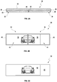
- FIGS. 2A-2D are schematic illustrations of example embodiments of the display system described herein from different perspectives.
- the known display arrangement 2 is illustrated in FIG. 1A in a sectional view and in FIGS. 1B and 1C respectively from above.
- This display arrangement 2 includes a first display device 4 and a second display device 6 , which are arranged here directly next to one another.
- a cover plate 8 is arranged on these two display fields 4 , 6 .
- Each of these two display fields 4 , 6 includes an active display field 10 , 12 , wherein such an active display field 10 , 12 is respectively surrounded by a frame 14 , 16 .
- a second display content 20 of the second display field 12 of the second display device 6 shows a second part of the vehicle.
- the two display contents 18 , 20 are separated from one another upon observation of the display arrangement 2 by the frames 14 , 16 , which enclose the display fields 10 , 12 of the display devices 4 , 6 , even upon observation through the cover plate 8 .
- the embodiment of the display system 30 described herein which is illustrated schematically in FIGS. 2A-2D , includes a first display device 32 and a second display device 34 , two light-guide structure modules 36 , 38 and a cover plate 40 .
- This display system 30 is illustrated schematically in FIG. 2A in a sectional view.
- FIG. 2B shows the two display devices 32 , 34 of the display system 30 in a schematic illustration from above.
- FIG. 2C shows an appearance image, which is represented for a viewer upon performance of an embodiment of the method described herein by way of the display system 30 , in a schematic illustration.
- FIG. 2D furthermore shows a detail from FIG. 2A in schematic illustration in a region in which the display devices 32 , 34 and the light-guide structure modules 36 , 38 abut.
- Each display device 32 , 34 includes a here active display field 42 , 44 , which is enclosed by a frame 46 , 48 , wherein a respective frame 46 , 48 likewise encloses a respective display device 32 , 34 and/or is embodied as a component of the respective display device 32 , 34 .
- a frame 46 of the first display device 32 has an inner periphery 50 and an outer periphery 52 .
- the inner periphery 50 here encloses and/or delimits the display field 42 of the first display device 32 .
- the outer periphery 52 of the frame 46 which is arranged parallel to the first periphery 50 , delimits and/or encloses here the frame 46 , here in a refinement of an outer edge of the frame 46 of the first display device 32 .
- the frame 48 of the second display device 34 likewise has an inner periphery 54 and an outer periphery 56 , wherein the inner periphery 54 encloses and/or delimits the display field 44 of the second display device 34 .
- the outer periphery 56 here encloses furthermore the frame 48 of the second display device 34 and the outer edge thereof.
- the frames 46 , 48 of both display devices 32 , 34 are thus delimited in each case by an inner periphery 50 , 54 and an outer periphery 52 , 56 , wherein the inner peripheries 50 , 54 are arranged in a straight manner relative to the corresponding outer peripheries 52 , 56 of in each case one frame 46 , 48 and in each case mutually parallel.
- Each of the two light-guide structure modules 36 , 38 has, in the embodiment of the display system 30 , a body in the shape of a truncated pyramid, wherein each light-guide structure module 36 , 38 is embodied to be trapezoidal in cross section ( FIG. 2A ). As shown in detail in FIG. 2D , each light-guide structure module 36 , 38 has a first outer side 58 , 60 and a second outer side 62 , 64 .
- the cover plate 40 is arranged on the two outer sides 62 , 64 of the two light-guide structure modules 36 , 38 , wherein edges of the second outer sides 62 , 64 are in contact along a common line 66 , wherein this common line 66 is at the same time assigned to an inner surface 68 of the cover plate 40 and/or is defined for the cover plate 40 , wherein the two second outer sides 62 , 64 of the two light-guide structure modules 36 , 38 are in contact with this inner surface 68 of the cover plate 40 .
- this cover plate 40 has an outer surface 70 , for which a line 72 is defined here, wherein this line 72 and the line 66 between the edges of the two second outer sides 62 , 64 of the two light-guide structure modules 36 , 38 or on the inner surface 68 are parallel with respect to one another and are connected by an axis 80 , which is oriented perpendicularly to the cover plate 40 , wherein the outer surface 70 and the line 66 on the inner surface 68 of the cover plate 40 face away from the light-guide structure modules 36 , 38 . Provision is additionally made for this line 72 to be arranged on the outer surface 70 of the cover plate 40 .
- a common rectilinear section 74 of the two outer peripheries 52 , 56 of the frames 46 , 48 , which enclose the display fields 42 , 44 of the display devices 32 , 34 , is provided here, which section defines the line 72 by way of parallel projection along the axis 80 . Provision is made here for this common section 74 to be arranged centrally between the two parallel outer peripheries 52 , 56 of the frames 46 , 48 and/or to extend on these two outer peripheries 52 , 56 . In this case, the two outer peripheries 52 , 56 abut at the common section 74 , wherein the common section 74 is assigned to the two outer peripheries 52 , 56 and/or is defined herefor.
- the two frames 46 , 48 are also in seamless contact along their outer peripheries 52 , 56 along the common section 74 .
- a first partial image of a vehicle is represented, as first display content 76 , on the first display field 42 of the first display device 32 .
- second display content 78 a second partial image of the vehicle.
- the two inner peripheries 50 , 54 of the two frames 46 , 48 which enclose the two display fields 42 , 44 , are projected onto the common line 66 of the inner surface 68 of the cover plate 40 and furthermore also onto the line 72 of the outer surface 68 of the cover plate 40 .
- each display content 76 , 78 of a display field 42 , 44 is enlarged by in each case one light-guide structure module 36 , 38 .
- the two display contents 76 , 78 are here composed and/or fused into one common display content 82 , wherein the two individual display contents 76 , 78 are seamlessly connected to one another with masking-out of the frames 46 , 48 ( FIG. 2C ).
- This common display content 82 now completely shows the vehicle, which is representable by the two display fields 42 , 44 in each case only separately and/or partially.
Landscapes
- Engineering & Computer Science (AREA)
- Mechanical Engineering (AREA)
- Physics & Mathematics (AREA)
- Chemical & Material Sciences (AREA)
- Combustion & Propulsion (AREA)
- Transportation (AREA)
- General Physics & Mathematics (AREA)
- Optics & Photonics (AREA)
- Devices For Indicating Variable Information By Combining Individual Elements (AREA)
- Illuminated Signs And Luminous Advertising (AREA)
- Instrument Panels (AREA)
- Details Of Measuring Devices (AREA)
Applications Claiming Priority (4)
| Application Number | Priority Date | Filing Date | Title |
|---|---|---|---|
| DE102017207041.2A DE102017207041B4 (de) | 2017-04-26 | 2017-04-26 | Anzeigesystem |
| DE102017207041.2 | 2017-04-26 | ||
| DE102017207041 | 2017-04-26 | ||
| PCT/EP2018/060057 WO2018197334A1 (de) | 2017-04-26 | 2018-04-19 | Anzeigesystem |
Publications (2)
| Publication Number | Publication Date |
|---|---|
| US20200049887A1 US20200049887A1 (en) | 2020-02-13 |
| US10620373B2 true US10620373B2 (en) | 2020-04-14 |
Family
ID=62089738
Family Applications (1)
| Application Number | Title | Priority Date | Filing Date |
|---|---|---|---|
| US16/342,690 Active US10620373B2 (en) | 2017-04-26 | 2018-04-19 | Display system |
Country Status (5)
| Country | Link |
|---|---|
| US (1) | US10620373B2 (de) |
| EP (1) | EP3615367B1 (de) |
| CN (1) | CN109890647A (de) |
| DE (1) | DE102017207041B4 (de) |
| WO (1) | WO2018197334A1 (de) |
Families Citing this family (2)
| Publication number | Priority date | Publication date | Assignee | Title |
|---|---|---|---|---|
| DE102017207041B4 (de) | 2017-04-26 | 2019-03-28 | Audi Ag | Anzeigesystem |
| CN114655128A (zh) * | 2022-03-03 | 2022-06-24 | 深圳市美灿欣电子科技有限公司 | 可拆tft面板和左右可调式数字车载导航 |
Citations (12)
| Publication number | Priority date | Publication date | Assignee | Title |
|---|---|---|---|---|
| US5675687A (en) | 1995-11-20 | 1997-10-07 | Texas Instruments Incorporated | Seamless multi-section visual display system |
| US6021241A (en) | 1998-07-17 | 2000-02-01 | North Carolina State University | Systems and methods for using diffraction patterns to determine radiation intensity values for areas between and along adjacent sensors of compound sensor arrays |
| US6438296B1 (en) * | 2000-05-22 | 2002-08-20 | Lockhead Martin Corporation | Fiber optic taper coupled position sensing module |
| WO2006009390A1 (en) | 2004-07-20 | 2006-01-26 | Si-Han Kim | Portable display device |
| US20070061068A1 (en) | 2005-09-09 | 2007-03-15 | Mazda Motor Corporation | Information indication device for vehicle |
| DE102008037977A1 (de) | 2008-08-08 | 2010-02-11 | Volkswagen Ag | Anzeigevorrichtung für ein Fahrzeug und Verfahren zum Anzeigen von Information im Innenraum eines Fahrzeugs |
| DE102011075884A1 (de) | 2011-05-16 | 2012-11-22 | Robert Bosch Gmbh | HUD mit holographischen optischen Elementen |
| US8841998B2 (en) * | 2010-05-28 | 2014-09-23 | Yazaki Corporation | On-vehicle display device |
| US20150328989A1 (en) | 2014-05-13 | 2015-11-19 | Japan Display Inc. | On-vehicle meter and display apparatus |
| US9731602B2 (en) * | 2015-01-02 | 2017-08-15 | Hyundai Motor Company | Display apparatus for vehicle and vehicle having the display apparatus |
| DE102017207041A1 (de) | 2017-04-26 | 2018-10-31 | Audi Ag | Anzeigesystem |
| US10509613B2 (en) * | 2016-05-09 | 2019-12-17 | Lg Electronics Inc. | Control device for vehicle |
Family Cites Families (3)
| Publication number | Priority date | Publication date | Assignee | Title |
|---|---|---|---|---|
| CN100374889C (zh) * | 2004-11-16 | 2008-03-12 | 联想(北京)有限公司 | 一种消除拼接显示屏间拼缝的方法及装置 |
| CN102087814B (zh) * | 2010-11-30 | 2016-04-27 | 曹嘉灿 | 一种无边框显示装置及大屏幕显示器 |
| CN102610168A (zh) * | 2011-01-20 | 2012-07-25 | 瀚宇彩晶股份有限公司 | 平面显示器 |
-
2017
- 2017-04-26 DE DE102017207041.2A patent/DE102017207041B4/de active Active
-
2018
- 2018-04-19 US US16/342,690 patent/US10620373B2/en active Active
- 2018-04-19 WO PCT/EP2018/060057 patent/WO2018197334A1/de not_active Ceased
- 2018-04-19 CN CN201880004068.3A patent/CN109890647A/zh active Pending
- 2018-04-19 EP EP18721006.7A patent/EP3615367B1/de active Active
Patent Citations (12)
| Publication number | Priority date | Publication date | Assignee | Title |
|---|---|---|---|---|
| US5675687A (en) | 1995-11-20 | 1997-10-07 | Texas Instruments Incorporated | Seamless multi-section visual display system |
| US6021241A (en) | 1998-07-17 | 2000-02-01 | North Carolina State University | Systems and methods for using diffraction patterns to determine radiation intensity values for areas between and along adjacent sensors of compound sensor arrays |
| US6438296B1 (en) * | 2000-05-22 | 2002-08-20 | Lockhead Martin Corporation | Fiber optic taper coupled position sensing module |
| WO2006009390A1 (en) | 2004-07-20 | 2006-01-26 | Si-Han Kim | Portable display device |
| US20070061068A1 (en) | 2005-09-09 | 2007-03-15 | Mazda Motor Corporation | Information indication device for vehicle |
| DE102008037977A1 (de) | 2008-08-08 | 2010-02-11 | Volkswagen Ag | Anzeigevorrichtung für ein Fahrzeug und Verfahren zum Anzeigen von Information im Innenraum eines Fahrzeugs |
| US8841998B2 (en) * | 2010-05-28 | 2014-09-23 | Yazaki Corporation | On-vehicle display device |
| DE102011075884A1 (de) | 2011-05-16 | 2012-11-22 | Robert Bosch Gmbh | HUD mit holographischen optischen Elementen |
| US20150328989A1 (en) | 2014-05-13 | 2015-11-19 | Japan Display Inc. | On-vehicle meter and display apparatus |
| US9731602B2 (en) * | 2015-01-02 | 2017-08-15 | Hyundai Motor Company | Display apparatus for vehicle and vehicle having the display apparatus |
| US10509613B2 (en) * | 2016-05-09 | 2019-12-17 | Lg Electronics Inc. | Control device for vehicle |
| DE102017207041A1 (de) | 2017-04-26 | 2018-10-31 | Audi Ag | Anzeigesystem |
Non-Patent Citations (6)
| Title |
|---|
| English translation of the International Preliminary Report on Patentability dated Nov. 7, 2019 from International Patent Application No. PCT/EP2018/060057,10 pages. |
| German Office Action dated Apr. 11, 2018 from German Patent Application No. 10 2017 207 041.2, 6 pages. |
| German Office Action dated Dec. 17, 2018 from German Patent Application No. 10 2017 207 041.2, 14 pages. |
| German Office Action dated Nov. 7, 2018 from German Patent Application No. 10 2017 207 041.2, 4 pages. |
| International Search Report dated Jul. 9, 2018 from International Patent No. PCT/EP2018/060057, 2 pages. |
| Wikipedia, "Holografie"; URL: https://de.wikipedia.org/w/index.php?title=Holografie&oldid=162729986; 12 pages. |
Also Published As
| Publication number | Publication date |
|---|---|
| DE102017207041B4 (de) | 2019-03-28 |
| EP3615367B1 (de) | 2020-12-16 |
| US20200049887A1 (en) | 2020-02-13 |
| DE102017207041A1 (de) | 2018-10-31 |
| EP3615367A1 (de) | 2020-03-04 |
| CN109890647A (zh) | 2019-06-14 |
| WO2018197334A1 (de) | 2018-11-01 |
Similar Documents
| Publication | Publication Date | Title |
|---|---|---|
| US8472114B2 (en) | Display device | |
| US9237299B2 (en) | Display apparatus | |
| CN104950504B (zh) | 显示装置及电子设备 | |
| JP5269983B2 (ja) | 表示装置 | |
| EP2851741B1 (de) | Prismenfolienelement und Mehrsichtanzeigefolie damit | |
| CN102308328A (zh) | 显示装置 | |
| CN110178171B (zh) | 多显示器 | |
| KR20090058984A (ko) | 타일드 액정표시장치 | |
| US10620373B2 (en) | Display system | |
| CN110999559B (zh) | 具有间隙层空气过滤器的多层显示器 | |
| US20190113805A1 (en) | Backlight module, display panel, display device | |
| KR20150006331A (ko) | 프리즘 시트 부재 및 이를 포함하는 멀티비젼 디스플레이 장치 | |
| CN105405360B (zh) | 无缝拼接的显示装置 | |
| CN104464558B (zh) | 多屏显示装置 | |
| CN109445167A (zh) | 显示装置 | |
| JP5653538B1 (ja) | 映像表示装置 | |
| US9465249B2 (en) | Display device capable of displaying a continuous image | |
| US20170343857A1 (en) | Optical film and display device with narrow frame | |
| JP5134647B2 (ja) | 表示装置 | |
| JPH1039780A (ja) | 画像表示装置 | |
| US10310175B2 (en) | Display device | |
| KR100929960B1 (ko) | 영상 구현 장치 및 이에 있어서 스크린 구조물 | |
| WO2015015925A1 (ja) | 表示装置 | |
| CN104464534B (zh) | 显示模块及具有该显示模块的显示装置 | |
| Miñano et al. | Time multiplexing for increased FOV and resolution in virtual reality |
Legal Events
| Date | Code | Title | Description |
|---|---|---|---|
| AS | Assignment |
Owner name: AUDI AG, GERMANY Free format text: ASSIGNMENT OF ASSIGNORS INTEREST;ASSIGNOR:WALL, CHRISTIAN;REEL/FRAME:048913/0451 Effective date: 20190415 |
|
| FEPP | Fee payment procedure |
Free format text: ENTITY STATUS SET TO UNDISCOUNTED (ORIGINAL EVENT CODE: BIG.); ENTITY STATUS OF PATENT OWNER: LARGE ENTITY |
|
| STCF | Information on status: patent grant |
Free format text: PATENTED CASE |
|
| MAFP | Maintenance fee payment |
Free format text: PAYMENT OF MAINTENANCE FEE, 4TH YEAR, LARGE ENTITY (ORIGINAL EVENT CODE: M1551); ENTITY STATUS OF PATENT OWNER: LARGE ENTITY Year of fee payment: 4 |