US1063473A - Universal plumb. - Google Patents
Universal plumb. Download PDFInfo
- Publication number
- US1063473A US1063473A US72804012A US1912728040A US1063473A US 1063473 A US1063473 A US 1063473A US 72804012 A US72804012 A US 72804012A US 1912728040 A US1912728040 A US 1912728040A US 1063473 A US1063473 A US 1063473A
- Authority
- US
- United States
- Prior art keywords
- plumb
- upright
- arms
- instrument
- bearing
- Prior art date
- Legal status (The legal status is an assumption and is not a legal conclusion. Google has not performed a legal analysis and makes no representation as to the accuracy of the status listed.)
- Expired - Lifetime
Links
- 239000011449 brick Substances 0.000 description 4
- 238000010276 construction Methods 0.000 description 4
- 239000000463 material Substances 0.000 description 2
- 229910052729 chemical element Inorganic materials 0.000 description 1
- 230000002452 interceptive effect Effects 0.000 description 1
- 230000004048 modification Effects 0.000 description 1
- 238000012986 modification Methods 0.000 description 1
- 230000000284 resting effect Effects 0.000 description 1
Images

Classifications
-
- E—FIXED CONSTRUCTIONS
- E04—BUILDING
- E04G—SCAFFOLDING; FORMS; SHUTTERING; BUILDING IMPLEMENTS OR AIDS, OR THEIR USE; HANDLING BUILDING MATERIALS ON THE SITE; REPAIRING, BREAKING-UP OR OTHER WORK ON EXISTING BUILDINGS
- E04G21/00—Preparing, conveying, or working-up building materials or building elements in situ; Other devices or measures for constructional work
- E04G21/14—Conveying or assembling building elements
- E04G21/16—Tools or apparatus
- E04G21/18—Adjusting tools; Templates
- E04G21/1808—Holders for bricklayers' lines, bricklayers' bars; Sloping braces
Definitions
- This invention relates to universal plumbs especially designed for brick layers, masons, carpenters and other artisans.
- the objects of my invention are to pr0- vide: First, an instrument of precision embo-dying positive and reliable means, as hereinafter set forth, for facilitating the construction of walls, columns and other structures. Second, a plumb that can be located upon one of the corners of a column whereby the other corners of a column can be accurately ascertained. Third, a plumb embodying means whereby lines can be ac curately stretched and supported for the laying of a wall or any projections thereof. Fourth, an instrument that serves as a spacing device to obtain accuracy in spacing courses of bricks or other material to be laid. Fifth, an instrument that obviates the necessity of constructing several courses at the corners of walls in order to obtain guide lines for the construction of the remainder of the walls, the instrument permitting of,
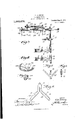
- FIG. 1 is a plan of a portion of the instrument
- Fig. 2 is a front elevation of the same
- Fig. 3 is a side elevation of the instrument
- Fig. 4. is a perspective view of a detached se ment
- Fig. 5 is a perspective view of a detached bearing
- Fig. 6 is a plan of a detached line holder
- Fig. 7 is a cross sectional view of the same
- Fig. 8 is a plan of a detached clamp.
- clamping members 4 upright by transverse pins 2 are the split sleeves 3 of clamping members 4, these mem bers being located one above the other.
- the members are clamped upon the corner of column or wall by adjustable screws 5 having the heads 6 thereof provided with shiftable handles 7.
- the clamping members 4 have angularly disposed arms 8 reinforced by ribs 9 and provided with yieldable con:
- the arms 8 are at right angles f to one another and can be easily clamped upon the corner of a column or walls with out any danger of the side arms injuring the bricks or material to which they are connected.
- T 11 denotes a T slidably mounted upon the upright 1, above the clamping members, and adjustably held thereon by a set screw 12.
- Adjustably mounted in the T 11 by a set screw 13 is the stem 14 of a V-shaped line holder 15, said line holder having right angularly disposed notched arms to which one or more lines (not shown) can be easily and quickly attached.
- the line holder presents a V-shaped notch 16 that cooperates with a plumb bob, to be hereinafter referred to.
- T 17 denotes a T mounted in the upper end of the upright and provided with a set screw 18 for adjustably holding a cylindrical or tubular beam 19 positioned at right angles to said upright.
- the bearing 20 denotes a bearing slidably mounted upon the beam and adjustably held thereon by a set screw 21.
- the bearing is provided with a depending hook 22 and suspended from said hook is a plumb bob 23.
- the bearing 20 has a stud 24 and swiveled upon said stud by a screw bolt 25 are the apertured inner ends of tubular angularly disposed arms 26. Adjustably mounted upon. said arms by set screws 27 are sleeves 28 for depending hooks 29 provided with plumb bobs 30.
- 31 denotes a segment secured to the bearing 20 by ascrew 32 or other fastening means, said segment being also secured to asupporting block resting on the beam 19 by a screw 33 or other fastening means.
- the segment has segment slots 34 and levels 35 and 36 to determine when the segment and the beam 19 are level relatively to a piece of work.
- the instrument as above set forth can be easily clamped on the corners of'walls and in case of any obstruction inside the wall interfering with the beam 19, said beam can be Withdrawn so that it does not extend inside the wall.
- the arms 26 and the segment are removed and simply the plumb, bob 42 employed to locate the line holder.
- the plumb bob 42 cooperates with I the plumb'bobs 30 and 23 in locating the fourcor'ners of a column, the instrument being fastened to one corner of the column, the plumb bob 23 locating the corner to which'the instrument is attached, the plumb bob 4L2 locating the corner opposite that located by the plumb bob 23, and the plumb bobs 3O locating the other corners of the column.
- the instrument has a two-fold purpose.
- F irst that of serving as a support for one or more lines used as a guide for laying a Wall or projections thereof.
- the adjustable arms 26 are'only used when constructing columns whereby the location of four corners at once is desired, or on walls whereby the corner is greater or less than 90 degrees. In cases of long walls other means than the clamping members can be resorted to for supporting the instrument and provision can.
- An instrument of the type described comprising an upright, clamping members adapted to support said upright, a V-shaped notched line holder adjustably mounted upon said upright, a beam adjustably sup ported by the upper end of said upright at right angles thereto, a bearing adjustably mounted upon said beam, a sleeve adjustably mounted upon said beam, plumb bobs supported by said sleeve and said bearing, arms supported by said bearing, and plumb bobs adjustably supported by said arms.
- An instrument of the type described comprising an upright, an adjustable line holder supported by said upright, an adjustable beam positioned upon the upper end of said upright at right angles thereto, a bearing adjustably mounted upon said beam, a segment mounted upon said bearing, arms pivotally mounted above said segment and guided thereby, and adjustable plumb bobs suspended from said beam and said arms.
- An instrument of the type described comprising an upright, an adjustable line holder supported by said upright, an adjustable beam positioned upon the upper end of said upright at right angles thereto, a bearing adjustably mounted upon said beam, a segment mounted upon said bearing, arms pivotally mounted above said segment and guided thereby, adjustable plumb bobs suspended from said beam and said arms, and means connected to said upright and adapted to support said uprightrelatively to a piece of work.
- An instrument of the type described comprising an upright, a line holder adjustably connected thereto, a beam adjustably connected at the upper end of said upright, a bearing adjustably mounted upon said beam, a plumb bob suspended therefrom and adapted to cooperate with said line holder, a segment carried by said bearing, arms pivotally supported above said segment and guided thereby, and plumb bobs adjustably suspended from said arms and said beam.
- An instrument of the type described comprising an upright, a line holder adjustably connected. thereto, a beam adjustably connected at the upper end of said upright, a bearing adjustably mounted upon said beam, a plumb bob suspended therefrom and adapted to coiiperate with said line holder, a segment carried by said bearing, arms pivotally supported above said segment and guided thereby, plumb bobs adjustably suspended from said arms and said beam, and clamping members adapted to hold said upright relatively to a piece of work.
Landscapes
- Engineering & Computer Science (AREA)
- Architecture (AREA)
- Mechanical Engineering (AREA)
- Civil Engineering (AREA)
- Structural Engineering (AREA)
- Conveying And Assembling Of Building Elements In Situ (AREA)
Description
' G. A. SKOOG.
UNIVERSAL PLUMB. APPLICATION FILED 00 1228, 1912.
2 SHEETS-SHEET l.
1,063,473, Patented June 3, 1913.
m w W? WITNE E 1 v 6 INVENTOR s I IMWIHUIHI a. A.5/1 00jf G. A. *SKOOG. UNIVERSAL PLUMB.
ABPLIOATION FILED 00T.28, 1912.
Patented June 3, 1913.
2 SHEETS-SHEET 2.
INVENTOR 6J1 .5K0cy' Ilflllllllllllllll lllll lllIII-II lllllllllllllll Illll ATTORNEYS IA PLANOOIAIH Cm, WM"
GUSTAF ADOLF SKOOG, OF YOUNGSTOWN,- OHIO;
UNIVERSAL PLUMIB.
Specification of-Iietters Patent.
Patented June 3, 1913.
Application filed October 28, 1912. Serial No. 728,040.
To all whom it may concern:
Be it known that I, GUsTAr ADoLr SKooe, a citizen of the United States of America, residing at Youngstown, in the county of Mahoning and State of Ohio, haveinvented certain new and useful Improvements in Universal Plumbs, of which the following is a specification, reference being had therein to the accompanying drawing.
This invention relates to universal plumbs especially designed for brick layers, masons, carpenters and other artisans.
The objects of my invention are to pr0- vide: First, an instrument of precision embo-dying positive and reliable means, as hereinafter set forth, for facilitating the construction of walls, columns and other structures. Second, a plumb that can be located upon one of the corners of a column whereby the other corners of a column can be accurately ascertained. Third, a plumb embodying means whereby lines can be ac curately stretched and supported for the laying of a wall or any projections thereof. Fourth, an instrument that serves as a spacing device to obtain accuracy in spacing courses of bricks or other material to be laid. Fifth, an instrument that obviates the necessity of constructing several courses at the corners of walls in order to obtain guide lines for the construction of the remainder of the walls, the instrument permitting of,
corners and side walls being simultaneously constructed. Sixth, an instrument of the above type that is simple in construction, easy to adjust and inst-all and highly efficient for facilitating the work of artisans.
My invention further aims to accomplish the above results by a mechanical construction that will be hereinafter specifically described and then claimed, and reference will now be had to the drawings, wherein Figure 1 is a plan of a portion of the instrument, Fig. 2 is a front elevation of the same, Fig. 3 is a side elevation of the instrument, Fig. 4. is a perspective view of a detached se ment, Fig. 5 is a perspective view of a detached bearing, Fig. 6 is a plan of a detached line holder, Fig. 7 is a cross sectional view of the same, and Fig. 8 is a plan of a detached clamp.
Further describing my invention in detail with reference to the drawings, wherein like numerals denote corresponding parts throughout 1 denotes a tubular upright and mounted upon the lower ends of said.
upright by transverse pins 2 are the split sleeves 3 of clamping members 4, these mem bers being located one above the other. The members are clamped upon the corner of column or wall by adjustable screws 5 having the heads 6 thereof provided with shiftable handles 7. The clamping members 4 have angularly disposed arms 8 reinforced by ribs 9 and provided with yieldable con:
11 denotes a T slidably mounted upon the upright 1, above the clamping members, and adjustably held thereon by a set screw 12. Adjustably mounted in the T 11 by a set screw 13 is the stem 14 of a V-shaped line holder 15, said line holder having right angularly disposed notched arms to which one or more lines (not shown) can be easily and quickly attached. The line holder presents a V-shaped notch 16 that cooperates with a plumb bob, to be hereinafter referred to. I
17 denotes a T mounted in the upper end of the upright and provided with a set screw 18 for adjustably holding a cylindrical or tubular beam 19 positioned at right angles to said upright.
20 denotes a bearing slidably mounted upon the beam and adjustably held thereon by a set screw 21. The bearing is provided with a depending hook 22 and suspended from said hook is a plumb bob 23. adapted to vertically aline with the notch 16 to determine the vertical outer edge of the corner of walls or a column to be constructed that has the outer edges thereof determined by lines held by the holder 15. The bearing 20 has a stud 24 and swiveled upon said stud by a screw bolt 25 are the apertured inner ends of tubular angularly disposed arms 26. Adjustably mounted upon. said arms by set screws 27 are sleeves 28 for depending hooks 29 provided with plumb bobs 30.
31 denotes a segment secured to the bearing 20 by ascrew 32 or other fastening means, said segment being also secured to asupporting block resting on the beam 19 by a screw 33 or other fastening means. The segment has segment slots 34 and levels 35 and 36 to determine when the segment and the beam 19 are level relatively to a piece of work.
37 denotes supports for the arms 26, said supports having shanks 38 extending into the slots 34 for guiding a movement of said supports that rest upon the segment 31.
39 denotes a sleeve adjustably mounted upon the beam 19 by a set screw 40, said sleeve having a depending hook 41 provided with a plumb 42.
The instrument as above set forth can be easily clamped on the corners of'walls and in case of any obstruction inside the wall interfering with the beam 19, said beam can be Withdrawn so that it does not extend inside the wall. In this instance the arms 26 and the segment are removed and simply the plumb, bob 42 employed to locate the line holder. The plumb bob 42 cooperates with I the plumb'bobs 30 and 23 in locating the fourcor'ners of a column, the instrument being fastened to one corner of the column, the plumb bob 23 locating the corner to which'the instrument is attached, the plumb bob 4L2 locating the corner opposite that located by the plumb bob 23, and the plumb bobs 3O locating the other corners of the column.
From the foregoing it will be observed that the instrument has a two-fold purpose. F irst, that of serving as a support for one or more lines used as a guide for laying a Wall or projections thereof. Second, as a spacing device to obtain accuracy in spacing courses, which is accomplished by raising the line holder upon the upright a predetermined distance to bring the line or lines to a level required for a course of bricks or stones. The adjustable arms 26 are'only used when constructing columns whereby the location of four corners at once is desired, or on walls whereby the corner is greater or less than 90 degrees. In cases of long walls other means than the clamping members can be resorted to for supporting the instrument and provision can. be
made for intermediate supports for long lines between corners.
While in the drawings there is illustrated a preferred embodiment of my invention, it is to be understood that the structural ele ments are susceptible to such variations and modifications as fall within the scope of the appended claims.
What I claim is 1. An instrument of the type described comprising an upright, clamping members adapted to support said upright, a V-shaped notched line holder adjustably mounted upon said upright, a beam adjustably sup ported by the upper end of said upright at right angles thereto, a bearing adjustably mounted upon said beam, a sleeve adjustably mounted upon said beam, plumb bobs supported by said sleeve and said bearing, arms supported by said bearing, and plumb bobs adjustably supported by said arms.
2. An instrument of the type described comprising an upright, an adjustable line holder supported by said upright, an adjustable beam positioned upon the upper end of said upright at right angles thereto, a bearing adjustably mounted upon said beam, a segment mounted upon said bearing, arms pivotally mounted above said segment and guided thereby, and adjustable plumb bobs suspended from said beam and said arms.
3. An instrument of the type described comprising an upright, an adjustable line holder supported by said upright, an adjustable beam positioned upon the upper end of said upright at right angles thereto, a bearing adjustably mounted upon said beam, a segment mounted upon said bearing, arms pivotally mounted above said segment and guided thereby, adjustable plumb bobs suspended from said beam and said arms, and means connected to said upright and adapted to support said uprightrelatively to a piece of work.
4. An instrument of the type described comprising an upright, a line holder adjustably connected thereto, a beam adjustably connected at the upper end of said upright, a bearing adjustably mounted upon said beam, a plumb bob suspended therefrom and adapted to cooperate with said line holder, a segment carried by said bearing, arms pivotally supported above said segment and guided thereby, and plumb bobs adjustably suspended from said arms and said beam.
5. An instrument of the type described comprising an upright, a line holder adjustably connected. thereto, a beam adjustably connected at the upper end of said upright, a bearing adjustably mounted upon said beam, a plumb bob suspended therefrom and adapted to coiiperate with said line holder, a segment carried by said bearing, arms pivotally supported above said segment and guided thereby, plumb bobs adjustably suspended from said arms and said beam, and clamping members adapted to hold said upright relatively to a piece of work.
In testimony whereof? I afliX my signature in the presence of two witnesses.
GUSTAF ADOLF SKOOG.
W itnesses:
M. R. COLEMAN, MAX H. SRoLovrrz.
Copies of this patent may be obtained for five cents each, by addressing the Commissioner of Patents. Washington, D. G.
Priority Applications (1)
| Application Number | Priority Date | Filing Date | Title |
|---|---|---|---|
| US72804012A US1063473A (en) | 1912-10-28 | 1912-10-28 | Universal plumb. |
Applications Claiming Priority (1)
| Application Number | Priority Date | Filing Date | Title |
|---|---|---|---|
| US72804012A US1063473A (en) | 1912-10-28 | 1912-10-28 | Universal plumb. |
Publications (1)
| Publication Number | Publication Date |
|---|---|
| US1063473A true US1063473A (en) | 1913-06-03 |
Family
ID=3131719
Family Applications (1)
| Application Number | Title | Priority Date | Filing Date |
|---|---|---|---|
| US72804012A Expired - Lifetime US1063473A (en) | 1912-10-28 | 1912-10-28 | Universal plumb. |
Country Status (1)
| Country | Link |
|---|---|
| US (1) | US1063473A (en) |
Cited By (1)
| Publication number | Priority date | Publication date | Assignee | Title |
|---|---|---|---|---|
| US2623289A (en) * | 1949-07-18 | 1952-12-30 | Kampel Everett | Guideline supporting apparatus for bricklaying |
-
1912
- 1912-10-28 US US72804012A patent/US1063473A/en not_active Expired - Lifetime
Cited By (1)
| Publication number | Priority date | Publication date | Assignee | Title |
|---|---|---|---|---|
| US2623289A (en) * | 1949-07-18 | 1952-12-30 | Kampel Everett | Guideline supporting apparatus for bricklaying |
Similar Documents
| Publication | Publication Date | Title |
|---|---|---|
| US6598304B2 (en) | Laser leveling system, apparatus and method for building construction | |
| GB2381583A (en) | Measuring and levelling device and method of using same | |
| US3077035A (en) | Tripod and target assembly | |
| KR20110045814A (en) | A multipurpose instrument | |
| US2245646A (en) | Extension plumb rod | |
| CN204718589U (en) | A laser level | |
| US1063473A (en) | Universal plumb. | |
| US4333244A (en) | Leveling stand | |
| US2949673A (en) | Mason's corner-guide and course-gauge | |
| US3442016A (en) | Surveyor's target staff | |
| CN219776711U (en) | Vertical detection device for building | |
| US3349494A (en) | Device for attachment to the corner of a building to facilitate the construction thereof | |
| CN207936901U (en) | The verticality measuring tool of wall column formwork | |
| CN105547249B (en) | A kind of instrument of the control sub- perpendicularity of batter post and angle | |
| GB708448A (en) | Tripod for measuring instruments | |
| US971752A (en) | Leveling and grading instrument. | |
| US583430A (en) | Island | |
| US1256737A (en) | Level. | |
| US2769240A (en) | Mason's corner gauge | |
| US3153285A (en) | Mason's guide | |
| US1145694A (en) | Mason's corner plumb and gage. | |
| US987424A (en) | Plumb for corners, pilasters, and the like. | |
| US771663A (en) | Trigonometrical meter. | |
| US375795A (en) | Device for obtaining vertical lines | |
| US2715777A (en) | Guide lineholder for masons |