US10690183B2 - Motion guide device - Google Patents
Motion guide device Download PDFInfo
- Publication number
- US10690183B2 US10690183B2 US16/333,360 US201716333360A US10690183B2 US 10690183 B2 US10690183 B2 US 10690183B2 US 201716333360 A US201716333360 A US 201716333360A US 10690183 B2 US10690183 B2 US 10690183B2
- Authority
- US
- United States
- Prior art keywords
- rolling
- motion guide
- guide device
- track
- movable block
- Prior art date
- Legal status (The legal status is an assumption and is not a legal conclusion. Google has not performed a legal analysis and makes no representation as to the accuracy of the status listed.)
- Active
Links
- 238000000926 separation method Methods 0.000 claims abstract description 10
- 238000005096 rolling process Methods 0.000 claims description 161
- 238000003780 insertion Methods 0.000 claims description 35
- 230000037431 insertion Effects 0.000 claims description 35
- 238000009434 installation Methods 0.000 description 20
- 238000010586 diagram Methods 0.000 description 14
- 230000000694 effects Effects 0.000 description 4
- 238000000034 method Methods 0.000 description 4
- 210000001364 upper extremity Anatomy 0.000 description 4
- 238000012986 modification Methods 0.000 description 2
- 230000004048 modification Effects 0.000 description 2
- 239000011347 resin Substances 0.000 description 2
- 229920005989 resin Polymers 0.000 description 2
- 230000015572 biosynthetic process Effects 0.000 description 1
- 238000012423 maintenance Methods 0.000 description 1
Images






Classifications
-
- F—MECHANICAL ENGINEERING; LIGHTING; HEATING; WEAPONS; BLASTING
- F16—ENGINEERING ELEMENTS AND UNITS; GENERAL MEASURES FOR PRODUCING AND MAINTAINING EFFECTIVE FUNCTIONING OF MACHINES OR INSTALLATIONS; THERMAL INSULATION IN GENERAL
- F16C—SHAFTS; FLEXIBLE SHAFTS; ELEMENTS OR CRANKSHAFT MECHANISMS; ROTARY BODIES OTHER THAN GEARING ELEMENTS; BEARINGS
- F16C29/00—Bearings for parts moving only linearly
- F16C29/04—Ball or roller bearings
- F16C29/06—Ball or roller bearings in which the rolling bodies circulate partly without carrying load
- F16C29/0633—Ball or roller bearings in which the rolling bodies circulate partly without carrying load with a bearing body defining a U-shaped carriage, i.e. surrounding a guide rail or track on three sides
- F16C29/0635—Ball or roller bearings in which the rolling bodies circulate partly without carrying load with a bearing body defining a U-shaped carriage, i.e. surrounding a guide rail or track on three sides whereby the return paths are provided as bores in a main body of the U-shaped carriage, e.g. the main body of the U-shaped carriage is a single part with end caps provided at each end
- F16C29/0638—Ball or roller bearings in which the rolling bodies circulate partly without carrying load with a bearing body defining a U-shaped carriage, i.e. surrounding a guide rail or track on three sides whereby the return paths are provided as bores in a main body of the U-shaped carriage, e.g. the main body of the U-shaped carriage is a single part with end caps provided at each end with balls
- F16C29/064—Ball or roller bearings in which the rolling bodies circulate partly without carrying load with a bearing body defining a U-shaped carriage, i.e. surrounding a guide rail or track on three sides whereby the return paths are provided as bores in a main body of the U-shaped carriage, e.g. the main body of the U-shaped carriage is a single part with end caps provided at each end with balls with two rows of balls, one on each side of the rail
-
- F—MECHANICAL ENGINEERING; LIGHTING; HEATING; WEAPONS; BLASTING
- F16—ENGINEERING ELEMENTS AND UNITS; GENERAL MEASURES FOR PRODUCING AND MAINTAINING EFFECTIVE FUNCTIONING OF MACHINES OR INSTALLATIONS; THERMAL INSULATION IN GENERAL
- F16C—SHAFTS; FLEXIBLE SHAFTS; ELEMENTS OR CRANKSHAFT MECHANISMS; ROTARY BODIES OTHER THAN GEARING ELEMENTS; BEARINGS
- F16C29/00—Bearings for parts moving only linearly
- F16C29/04—Ball or roller bearings
- F16C29/06—Ball or roller bearings in which the rolling bodies circulate partly without carrying load
-
- F—MECHANICAL ENGINEERING; LIGHTING; HEATING; WEAPONS; BLASTING
- F16—ENGINEERING ELEMENTS AND UNITS; GENERAL MEASURES FOR PRODUCING AND MAINTAINING EFFECTIVE FUNCTIONING OF MACHINES OR INSTALLATIONS; THERMAL INSULATION IN GENERAL
- F16C—SHAFTS; FLEXIBLE SHAFTS; ELEMENTS OR CRANKSHAFT MECHANISMS; ROTARY BODIES OTHER THAN GEARING ELEMENTS; BEARINGS
- F16C29/00—Bearings for parts moving only linearly
- F16C29/04—Ball or roller bearings
- F16C29/06—Ball or roller bearings in which the rolling bodies circulate partly without carrying load
- F16C29/0602—Details of the bearing body or carriage or parts thereof, e.g. methods for manufacturing or assembly
- F16C29/0604—Details of the bearing body or carriage or parts thereof, e.g. methods for manufacturing or assembly of the load bearing section
- F16C29/0607—Details of the bearing body or carriage or parts thereof, e.g. methods for manufacturing or assembly of the load bearing section of parts or members for retaining the rolling elements, i.e. members to prevent the rolling elements from falling out of the bearing body or carriage
-
- F—MECHANICAL ENGINEERING; LIGHTING; HEATING; WEAPONS; BLASTING
- F16—ENGINEERING ELEMENTS AND UNITS; GENERAL MEASURES FOR PRODUCING AND MAINTAINING EFFECTIVE FUNCTIONING OF MACHINES OR INSTALLATIONS; THERMAL INSULATION IN GENERAL
- F16C—SHAFTS; FLEXIBLE SHAFTS; ELEMENTS OR CRANKSHAFT MECHANISMS; ROTARY BODIES OTHER THAN GEARING ELEMENTS; BEARINGS
- F16C29/00—Bearings for parts moving only linearly
- F16C29/08—Arrangements for covering or protecting the ways
- F16C29/084—Arrangements for covering or protecting the ways fixed to the carriage or bearing body movable along the guide rail or track
- F16C29/086—Seals being essentially U-shaped, e.g. for a U-shaped carriage
-
- F—MECHANICAL ENGINEERING; LIGHTING; HEATING; WEAPONS; BLASTING
- F16—ENGINEERING ELEMENTS AND UNITS; GENERAL MEASURES FOR PRODUCING AND MAINTAINING EFFECTIVE FUNCTIONING OF MACHINES OR INSTALLATIONS; THERMAL INSULATION IN GENERAL
- F16C—SHAFTS; FLEXIBLE SHAFTS; ELEMENTS OR CRANKSHAFT MECHANISMS; ROTARY BODIES OTHER THAN GEARING ELEMENTS; BEARINGS
- F16C29/00—Bearings for parts moving only linearly
- F16C29/10—Arrangements for locking the bearings
Definitions
- the present invention relates to a motion guide device.
- Motion guide devices are provided with a track rail, which serves as a track member, formed with a rolling member rolling surface in the longitudinal direction, and with a movable block, which serves as a moving member.
- the movable block is assembled to the track rail so as to be capable of linear motion.
- a plurality of rolling members for reducing frictional resistance are interposed between the track rail and the movable block so as to be capable of rolling motion.
- a circuitous endless circulation passage in a motion guide device is configured by a loaded rolling member rolling passage between the rolling member rolling surface of the track rail and the loaded rolling member rolling surface of the movable block, a rolling member return passage that extends parallel to the loaded rolling member rolling passage, and a pair of U-shaped turnabout passages that connect the loaded rolling member rolling passage and the rolling member return passage (for example, see Patent Literature 1).
- the present invention has been made in view of the above-described circumstances, and an object hereof is to provide a motion guide device that is both compact and capable of withstanding a strong external load.
- a motion guide device includes: a track member formed with a rolling member rolling surface in a longitudinal direction; a moving member that has a loaded rolling member rolling surface opposing the rolling member rolling surface of the track member, a rolling member return passage that extends parallel to a direction in which the rolling member rolling surface extends, and a turnabout passage that connects the loaded rolling member rolling surface and the rolling member return passage together; and a plurality of rolling members that roll through an endless circulation passage formed by a loaded rolling member rolling passage made of the rolling member rolling surface and the loaded rolling member rolling surface, the rolling member return passage, and the pair of turnabout passages, in which the track member has a recess or a protrusion formed in the longitudinal direction, the moving member has a holding protrusion or a holding recess that corresponds to the recess or the protrusion formed to the track member, and when force is applied in a direction that would cause relative separation of the moving member and the track member, the holding protrusion or the holding recess holds onto the recess or the
- the present invention enables a motion guide device that is both compact and capable of withstanding a strong external load to be provided.
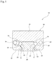
- FIG. 1 is a frontal cross-sectional view of a track rail and a movable block provided to a motion guide device according to an embodiment.
- FIG. 2 is an enlarged view of part of FIG. 1 in accordance with an embodiment of the present invention.
- FIG. 3 is a schematic profile view illustrating an example of an endless circulation passage provided to the motion guide device according to the embodiment.
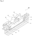
- FIG. 4 is an external perspective view illustrating a motion guide device according to an example.
- FIG. 5 is a frontal view illustrating the motion guide device according to the example.
- FIG. 6 is a side view illustrating the motion guide device according to the example.
- FIG. 7 is an external perspective view illustrating a base member according to the example.
- FIG. 8 is a diagram illustrating a track rail according to the example.
- FIG. 9 is a diagram for explaining a method of securing the track rail to the base member according to the example.
- FIG. 10 is an external perspective view illustrating a state in which the track rail has been secured to the base member according to the example.
- FIG. 11 is a frontal cross-sectional view illustrating the track rail and the movable block provided to the motion guide device according to the example.
- FIG. 12 is an exploded view of the movable block according to the example.
- FIG. 13 is a diagram for explaining a method of securing/releasing the movable block using a brake pin according to the example.
- FIG. 13( a ) is a diagram illustrating a state in which the movable block has been secured
- FIG. 13( b ) illustrates a state in which the movable block has been released.
- FIG. 14 is an external perspective view illustrating a seating apparatus to which motion guide devices according to the example have been applied.
- FIG. 15 is an enlarged view of a motion guide device and a front leg portion of the seating apparatus illustrated in FIG. 14 in accordance with an embodiment of the present invention.
- FIG. 16 is an enlarged view of a motion guide device and a rear leg portion of the seating apparatus illustrated in FIG. 14 in accordance with an embodiment of the present invention.
- FIG. 17 is a diagram illustrating an example of an improved configuration of an adapter plate according to the example.
- FIG. 18 is a diagram illustrating one example of the various possible configurations of a motion guide device in accordance with an embodiment of the present invention.
- FIG. 18 is a schematic perspective view of relevant parts of a motion guide device according to a modified configuration of the present invention.
- FIG. 19 is a diagram illustrating one example of the various possible configurations of a motion guide device in accordance with an embodiment of the present invention.
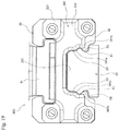
- FIG. 19 is a frontal view of the motion guide device according to the modified configuration of the present invention.
- FIG. 20 is a diagram illustrating one example of the various possible configurations of a motion guide device in accordance with an embodiment of the present invention.
- FIG. 20 is a frontal view of further improved configuration of the motion guide device according to the modified configuration of the present invention.
- FIG. 1 is a frontal cross-sectional view of a track rail and a movable block provided to a motion guide device according to the embodiment.
- FIG. 2 is an enlarged view of part of FIG. 1 .
- FIG. 3 is a schematic profile view illustrating an example of an endless circulation passage provided to the motion guide device according to the embodiment.
- the motion guide device 10 is provided with a track rail 20 , serving as a track member, and with a movable block 30 , serving as a moving member, that is assembled to the track rail 20 with via a plurality of balls 11 , serving as rolling members, so as to be capable of linear motion.
- the track rail 20 is a member that is formed elongated in a longitudinal direction.
- the upper and lower surfaces of the track rail 20 are configured as horizontal surfaces as seen in a vertical cross-section.
- the left and right surfaces of the track rail 20 have projecting and recessed shapes.
- Ball rolling grooves 23 serving as rolling member rolling surfaces, are formed in the surface of the track rail 20 .
- the ball rolling grooves 23 extend in the longitudinal direction of the track rail 20 . In the embodiment, one ball rolling groove 23 is formed in each left and right side of the track rail 20 , with two ball rolling grooves 23 being formed in total.
- each ball rolling groove 23 is formed as circular arc groove made of a single circular arc.
- the radius of curvature of the ball rolling grooves 23 is slightly larger than the radius of the balls 11 , and the balls 11 make point contact with the ball rolling grooves 23 .
- the track rail 20 is formed with recesses 51 in the longitudinal direction.
- the recesses 51 according to the embodiment are formed with substantially trapezoidal shapes in cross-section, and are formed at the lower side of the ball rolling grooves 23 in a state in which the track rail 20 has been disposed on a horizontal surface.
- the movable block 30 is provided with a central portion 31 that opposes the upper surface of the track rail 20 , and with a pair of sidewalls 32 that respectively extend downward from the left and right sides of the central portion 31 and oppose the left and right surfaces of the track rail 20 in a state in which the track rail 20 has been disposed on a horizontal surface.
- the movable block 30 is formed with an overall saddle shape.
- Loaded ball rolling grooves 33 serving as loaded rolling member rolling surfaces, are provided in the movable block 30 .
- the loaded ball rolling grooves 33 oppose the ball rolling grooves 23 in the track rail 20 .
- the cross-sectional shape of each loaded ball rolling groove 33 is formed as a circular arc groove made of a single circular arc, similarly to the ball rolling grooves 23 .
- the radius of curvature of the loaded ball rolling grooves 33 is slightly larger than the radius of the balls 11 , and the balls 11 make point contact with the loaded ball rolling grooves 33 .
- the loaded ball rolling grooves 33 are configured as shapes that fit around and hold the balls 11 . More specifically, when a line in a direction perpendicular to a line connecting the points at which the balls 11 contact the ball rolling grooves 23 and the loaded ball rolling grooves 33 is defined to be a virtual line X, the loaded ball rolling grooves 33 are configured such that portions of the loaded ball rolling grooves 33 past the virtual line X fit around and hold the balls 11 . That is, ends of the loaded ball rolling grooves 33 past the virtual line X are formed becoming narrower such that the balls 11 do not fall. Configuration is thus such that even if the movable block 30 were removed from the track rail 20 , the balls 11 would not fall from the movable block 30 .
- loaded ball rolling passages 24 are formed by the ball rolling grooves 23 in the track rail 20 and the loaded ball rolling grooves 33 , and ball return passages 34 , serving as rolling member return passages, are formed extending parallel to the direction in which the loaded ball rolling passages 24 extend.
- Turnabout passages 35 that connect the loaded ball rolling passages 24 and the ball return passages 34 are also formed.
- Endless circulation passages are formed by the loaded ball rolling passages 24 , the ball return passages 34 , and the pair of turnabout passages 35 .
- the plurality of balls 11 move in a rolling manner while bearing load in the loaded ball rolling passages 24 .
- Balls 11 that have rolled to one end of a loaded ball rolling passage 24 enter the respective ball return passages 34 after having gone through one of the pair of turnabout passages 35 .
- Balls 11 that have passed through the ball return passage 34 re-enter the respective loaded ball rolling passages 24 after having gone through the other of the pair of turnabout passages 35 .
- the movable block 30 is formed with holding protrusions 53 that correspond to the recesses 51 in the track rail 20 .
- the holding protrusions 53 are formed with substantially trapezoidal shapes corresponding to the shapes of the recesses 51 in the track rail 20 , and are formed at the lower side of the loaded ball rolling grooves 33 in a state in which the track rail 20 has been disposed on a horizontal surface. As illustrated in FIG. 2 , a gap ⁇ is formed between the recesses 51 and the holding protrusions 53 .
- the motion guide device 10 when an external load (reverse radial load) of at least a certain value is applied in a direction that would cause relative separation of the movable block 30 and the track rail 20 , the contact points between the balls 11 and the ball rolling grooves 23 and the loaded ball rolling grooves 33 change, and the recesses 51 and the holding protrusions 53 come into contact.
- the holding protrusions 53 and the recesses 51 bear the external load (reverse radial load) due to the recesses 51 and the holding protrusions 53 coming into contact and the holding protrusions 53 holding onto the recesses 51 .
- the track rail 20 and the movable block 30 of the motion guide device 10 according to the embodiment are unable to be separated.
- the gap ⁇ be formed having a width suited to the change in the contact points between the balls 11 and the ball rolling grooves 23 and the loaded ball rolling grooves 33 .
- the gap ⁇ be of a dimension such that reciprocating movement of the movable block 30 relative to the track rail 20 is carried out smoothly when external load (reverse radial load) in a direction that would cause relative separation of the movable block 30 and the track rail 20 is not being applied.
- the gap ⁇ be of a dimension such that the gap ⁇ is maintained within a range where the balls 11 do not fall from the ball rolling grooves 23 , and reciprocating movement of the movable block 30 relative to the track rail 20 is carried out smoothly, even in cases in which a change in the contact points between the balls 11 and the ball rolling grooves 23 and the loaded ball rolling grooves 33 arises due to the application of external load (reverse radial load) in a direction that would cause relative separation of the movable block 30 and the track rail 20 .
- external load reverse radial load
- the gap ⁇ becomes zero and the holding protrusions 53 and the recesses 51 take external load at least immediately prior to the adoption of a state in which there will be a large change in the contact points between the balls 11 and the ball rolling grooves 23 and the loaded ball rolling grooves 33 and the balls 11 are to fall from the ball rolling grooves 23 .
- Setting the gap ⁇ such that these conditions are satisfied makes it possible to realize the motion guide device 10 according to the embodiment, in which the track rail 20 and the movable block 30 are unable to be separated, while still maintaining fundamental motion guide device guiding functionality.
- the ball rolling grooves 23 and the loaded ball rolling grooves 33 are formed as circular arc grooves, configuration is such that the changing of contact points described above is carried out smoothly, and the making and breaking of contact between the recesses 51 and the holding protrusions 53 is carried out smoothly.
- FIG. 4 is an external perspective view illustrating the motion guide device according to the example.
- FIG. 5 is a frontal view illustrating the motion guide device according to the example.
- FIG. 6 is a side view illustrating the motion guide device according to the example.
- FIG. 7 is an external perspective view illustrating a base member according to the example.
- FIG. 8 is a diagram illustrating a track rail according to the example.
- FIG. 9 is a diagram for explaining a method of securing the track rail to the base member according to the example.
- FIG. 4 is an external perspective view illustrating the motion guide device according to the example.
- FIG. 5 is a frontal view illustrating the motion guide device according to the example.
- FIG. 6 is a side view illustrating the motion guide device according to the example.
- FIG. 7 is an external perspective view illustrating a base member according to the example.
- FIG. 8 is a diagram illustrating a track rail according to the example.
- FIG. 9 is a diagram for explaining a method of
- FIG. 10 is an external perspective view illustrating a state in which the track rail has been secured to the base member according to the example.
- FIG. 11 is a frontal cross-sectional view illustrating the track rail and the movable block provided to the motion guide device according to the example.
- FIG. 12 is an exploded view of the movable block according to the example.
- FIG. 13 is a diagram for explaining a method of securing/releasing the movable block using a brake pin according to the example.
- FIG. 13( a ) is a diagram illustrating a state in which the movable block has been secured, and
- FIG. 13( b ) illustrates a state in which the movable block has been released. Note that configuration that is identical or similar to that in the embodiment described above is denoted using identical reference numerals, and explanation thereof is sometimes omitted.
- the motion guide device 100 is provided with a base member 12 , which serves as a base, a track rail 20 serving as a track member, and a movable block 30 that is attached to the track rail 20 via a plurality of balls 11 so as to be capable of linear movement.
- the base member 12 is formed with securing holes 16 for securing the track rail 20 to the base member 12 , and with insertion holes 19 into which a brake pin 43 , described below, can be inserted.
- a plurality of each of the securing holes 16 and the insertion holes 19 are alternatingly formed in the longitudinal direction of the base member 12 .
- the track rail 20 is formed with recesses 51 in the longitudinal direction.
- the recesses 51 according to the example are formed with substantially trapezoidal shapes in cross-section, and are formed at the lower side of the ball rolling grooves 23 in a state in which the track rail 20 has been disposed on the base member 12 .
- the track rail 20 is formed with securing holes 21 for securing the track rail 20 to the base member 12 .
- the securing holes 21 are not only for securing the track rail 20 to the base member 12 , but function as a securing means into which a brake pin 43 , described below, is inserted for placing the movable block 30 into a secured state.
- the cross-sectional shape of each ball rolling groove 23 in the track rail 20 is formed as a circular arc groove made of a single circular arc.
- the sides of the track rail 20 according to the example are formed having cutout portions 22 at locations where the securing holes 21 are formed. Due to having these cutout portions 22 , in the example, configuration is such that in cases in which dirt or the like has entered into the securing holes 21 , this dirt or the like is able to be discharged from the cutout portions 22 . Thus, in the motion guide device 100 according to the example, smooth relative movement of the movable block 30 with respect to the track rail 20 is maintained without being affected by dirt or the like.
- bolts 21 a are inserted in the securing holes 21 formed in the track rail 20 and the securing holes 16 formed in the base member 12 and the bolts are fastened, whereby the track rail 20 is securely installed to the base member 12 as illustrated in FIG. 10 .
- the movable block 30 is provided with a pair of end plates 37 , serving as caps, with cover plates 39 , serving as cap members, provided at both the front and rear ends of the movable block 30 in the direction of movement, with an adapter plate 41 for joining another member and the movable block 30 together, and with a brake pin 43 for securing and releasing the movable block 30 .
- the movable block 30 at a central portion 31 that opposes the upper surface of the track rail 20 in a state in which the track rail 20 has been disposed on the base member 12 , is formed with an adapter plate installation portion 31 a for installing the adapter plate 41 .
- the adapter plate installation portion 31 a is a location that is formed as a substantially inverted-T shaped grooved part as viewed in a vertical cross-section.
- the adapter plate 41 has a substantially inverted-T shape outer shape as viewed in a vertical cross-section corresponding to the shape of the substantially inverted-T shaped adapter plate installation portion 31 a as viewed in a vertical cross-section.
- the adapter plate 41 is inserted into the adapter plate installation portion 31 a while being slid in the longitudinal direction, that is, from the upper right of the page to the lower left of the page in FIG. 12 .
- This makes it possible to install the adapter plate 41 in the adapter plate installation portion 31 a .
- An adapter plate 41 inserted in the adapter plate installation portion 31 a cannot easily be separated from the adapter plate installation portion 31 a due to the effect of the substantially inverted-T shaped grooved part and outer shape.
- the motion guide device 100 has an extremely safe device configuration.
- the movable block 30 is provided with the adapter plate 41 for attaching an external member and with the adapter plate installation portion 31 a for installing the adapter plate 41 , and the adapter plate installation portion 31 a has a grooved part, and the adapter plate 41 has an outer shape similar to that of the grooved part, whereby configuration is such that the adapter plate 41 is able to slidingly inserted into the adapter plate installation portion 31 a .
- configuration may be such that a grooved part is formed in the adapter plate 41 , and the adapter plate installation portion 31 a is formed having an outer shape similar to that of the grooved part.
- the sidewalls 32 of the movable block 30 are formed with securing holes 32 a for securing the end plates 37 to the movable block 30 .
- the central portion 31 of the movable block 30 is formed with securing holes 31 b for securing the cover plates 39 , with securing holes 31 c for securing the adapter plate 41 , and with an insertion hole 31 d for inserting the brake pin 43 .
- the movable block 30 is formed with holding protrusions 53 that correspond to the recesses 51 in the track rail 20 .
- the holding protrusions 53 are formed with substantially trapezoidal shapes corresponding to the shapes of the recesses 51 in the track rail 20 , and are formed at the lower side of the loaded ball rolling grooves 33 in a state in which the track rail 20 has been disposed on the base member 12 .
- a gap ⁇ is formed between the recesses 51 in the track rail 20 and the holding protrusions 53 of the movable block 30 (see FIG. 2 ).
- each loaded ball rolling groove 33 in the movable block 30 is formed as a circular arc groove made of a single circular arc.
- the track rail 20 and the movable block 30 of the motion guide device 100 according to the example are unable to be separated.
- the holding protrusions 53 and the recesses 51 have taken the external load, when the effect of the external load (reverse radial load) is lifted, the contact points between the balls 11 and the ball rolling grooves 23 and the loaded ball rolling grooves 33 revert back to that before the change, contact between the recesses 51 and the holding protrusions 53 is broken such that a gap ⁇ is formed, and the initial state of the motion guide device 100 according to the example is restored.
- the ball rolling grooves 23 and the loaded ball rolling grooves 33 are formed as circular arc grooves, configuration is such that the changing of contact points described above is carried out smoothly, and the making and breaking of contact between the recesses 51 and the holding protrusions 53 is carried out smoothly.
- the end plates 37 are formed having securing holes 37 a for securing the end plates 37 to the movable block 30 .
- the pair of end plates 37 are installed to both the front and rear sides of the movable block 30 in the direction of movement by inserting bolts in the securing holes 37 a and the securing holes 32 a formed in the sidewalls 32 of the movable block 30 for securing the end plates 37 to the movable block 30 and fastening the bolts.
- the insides of the end plates 37 are formed with turnabout passages 35 that configure the endless circulation passage described above. Note that the end plates 37 according to the example are substantially rectangular as viewed face on.
- the cover plates 39 are members formed in substantially an H-shape as viewed face on. Further, as illustrated in FIG. 12 , the cover plates 39 are formed having securing holes 39 a for securing the cover plates 39 to the movable block 30 .
- the cover plates 39 are installed to both the front and rear ends of the movable block 30 in the direction of movement by inserting bolts in the securing holes 39 a and the securing holes 31 b formed in the central portion 31 of the movable block 30 for securing the cover plates 39 to the movable block 30 and fastening the bolts. As illustrated in FIG.
- the cover plates 39 are formed with cover plate holding protrusions 54 , serving as cap member holding protrusions, that correspond to the recesses 51 in the track rail 20 .
- the cover plate holding protrusions 54 are formed at the lower end of the cover plates 39 , with substantially trapezoidal shapes corresponding to the shape of the recesses 51 in the track rail 20 , in a state in which the track rail 20 has been disposed on the base member 12 .
- the cover plates 39 prevent the end plates 37 from striking the track rail 20 when the movable block 30 is installed to the track rail 20 , and also exhibit functionality for guiding the installation of the movable block 30 .
- the adapter plate 41 is provided with securing holes 41 a corresponding to the securing holes 31 c formed in the central portion 31 of the movable block 30 , with an attachment hole 41 b for attaching an external member, and with an insertion hole 42 for inserting the brake pin 43 .
- the adapter plate 41 in a state in which the adapter plate 41 has been slidingly inserted into the adapter plate installation portion 31 a , the adapter plate 41 is securely installed to the adapter plate installation portion 31 a of the movable block 30 by inserting bolts into the securing holes 31 c formed in the central portion 31 of the movable block 30 and the securing holes 41 a formed in the adapter plate 41 and fastening the bolts.
- the brake pin 43 is inserted in the insertion hole 42 in the adapter plate 41 with a bushing 44 made of resin being interposed therebetween.
- the brake pin 43 is inserted in the insertion hole 42 in the adapter plate 41 , the insertion hole 31 d in the movable block 30 , and a securing hole 21 in the track rail 20 so as to secure the movable block 30 to the track rail 20 .
- the brake pin 43 may be inserted as far as an insertion hole 19 formed in the base member 12 . As illustrated in FIG. 13( b ) , when the brake pin 43 is lifted up from the secured state illustrated in FIG.
- the brake pin 43 is removed from a securing hole 21 formed in the track rail 20 , the secured state of movable block 30 with respect to the track rail 20 is released, allowing the movable block 30 to move relative to the track rail 20 .
- the brake pin 43 is inserted in the insertion holes 42 , 31 d with the bushing 44 made of resin being interposed therebetween, the brake pin 43 is able to move up and down smoothly, and an action to secure/release the movable block 30 to/from the track rail 20 is able to be smoothly performed.
- Tapered protrusions 43 a with tapered shapes are formed to the brake pin 43 in the area around the lower side leading end of the brake pin 43 .
- these tapered protrusions 43 a are configured so as to also exhibit functionality as brakes for ensuring that the brake pin 43 does not easily come out from the insertion holes 42 , 31 d . Note that in order to ensure that the brake pin 43 can be smoothly inserted into the insertion hole 42 , it is preferable to adopt configuration in which the area around the entrance of the insertion hole 42 is beveled.
- this securing can be released such that the movable block 30 can be moved relative to the track rail 20 .
- FIG. 14 is an external perspective view illustrating a seating apparatus to which motion guide devices according to the example have been applied.
- FIG. 15 is an enlarged view of a motion guide device and a front leg portion of the seating apparatus illustrated in FIG. 14 .
- FIG. 16 is an enlarged view of a motion guide device and a rear leg portion of the seating apparatus illustrated in FIG. 14 .
- motion guide devices 100 can, for example, be applied to an aircraft seating apparatus 200 .
- the seating apparatus 200 is configured including legs 210 , 215 , and a seat section 220 .
- the legs 210 , 215 are each joined to an adapter plate 41 installed to the movable block 30 of a motion guide device 100 . Note that this joining is made possible using the attachment holes 41 b formed in the adapter plates 41 .
- each movable block 30 configuring a motion guide device 100 is provided with relief portions 31 e formed by making cutouts in the upper sides of both sidewalls of the central portion 31 such that open space is formed around the attachment holes 41 b , whereby it becomes possible to tilt the external members (legs 210 , 215 ).
- the relief portions 31 e are each formed by a centrally-positioned straight portion and two curved portions positioned on either side of the straight portion.
- the relief portions 31 e are shaped such that, for example, even in cases in which the legs 210 , 215 of the aircraft seating apparatus 200 are of a type able to be folded, the relief portions 31 e do not obstruct the tilting action of the legs 210 , 215 .
- the relief portions 31 e according to the example are each formed by a centrally-positioned straight portion and two curved portions positioned on either side of the straight portion, and adopt the shape of a substantially ellipsoid form divided in half.
- any shape may be adopted as the shape of the relief portions according to the present invention provided that the tilting action of external members such as the legs 210 , 215 is not obstructed. For example, at the location illustrated in FIG.
- the outer dimension of the cutouts (L 1 ) for the relief portions cut out at the upper sides of both sidewalls of the central portion 31 be configured such that (L 1 )>(L).
- the brake pin 43 is inserted into the insertion hole 42 formed in the adapter plate 41 and the insertion hole 31 d formed in the movable block 30 .
- a brake pin 43 is not inserted into the insertion hole 42 formed in the adapter plate 41 or the insertion hole 31 d formed in the movable block 30 .
- a brake pin 43 may be inserted in the insertion holes 42 , 31 d in a movable block 30 to which a rear leg 215 is joined. Further, configuration may be adopted in which a brake pin 43 is inserted into the insertion holes 42 , 31 d in a movable block 30 to which a rear leg 215 is joined, and a brake pin 43 is not inserted into the insertion holes 42 , 31 d in a movable block 30 to which a front leg 210 is joined.
- a rear leg 215 is secured to a track rail 20 by inserting a brake pin 43 into the insertion hole 42 in the adapter plate 41 to which the rear leg 215 is joined, the insertion hole 31 d formed in the respective movable blocks 30 , and a securing hole 21 formed in the track rail 20 .
- the whole seating apparatus 200 is secured to the track rails 20 .
- the legs 210 , 215 and the seat section 220 are able to be moved to and secured at desired positions on the track rails 20 .
- the holding protrusions 53 and the recesses 51 bear the impact load (reverse radial load) in a direction that would cause the movable blocks 30 to separate from the track rails 20 .
- the track rails 20 and the legs 210 , 215 joined to the movable blocks 30 are unable to be separated.
- the holding protrusions 53 and the recesses 51 have taken the impact load, when the contact points between the balls 11 and the ball rolling grooves 23 and the loaded ball rolling grooves 33 revert back to that before the change, contact between the recesses 51 and the holding protrusions 53 is broken such that gaps ⁇ are formed, and the initial state of the motion guide devices 100 and the seating apparatus 200 is restored.
- the seating apparatus 200 this being one example application of motion guide devices 100 according to the example, has been described in the foregoing.
- the recesses 51 formed in the track rail 20 and the holding protrusions 53 formed to the movable block 30 are able to bear external load in an appropriate manner, and are thus able to be suitably applied to apparatuses to which there is a chance that a strong external load will be applied.
- motion guide devices are made larger so as to be able to withstand a strong external load.
- the motion guide devices 10 , 100 described above are able to suitably bear external load so long as the recesses 51 formed in the track rails 20 and the holding protrusions 53 formed to the movable block 30 have been formed, and thus are able to be made compact, without an increase in the size of the motion guide device.
- the recesses 51 are formed in the longitudinal direction of the track rail 20 and the movable block 30 is formed with the holding protrusions 53 that correspond to these recesses 51
- configuration may be such that protrusions are formed in the longitudinal direction of the track rails 20 and the movable block 30 is formed with holding recesses that correspond to these protrusions.
- cover plate holding recesses serving as cap member holding recesses, that correspond to the protrusions formed to the track rails 20 may be formed in the cover plates 39 .
- the adapter plate 41 can be configured with an insertion groove 41 c formed in the bottom face side of the adapter plate 41 such that when the adapter plate 41 is inserted into the adapter plate installation portion 31 a while being slid, an inner wall of the insertion groove 41 c strikes and makes contact with the bushing 44 at a prescribed position.
- the formation of an insertion groove 41 c such as illustrated in FIG.
- FIG. 17 is a diagram illustrating an example of an improved configuration of an adapter plate according to the example.
- the adapter plate 41 is provided separately to the movable block 30 , the adapter plate 41 can be integrally formed to the movable block 30 .
- FIGS. 18 to 20 illustrate an example of such a modified configuration.
- FIGS. 18 to 20 are diagrams illustrating one example of the various possible configurations of a motion guide device according to the present invention.
- FIG. 18 is a schematic perspective view of relevant parts of a motion guide device according to a modified configuration of the present invention, FIG.
- FIG. 19 is a frontal view of the motion guide device according to the modified configuration of the present invention
- FIG. 20 is a frontal view of a further improved configuration of the motion guide device according to the modified configuration of the present invention.
- a pair of cover plate portions 339 serving as cap members, configuring a movable block 30 and a pair of end plate portions 337 , serving as caps, to which a pair of turnabout passages 35 are formed are configured as cover end plates 340 , which are integrated members.
- the cover end plates 340 are further improved over the example described above, and for example as illustrated in FIG. 19 , at locations on the cover end plates 340 opposing the track rails 20 , are formed with a bevel 341 .
- a motion guide device such as in the present invention
- there is demand to be able to remove the movable block 30 is from the track rail 20 to perform a maintenance or adjustment operation, or perform an operation to attach an external member or the like.
- it is necessary to reattach the movable block 30 to the track rail 20 and there is demand to be able to perform this attachment operation smoothly.
- locations on the cover end plates 340 opposing the track rails 20 are formed with the bevel 341 .
- the bevel 341 is provided at both the front and rear ends of the movable block 30 in the direction of movement, when inserting the movable block 30 over the track rail 20 , the insertion action is guided following the outer shape of the track rail 20 , helping a smooth attachment operation to be realized.
- the bevel 341 of the cover end plate 340 is formed as a location having a shape with a guide portion 341 a shaped corresponding to rolling member rolling surfaces 23 formed to the track rail 20 and separated portions 341 b that are formed away from the recesses 51 formed in the track rail 20 .
- the bevel 341 follows the outer shape of the track rail 20 even more, allowing incorrect insertion to be suitably prevented, such as, for example, when the holding protrusions 53 formed to the sidewalls 32 of the movable block 30 are inserted in the rolling member rolling surfaces 23 formed to the track rail 20 .
- opposing surfaces of the recesses 51 and the holding protrusions 53 that form the gap ⁇ are formed by two surfaces disposed in parallel when the motion guide device 20 is viewed in a vertical cross-section.
- the external load exerted on the movable block 30 assembled to the track rail 20 is not only reverse radial load acting the vertical direction, but is also load acting in a direction in which the movable block 30 rotates with respect to the track rail 20 .
- opposing surfaces of the recesses 51 and the holding protrusions 53 are disposed so as to be non-parallel when the motion guide device 300 is viewed in a vertical cross-section.
- the opposing surfaces of the recesses 51 and the holding protrusions 53 that are disposed so as to be non-parallel can, for example as illustrated in FIG. 20 , be formed as surfaces that oppose one another in a state having an angle ⁇ .
- Forming the gap ⁇ using two such surfaces that are disposed so as to be non-parallel allows external load from to be taken from any direction. Setting the gap ⁇ so as to have such a configuration makes it possible to realize the motion guide device 300 according to the modified configuration of the present invention, in which the track rail 20 and the movable block 30 are unable to be separated, while still maintaining fundamental motion guide device guiding functionality.
- the holding protrusions 53 formed to the movable block 30 are able to be formed with a size and shape such that insertion in the rolling member rolling surfaces 23 formed to the track rail 20 is not possible.
- configuration may be such that when the motion guide device 30 is viewed in a vertical cross-section with reference to the track rail 20 , compared to the position of the bottom surface of the rolling member rolling surfaces 23 furthest to the inside of the rail, the position of the leading end of the holding protrusions 53 furthest to the inside of the rail is positioned further inward of the track rail 20 by a distance ⁇ .
- the distance between the leading ends of the left and right pair of holding protrusions 53 formed to the movable block 30 is formed so as to be shorter than the distance between the bottom surfaces of the left and right pair of rolling member rolling surfaces 23 formed to the track rail 20 by the amount “2 ⁇ ”. Adopting this configuration makes it possible to physically and completely prevent incorrect insertion, such as when the holding protrusions 53 formed to the sidewalls 32 of the movable block 30 are inserted in the rolling member rolling surfaces 23 formed to the track rail 20 . Due to having the above configuration, the motion guide device 300 according to the modified configuration of the present invention makes it possible for operations to remove the movable block 30 from the track rail 20 and operations to attach the movable block 30 to the track rail 20 to be smoothly implemented.
Landscapes
- Engineering & Computer Science (AREA)
- General Engineering & Computer Science (AREA)
- Mechanical Engineering (AREA)
- Bearings For Parts Moving Linearly (AREA)
Applications Claiming Priority (5)
| Application Number | Priority Date | Filing Date | Title |
|---|---|---|---|
| JP2016-182195 | 2016-09-16 | ||
| JP2016182195 | 2016-09-16 | ||
| JP2016-255740 | 2016-12-28 | ||
| JP2016255740A JP6857027B2 (ja) | 2016-09-16 | 2016-12-28 | 運動案内装置 |
| PCT/JP2017/029663 WO2018051724A1 (ja) | 2016-09-16 | 2017-08-18 | 運動案内装置 |
Publications (2)
| Publication Number | Publication Date |
|---|---|
| US20190211870A1 US20190211870A1 (en) | 2019-07-11 |
| US10690183B2 true US10690183B2 (en) | 2020-06-23 |
Family
ID=61767374
Family Applications (1)
| Application Number | Title | Priority Date | Filing Date |
|---|---|---|---|
| US16/333,360 Active US10690183B2 (en) | 2016-09-16 | 2017-08-18 | Motion guide device |
Country Status (3)
| Country | Link |
|---|---|
| US (1) | US10690183B2 (de) |
| EP (1) | EP3514399B1 (de) |
| JP (2) | JP2018048732A (de) |
Cited By (1)
| Publication number | Priority date | Publication date | Assignee | Title |
|---|---|---|---|---|
| USD927288S1 (en) * | 2017-05-09 | 2021-08-10 | Thk Co., Ltd. | Ball retainer belt |
Families Citing this family (1)
| Publication number | Priority date | Publication date | Assignee | Title |
|---|---|---|---|---|
| KR102520335B1 (ko) * | 2022-10-04 | 2023-04-11 | 디씨티 주식회사 | 무빙마그넷타입 이송시스템의 연결단에 사용되는 직선볼베어링 가이드 조립체 |
Citations (14)
| Publication number | Priority date | Publication date | Assignee | Title |
|---|---|---|---|---|
| JPS5388438A (en) | 1977-01-14 | 1978-08-03 | Hidemasa Iwamoto | Ball spline |
| JPS62141308A (ja) | 1985-12-13 | 1987-06-24 | Ntn Toyo Bearing Co Ltd | 直線運動用軸受 |
| US5011300A (en) * | 1988-08-16 | 1991-04-30 | Thk Co., Ltd. | Linear sliding bearing |
| DE9320181U1 (de) | 1993-12-30 | 1994-05-05 | Hiwin Tech Corp | Linearkugelführung |
| US5800065A (en) | 1997-05-16 | 1998-09-01 | Thomson Industries, Inc. | Linear motion bearing sub-assembly with inserted races |
| JP2000193023A (ja) | 1998-12-25 | 2000-07-14 | Naganori Sato | 2軸付ガイドユニット |
| DE10051004A1 (de) * | 2000-10-14 | 2002-04-18 | Ina Schaeffler Kg | Linearwälzlager |
| AU2004235657A1 (en) | 1999-07-13 | 2005-01-06 | Harken, Inc. | Traveler car with recirculating ball bearings and bearing retainer |
| JP2005201333A (ja) | 2004-01-14 | 2005-07-28 | Nsk Ltd | 直動装置 |
| JP2006017253A (ja) | 2004-07-02 | 2006-01-19 | Nsk Ltd | 直動案内装置の転動体挿入方法 |
| US20070133910A1 (en) | 2003-12-05 | 2007-06-14 | Nsk Ltd. | Linear guide device |
| US8033730B2 (en) * | 2007-05-25 | 2011-10-11 | Nippon Thompson Co., Ltd. | Linear motion guide unit with rollers |
| DE112012004674T5 (de) | 2011-11-09 | 2014-09-18 | Thk Co., Ltd. | Vorrichtung zur Bewegungsführung |
| JP2015110990A (ja) | 2013-10-29 | 2015-06-18 | Thk株式会社 | 転がり案内装置及びこれを備えた転がり案内ユニット |
Family Cites Families (1)
| Publication number | Priority date | Publication date | Assignee | Title |
|---|---|---|---|---|
| JPH03111143A (ja) * | 1989-09-22 | 1991-05-10 | Yamazaki Mazak Corp | ローラガイド及び支持構造 |
-
2016
- 2016-12-28 JP JP2016255741A patent/JP2018048732A/ja active Pending
- 2016-12-28 JP JP2016255740A patent/JP6857027B2/ja active Active
-
2017
- 2017-08-18 US US16/333,360 patent/US10690183B2/en active Active
- 2017-08-18 EP EP17850630.9A patent/EP3514399B1/de active Active
Patent Citations (15)
| Publication number | Priority date | Publication date | Assignee | Title |
|---|---|---|---|---|
| JPS5388438A (en) | 1977-01-14 | 1978-08-03 | Hidemasa Iwamoto | Ball spline |
| JPS62141308A (ja) | 1985-12-13 | 1987-06-24 | Ntn Toyo Bearing Co Ltd | 直線運動用軸受 |
| US5011300A (en) * | 1988-08-16 | 1991-04-30 | Thk Co., Ltd. | Linear sliding bearing |
| DE9320181U1 (de) | 1993-12-30 | 1994-05-05 | Hiwin Tech Corp | Linearkugelführung |
| US5800065A (en) | 1997-05-16 | 1998-09-01 | Thomson Industries, Inc. | Linear motion bearing sub-assembly with inserted races |
| JP2000193023A (ja) | 1998-12-25 | 2000-07-14 | Naganori Sato | 2軸付ガイドユニット |
| AU2004235657A1 (en) | 1999-07-13 | 2005-01-06 | Harken, Inc. | Traveler car with recirculating ball bearings and bearing retainer |
| DE10051004A1 (de) * | 2000-10-14 | 2002-04-18 | Ina Schaeffler Kg | Linearwälzlager |
| US20070133910A1 (en) | 2003-12-05 | 2007-06-14 | Nsk Ltd. | Linear guide device |
| JP2005201333A (ja) | 2004-01-14 | 2005-07-28 | Nsk Ltd | 直動装置 |
| JP2006017253A (ja) | 2004-07-02 | 2006-01-19 | Nsk Ltd | 直動案内装置の転動体挿入方法 |
| US8033730B2 (en) * | 2007-05-25 | 2011-10-11 | Nippon Thompson Co., Ltd. | Linear motion guide unit with rollers |
| DE112012004674T5 (de) | 2011-11-09 | 2014-09-18 | Thk Co., Ltd. | Vorrichtung zur Bewegungsführung |
| US20140301677A1 (en) | 2011-11-09 | 2014-10-09 | Thk Co., Ltd. | Motion guide device |
| JP2015110990A (ja) | 2013-10-29 | 2015-06-18 | Thk株式会社 | 転がり案内装置及びこれを備えた転がり案内ユニット |
Non-Patent Citations (2)
| Title |
|---|
| Extended (Supplementary) European Search Report dated Jul. 12, 2019, issued in counterpart EP application No. 17850630.9. (8 pages). |
| International Search Report dated Sep. 12, 2017, issued in counterpart application No. PCT/JP2017/029663 (2 pages). |
Cited By (1)
| Publication number | Priority date | Publication date | Assignee | Title |
|---|---|---|---|---|
| USD927288S1 (en) * | 2017-05-09 | 2021-08-10 | Thk Co., Ltd. | Ball retainer belt |
Also Published As
| Publication number | Publication date |
|---|---|
| JP2018048732A (ja) | 2018-03-29 |
| JP6857027B2 (ja) | 2021-04-14 |
| EP3514399A1 (de) | 2019-07-24 |
| EP3514399B1 (de) | 2021-08-04 |
| US20190211870A1 (en) | 2019-07-11 |
| JP2018048731A (ja) | 2018-03-29 |
| EP3514399A4 (de) | 2019-08-14 |
Similar Documents
| Publication | Publication Date | Title |
|---|---|---|
| US10351023B2 (en) | Seat moving/securing device | |
| EP2571800B1 (de) | Führungsschiene aus blech für ein aufzugssystem | |
| US4483504A (en) | Slide rail assemblies | |
| EP2767433B1 (de) | Fahrzeugsitzschiene | |
| US10690183B2 (en) | Motion guide device | |
| JP2013534193A (ja) | 分離可能なアッパ及びロアレールを含む車両シート用長手方向調整デバイス | |
| KR20100040850A (ko) | 컨베이어용 트레드 부재 | |
| WO2012087295A1 (en) | Sheet metal elevator rail connector | |
| CN103085684A (zh) | 一种汽车、汽车座椅及其滑轨机构 | |
| CN110494663A (zh) | 运动引导装置 | |
| JP5448866B2 (ja) | エレベータの非常止め装置 | |
| WO2018116926A1 (ja) | 機器固定装置 | |
| WO2018051724A1 (ja) | 運動案内装置 | |
| CN107466287B (zh) | 电梯安全钳导引组合件和方法 | |
| JP2008280118A (ja) | エレベータのかご室 | |
| JP6054436B2 (ja) | フェッシャープレート | |
| KR101507379B1 (ko) | 강도 안전성을 개선한 시트 트랙 | |
| KR20140004966U (ko) | 호차 체결구조 | |
| KR101794473B1 (ko) | 차량 리프트 상판 | |
| CN203046937U (zh) | 一种汽车、汽车座椅及其滑轨机构 | |
| ES3040068T3 (en) | Blocking device for the car of an elevator system | |
| JP5951813B1 (ja) | フェッシャープレート | |
| KR101732606B1 (ko) | 방폭 구조물 | |
| JP2016175740A (ja) | 乗客コンベア | |
| JP2022042382A (ja) | フェッシャープレート装置 |
Legal Events
| Date | Code | Title | Description |
|---|---|---|---|
| FEPP | Fee payment procedure |
Free format text: ENTITY STATUS SET TO UNDISCOUNTED (ORIGINAL EVENT CODE: BIG.); ENTITY STATUS OF PATENT OWNER: LARGE ENTITY |
|
| AS | Assignment |
Owner name: THK CO., LTD., JAPAN Free format text: ASSIGNMENT OF ASSIGNORS INTEREST;ASSIGNORS:MOCHIZUKI, HIROAKI;HOSAKA, EIJI;KURIBAYASHI, HIROOMI;AND OTHERS;REEL/FRAME:048659/0992 Effective date: 20190315 |
|
| STPP | Information on status: patent application and granting procedure in general |
Free format text: NON FINAL ACTION MAILED |
|
| STPP | Information on status: patent application and granting procedure in general |
Free format text: RESPONSE TO NON-FINAL OFFICE ACTION ENTERED AND FORWARDED TO EXAMINER |
|
| STPP | Information on status: patent application and granting procedure in general |
Free format text: PUBLICATIONS -- ISSUE FEE PAYMENT VERIFIED |
|
| STCF | Information on status: patent grant |
Free format text: PATENTED CASE |
|
| MAFP | Maintenance fee payment |
Free format text: PAYMENT OF MAINTENANCE FEE, 4TH YEAR, LARGE ENTITY (ORIGINAL EVENT CODE: M1551); ENTITY STATUS OF PATENT OWNER: LARGE ENTITY Year of fee payment: 4 |