US10696079B2 - Printer device for thermal printing or embossing - Google Patents
Printer device for thermal printing or embossing Download PDFInfo
- Publication number
- US10696079B2 US10696079B2 US15/554,973 US201615554973A US10696079B2 US 10696079 B2 US10696079 B2 US 10696079B2 US 201615554973 A US201615554973 A US 201615554973A US 10696079 B2 US10696079 B2 US 10696079B2
- Authority
- US
- United States
- Prior art keywords
- swivel
- arrangement
- carrier film
- roller
- printer device
- Prior art date
- Legal status (The legal status is an assumption and is not a legal conclusion. Google has not performed a legal analysis and makes no representation as to the accuracy of the status listed.)
- Active, expires
Links
- 238000004049 embossing Methods 0.000 title claims abstract description 16
- 238000007651 thermal printing Methods 0.000 title claims abstract description 12
- 238000004040 coloring Methods 0.000 claims abstract description 18
- 238000007639 printing Methods 0.000 claims abstract description 17
- 239000000758 substrate Substances 0.000 claims abstract description 11
- 238000005259 measurement Methods 0.000 claims description 8
- 230000001105 regulatory effect Effects 0.000 claims description 3
- 238000000034 method Methods 0.000 description 15
- 238000010438 heat treatment Methods 0.000 description 5
- 238000000859 sublimation Methods 0.000 description 5
- 230000008022 sublimation Effects 0.000 description 5
- 238000010023 transfer printing Methods 0.000 description 5
- 238000013459 approach Methods 0.000 description 3
- 230000003287 optical effect Effects 0.000 description 3
- 230000035945 sensitivity Effects 0.000 description 3
- 238000010586 diagram Methods 0.000 description 2
- 239000002245 particle Substances 0.000 description 2
- 230000003139 buffering effect Effects 0.000 description 1
- 230000001276 controlling effect Effects 0.000 description 1
- 238000013461 design Methods 0.000 description 1
- 238000011161 development Methods 0.000 description 1
- 238000010017 direct printing Methods 0.000 description 1
- 239000000428 dust Substances 0.000 description 1
- 230000002349 favourable effect Effects 0.000 description 1
- 238000012546 transfer Methods 0.000 description 1
Images



Classifications
-
- B—PERFORMING OPERATIONS; TRANSPORTING
- B41—PRINTING; LINING MACHINES; TYPEWRITERS; STAMPS
- B41M—PRINTING, DUPLICATING, MARKING, OR COPYING PROCESSES; COLOUR PRINTING
- B41M5/00—Duplicating or marking methods; Sheet materials for use therein
- B41M5/26—Thermography ; Marking by high energetic means, e.g. laser otherwise than by burning, and characterised by the material used
- B41M5/382—Contact thermal transfer or sublimation processes
-
- B—PERFORMING OPERATIONS; TRANSPORTING
- B41—PRINTING; LINING MACHINES; TYPEWRITERS; STAMPS
- B41J—TYPEWRITERS; SELECTIVE PRINTING MECHANISMS, i.e. MECHANISMS PRINTING OTHERWISE THAN FROM A FORME; CORRECTION OF TYPOGRAPHICAL ERRORS
- B41J2/00—Typewriters or selective printing mechanisms characterised by the printing or marking process for which they are designed
- B41J2/315—Typewriters or selective printing mechanisms characterised by the printing or marking process for which they are designed characterised by selective application of heat to a heat sensitive printing or impression-transfer material
- B41J2/32—Typewriters or selective printing mechanisms characterised by the printing or marking process for which they are designed characterised by selective application of heat to a heat sensitive printing or impression-transfer material using thermal heads
- B41J2/325—Typewriters or selective printing mechanisms characterised by the printing or marking process for which they are designed characterised by selective application of heat to a heat sensitive printing or impression-transfer material using thermal heads by selective transfer of ink from ink carrier, e.g. from ink ribbon or sheet
-
- B—PERFORMING OPERATIONS; TRANSPORTING
- B41—PRINTING; LINING MACHINES; TYPEWRITERS; STAMPS
- B41F—PRINTING MACHINES OR PRESSES
- B41F19/00—Apparatus or machines for carrying out printing operations combined with other operations
- B41F19/02—Apparatus or machines for carrying out printing operations combined with other operations with embossing
-
- B—PERFORMING OPERATIONS; TRANSPORTING
- B41—PRINTING; LINING MACHINES; TYPEWRITERS; STAMPS
- B41J—TYPEWRITERS; SELECTIVE PRINTING MECHANISMS, i.e. MECHANISMS PRINTING OTHERWISE THAN FROM A FORME; CORRECTION OF TYPOGRAPHICAL ERRORS
- B41J35/00—Other apparatus or arrangements associated with, or incorporated in, ink-ribbon mechanisms
- B41J35/04—Ink-ribbon guides
- B41J35/08—Ink-ribbon guides with tensioning arrangements
Definitions
- the invention relates to a printer device for thermal printing or embossing.
- thermal transfer printing and dye sublimation printing Two known printing methods are thermal transfer printing and dye sublimation printing. These two printing methods are based on the basic principle that a carrier film coated with coloring matter is guided onto the medium to be printed and heated by means of a thermal print head.
- This thermal print head has a multiplicity of heating elements which can be individually heated and constitute individual image points—that is to say pixels—for this printing method.
- a heated heating element causes the coloring matter at the appropriate point on the carrier film to detach and to be absorbed by the medium to be printed—referred to as substrate—where, in turn, it solidifies.
- substrate where, in turn, it solidifies.
- ink particles are released sectionally from the ink ribbon and transferred to the object to be printed.
- the detachment of the coloring matter is effected in that the coloring matter is melted, whereas, in dye sublimation printing, the coloring matter is converted to a gaseous state. Controlled heating of the heating elements and detachment of the coloring matter from the carrier film enables any pattern or image to be produced on the medium to be printed.
- a further known method provides that a carrier film coated with coloring matter—as described—is in turn guided onto the medium to be printed, however this time heated by means of a stamp-like printing plate, on which printing plate a contour corresponding to the required print image is permanently structured. Although, in this case, the whole stamp is heated, it only comes into contact with the carrier film at the contoured points, as a result of which ink particles are only transferred from the ink ribbon to the medium to be printed at these points.
- This method is also referred to as the hot embossing method and, with regard to its ink transfer mechanism, corresponds to thermal transfer printing and dye sublimation printing with the difference that the contour to be printed is permanently defined by the form of the stamp.
- thermal printing or “thermal printing or embossing” is in all cases intended to refer equally to thermal transfer printing, dye sublimation printing and the hot embossing method. Not intended is thermal direct printing, in which the medium to be printed is itself heat-sensitive and is directly heated. Accordingly, the term “thermal printing method” is likewise intended to refer to the thermal transfer printing method, the dye sublimation printing method and the hot embossing method.
- the above carrier film is regularly provided by an appropriate film magazine which can be arranged replaceably on a suitable printer device.
- the carrier film is basically unwound from an unwind roller and wound up on a rewind roller, wherein a reversal of the movement direction, particularly from time to time, is also possible.
- a non-contact optical sensor is provided in order to measure the circumference of the carrier film on the rollers.
- U.S. Pat. No. 4,909,648 A discloses a printer device which comprises a rewind roller and an unwind roller for a carrier film.
- the rewind roller is driven by a stepper motor.
- spring-mounted tension rollers which can be swiveled over a comparatively large range and thereby compensate for tensile force variations of the carrier film, are provided here.
- the object of the invention consists in designing and developing a known printer device in such a way that the tensile force of the carrier film can be closely defined by mechanical means so that an appropriate regulation by the stepper motors becomes unnecessary.
- a printer device having a roller arrangement for accommodating a carrier film and for moving the carrier film along a conveyor path, stepper motors for driving the roller arrangement, a thermal print head for printing or embossing the coloring matter from the carrier film onto a substrate, and a swivel arrangement, which can be deflected over a swivel range for engaging with a swivel roller of the roller arrangement and for exerting a tensile force on the carrier film, the stated problem is solved by the swivel roller arranged along the conveyor path directly adjacent to the thermal print head.
- both the deflection and the deflection force of a swivel roller which is part of a swivel arrangement can be closely limited particularly effectively when this swivel roller—with regard to the engagement with the carrier film—is arranged immediately adjacent to the thermal print head.
- this swivel roller is arranged immediately adjacent to the thermal print head.
- no other possibly permanently arranged deflector roller is provided between this swivel roller and the thermal print head.
- the swivel roller then responds with the necessary sensitivity to changes in the tensile force in the carrier film.
- One embodiment provides for the exertion of a substantially constant tensile force due to the swivel arrangement.
- This has the advantage that the tensile force of the carrier film can always be defined in a narrow range by mechanical means, as a result of which the tensile force is then also known.
- this compared with imposing the tensile force by controlling the unwind roller and the rewind roller, this has the disadvantage that the tensile force can no longer be variably adjusted by this control but is constantly imposed by mechanical means.
- the control of the unwind and rewind roller and the design of the printer device and especially the film magazine is considerably simplified, namely in particular for the case where both the unwind roller and the rewind roller are each driven by a stepper motor.
- One embodiment provides that the direction of the tensile force is substantially independent of the deflection.
- the sensitivity can be even further increased when the swivel roller deflects the carrier film by approximately 90° or more. Influencing and therefore changing this tensile force can further be prevented in that the above deflection is measured without contact.
- FIG. 1 shows a schematic front view of a proposed printer device in section
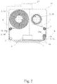
- FIG. 2 shows a schematic rear view of the proposed printer device of FIG. 1 in section
- FIG. 3 shows a perspective view of the proposed printer arrangement of FIG. 1 .
- FIG. 1 A proposed printer device for thermal printing or embossing of a carrier film 1 coated with a coloring matter on a substrate 2 is shown in a front view in FIG. 1 and in a rear view in FIG. 2 , in each case schematically and in section.
- FIG. 3 shows a corresponding perspective view.
- the carrier film 1 is a special kind of film for the thermal printing method which has preferably absorbed a coloring matter on one side. In a known manner, local heating of the carrier film 1 leads to a partial or complete detachment of the coloring matter from the carrier film 1 and to a corresponding deposit on the substrate 2 .
- the proposed printer device has a roller arrangement 3 for accommodating the carrier film 1 and for moving the carrier film 1 along a conveyor path 4 , stepper motors 5 a, b for driving the roller arrangement 3 , a thermal print head 6 for printing or embossing the coloring matter from the carrier film 1 onto the substrate 2 , and a swivel arrangement 8 , which can be deflected over a swivel range 7 , for engaging with a swivel roller 3 a of the roller arrangement 3 and for exerting a tensile force on the carrier film 1 .
- the swivel arrangement 8 which can be seen in FIG. 1 , is rigidly connected at its swivel end 8 a —with regard to the swivel movement—to the swivel roller 3 a , as is clearly shown in FIG. 3 .
- the proposed printer device is now characterized in that, with regard to an engagement with the carrier film 1 , the swivel roller 3 a is arranged along the conveyor path 4 directly adjacent to the thermal print head 6 . As can be seen from FIG. 3 , no structure, and in particular no deflector roller, which is in engagement with the carrier film 1 , is provided between the swivel roller 3 a and the thermal print head 6 .
- the swivel arrangement 8 exerts a substantially constant tensile force on the carrier film 1 over at least one part of the swivel range 7 , preferably over the whole swivel range 7 .
- the swivel arrangement 8 exerts a tensile force in a substantially constant tension direction 9 on the carrier film 1 over at least one part of the swivel range 7 , preferably over the whole swivel range 7 .
- a likewise substantially constant tensile force is imposed in the carrier film 1 .
- the swivel roller 3 a deflects the carrier film 1 as a result of its engagement by at least substantially 90°.
- the deflector roller 3 a especially deflects the carrier film 1 by substantially 90°.
- the printer device has a removable film magazine 10 , which film magazine 10 encompasses the roller arrangement 3 and the carrier film 1 .
- the film magazine 10 can be seen in the rear view of FIG. 2 and in the perspective view of FIG. 3 .
- the film magazine 10 is fixed to a base plate 11 of the printer device and that the stepper motors 5 a, b are fixed to the base plate 11 on a side of the base plate 11 opposite the film magazine 10 .
- This side opposite the film magazine 10 is shown in FIG. 1 , wherein the base plate 11 runs in the respective, here identical, planes of the diagram of FIG. 1 and FIG. 2 . This relationship can be clearly seen from FIG. 3 .
- the printer device has a sensor arrangement 12 , in particular for non-contact measurement of a deflection of the swivel arrangement 8 .
- the sensor arrangement 12 can have a Hall sensor 12 a for the non-contact measurement of the deflection.
- the swivel arrangement 8 has a dancer arm 14 which is elongated and mounted about a swivel point 13 . Accordingly, the swivel roller 3 a is then mounted about a roller swivel point 13 a , which has a common swivel axis with the swivel point 13 . Further, it is preferred that the swivel arrangement 8 engages with the roller arrangement 3 on an engagement side 14 a of the dancer arm 14 with regard to the swivel point 13 .
- the sensor arrangement 12 is set up to measure the deflection on a measuring side 14 b of the dancer arm 14 , which measuring side 14 b lies opposite the engagement side 14 a .
- the swivel point 13 divides the elongated dancer arm 14 into a section which forms the engagement side 14 a and into a further section which forms the measuring side 14 b.
- the dancer arm 14 is arranged on the side of the base plate 11 opposite the film magazine 10 . In this way, the film magazine 10 can be replaced without risking damage to the often sensitive sensor arrangement 12 .
- the measuring side 14 b of the dancer arm 14 covers a longer path than the engagement side 14 a of the dancer arm when the swivel arrangement 8 swivels.
- the sensitivity of the sensor arrangement 12 for measuring even very small deflections of the swivel arrangement 8 is improved, thus enabling the tensile force exerted to be limited to a particularly narrow range.
- this covering of a longer path can be achieved, for example, in that the measuring side 14 b is longer than the engagement side 14 a.
- the tensile force can then be kept substantially constant, particularly with regard to magnitude and direction, when, as preferred, the swivel range 7 defines a substantially linear swivel path 7 a , in particular of the dancer arm 14 .
- a substantially linear swivel path 7 a can be achieved by a limitation to short rotary movements.
- at least one end stop 15 which limits the swivel range 7 to the substantially linear swivel path 7 a , is provided.
- the swivel path 7 a runs substantially along the conveyor path 4 .
- the swivel path 7 a can also run substantially along a linear print section 4 a of the conveyor path 4 .
- a linear print section 4 a in this sense is understood to be a section of the conveyor path 4 which, firstly, runs substantially linearly and which, secondly, is used, at any rate in an extension thereof, for thermal printing or embossing on the substrate 2 by engagement with the thermal print head 6 .
- FIG. 1 illustrates this situation clearly.
- the swivel path 7 a is substantially shorter than the linear print section 4 a , but runs parallel to and along the linear print section 4 a.
- the printer arrangement has a spring arrangement 16 connected to the swivel arrangement 8 for exerting the tensile force.
- This spring arrangement 16 can be seen in FIG. 1 .
- the preferred variant, according to which the tensile force is aligned substantially collinearly with the swivel path 7 a can also be seen from FIG. 1 .
- the spring arrangement 16 comprises a wound torsion spring 16 a.
- the printer device has a motor regulator arrangement 17 for regulating a stepper motor speed of at least one of the stepper motors 5 a, b during the movement of the carrier film 1 . In this way, the speed, for example, with which the carrier film 1 is moved, can therefore be adjusted.
- the roller arrangement 3 has an unwind roller 3 b for unwinding the carrier film 1 and a rewind roller 3 c for rewinding the carrier film.
- the respective function of the unwind roller 3 b and the rewind roller 3 c can also be interchanged. Consequently, the appropriate arrangement can also be variable, in particular within a comparatively short period of time.
- the motor regulator arrangement 17 only regulates the stepper motor speed of the stepper motor 5 a to drive the unwind roller 3 b .
- stepper motor speed of the stepper motor 5 b to drive the rewind roller 3 c does not occur.
- the speed of the stepper motor 5 b can also be adjusted to stop the movement of the carrier film 1 or to set a different required set speed for this movement of the carrier film 1 .
- the stepper motor 5 a is exclusively provided to drive the unwind roller 3 b only for the above fine regulation by the motor regulator arrangement 17 .
- the printer device has a conveyor sensor arrangement 18 with a conveyor Hall sensor 18 a for measuring a movement of the carrier film 1 by the roller arrangement 3 .
- the roller sensor arrangement 3 can have a conveyor sensor deflector roller 3 d , on which the conveyor sensor arrangement 18 —as shown in FIG. 2 for example—is arranged. This enables an optical measurement which is subject to interference to be avoided.
Landscapes
- Physics & Mathematics (AREA)
- Optics & Photonics (AREA)
- Electronic Switches (AREA)
- Handling Of Continuous Sheets Of Paper (AREA)
Applications Claiming Priority (4)
| Application Number | Priority Date | Filing Date | Title |
|---|---|---|---|
| DE102015104766 | 2015-03-27 | ||
| DE102015104766.7A DE102015104766A1 (de) | 2015-03-27 | 2015-03-27 | Druckervorrichtung zum thermischen Drucken oder Prägen |
| DE102015104766.7 | 2015-03-27 | ||
| PCT/US2016/023588 WO2016160422A1 (en) | 2015-03-27 | 2016-03-22 | Printer device for thermal printing or embossing |
Publications (2)
| Publication Number | Publication Date |
|---|---|
| US20180029399A1 US20180029399A1 (en) | 2018-02-01 |
| US10696079B2 true US10696079B2 (en) | 2020-06-30 |
Family
ID=55650750
Family Applications (1)
| Application Number | Title | Priority Date | Filing Date |
|---|---|---|---|
| US15/554,973 Active 2036-11-16 US10696079B2 (en) | 2015-03-27 | 2016-03-22 | Printer device for thermal printing or embossing |
Country Status (5)
| Country | Link |
|---|---|
| US (1) | US10696079B2 (es) |
| EP (1) | EP3274182B1 (es) |
| DE (1) | DE102015104766A1 (es) |
| ES (1) | ES2765187T3 (es) |
| WO (1) | WO2016160422A1 (es) |
Families Citing this family (2)
| Publication number | Priority date | Publication date | Assignee | Title |
|---|---|---|---|---|
| CN108656715A (zh) * | 2018-07-13 | 2018-10-16 | 苏州迈为科技股份有限公司 | 一种用于太阳能电池片印刷的系统及印刷方法 |
| US11826956B2 (en) | 2019-10-04 | 2023-11-28 | Kana Holdings, LLC | System and method for providing three-dimensional features on large format print products |
Citations (18)
| Publication number | Priority date | Publication date | Assignee | Title |
|---|---|---|---|---|
| US4657418A (en) | 1984-01-16 | 1987-04-14 | Creative Associates | High capacity ribbon supply arrangement |
| EP0218500A1 (fr) | 1985-09-05 | 1987-04-15 | Societe D'applications Generales D'electricite Et De Mecanique Sagem | Cartouche de ruban d'impression pour machine imprimante, notamment pour impression par transfert thermique |
| US4666550A (en) * | 1986-02-24 | 1987-05-19 | Philip Morris Incorporated | Apparatus for producing a strip of laminated sheet material |
| US4739341A (en) * | 1985-06-19 | 1988-04-19 | Hitachi, Ltd. | Heat sensitive transfer recording apparatus and method |
| US4768890A (en) * | 1984-09-12 | 1988-09-06 | Kabushiki Kaisha Sato | Carbon ribbon transport guide device |
| US4849064A (en) | 1987-10-27 | 1989-07-18 | Pelikan Aktiengesellschaft | Hand-operated device for transferring a film from a carrier tape |
| US4909648A (en) | 1988-01-20 | 1990-03-20 | Datamax Corporation | Processor for forms with multi-format data |
| US5374007A (en) | 1993-01-22 | 1994-12-20 | Ncr Corporation | Ribbon supply apparatus |
| US5433539A (en) | 1993-01-21 | 1995-07-18 | Ncr Corporation | Control of media movement using a periodic calibration method and apparatus |
| US5670005A (en) | 1993-02-16 | 1997-09-23 | Minnesota Mining And Manufacturing Company | Method for manufacturing improved data display retroreflective sheeting |
| US5873662A (en) | 1997-12-03 | 1999-02-23 | Illinois Tool Works Inc. | Printer with dancer arm and reel brake and method therefor |
| WO2002002371A1 (de) | 2000-07-05 | 2002-01-10 | Bos Gmbh & Co. Kg | Laderaum für ein kraftfahrzeug |
| US6866077B2 (en) | 2002-07-17 | 2005-03-15 | Leister Process Technologies | Automatic welding machine |
| EP1538002A2 (en) | 2003-12-01 | 2005-06-08 | I.T.W. Espana, S.A. | Heat transfer printing device and printing method |
| US7052194B2 (en) * | 2003-04-22 | 2006-05-30 | Markem Technologies Limited | Apparatus and method for controlling a ribbon transport mechanism |
| WO2007077482A2 (en) | 2005-12-30 | 2007-07-12 | I.T.W. España, S.A. | Heat-transfer printing device |
| US20100172682A1 (en) * | 2007-05-31 | 2010-07-08 | Philip Hart | Tape drive |
| US20130113870A1 (en) * | 2010-07-22 | 2013-05-09 | Markem-Inaje Limited | Tape drive and method of operation of a tape drive |
Family Cites Families (1)
| Publication number | Priority date | Publication date | Assignee | Title |
|---|---|---|---|---|
| AU2001286048A1 (en) | 2000-09-11 | 2002-03-26 | Zipher Limited | Tape drive and printing apparatus |
-
2015
- 2015-03-27 DE DE102015104766.7A patent/DE102015104766A1/de not_active Withdrawn
-
2016
- 2016-03-22 US US15/554,973 patent/US10696079B2/en active Active
- 2016-03-22 EP EP16714159.7A patent/EP3274182B1/en active Active
- 2016-03-22 ES ES16714159T patent/ES2765187T3/es active Active
- 2016-03-22 WO PCT/US2016/023588 patent/WO2016160422A1/en not_active Ceased
Patent Citations (18)
| Publication number | Priority date | Publication date | Assignee | Title |
|---|---|---|---|---|
| US4657418A (en) | 1984-01-16 | 1987-04-14 | Creative Associates | High capacity ribbon supply arrangement |
| US4768890A (en) * | 1984-09-12 | 1988-09-06 | Kabushiki Kaisha Sato | Carbon ribbon transport guide device |
| US4739341A (en) * | 1985-06-19 | 1988-04-19 | Hitachi, Ltd. | Heat sensitive transfer recording apparatus and method |
| EP0218500A1 (fr) | 1985-09-05 | 1987-04-15 | Societe D'applications Generales D'electricite Et De Mecanique Sagem | Cartouche de ruban d'impression pour machine imprimante, notamment pour impression par transfert thermique |
| US4666550A (en) * | 1986-02-24 | 1987-05-19 | Philip Morris Incorporated | Apparatus for producing a strip of laminated sheet material |
| US4849064A (en) | 1987-10-27 | 1989-07-18 | Pelikan Aktiengesellschaft | Hand-operated device for transferring a film from a carrier tape |
| US4909648A (en) | 1988-01-20 | 1990-03-20 | Datamax Corporation | Processor for forms with multi-format data |
| US5433539A (en) | 1993-01-21 | 1995-07-18 | Ncr Corporation | Control of media movement using a periodic calibration method and apparatus |
| US5374007A (en) | 1993-01-22 | 1994-12-20 | Ncr Corporation | Ribbon supply apparatus |
| US5670005A (en) | 1993-02-16 | 1997-09-23 | Minnesota Mining And Manufacturing Company | Method for manufacturing improved data display retroreflective sheeting |
| US5873662A (en) | 1997-12-03 | 1999-02-23 | Illinois Tool Works Inc. | Printer with dancer arm and reel brake and method therefor |
| WO2002002371A1 (de) | 2000-07-05 | 2002-01-10 | Bos Gmbh & Co. Kg | Laderaum für ein kraftfahrzeug |
| US6866077B2 (en) | 2002-07-17 | 2005-03-15 | Leister Process Technologies | Automatic welding machine |
| US7052194B2 (en) * | 2003-04-22 | 2006-05-30 | Markem Technologies Limited | Apparatus and method for controlling a ribbon transport mechanism |
| EP1538002A2 (en) | 2003-12-01 | 2005-06-08 | I.T.W. Espana, S.A. | Heat transfer printing device and printing method |
| WO2007077482A2 (en) | 2005-12-30 | 2007-07-12 | I.T.W. España, S.A. | Heat-transfer printing device |
| US20100172682A1 (en) * | 2007-05-31 | 2010-07-08 | Philip Hart | Tape drive |
| US20130113870A1 (en) * | 2010-07-22 | 2013-05-09 | Markem-Inaje Limited | Tape drive and method of operation of a tape drive |
Non-Patent Citations (2)
| Title |
|---|
| International Preliminary Report on Patentability for copending international application No. PCT/US2016/023588, report dated Oct. 3, 2017 (6 pages). |
| Search Report and Written Opinion for copending International Application No. PCT/US2016/023588, dated Jun. 22, 2016, 10 pages. |
Also Published As
| Publication number | Publication date |
|---|---|
| DE102015104766A1 (de) | 2016-09-29 |
| US20180029399A1 (en) | 2018-02-01 |
| EP3274182A1 (en) | 2018-01-31 |
| ES2765187T3 (es) | 2020-06-08 |
| WO2016160422A1 (en) | 2016-10-06 |
| EP3274182B1 (en) | 2019-10-16 |
Similar Documents
| Publication | Publication Date | Title |
|---|---|---|
| JP7482175B2 (ja) | 印刷システムのためのエンドレスフレキシブルベルト | |
| US5751303A (en) | Printing medium management apparatus | |
| US5825374A (en) | Apparatus and method for advancing a web | |
| US8801306B2 (en) | Printing apparatus and method of printing with ribbon tension adjustment using movable ribbon guide members | |
| US5117241A (en) | Thermal printing apparatus with tensionless donor web during printing | |
| US8665301B2 (en) | Tape drive and method of operation of a tape drive | |
| GB2369326A (en) | Transfer printer which performs both continuous and intermittent printing functions | |
| CN103862863A (zh) | 通过使用带表面速度测量调节打印频率来改善图像质量 | |
| US10279608B2 (en) | Method for loading a web; apparatus for handling a web | |
| US5162815A (en) | Thermal printing apparatus with tensionless donor web during printing | |
| CN104822531B (zh) | 长条带状体的印刷方法及印刷装置 | |
| US10399370B2 (en) | Printing Apparatus | |
| JP2012061855A (ja) | 反射印刷 | |
| US10696079B2 (en) | Printer device for thermal printing or embossing | |
| JP2013512160A (ja) | 媒体輸送システム用のエッジガイド | |
| US10377128B2 (en) | Method for controlling a web in a printing apparatus | |
| GB2404896A (en) | Ribbon transport mechanism having tensioning means | |
| US20200001633A1 (en) | Dancer suspension assembly for a roll-to-roll printer | |
| US20180086584A1 (en) | Web transport assembly for transporting a web along a processing unit | |
| KR20080108979A (ko) | 화상 형성기용 급송 시스템 | |
| JP2013512161A (ja) | 強度調節可能なネスティング力を有するエッジガイド | |
| JPH06127063A (ja) | 感熱プリンタにおけるドナーウェブ位置決め装置 | |
| CN112969591B (zh) | 全息箔供应装置以及热箔压印机 | |
| JPH044528B2 (es) | ||
| JPH05162404A (ja) | 熱転写記録装置 |
Legal Events
| Date | Code | Title | Description |
|---|---|---|---|
| AS | Assignment |
Owner name: ILLINOIS TOOL WORKS INC., ILLINOIS Free format text: ASSIGNMENT OF ASSIGNORS INTEREST;ASSIGNORS:FRANZKE, THOMAS;SCHOBERL, LARS;BALLING, STEFAN;SIGNING DATES FROM 20160322 TO 20160401;REEL/FRAME:043465/0833 |
|
| FEPP | Fee payment procedure |
Free format text: ENTITY STATUS SET TO UNDISCOUNTED (ORIGINAL EVENT CODE: BIG.); ENTITY STATUS OF PATENT OWNER: LARGE ENTITY |
|
| STPP | Information on status: patent application and granting procedure in general |
Free format text: DOCKETED NEW CASE - READY FOR EXAMINATION |
|
| STPP | Information on status: patent application and granting procedure in general |
Free format text: NON FINAL ACTION MAILED |
|
| STPP | Information on status: patent application and granting procedure in general |
Free format text: RESPONSE TO NON-FINAL OFFICE ACTION ENTERED AND FORWARDED TO EXAMINER |
|
| STPP | Information on status: patent application and granting procedure in general |
Free format text: FINAL REJECTION MAILED |
|
| STPP | Information on status: patent application and granting procedure in general |
Free format text: RESPONSE AFTER FINAL ACTION FORWARDED TO EXAMINER |
|
| STCF | Information on status: patent grant |
Free format text: PATENTED CASE |
|
| MAFP | Maintenance fee payment |
Free format text: PAYMENT OF MAINTENANCE FEE, 4TH YEAR, LARGE ENTITY (ORIGINAL EVENT CODE: M1551); ENTITY STATUS OF PATENT OWNER: LARGE ENTITY Year of fee payment: 4 |