US10697471B2 - Gas turbine engine vanes - Google Patents
Gas turbine engine vanes Download PDFInfo
- Publication number
- US10697471B2 US10697471B2 US15/907,531 US201815907531A US10697471B2 US 10697471 B2 US10697471 B2 US 10697471B2 US 201815907531 A US201815907531 A US 201815907531A US 10697471 B2 US10697471 B2 US 10697471B2
- Authority
- US
- United States
- Prior art keywords
- vanes
- aerodynamic
- strut
- gas turbine
- vane
- Prior art date
- Legal status (The legal status is an assumption and is not a legal conclusion. Google has not performed a legal analysis and makes no representation as to the accuracy of the status listed.)
- Active, expires
Links
- 238000011144 upstream manufacturing Methods 0.000 claims abstract description 22
- 230000002250 progressing effect Effects 0.000 claims 1
- 238000002485 combustion reaction Methods 0.000 description 3
- 238000009792 diffusion process Methods 0.000 description 3
- 239000012530 fluid Substances 0.000 description 3
- 230000001141 propulsive effect Effects 0.000 description 3
- 230000002829 reductive effect Effects 0.000 description 3
- 230000003247 decreasing effect Effects 0.000 description 2
- 230000003068 static effect Effects 0.000 description 2
- PINRUEQFGKWBTO-UHFFFAOYSA-N 3-methyl-5-phenyl-1,3-oxazolidin-2-imine Chemical compound O1C(=N)N(C)CC1C1=CC=CC=C1 PINRUEQFGKWBTO-UHFFFAOYSA-N 0.000 description 1
- 230000002411 adverse Effects 0.000 description 1
- 238000003491 array Methods 0.000 description 1
- 230000009286 beneficial effect Effects 0.000 description 1
- 230000006835 compression Effects 0.000 description 1
- 238000007906 compression Methods 0.000 description 1
- 239000004020 conductor Substances 0.000 description 1
- 230000001627 detrimental effect Effects 0.000 description 1
- 238000009826 distribution Methods 0.000 description 1
- 239000000446 fuel Substances 0.000 description 1
- 230000000670 limiting effect Effects 0.000 description 1
- 238000005461 lubrication Methods 0.000 description 1
- 239000000203 mixture Substances 0.000 description 1
- 230000004048 modification Effects 0.000 description 1
- 238000012986 modification Methods 0.000 description 1
Images


Classifications
-
- F—MECHANICAL ENGINEERING; LIGHTING; HEATING; WEAPONS; BLASTING
- F04—POSITIVE - DISPLACEMENT MACHINES FOR LIQUIDS; PUMPS FOR LIQUIDS OR ELASTIC FLUIDS
- F04D—NON-POSITIVE-DISPLACEMENT PUMPS
- F04D29/00—Details, component parts, or accessories
- F04D29/40—Casings; Connections of working fluid
- F04D29/52—Casings; Connections of working fluid for axial pumps
- F04D29/54—Fluid-guiding means, e.g. diffusers
- F04D29/541—Specially adapted for elastic fluid pumps
- F04D29/542—Bladed diffusers
- F04D29/544—Blade shapes
-
- F—MECHANICAL ENGINEERING; LIGHTING; HEATING; WEAPONS; BLASTING
- F01—MACHINES OR ENGINES IN GENERAL; ENGINE PLANTS IN GENERAL; STEAM ENGINES
- F01D—NON-POSITIVE DISPLACEMENT MACHINES OR ENGINES, e.g. STEAM TURBINES
- F01D9/00—Stators
- F01D9/02—Nozzles; Nozzle boxes; Stator blades; Guide conduits, e.g. individual nozzles
- F01D9/04—Nozzles; Nozzle boxes; Stator blades; Guide conduits, e.g. individual nozzles forming ring or sector
- F01D9/041—Nozzles; Nozzle boxes; Stator blades; Guide conduits, e.g. individual nozzles forming ring or sector using blades
-
- F—MECHANICAL ENGINEERING; LIGHTING; HEATING; WEAPONS; BLASTING
- F01—MACHINES OR ENGINES IN GENERAL; ENGINE PLANTS IN GENERAL; STEAM ENGINES
- F01D—NON-POSITIVE DISPLACEMENT MACHINES OR ENGINES, e.g. STEAM TURBINES
- F01D25/00—Component parts, details, or accessories, not provided for in, or of interest apart from, other groups
- F01D25/16—Arrangement of bearings; Supporting or mounting bearings in casings
- F01D25/162—Bearing supports
-
- F—MECHANICAL ENGINEERING; LIGHTING; HEATING; WEAPONS; BLASTING
- F02—COMBUSTION ENGINES; HOT-GAS OR COMBUSTION-PRODUCT ENGINE PLANTS
- F02C—GAS-TURBINE PLANTS; AIR INTAKES FOR JET-PROPULSION PLANTS; CONTROLLING FUEL SUPPLY IN AIR-BREATHING JET-PROPULSION PLANTS
- F02C3/00—Gas-turbine plants characterised by the use of combustion products as the working fluid
- F02C3/04—Gas-turbine plants characterised by the use of combustion products as the working fluid having a turbine driving a compressor
- F02C3/06—Gas-turbine plants characterised by the use of combustion products as the working fluid having a turbine driving a compressor the compressor comprising only axial stages
-
- F—MECHANICAL ENGINEERING; LIGHTING; HEATING; WEAPONS; BLASTING
- F01—MACHINES OR ENGINES IN GENERAL; ENGINE PLANTS IN GENERAL; STEAM ENGINES
- F01D—NON-POSITIVE DISPLACEMENT MACHINES OR ENGINES, e.g. STEAM TURBINES
- F01D5/00—Blades; Blade-carrying members; Heating, heat-insulating, cooling or antivibration means on the blades or the members
- F01D5/12—Blades
- F01D5/14—Form or construction
- F01D5/141—Shape, i.e. outer, aerodynamic form
- F01D5/145—Means for influencing boundary layers or secondary circulations
-
- F—MECHANICAL ENGINEERING; LIGHTING; HEATING; WEAPONS; BLASTING
- F05—INDEXING SCHEMES RELATING TO ENGINES OR PUMPS IN VARIOUS SUBCLASSES OF CLASSES F01-F04
- F05D—INDEXING SCHEME FOR ASPECTS RELATING TO NON-POSITIVE-DISPLACEMENT MACHINES OR ENGINES, GAS-TURBINES OR JET-PROPULSION PLANTS
- F05D2220/00—Application
- F05D2220/30—Application in turbines
- F05D2220/32—Application in turbines in gas turbines
-
- F—MECHANICAL ENGINEERING; LIGHTING; HEATING; WEAPONS; BLASTING
- F05—INDEXING SCHEMES RELATING TO ENGINES OR PUMPS IN VARIOUS SUBCLASSES OF CLASSES F01-F04
- F05D—INDEXING SCHEME FOR ASPECTS RELATING TO NON-POSITIVE-DISPLACEMENT MACHINES OR ENGINES, GAS-TURBINES OR JET-PROPULSION PLANTS
- F05D2240/00—Components
- F05D2240/10—Stators
- F05D2240/12—Fluid guiding means, e.g. vanes
-
- F—MECHANICAL ENGINEERING; LIGHTING; HEATING; WEAPONS; BLASTING
- F05—INDEXING SCHEMES RELATING TO ENGINES OR PUMPS IN VARIOUS SUBCLASSES OF CLASSES F01-F04
- F05D—INDEXING SCHEME FOR ASPECTS RELATING TO NON-POSITIVE-DISPLACEMENT MACHINES OR ENGINES, GAS-TURBINES OR JET-PROPULSION PLANTS
- F05D2240/00—Components
- F05D2240/10—Stators
- F05D2240/12—Fluid guiding means, e.g. vanes
- F05D2240/122—Fluid guiding means, e.g. vanes related to the trailing edge of a stator vane
-
- Y—GENERAL TAGGING OF NEW TECHNOLOGICAL DEVELOPMENTS; GENERAL TAGGING OF CROSS-SECTIONAL TECHNOLOGIES SPANNING OVER SEVERAL SECTIONS OF THE IPC; TECHNICAL SUBJECTS COVERED BY FORMER USPC CROSS-REFERENCE ART COLLECTIONS [XRACs] AND DIGESTS
- Y02—TECHNOLOGIES OR APPLICATIONS FOR MITIGATION OR ADAPTATION AGAINST CLIMATE CHANGE
- Y02T—CLIMATE CHANGE MITIGATION TECHNOLOGIES RELATED TO TRANSPORTATION
- Y02T50/00—Aeronautics or air transport
- Y02T50/60—Efficient propulsion technologies, e.g. for aircraft
-
- Y02T50/671—
-
- Y02T50/673—
Definitions
- This disclosure relates to a gas turbine engine, for example ducts and/or vanes within a gas turbine engine, for example within a compressor section of a gas turbine engine.
- a gas turbine engine conventionally has one or more ducts, which may be annular ducts and/or may be provided in a core of a gas turbine engine.
- one such duct may be provided between compressor sections of a gas turbine engine, such as between an intermediate pressure compressor section and a high pressure compressor section.
- Such ducts may comprise structural struts that maintain the structural rigidity of the engine, for example in the region of the duct.
- the structural struts are typically non-lifting, i.e. they do not provide any appreciable flow-turning in use (for example at engine cruise conditions).
- the flow through the duct in use has nominally zero swirl (for example no circumferential component) because any swirl is removed upstream of the duct by a row of stator vanes, and the structural struts are thus not cambered, and typically have a symmetrical cross-section.
- a gas turbine engine defining axial, radial and circumferential directions.
- the gas turbine engine comprises a duct defined by an axially extending radially inner wall and an axially extending radially outer wall.
- An annular array of turning vanes is provided in the duct, the array comprising a set of cambered aerodynamic vanes and a set of cambered strut-vanes, the strut-vanes having trailing edges that extend further axially downstream than trailing edges of the aerodynamic vanes.
- a tangent to a mean camber line at the trailing edge of the strut-vanes is more closely aligned to the axial direction than is a tangent to a mean camber line at the trailing edge of the aerodynamic vanes.
- the leading edges of the strut-vanes are axially upstream of the trailing edges of the aerodynamic vanes.
- the mean camber line of the strut-vanes is substantially the same as the mean camber line of at least some of the aerodynamic vanes for axial locations between the leading and trailing edges of the aerodynamic vanes.
- the mean camber line of the strut-vanes may be substantially the same as the mean camber line of all of the aerodynamic vanes for axial locations between the leading and trailing edges of the aerodynamic vanes.
- the mean camber line of the strut-vanes may be substantially the same as the average of the mean camber lines of the aerodynamic vanes adjacent the suction surface and the pressure surface of the strut-vane for axial locations between the leading and trailing edges of the aerodynamic vanes.
- the strut-vanes may be said to be cambered both upstream and downstream of the axial location of the trailing edges of the aerodynamic vanes, i.e. the camber line may be curved (for example towards the axial direction, i.e.
- The-pressure surface and suction surface of the strut-vanes may be non-symmetric both upstream and downstream of the axial location of the trailing edges of the aerodynamic vanes, for example from the leading edge to substantially the trailing edge of the strut-vane.
- the mean camber line may be the line defined by the midpoints between the suction surface and the pressure surface along the chord of the vane.
- the mean camber line may be the mean camber line at a given radial (or spanwise) position (for example, a given radial position between 5% and 95% of the vane span), or averaged over the span (or a portion of the span, such as 5% to 95%) of the vane.
- the mean camber line at a given radius may be determined by taking a cross-section at that radius, for example perpendicular to a radial direction.
- the duct may be said to be an annular duct.
- a cross-section through the duct at a given axial location, and perpendicular to the axial direction, may be annular.
- the term axially downstream may be defined as being in the direction from a compressor to a turbine of a gas turbine engine.
- axially upstream may be defined as being in the direction from a turbine to a compressor of a gas turbine engine.
- the aerodynamic vanes and the strut-vanes may be said to be axially overlapping. At least a part (for example the leading edge and/or at least a part of the pressure surface and/or suction surface) of each strut-vane may be provided between the suction surface of one aerodynamic vane and the pressure surface of another aerodynamic vane.
- the strut-vanes may have greater chord length than the aerodynamic vanes.
- a cambered vane may be a vane in which the mean camber line is curved and/or in which a tangent to the mean camber line changes direction along the camber line.
- the mean camber line may turn towards the axial direction in a downstream direction.
- both the aerodynamic vanes and the strut-vanes may provide flow turning in use.
- the strut vanes may be referred to as aerodynamic strut-vanes.
- Arrangements for example of aerodynamic vanes and strut-vanes as described and/or claimed herein may allow for a shorter than conventional duct. Such arrangements may have minimal or substantially no detrimental impact on engine efficiency and/operability.
- the strut-vanes and the aerodynamic vanes may both contribute towards the flow turning.
- the strut-vanes may continue to provide flow turning (for example towards the axial direction) downstream of the trailing edges of the aerodynamic vanes.
- the flow direction (and/or the tangent to the camber line) need not be parallel to, or even substantially parallel to, the axial direction at the trailing edge of the aerodynamic vanes.
- Undesirable mechanical forcing may be avoided or at least maintained at an acceptable level, for example by the described and/or claimed shaped aerodynamic vanes and/or strut-vanes.
- the described and/or claimed arrangements may control (for example substantially eliminate) any increase in upstream static pressure that may otherwise result from the presence of the struts.
- a plurality of aerodynamic vanes may be provided between two circumferentially adjacent strut-vanes.
- the mean camber line of the strut-vanes may be substantially the same as the mean camber line of the aerodynamic vanes (including, for example, all or at least some of the aerodynamic vanes) for axial locations between the leading and trailing edges of the aerodynamic vanes.
- All of the aerodynamic vanes may be the same as each other.
- at least some of the aerodynamic blades may be different to each other.
- the mean camber line of the strut-vanes may be substantially the same as the mean camber line of at least some of the aerodynamic vanes for axial locations between the leading and trailing edges of the aerodynamic vanes.
- the gas turbine engine may comprise a first compressor section and a second compressor section that is axially downstream of the first compressor section.
- the duct may be provided between the first compressor section and the second compressor section.
- Each of the radially inner wall and radially outer wall may extend axially downstream and radially inboard as it extends away from the first compressor section towards the second compressor section.
- the first compressor section may comprise rotor blades that are connected to a first shaft that is also connected to a first turbine.
- the second compressor section may comprise rotor blades that are connected to a second shaft that is also connected to a second turbine.
- the rotational speed of the second shaft may be higher than the rotational speed of the second shaft.
- the first shaft may be referred to as a low pressure shaft and/or the first compressor section may be referred to as a low (or intermediate) pressure compressor.
- the second shaft may be referred to as a high pressure shaft and/or the first compressor section may be referred to as a high pressure compressor.
- the first compressor section may comprise at least two stages, each stage comprising a rotor row and a stator row.
- the second compressor section may comprise at least two stages, each stage comprising a rotor row and a stator row.
- Immediately upstream of the annular array of turning vanes (and/or immediately upstream of the duct) may be a rotor row of the first compressor section.
- Immediately downstream of the annular array of turning vanes (and/or immediately downstream of the duct) may be a rotor row of the second compressor section.
- the axial position of the leading edges of the aerodynamic vanes may be the same as the axial position of the leading edge of the strut-vanes. This may mean that the axial position of the leading edges of the aerodynamic vanes may be substantially the same as the axial position of the leading edge of the strut-vanes, for example the axial position of the leading edges may be within 1%, 5% or 10% of the chord length of a strut-vane.
- the tangent to the mean camber line of the aerodynamic vanes may not be parallel to the axial direction at the trailing edge.
- the tangent to the mean camber line of the aerodynamic vanes may be in the range of from 5 degrees to 40 degrees from the axial direction.
- the tangent to the mean camber line of the vanes of the strut-vanes at the trailing edge may be in the range of from 0 degrees to 15 degrees from the axial direction.
- the geometry of the strut-vanes may be such that the mean camber line turns towards the axial direction downstream of the trailing edge (that is, downstream of the axial position of the trailing edge) of the aerodynamic vanes.
- the mean camber line of the strut-vanes may turn towards the axial direction by an angle in the range of from 5 degrees and 30 degrees between the axial position of the trailing edge of the aerodynamic vanes and the trailing edge of the strut-vanes.
- the only features that extend between the radially inner wall and radially outer wall of the duct may be aerodynamic vanes or strut-vanes.
- the strut-vanes may be stronger (for example they may be able to withstand greater load (for example before breaking) and/or may pass greater load between the radially inner wall and the radially outer wall during use, individually and/or collectively) than the aerodynamic vanes.
- a plurality of aerodynamic vanes may be provided in a gap defined by a suction surface of one strut-vane and a pressure surface of another strut-vane.
- the solidity of the aerodynamic vanes may be constant across such a gap.
- the solidity of the aerodynamic vanes in the gap that are closest to the suction surface may be higher than the solidity of aerodynamic vanes in the gap that are closest to the pressure surface.
- the solidity of the aerodynamic vanes may increase across the gap from the pressure surface of the strut-vane that defines the gap to the suction surface of the other strut-vane that defines the gap in any desired manner or pattern.
- the solidity of the aerodynamic vanes may increase continuously across the entire gap from the pressure surface of the strut-vane that defines the gap to the suction surface of the other strut-vane that defines the gap.
- the solidity of the aerodynamic vanes may, for example, increase uniformly across the gap from the pressure surface of the strut-vane that defines the gap to the suction surface of the other strut-vane that defines the gap.
- the solidity of the aerodynamic vanes may, for example, be uniform across at least a portion of the gap.
- the solidity of the aerodynamic vanes may be uniform over a central portion of the gap, with only those aerodynamic vanes (for example 2, 3, 4 or 5) closest to the suction surface having higher solidity and/or only those aerodynamic vanes (for example 2, 3, 4 or 5) closest to the pressure surface having lower solidity.
- the pitch (or spacing) of the aerodynamic vanes may be reduced towards (or adjacent) the pressure surface of the strut-vane defining the gap and/or increased towards (or adjacent) the suction surface of the other strut-vane defining the gap.
- the spacing (or pitch) between the two aerodynamic vanes that are closest to the suction surface of the strut-vane that defines the gap may be greater than the spacing between the two aerodynamic vanes that are closest to the pressure surface of the strut-vane that defines the gap.
- the chord length of the aerodynamic vanes may be increased towards (or adjacent) the pressure surface of the strut-vane defining the gap and/or decreased towards (or adjacent) the suction surface of the other strut-vane defining the gap.
- the chord length of the aerodynamic vane that is closest to the suction surface of the strut-vane that defines the gap may be smaller than the chord length of the aerodynamic vane that is closest to the pressure surface of the strut-vane that defines the gap.
- the spacing between all of the aerodynamic vanes may be uniform across the gap.
- the chord length of the aerodynamic vanes may vary across the gap, for example with the vane or vanes closest to the suction surface of the strut-vane that defines the gap having a shorter chord or chords than the vane or vanes closest to the pressure surface of the other strut-vane that defines the gap.
- All of the aerodynamic vanes in the gap may have the same chord length.
- the spacing between the aerodynamic vanes may vary across the gap, for example with the vane or vanes closest to the suction surface of the strut-vane that defines the gap being spaced further from each other than the vane or vanes closest to the pressure surface of the other strut-vane that defines the gap.
- the term solidity means the space to chord ratio of the vanes.
- the solidity for a particular vane may be defined as the average spacing between that vane and the two adjacent vanes (which may, for example, both be aerodynamic vanes or may be one aerodynamic vane and one strut-vane) divided by the vane chord.
- the spacing may be referred to as the pitch.
- the spacing may be the space between the camber lines of the vanes. Where the camber lines of the vanes are not the same, this may be the average spacing and/or the spacing at a particular point, such as the leading edge, trailing edge or mid-chord.
- Control of the solidity as described and/or claimed herein may be effective in controlling the diffusion factor.
- the diffusion factor may be used to characterize the velocity change along the suction surface of a vane, thereby providing a measure of the diffusion and adverse pressure gradient to which the boundary layer on the suction surface is subjected. Control of this parameter may be important as it may be a limiting factor in the achievable level of turning of a given vane.
- the pitch of the aerodynamic vanes may be reduced towards (or adjacent) the pressure surface of the strut-vane defining the gap and/or increased towards (or adjacent) the suction surface of the other strut-vane defining the gap.
- the spacing between the two aerodynamic vanes that are closest to the suction surface of the strut-vane that defines the gap may be greater than the spacing between the two aerodynamic vanes that are closest to the pressure surface of the strut-vane that defines the gap.
- the chord length of the aerodynamic vanes may be increased towards (or adjacent) the pressure surface of the strut-vane defining the gap and/or decreased towards (or adjacent) the suction surface of the other strut-vane defining the gap.
- the chord length of the aerodynamic vane that is closest to the suction surface of the strut-vane that defines the gap may be smaller than the chord length of the aerodynamic vane that is closest to the pressure surface of the strut-vane that defines the gap.
- the mean camber line may be same for all vanes, at least over overlapping axial portions.
- the tangent to a mean camber line at the trailing edge of an aerodynamic vane that is closest to the pressure surface of the strut-vane that defines the gap may be closer to the axial direction than is the tangent to a mean camber line at the trailing edge of an aerodynamic vane that is closest to the suction surface of the strut-vane that defines the gap.
- the tangent to a mean camber line at the leading edge of an aerodynamic vane that is closest to the pressure surface of the strut-vane that defines the gap may be closer to the axial direction than is the tangent to a mean camber line at the leading edge of an aerodynamic vane that is closest to the suction surface of the strut-vane that defines the gap.
- the tangent to the mean camber line may vary gradually (or uniformly) across the gap, or locally adjacent the pressure and/or suction surfaces of the respective strut-vanes defining the gap. Differences in the direction of the tangents to the mean camber line at the leading and/or trailing edge across the gap may result from different cambers and/or different orientations.
- At least one of the strut-vanes may have one or more components of an auxiliary gas turbine engine system passing therethrough, for example so as to pass from and/or communicate between a region outside the radially outer wall of the duct and a region inside the radially inner wall of the duct.
- Such components may be, for example, parts of a fluid system (such as a hydraulic and/or lubrication system) and/or an electrical system (such as electrical conductors, which may be in the form of cables).
- At least one of the strut-vanes may have a line-of-sight from the radially outer wall of the duct to the radially inner wall of the duct, for example to allow undeformable components (such as a drive shaft) to pass therethrough.
- the strut-vanes may have any suitable shape.
- the strut-vanes may have a maximum thickness in the range of from 10% to 30% of their chord and/or a chordwise location of the maximum thickness position in the range of from 20% to 50% of the total chord length from the leading edge.
- the suction surface of a strut vane may be convex along its entire span, for example a complex convex curve.
- the pressure surface of a strut vane may be generally concave, for example it may all be concave or it may comprise concave and convex portions.
- Such geometry may be, for example, an average over the span of the strut-vane and/or at one or more radial positions, for example at all radial positions between 10% and 90% of the strut-vane span from the root.
- Both the aerodynamic vanes and the strut-vanes may be aerofoils.
- the thickness of the trailing edges of both the aerodynamic vanes and the strut-vanes may be less than 5 mm, for example less than 2 mm, for example less than 1 mm.
- Gas turbine engines as described and/or claimed herein may be of any suitable form.
- the gas turbine engine may be an aero gas turbine engine for use on aircraft, such as a turbofan gas turbine engine, for example.
- a turbofan gas turbine engine for example.
- Such an engine may be a geared turbofan gas turbine engine, in which the fan stage is driven from a turbine via a gearbox, in order to reduce (or increase) the rotational speed of the fan stage compared with the driving turbine stage(s).
- FIG. 1 is a sectional side view of a gas turbine engine in accordance with the present disclosure
- FIG. 2 is a side view of a gas turbine engine duct with vanes in accordance with the present disclosure
- FIG. 3 is a cross-section through an array of turning vanes provided in a duct in accordance with the present disclosure
- FIG. 4 is an enlarged cross-section through aerodynamic vanes and a strut-vane in accordance with the present disclosure
- FIGS. 5 a to 5 d are graphs showing examples of possible flow turning distributions that may be provided by strut-vanes in accordance with the present disclosure
- FIG. 6 is a cross-section through an array of turning vanes provided in a duct in accordance with the present disclosure
- FIG. 7 is a cross-section through an array of turning vanes provided in a duct in accordance with the present disclosure.
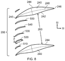
- FIG. 8 is a cross-section through an array of turning vanes provided in a duct in accordance with the present disclosure.
- a gas turbine engine is generally indicated at 10 , having a principal and rotational axis 11 .
- the engine 10 comprises, in axial flow series, an air intake 12 , a propulsive fan 13 , an intermediate pressure compressor 14 , a high-pressure compressor 15 , combustion equipment 16 , a high-pressure turbine 17 , an intermediate pressure turbine 18 , a low-pressure turbine 19 and an exhaust nozzle 20 .
- a nacelle 21 generally surrounds the engine 10 and defines both the intake 12 and the exhaust nozzle 20 .
- the gas turbine engine 10 works in the conventional manner so that air entering the intake 12 is accelerated by the fan 13 to produce two air flows: a first air flow into the intermediate pressure compressor 14 and a second air flow which passes through a bypass duct 22 to provide propulsive thrust.
- the intermediate pressure compressor 14 compresses the air flow directed into it before delivering that air to the high pressure compressor 15 where further compression takes place.
- the compressed air exhausted from the high-pressure compressor 15 is directed into the combustion equipment 16 where it is mixed with fuel and the mixture combusted.
- the resultant hot combustion products then expand through, and thereby drive the high, intermediate and low-pressure turbines 17 , 18 , 19 before being exhausted through the nozzle 20 to provide additional propulsive thrust.
- the high 17 , intermediate 18 and low 19 pressure turbines drive respectively the high pressure compressor 15 , intermediate pressure compressor 14 and fan 13 , each by suitable interconnecting shaft.
- the gas turbine engine 10 comprises at least one duct, which may be an annular duct, defining a flow path for working fluid.
- a duct is the duct 100 shown in FIG. 1 that extends between the intermediate pressure compressor 14 (for example from the exit of the intermediate pressure compressor 14 ) and the high pressure compressor 15 (for example to the inlet of the high pressure compressor 15 ).
- Such a duct 100 comprises turning vanes 200 , which may be stationary vanes 200 , which may be referred to as stationary lifting vanes 200 .
- the gas turbine engine 10 and/or the duct 100 (described in more detail elsewhere herein) and/or the turning vanes 200 (described in more detail elsewhere herein) shown in FIG. 1 may be in accordance with examples of the present disclosure, aspects of which are described by way of example only in relation to FIGS. 2 to 8 .
- gas turbine engines to which the present disclosure may be applied may have related or alternative configurations.
- such engines may have an alternative number of interconnecting shafts (e.g. two) and/or an alternative number of compressors and/or turbines.
- the engine may (or may not) comprise a gearbox provided in the drive train from a turbine to a compressor and/or fan.
- the described example relates to a turbofan engine, the disclosure may apply, for example, to any type of gas turbine engine, such as a turbojet, open rotor (in which the fan stage is not surrounded by a nacelle) or turboprop engine, for example.
- the geometry of the gas turbine engine 10 is defined by a conventional axis system, comprising an axial direction 30 (which is aligned with the rotational axis 11 ), a radial direction 40 , and a circumferential direction 50 (shown perpendicular to the page in the FIG. 1 view).
- the axial, radial and circumferential directions 30 , 40 , 50 are mutually perpendicular.
- FIG. 2 shows a side view (which may be defined as a view looking along a circumferential direction 50 ) of the duct 100 , which extends between a radially inner wall 102 and a radially outer wall 104 , in greater detail.
- the duct 100 has a length L, which may be defined as a length from the exit of the intermediate pressure compressor 14 to the inlet of the high pressure compressor 15 .
- the length L may be shorter than equivalent ducts in conventional engines, at least in part because of the arrangement of the annular array of turning vanes 200 described and/or claimed herein.
- the duct 100 extends in an axial direction 30 .
- At least a part of the duct 100 moves radially inboard with downstream axial position.
- the duct 100 may be described as an annular duct 100 .
- the duct 100 may be referred to as on “s-shaped” duct or a “swan-necked” duct.
- the duct 100 has an array of turning vanes 200 provided therein.
- the array of turning vanes 200 comprises aerodynamic vanes 220 and strut-vanes 240 .
- An example of such an array of turning vanes 200 is shown in FIG. 3 , with a close-up view of a strut-vane 240 and neighbouring aerodynamic vanes 220 in FIG. 4 .
- the cross-sections shown in FIGS. 3, 4, 6, 7 and 8 may be taken, for example, along surface defined by the radial midpoints between the inner and outer walls 102 , 104 of the duct 100 , as indicated by the line 110 shown in FIG. 2 .
- the aerodynamic vanes 220 are provided in a gap 260 defined by a suction surface 244 of on strut-vane 240 and a pressure surface 242 of an adjacent strut-vane 240 .
- a suction surface 244 of on strut-vane 240 and a pressure surface 242 of an adjacent strut-vane 240 may be provided in the gap 260 , for example 2, 3, 4, 5, 6, 7, 8, 9, 10, 11, 12, 13, 14, 15 or more than 15.
- an engine 10 may comprise on the order of 8-12 strut-vanes 240 and/or 80-120 aerodynamic vanes 220 .
- the strut-vanes 240 may be structural, for example providing stiffness and/or rigidity to the engine 10 in the region of the duct 100 . Additionally or alternatively, the strut-vane 240 may be used to pass components of one or more auxiliary services across the duct 100 , such as a drive shaft 270 or a conduit (such as an electrical or fluid conduit) 275 as shown by way of example in FIG. 4 .
- the axial position of the leading edges 245 of the strut-vanes 240 are axially upstream of the trailing edges 226 of the aerodynamic vanes 220 , for example axially upstream of the trailing edges 226 of the adjacent aerodynamic vanes 220 .
- the axial position of the leading edges 245 of the strut-vanes 240 may be axially between the leading edges 225 and the trailing edges 226 of the aerodynamic vanes 220 , for example at least of the adjacent aerodynamic vanes 220 .
- the axial position of the leading edges 245 of the strut-vanes 240 may be the same as the axial position of the leading edges 225 of the aerodynamic vanes 220 , as in the examples of FIGS. 3 and 6 to 8 .
- the axial position of the trailing edges 246 of the strut-vanes 240 are downstream of the axial position of the trailing edges 226 of the aerodynamic vanes 220 .
- the chord length (indicated by the letter C in FIG. 4 ) of the strut-vanes 240 is greater than the chord length of the aerodynamic vanes 220 .
- the strut-vanes 240 and aerodynamic vanes 220 may have any desired shape.
- the location of the maximum thickness (T in FIG. 4 ) of a strut-vane may be at less than 60%, for example between 20% and 50%, of the total chord length C from the leading edge 245 .
- the maximum thickness ‘t’ may be in the range of from 10% to 30% of the chord ‘C’. Whilst only exemplary, this may be beneficial in providing good aerodynamic performance (for example efficient flow turning) whilst meeting any structural (for example load bearing) requirements and/or providing sufficient space to pass auxiliary components therethrough.
- the strut-vanes 240 are turning vanes.
- the strut-vanes 240 have a camber line 248 that may be curved.
- the camber line 248 may be curved at axial positions both upstream and downstream of the axial location of the trailing edge 226 of the aerodynamic vane 220 .
- the strut-vane 240 may provide flow turning both upstream and downstream of the axial location of the trailing edge 226 of the aerodynamic vane 220 .
- FIG. 3 shows angle ⁇ 1 , ⁇ 2 , ⁇ 3 , ⁇ 1 represents the angle of the mean camber line 248 of the strut-vanes 240 (and in the FIG. 3 example the aerodynamic vanes 220 ) relative to the axial direction 30 at the leading edge 245 .
- ⁇ 2 represents the angle of the mean camber line 228 of the aerodynamic vanes 220 relative to the axial direction 30 at their trailing edge 226 .
- ⁇ 3 represents the angle of the mean camber line 248 of the strut-vanes 240 relative to the axial direction 30 at their trailing edge 246 .
- ⁇ 1 may be defined as the swirl angle (for example at mid-span) of the flow (at a representative operating condition of the engine, for example at cruise conditions) at entry to the annular array of turning vanes 200 ;
- ⁇ 2 may be defined as the swirl angle (for example at mid-span) of the flow (at a representative operating condition of the engine, for example at cruise conditions) at the trailing edge 226 of the aerodynamic vanes 220 ;
- ⁇ 3 may be defined as the swirl angle (for example at mid-span) of the flow (at a representative operating condition of the engine, for example at cruise conditions) at the trailing edge 246 of the strut-vanes 240 .
- ⁇ 1 , ⁇ 2 , ⁇ 3 may be as described and/or claimed herein.
- ⁇ 1 may be in the range of from 30 degrees and 70 degrees
- ⁇ 2 may be in the range of from 5 degrees and 40 degrees
- ⁇ 3 may be in the range of from 0 degrees and 15 degrees.
- the flow may comprise substantially no swirl (that is, it may have substantially no circumferential component) downstream of the strut-vanes 240 , as in the FIG. 3 example.
- the camber line 248 of the strut vane may be such that significant flow turning occurs downstream of the axial position of the trailing edge of the aerodynamic vanes 220 .
- the value of ⁇ 2 - ⁇ 3 may be in the range of from 5 degrees to 30 degrees.
- the strut-vane 240 shown in FIG. 4 has an aerodynamic vane 220 superimposed thereon.
- the camber line 248 of the strut-vane 240 may be the same as the camber line 228 of the aerodynamic vane 220 in the axial regions where the aerodynamic vanes 220 and strut-vanes 240 overlap, for example between the leading edge 225 and trailing edge 226 of the aerodynamic vanes 220 .
- the vanes 220 are identical (as in the arrangements of FIGS.
- the camber line 248 of the strut-vane 240 may be the same as the camber line 228 of the aerodynamic vane 220 that is closest to the pressure surface 242 or the suction surface 244 of the strut-vane, or may be the average of the camber lines 228 of the aerodynamic vanes 220 that is closest to the pressure surface 242 and the suction surface 244 of the strut-vane in the regions of axial overlap, for example.
- FIGS. 5 a to 5 d show examples of how the percentage of tangential momentum (which may be a measure of swirl angle) may vary along a streamline in the duct 100 against the percentage distance along a strut-vane 240 , for example against the percentage along the camber line 280 .
- the tangential momentum may be removed linearly (as in FIG. 5 a ), or the removal may be biased towards the upstream portion (as in FIG. 5 b ), downstream portion (as in FIG. 5 c ) or central portion (as in FIG. 5 d ).
- FIGS. 5 a to 5 d show examples of how the percentage of tangential momentum (which may be a measure of swirl angle) may vary along a streamline in the duct 100 against the percentage distance along a strut-vane 240 , for example against the percentage along the camber line 280 .
- the tangential momentum may be removed linearly (as in FIG. 5 a ), or the removal may be biased towards the up
- the percentage of tangential momentum is the tangential momentum remaining in the flow as a percentage of the tangential momentum at the leading edge 245 of the strut-vane 240 .
- the percentage of tangential momentum is, by definition, 100%.
- the percentage of tangential momentum remaining at the trailing edge 246 i.e. at 100% along the strut-vane 240
- the percentage of tangential momentum shown in FIGS. 5 a to 5 d may be representative of (for example may be the same as) the camber line 280 of the strut-vanes 240 .
- FIGS. 6 to 8 show different arrangements of arrays of turning vanes 200 in accordance with the present disclosure.
- the aerodynamic vanes 310 , 320 do not all have the same camber.
- the trailing edge of the camber line 318 of the aerodynamic vane 310 that is closest to the pressure surface 242 of the strut-vane 240 defining the gap 260 is more closely aligned with the axial direction than the trailing edge of the camber line 328 of the aerodynamic vane 320 that is closest to the suction surface 244 of the strut-vane 240 defining the gap 260 .
- the camber line 248 of the strut vane 240 may, for example, by substantially aligned with the camber line 318 of the aerodynamic vane 310 that is closest to the pressure surface 242 of the strut-vane 240 where the strut-vane 240 and the aerodynamic vane 310 axially overlap, as in the FIG. 6 example.
- the camber line 248 of the strut vane 240 may, for example, be substantially aligned with the average of the camber lines 318 , 328 of the aerodynamic vanes 310 , 320 that are closest to the pressure surface 242 and suction surface 244 of the strut-vane 240 where the strut-vane 240 and the aerodynamic vane 310 axially overlap.
- the solidity of the aerodynamic vanes varies across the gap 260 between neighbouring strut-vanes 240 .
- the solidity of the aerodynamic vanes 410 , 420 , 510 , 520 nearer to the suction surface 244 of a strut-vane 240 is greater than the solidity of the aerodynamic vanes 440 , 450 , 540 , 550 nearer to the pressure surface 242 of a strut-vane 240 .
- chord q of all of the aerodynamic vanes 410 - 450 may be substantially the same, with the spacing p reducing from the suction surface 244 of a strut-vane 240 defining the gap 260 to the pressure surface 242 of the other strut-vane 240 defining the gap 260 .
- the term solidity may be defined as the pitch (or spacing) indicated by the letter ‘p’ in FIGS. 7 and 8 divided by the chord indicated by the letter ‘q’ in FIGS. 7 and 8 .
- the solidity for a particular vane may be defined as the average spacing between that vane and the two adjacent vanes divided by the vane chord.
- the solidity may thus be given by the average spacing between itself and its adjacent vanes 430 , 450 (given by (p 1 +p 2 )/2) divided by its chord q.
- the spacing p between neighbouring aerodynamic vanes 510 - 550 may be substantially across the gap 260 , with the chord q of the aerodynamic vanes increasing from the suction surface 244 of a strut-vane 240 defining the gap 260 to the pressure surface 242 of the other strut-vane 240 defining the gap 260 .
Landscapes
- Engineering & Computer Science (AREA)
- Mechanical Engineering (AREA)
- General Engineering & Computer Science (AREA)
- Physics & Mathematics (AREA)
- Geometry (AREA)
- Chemical & Material Sciences (AREA)
- Combustion & Propulsion (AREA)
- Structures Of Non-Positive Displacement Pumps (AREA)
Applications Claiming Priority (2)
| Application Number | Priority Date | Filing Date | Title |
|---|---|---|---|
| GBGB1703422.4A GB201703422D0 (en) | 2017-03-03 | 2017-03-03 | Gas turbine engine vanes |
| GB1703422.4 | 2017-03-03 |
Publications (2)
| Publication Number | Publication Date |
|---|---|
| US20180252231A1 US20180252231A1 (en) | 2018-09-06 |
| US10697471B2 true US10697471B2 (en) | 2020-06-30 |
Family
ID=58544026
Family Applications (1)
| Application Number | Title | Priority Date | Filing Date |
|---|---|---|---|
| US15/907,531 Active 2038-08-03 US10697471B2 (en) | 2017-03-03 | 2018-02-28 | Gas turbine engine vanes |
Country Status (3)
| Country | Link |
|---|---|
| US (1) | US10697471B2 (de) |
| EP (1) | EP3369893B1 (de) |
| GB (1) | GB201703422D0 (de) |
Cited By (12)
| Publication number | Priority date | Publication date | Assignee | Title |
|---|---|---|---|---|
| US20200024990A1 (en) * | 2017-08-30 | 2020-01-23 | Safran Aircraft Engines | Straightener vane and structural shaft connected in a primary flow path |
| US11434765B2 (en) * | 2020-02-11 | 2022-09-06 | General Electric Company | Turbine engine with airfoil having high acceleration and low blade turning |
| US11480063B1 (en) * | 2021-09-27 | 2022-10-25 | General Electric Company | Gas turbine engine with inlet pre-swirl features |
| US20230030587A1 (en) * | 2019-12-18 | 2023-02-02 | Safran Aero Boosters Sa | Module for turbomachine |
| US20230203957A1 (en) * | 2021-12-23 | 2023-06-29 | General Electric Company | Integrated Stator-Fan Frame Assembly |
| US12071889B2 (en) | 2022-04-05 | 2024-08-27 | General Electric Company | Counter-rotating turbine |
| US12085019B2 (en) | 2021-08-23 | 2024-09-10 | General Electric Company | Object direction mechanism for turbofan engine |
| US12168956B2 (en) | 2021-08-23 | 2024-12-17 | General Electric Company | Ice reduction mechanism for turbofan engine |
| US12326118B2 (en) | 2022-09-16 | 2025-06-10 | General Electric Company | Gas turbine engines with a fuel cell assembly |
| US12497917B2 (en) | 2022-05-18 | 2025-12-16 | General Electric Company | Counter-rotating turbine |
| US12509988B2 (en) | 2024-06-14 | 2025-12-30 | Pratt & Whitney Canada Corp. | Turbine engine airfoil |
| US20260036056A1 (en) * | 2022-07-22 | 2026-02-05 | Safran Aero Boosters | Assembly for a turbine engine |
Families Citing this family (20)
| Publication number | Priority date | Publication date | Assignee | Title |
|---|---|---|---|---|
| EP3081751B1 (de) * | 2015-04-14 | 2020-10-21 | Ansaldo Energia Switzerland AG | Gekühlte turbinenschaufel und verfahren zur herstellung dieser schaufel |
| GB201512838D0 (en) * | 2015-07-21 | 2015-09-02 | Rolls Royce Plc | A turbine stator vane assembly for a turbomachine |
| GB201610783D0 (en) * | 2016-06-21 | 2016-08-03 | Rolls Royce Plc | Trailing edge ejection cooling |
| FR3059735B1 (fr) * | 2016-12-05 | 2020-09-25 | Safran Aircraft Engines | Piece de turbomachine a surface non-axisymetrique |
| GB201703422D0 (en) * | 2017-03-03 | 2017-04-19 | Rolls Royce Plc | Gas turbine engine vanes |
| US10781705B2 (en) * | 2018-11-27 | 2020-09-22 | Pratt & Whitney Canada Corp. | Inter-compressor flow divider profiling |
| FR3091730B1 (fr) * | 2019-01-14 | 2021-04-02 | Safran Aircraft Engines | Bras aerodynamique de carter pour une turbomachine d’aeronef |
| FR3092868B1 (fr) | 2019-02-19 | 2021-01-22 | Safran Aircraft Engines | Roue de stator d’une turbomachine comprenant des aubes présentant des cordes différentes |
| KR102411655B1 (ko) | 2019-08-23 | 2022-06-21 | 두산에너빌리티 주식회사 | 베인과 이를 포함하는 압축기 및 가스 터빈 |
| JP7294528B2 (ja) * | 2020-04-01 | 2023-06-20 | 株式会社Ihi | 静翼及び航空機用ガスタービンエンジン |
| FR3109795B1 (fr) * | 2020-04-29 | 2022-03-25 | Safran Aircraft Engines | Carter intermediaire de redressement avec bras structural monobloc |
| FR3109796B1 (fr) * | 2020-04-29 | 2022-03-25 | Safran Aircraft Engines | Carter intermediaire de redressement avec bras structural rapporte |
| BE1028999B1 (fr) * | 2021-01-08 | 2022-08-16 | Safran Aero Boosters | Sous-ensemble de turbomachine d'aéronef |
| CN113123834B (zh) * | 2021-06-17 | 2021-09-28 | 中国航发上海商用航空发动机制造有限责任公司 | 发动机的叶片组件及发动机 |
| FR3126236B1 (fr) * | 2021-08-20 | 2026-04-24 | Safran | Pièce statorique d’une turbomachine comprenant une pale et une ailette définissant entre elles une surface décroissante d’amont en aval selon le sens d’écoulement des gaz. |
| FR3134415B1 (fr) * | 2022-04-11 | 2024-02-23 | Safran | Pièce statorique à ailette dans une turbomachine |
| US12560094B2 (en) * | 2022-10-05 | 2026-02-24 | Rtx Corporation | Axial compressor stator |
| DE102022210553A1 (de) * | 2022-10-06 | 2024-04-11 | Ziehl-Abegg Se | Nachleiteinrichtung für einen Ventilator und Ventilator mit einer Nachleiteinrichtung |
| US12540551B1 (en) * | 2025-07-01 | 2026-02-03 | General Electric Company | Gas turbine engines including splittered airfoils |
| CN120969262B (zh) * | 2025-10-22 | 2026-01-30 | 中国航发湖南动力机械研究所 | 压气机前后排混合轴向扩压器及具有其的航空发动机 |
Citations (14)
| Publication number | Priority date | Publication date | Assignee | Title |
|---|---|---|---|---|
| US3617147A (en) | 1968-10-02 | 1971-11-02 | Rolls Royce | Fluid flow machine |
| EP0942150A2 (de) | 1998-03-11 | 1999-09-15 | Rolls-Royce Plc | Leitschaufelanordnung für eine Turbomaschine |
| US6905303B2 (en) * | 2003-06-30 | 2005-06-14 | General Electric Company | Methods and apparatus for assembling gas turbine engines |
| EP1756406A1 (de) | 2004-06-01 | 2007-02-28 | Volvo Aero Corporation | Gasturbinen-kompressionssystem und verdichterstruktur |
| US7553129B2 (en) | 2004-07-28 | 2009-06-30 | Mtu Aero Engines Gmbh | Flow structure for a gas turbine |
| US20110255964A1 (en) | 2010-04-14 | 2011-10-20 | Rolls-Royce Deutschland Ltd & Co Kg | Bypass duct of a turbofan engine |
| WO2014011246A2 (en) | 2012-03-30 | 2014-01-16 | United Technologies Corporation | Integrated inlet vane and strut |
| US8757965B2 (en) * | 2004-06-01 | 2014-06-24 | Volvo Aero Corporation | Gas turbine compression system and compressor structure |
| EP3121383A1 (de) | 2015-07-21 | 2017-01-25 | Rolls-Royce plc | Turbinenleitschaufelanordnung für eine turbomaschine |
| US20180030843A1 (en) * | 2015-02-09 | 2018-02-01 | Safran Aircraft Engines | Guide assembly with optimised aerodynamic performance |
| US20180038235A1 (en) * | 2015-02-09 | 2018-02-08 | Safran Aircraft Engines | Turbine engine air guide assembly with improved aerodynamic performance |
| US20180252113A1 (en) * | 2017-03-03 | 2018-09-06 | Rolls-Royce Plc | Gas turbine engine vanes |
| US20180252231A1 (en) * | 2017-03-03 | 2018-09-06 | Rolls-Royce Plc | Gas turbine engine vanes |
| US10221720B2 (en) * | 2014-09-03 | 2019-03-05 | Honeywell International Inc. | Structural frame integrated with variable-vectoring flow control for use in turbine systems |
Family Cites Families (2)
| Publication number | Priority date | Publication date | Assignee | Title |
|---|---|---|---|---|
| US8182204B2 (en) * | 2009-04-24 | 2012-05-22 | Pratt & Whitney Canada Corp. | Deflector for a gas turbine strut and vane assembly |
| DE102010002395B4 (de) * | 2010-02-26 | 2017-10-19 | Rolls-Royce Deutschland Ltd & Co Kg | Turbofantriebwerk mit im Nebenstromkanal angeordneten Leitschaufeln und Stützstreben |
-
2017
- 2017-03-03 GB GBGB1703422.4A patent/GB201703422D0/en not_active Ceased
-
2018
- 2018-02-05 EP EP18155134.2A patent/EP3369893B1/de active Active
- 2018-02-28 US US15/907,531 patent/US10697471B2/en active Active
Patent Citations (18)
| Publication number | Priority date | Publication date | Assignee | Title |
|---|---|---|---|---|
| US3617147A (en) | 1968-10-02 | 1971-11-02 | Rolls Royce | Fluid flow machine |
| EP0942150A2 (de) | 1998-03-11 | 1999-09-15 | Rolls-Royce Plc | Leitschaufelanordnung für eine Turbomaschine |
| US6082966A (en) | 1998-03-11 | 2000-07-04 | Rolls-Royce Plc | Stator vane assembly for a turbomachine |
| US6905303B2 (en) * | 2003-06-30 | 2005-06-14 | General Electric Company | Methods and apparatus for assembling gas turbine engines |
| EP1756406A1 (de) | 2004-06-01 | 2007-02-28 | Volvo Aero Corporation | Gasturbinen-kompressionssystem und verdichterstruktur |
| US8757965B2 (en) * | 2004-06-01 | 2014-06-24 | Volvo Aero Corporation | Gas turbine compression system and compressor structure |
| US7553129B2 (en) | 2004-07-28 | 2009-06-30 | Mtu Aero Engines Gmbh | Flow structure for a gas turbine |
| US8678760B2 (en) * | 2010-04-14 | 2014-03-25 | Rolls-Royce Deutschland Ltd & Co Kg | Bypass duct of a turbofan engine |
| US20110255964A1 (en) | 2010-04-14 | 2011-10-20 | Rolls-Royce Deutschland Ltd & Co Kg | Bypass duct of a turbofan engine |
| WO2014011246A2 (en) | 2012-03-30 | 2014-01-16 | United Technologies Corporation | Integrated inlet vane and strut |
| US9068460B2 (en) * | 2012-03-30 | 2015-06-30 | United Technologies Corporation | Integrated inlet vane and strut |
| US10221720B2 (en) * | 2014-09-03 | 2019-03-05 | Honeywell International Inc. | Structural frame integrated with variable-vectoring flow control for use in turbine systems |
| US20180030843A1 (en) * | 2015-02-09 | 2018-02-01 | Safran Aircraft Engines | Guide assembly with optimised aerodynamic performance |
| US20180038235A1 (en) * | 2015-02-09 | 2018-02-08 | Safran Aircraft Engines | Turbine engine air guide assembly with improved aerodynamic performance |
| US10385708B2 (en) * | 2015-02-09 | 2019-08-20 | Snecma | Guide assembly with optimised aerodynamic performance |
| EP3121383A1 (de) | 2015-07-21 | 2017-01-25 | Rolls-Royce plc | Turbinenleitschaufelanordnung für eine turbomaschine |
| US20180252113A1 (en) * | 2017-03-03 | 2018-09-06 | Rolls-Royce Plc | Gas turbine engine vanes |
| US20180252231A1 (en) * | 2017-03-03 | 2018-09-06 | Rolls-Royce Plc | Gas turbine engine vanes |
Non-Patent Citations (2)
| Title |
|---|
| Great Britain Search Report dated Jun. 16, 2017 issued in GB Patent Application No. 1703423.2. |
| Great Britain Search Report dated May 30, 2017 issued in GB Patent Application No. 1703422.4. |
Cited By (18)
| Publication number | Priority date | Publication date | Assignee | Title |
|---|---|---|---|---|
| US20200024990A1 (en) * | 2017-08-30 | 2020-01-23 | Safran Aircraft Engines | Straightener vane and structural shaft connected in a primary flow path |
| US10844736B2 (en) * | 2017-08-30 | 2020-11-24 | Safran Aircraft Engines | Straightener vane and structural arm connected in a primary flow path |
| US11920481B2 (en) * | 2019-12-18 | 2024-03-05 | Safran Aero Boosters Sa | Module for turbomachine |
| US20230030587A1 (en) * | 2019-12-18 | 2023-02-02 | Safran Aero Boosters Sa | Module for turbomachine |
| US11434765B2 (en) * | 2020-02-11 | 2022-09-06 | General Electric Company | Turbine engine with airfoil having high acceleration and low blade turning |
| US11885233B2 (en) * | 2020-03-11 | 2024-01-30 | General Electric Company | Turbine engine with airfoil having high acceleration and low blade turning |
| US20230130213A1 (en) * | 2020-03-11 | 2023-04-27 | General Electric Company | Turbine engine with airfoil having high acceleration and low blade turning |
| US12085019B2 (en) | 2021-08-23 | 2024-09-10 | General Electric Company | Object direction mechanism for turbofan engine |
| US12168956B2 (en) | 2021-08-23 | 2024-12-17 | General Electric Company | Ice reduction mechanism for turbofan engine |
| US12467408B2 (en) | 2021-08-23 | 2025-11-11 | General Electric Company | Ice reduction mechanism for turbofan engine |
| US11480063B1 (en) * | 2021-09-27 | 2022-10-25 | General Electric Company | Gas turbine engine with inlet pre-swirl features |
| US20230203957A1 (en) * | 2021-12-23 | 2023-06-29 | General Electric Company | Integrated Stator-Fan Frame Assembly |
| US11873738B2 (en) * | 2021-12-23 | 2024-01-16 | General Electric Company | Integrated stator-fan frame assembly |
| US12071889B2 (en) | 2022-04-05 | 2024-08-27 | General Electric Company | Counter-rotating turbine |
| US12497917B2 (en) | 2022-05-18 | 2025-12-16 | General Electric Company | Counter-rotating turbine |
| US20260036056A1 (en) * | 2022-07-22 | 2026-02-05 | Safran Aero Boosters | Assembly for a turbine engine |
| US12326118B2 (en) | 2022-09-16 | 2025-06-10 | General Electric Company | Gas turbine engines with a fuel cell assembly |
| US12509988B2 (en) | 2024-06-14 | 2025-12-30 | Pratt & Whitney Canada Corp. | Turbine engine airfoil |
Also Published As
| Publication number | Publication date |
|---|---|
| US20180252231A1 (en) | 2018-09-06 |
| GB201703422D0 (en) | 2017-04-19 |
| EP3369893A1 (de) | 2018-09-05 |
| EP3369893B1 (de) | 2019-12-18 |
Similar Documents
| Publication | Publication Date | Title |
|---|---|---|
| US10697471B2 (en) | Gas turbine engine vanes | |
| US10577956B2 (en) | Gas turbine engine vanes | |
| US10267170B2 (en) | Turbine stator vane assembly for a turbomachine | |
| US11125089B2 (en) | Turbine incorporating endwall fences | |
| US8147207B2 (en) | Compressor blade having a ratio of leading edge sweep to leading edge dihedral in a range of 1:1 to 3:1 along the radially outer portion | |
| US8221071B2 (en) | Integrated guide vane assembly | |
| US10830073B2 (en) | Vane assembly of a gas turbine engine | |
| US11353038B2 (en) | Compressor rotor for supersonic flutter and/or resonant stress mitigation | |
| US9879542B2 (en) | Platform with curved edges adjacent suction side of airfoil | |
| US20170184053A1 (en) | Gas turbine engine vane splitter | |
| US12320274B2 (en) | Compressor stator with leading edge fillet | |
| US10107104B2 (en) | Airfoils for reducing secondary flow losses in gas turbine engines | |
| EP4095360B1 (de) | Verstärkungsstrebe eines turbinenaustrittsgehäuses | |
| CN116753036A (zh) | 具有高加速度和低叶片转动的翼型件的涡轮发动机 | |
| EP3536902B1 (de) | Gasturbinenmotorkomponente | |
| US10370973B2 (en) | Compressor airfoil with compound leading edge profile | |
| WO2010002294A1 (en) | A vane for a gas turbine component, a gas turbine component and a gas turbine engine | |
| CN118030311B (zh) | 涡轮机以及组装方法 | |
| US20210156260A1 (en) | Gas turbine engine fan | |
| EP4520923A1 (de) | Ringförmiges füllstück für einen gasturbinenmotor | |
| EP4144960A1 (de) | Strömungmaschine für ein flugzeugtriebwerk und flugzeugtriebwerk | |
| US20230073422A1 (en) | Stator with depressions in gaspath wall adjacent trailing edges |
Legal Events
| Date | Code | Title | Description |
|---|---|---|---|
| AS | Assignment |
Owner name: ROLLS-ROYCE PLC, GREAT BRITAIN Free format text: ASSIGNMENT OF ASSIGNORS INTEREST;ASSIGNORS:NORTHALL, RICHARD;RAE, ANTHONY J.;KRAUTHEIM, MICHAEL S.;AND OTHERS;SIGNING DATES FROM 20170307 TO 20170703;REEL/FRAME:045065/0417 |
|
| FEPP | Fee payment procedure |
Free format text: ENTITY STATUS SET TO UNDISCOUNTED (ORIGINAL EVENT CODE: BIG.); ENTITY STATUS OF PATENT OWNER: LARGE ENTITY |
|
| STPP | Information on status: patent application and granting procedure in general |
Free format text: DOCKETED NEW CASE - READY FOR EXAMINATION |
|
| STPP | Information on status: patent application and granting procedure in general |
Free format text: NON FINAL ACTION MAILED |
|
| STPP | Information on status: patent application and granting procedure in general |
Free format text: RESPONSE TO NON-FINAL OFFICE ACTION ENTERED AND FORWARDED TO EXAMINER |
|
| STPP | Information on status: patent application and granting procedure in general |
Free format text: NOTICE OF ALLOWANCE MAILED -- APPLICATION RECEIVED IN OFFICE OF PUBLICATIONS |
|
| STCF | Information on status: patent grant |
Free format text: PATENTED CASE |
|
| MAFP | Maintenance fee payment |
Free format text: PAYMENT OF MAINTENANCE FEE, 4TH YEAR, LARGE ENTITY (ORIGINAL EVENT CODE: M1551); ENTITY STATUS OF PATENT OWNER: LARGE ENTITY Year of fee payment: 4 |