US10697818B2 - Capacitive detection device and measuring device including same - Google Patents
Capacitive detection device and measuring device including same Download PDFInfo
- Publication number
- US10697818B2 US10697818B2 US15/597,017 US201715597017A US10697818B2 US 10697818 B2 US10697818 B2 US 10697818B2 US 201715597017 A US201715597017 A US 201715597017A US 10697818 B2 US10697818 B2 US 10697818B2
- Authority
- US
- United States
- Prior art keywords
- electrode
- electrodes
- capacitive
- containment
- capacitive detector
- Prior art date
- Legal status (The legal status is an assumption and is not a legal conclusion. Google has not performed a legal analysis and makes no representation as to the accuracy of the status listed.)
- Active, expires
Links
- 238000001514 detection method Methods 0.000 title claims abstract description 28
- 238000005259 measurement Methods 0.000 claims abstract description 38
- 239000003989 dielectric material Substances 0.000 claims abstract description 8
- 238000006073 displacement reaction Methods 0.000 claims description 14
- 239000012530 fluid Substances 0.000 claims description 10
- 210000001520 comb Anatomy 0.000 abstract description 2
- 239000007788 liquid Substances 0.000 description 18
- 239000000463 material Substances 0.000 description 5
- 239000004642 Polyimide Substances 0.000 description 3
- 239000010410 layer Substances 0.000 description 3
- 239000004033 plastic Substances 0.000 description 3
- 229920003223 poly(pyromellitimide-1,4-diphenyl ether) Polymers 0.000 description 3
- 229920001721 polyimide Polymers 0.000 description 3
- 229920001343 polytetrafluoroethylene Polymers 0.000 description 3
- RYGMFSIKBFXOCR-UHFFFAOYSA-N Copper Chemical compound [Cu] RYGMFSIKBFXOCR-UHFFFAOYSA-N 0.000 description 2
- 229910052802 copper Inorganic materials 0.000 description 2
- 239000010949 copper Substances 0.000 description 2
- PCHJSUWPFVWCPO-UHFFFAOYSA-N gold Chemical compound [Au] PCHJSUWPFVWCPO-UHFFFAOYSA-N 0.000 description 2
- 229910052737 gold Inorganic materials 0.000 description 2
- 239000010931 gold Substances 0.000 description 2
- 239000002184 metal Substances 0.000 description 2
- 229910052751 metal Inorganic materials 0.000 description 2
- 239000003595 mist Substances 0.000 description 2
- 239000011241 protective layer Substances 0.000 description 2
- 230000035945 sensitivity Effects 0.000 description 2
- 239000004020 conductor Substances 0.000 description 1
- 238000010586 diagram Methods 0.000 description 1
- 230000000694 effects Effects 0.000 description 1
- 230000001939 inductive effect Effects 0.000 description 1
- 239000007769 metal material Substances 0.000 description 1
- 239000000843 powder Substances 0.000 description 1
- 238000000926 separation method Methods 0.000 description 1
Images



Classifications
-
- G—PHYSICS
- G01—MEASURING; TESTING
- G01F—MEASURING VOLUME, VOLUME FLOW, MASS FLOW OR LIQUID LEVEL; METERING BY VOLUME
- G01F23/00—Indicating or measuring liquid level or level of fluent solid material, e.g. indicating in terms of volume or indicating by means of an alarm
- G01F23/22—Indicating or measuring liquid level or level of fluent solid material, e.g. indicating in terms of volume or indicating by means of an alarm by measuring physical variables, other than linear dimensions, pressure or weight, dependent on the level to be measured, e.g. by difference of heat transfer of steam or water
- G01F23/26—Indicating or measuring liquid level or level of fluent solid material, e.g. indicating in terms of volume or indicating by means of an alarm by measuring physical variables, other than linear dimensions, pressure or weight, dependent on the level to be measured, e.g. by difference of heat transfer of steam or water by measuring variations of capacity or inductance of capacitors or inductors arising from the presence of liquid or fluent solid material in the electric or electromagnetic fields
- G01F23/263—Indicating or measuring liquid level or level of fluent solid material, e.g. indicating in terms of volume or indicating by means of an alarm by measuring physical variables, other than linear dimensions, pressure or weight, dependent on the level to be measured, e.g. by difference of heat transfer of steam or water by measuring variations of capacity or inductance of capacitors or inductors arising from the presence of liquid or fluent solid material in the electric or electromagnetic fields by measuring variations in capacitance of capacitors
- G01F23/268—Indicating or measuring liquid level or level of fluent solid material, e.g. indicating in terms of volume or indicating by means of an alarm by measuring physical variables, other than linear dimensions, pressure or weight, dependent on the level to be measured, e.g. by difference of heat transfer of steam or water by measuring variations of capacity or inductance of capacitors or inductors arising from the presence of liquid or fluent solid material in the electric or electromagnetic fields by measuring variations in capacitance of capacitors mounting arrangements of probes
-
- G—PHYSICS
- G01—MEASURING; TESTING
- G01D—MEASURING NOT SPECIALLY ADAPTED FOR A SPECIFIC VARIABLE; ARRANGEMENTS FOR MEASURING TWO OR MORE VARIABLES NOT COVERED IN A SINGLE OTHER SUBCLASS; TARIFF METERING APPARATUS; MEASURING OR TESTING NOT OTHERWISE PROVIDED FOR
- G01D5/00—Mechanical means for transferring the output of a sensing member; Means for converting the output of a sensing member to another variable where the form or nature of the sensing member does not constrain the means for converting; Transducers not specially adapted for a specific variable
- G01D5/12—Mechanical means for transferring the output of a sensing member; Means for converting the output of a sensing member to another variable where the form or nature of the sensing member does not constrain the means for converting; Transducers not specially adapted for a specific variable using electric or magnetic means
- G01D5/14—Mechanical means for transferring the output of a sensing member; Means for converting the output of a sensing member to another variable where the form or nature of the sensing member does not constrain the means for converting; Transducers not specially adapted for a specific variable using electric or magnetic means influencing the magnitude of a current or voltage
- G01D5/24—Mechanical means for transferring the output of a sensing member; Means for converting the output of a sensing member to another variable where the form or nature of the sensing member does not constrain the means for converting; Transducers not specially adapted for a specific variable using electric or magnetic means influencing the magnitude of a current or voltage by varying capacitance
- G01D5/2403—Mechanical means for transferring the output of a sensing member; Means for converting the output of a sensing member to another variable where the form or nature of the sensing member does not constrain the means for converting; Transducers not specially adapted for a specific variable using electric or magnetic means influencing the magnitude of a current or voltage by varying capacitance by moving plates, not forming part of the capacitor itself, e.g. shields
-
- G—PHYSICS
- G01—MEASURING; TESTING
- G01D—MEASURING NOT SPECIALLY ADAPTED FOR A SPECIFIC VARIABLE; ARRANGEMENTS FOR MEASURING TWO OR MORE VARIABLES NOT COVERED IN A SINGLE OTHER SUBCLASS; TARIFF METERING APPARATUS; MEASURING OR TESTING NOT OTHERWISE PROVIDED FOR
- G01D5/00—Mechanical means for transferring the output of a sensing member; Means for converting the output of a sensing member to another variable where the form or nature of the sensing member does not constrain the means for converting; Transducers not specially adapted for a specific variable
- G01D5/12—Mechanical means for transferring the output of a sensing member; Means for converting the output of a sensing member to another variable where the form or nature of the sensing member does not constrain the means for converting; Transducers not specially adapted for a specific variable using electric or magnetic means
- G01D5/14—Mechanical means for transferring the output of a sensing member; Means for converting the output of a sensing member to another variable where the form or nature of the sensing member does not constrain the means for converting; Transducers not specially adapted for a specific variable using electric or magnetic means influencing the magnitude of a current or voltage
- G01D5/24—Mechanical means for transferring the output of a sensing member; Means for converting the output of a sensing member to another variable where the form or nature of the sensing member does not constrain the means for converting; Transducers not specially adapted for a specific variable using electric or magnetic means influencing the magnitude of a current or voltage by varying capacitance
- G01D5/2405—Mechanical means for transferring the output of a sensing member; Means for converting the output of a sensing member to another variable where the form or nature of the sensing member does not constrain the means for converting; Transducers not specially adapted for a specific variable using electric or magnetic means influencing the magnitude of a current or voltage by varying capacitance by varying dielectric
-
- G—PHYSICS
- G01—MEASURING; TESTING
- G01D—MEASURING NOT SPECIALLY ADAPTED FOR A SPECIFIC VARIABLE; ARRANGEMENTS FOR MEASURING TWO OR MORE VARIABLES NOT COVERED IN A SINGLE OTHER SUBCLASS; TARIFF METERING APPARATUS; MEASURING OR TESTING NOT OTHERWISE PROVIDED FOR
- G01D5/00—Mechanical means for transferring the output of a sensing member; Means for converting the output of a sensing member to another variable where the form or nature of the sensing member does not constrain the means for converting; Transducers not specially adapted for a specific variable
- G01D5/12—Mechanical means for transferring the output of a sensing member; Means for converting the output of a sensing member to another variable where the form or nature of the sensing member does not constrain the means for converting; Transducers not specially adapted for a specific variable using electric or magnetic means
- G01D5/14—Mechanical means for transferring the output of a sensing member; Means for converting the output of a sensing member to another variable where the form or nature of the sensing member does not constrain the means for converting; Transducers not specially adapted for a specific variable using electric or magnetic means influencing the magnitude of a current or voltage
- G01D5/24—Mechanical means for transferring the output of a sensing member; Means for converting the output of a sensing member to another variable where the form or nature of the sensing member does not constrain the means for converting; Transducers not specially adapted for a specific variable using electric or magnetic means influencing the magnitude of a current or voltage by varying capacitance
- G01D5/241—Mechanical means for transferring the output of a sensing member; Means for converting the output of a sensing member to another variable where the form or nature of the sensing member does not constrain the means for converting; Transducers not specially adapted for a specific variable using electric or magnetic means influencing the magnitude of a current or voltage by varying capacitance by relative movement of capacitor electrodes
- G01D5/2412—Mechanical means for transferring the output of a sensing member; Means for converting the output of a sensing member to another variable where the form or nature of the sensing member does not constrain the means for converting; Transducers not specially adapted for a specific variable using electric or magnetic means influencing the magnitude of a current or voltage by varying capacitance by relative movement of capacitor electrodes by varying overlap
-
- G—PHYSICS
- G01—MEASURING; TESTING
- G01R—MEASURING ELECTRIC VARIABLES; MEASURING MAGNETIC VARIABLES
- G01R27/00—Arrangements for measuring resistance, reactance, impedance, or electric characteristics derived therefrom
- G01R27/02—Measuring real or complex resistance, reactance, impedance, or other two-pole characteristics derived therefrom, e.g. time constant
- G01R27/26—Measuring inductance or capacitance; Measuring quality factor, e.g. by using the resonance method; Measuring loss factor; Measuring dielectric constants ; Measuring impedance or related variables
- G01R27/2605—Measuring capacitance
Definitions
- the present invention relates to the field of capacitive detection devices and their applications to measuring devices, in particular measuring displacements, fluid levels, thicknesses notably of fluid film and presence detection.
- capacitive detectors which comprise, on one face of a ribbon made of a dielectric material, two electrodes in the form of combs whose branches are arranged alternately between one another, or interdigitally, and, on the other face, a ground electrode. It is known that the presence of the ground electrode makes it possible by a three-wire measurement to increase the sensitivity of the device, and to protect it from stray external effects. In general, it is considered that the capacitance between the interdigital electrodes of such a device is the sum of a dielectric contribution inside the ribbon and of another dielectric contribution on the outer part of the plane of the electrodes, which comes from vacuum or from a fluid.
- the European patent application published under the number 0 508 143 describes a capacitive measurement device which comprises an outer electrode situated on the outside of a container and an inner electrode situated inside this container. These electrodes constitute a measurement capacitance in relation to fluids circulating in the container.
- the useful measured variable consists of the electrical signal deriving from this capacitance.
- a capacitive detection device which comprises a capacitive detector and a containment electrode.
- the capacitive detector comprises a ribbon made of a dielectric material; at least one pair of electrodes comprising a first electrode in the form of a comb formed on a first face of said ribbon and comprising parallel transverse branches linked to one another by a longitudinal link branch and a second electrode in the form of a comb formed on said first face of said ribbon and comprising parallel transverse branches linked to one another by a longitudinal link branch, the transverse branches of said first and second electrodes being arranged alternately between one another according to at least one determined period ( ⁇ ); and at least one third electrode in the form of a layer formed on the other face of said ribbon, this third electrode and said pair of electrodes covering opposite areas of said ribbon.
- the containment electrode is arranged at least partly facing and at a distance from said pair of electrodes, this containment electrode being electrically connected to said third electrode.
- the capacitive detector and the containment electrode can be flat and arranged parallel.
- the capacitive detector and the containment electrode can extend along concentric circumferences.
- the thickness (e) of the dielectric ribbon can be less than or equal to said determined period ( ⁇ ) divided by four times PI (i.e.: ⁇ /4 ⁇ e).
- the distance between the containment electrode and the capacitive detector can lie between a twentieth of and twenty times said determined period ( ⁇ ).
- the device can comprise an electronic measurement circuit to which said first and second electrodes are linked, the third electrode and the containment electrode being set at a same reference potential, the electronic measurement circuit comprising a measurement device linked to the first and second electrodes and capable of delivering an electrical signal relating to the measurement of the capacitance between the first and second electrodes.
- a device for measuring the level of a fluid or the thickness of a film of fluid which comprises a detection device as defined above, in which at least a part of the liquid is present between the capacitive detector and the containment electrode; and a means for measuring the capacitance between said first and second electrodes of the pair of electrodes of the capacitive detector.
- a device for measuring displacement of a first part relative to a second part which comprises a detection device as defined above, in which the capacitive detector is secured to one of the parts and the containment electrode is secured to the other part; and a means for measuring the capacitance between said first and second electrodes of the pair of electrodes of the capacitive detector.
- Said parts can be capable of being displaced in the direction which moves the capacitive detector and the containment electrode away from and/or closer to one another.
- Said parts can be capable of being displaced in the direction which increases or reduces the overlap of the containment electrode relative to the capacitive detector.
- a device for measuring displacement of a first part relative to a second part which comprises a detection device as defined above, in which the capacitive detector and the containment electrode are secured to one of the parts, the other part comprising a dielectric element secured to the other part and engaged between the capacitive detector and the containment electrode; and a means for measuring the capacitance between said first and second electrodes of the pair of electrodes of the capacitive detector.
- FIG. 1 illustrates, in perspective, a detection device including a capacitive detector
- FIG. 2 illustrates a side view of the capacitive detector of FIG. 1 ;
- FIG. 3 illustrates a longitudinal cross section of the capacitive detector of FIG. 1 ;
- FIG. 4 illustrates an electronic circuit diagram of an electronic circuit to which the detection device of FIG. 1 is linked.
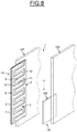
- FIGS. 5 to 9 illustrate measurement devices including the abovementioned detection device of FIG. 1 .
- FIGS. 1 to 3 illustrate a capacitive detection device 1 which comprises a capacitive detector 1 A and a containment electrode 1 B.
- the capacitive detector 1 A comprises a longitudinal ribbon 2 made of a dielectric material, flexible or rigid, a pair 3 of electrodes comprising a first electrode 4 and a second electrode 5 formed on a face 6 of the dielectric ribbon 2 and a third electrode 7 formed on the other face 8 of the dielectric ribbon 2 .
- the first electrode 4 is in the form of a comb and comprises parallel transverse branches 9 , evenly spaced apart and linked to one another by a longitudinal link branch 10 .
- the second electrode 5 is in the form of a comb and comprises parallel transverse branches 11 , evenly spaced apart and linked to one another by a longitudinal link branch 12 .
- the transverse branches 9 and 11 of the first and second electrodes 4 and 5 are arranged alternately between one another, have equal widths and equal lengths and are equidistantly spaced apart from one another, the transverse branches 9 extending toward the longitudinal link branch 12 and the parallel transverse branches 11 extending toward the longitudinal link branch 10 .
- Such an arrangement is called an interdigital structure.
- the transverse branches 9 and 11 are arranged according to a determined period ⁇ which comprises the addition of a width of the branches 9 of the electrode 4 of a width of the branches 11 of the electrode 5 and of two spaces 13 between two adjacent branches 9 and 11 .
- the third electrode 7 takes the form of a layer which, advantageously, covers an area of the face 8 of the dielectric ribbon 2 opposite the area of the face 6 of the dielectric ribbon 2 covered by the pair 3 of interdigital electrodes 4 and 5 .
- the dielectric ribbon 2 can be made of a plastic material such as a polyimide like Kapton, or such as a polytetrafluoroethylene (Teflon) and the electrodes 4 , 5 and 7 can be formed by layers of a metallic material such as copper or gold.
- the opposite faces of the capacitive detector 1 A can be covered with thin protective layers covering the pair 3 of interdigital electrodes 4 and 5 and the electrode 7 , these thin protective layers being for example made of a dielectric material.
- the containment electrode 1 B is formed by a plate made of an electrically conductive material, formed for example from a metal sheet of copper or of gold.
- the containment electrode 1 B is situated on the side or opposite the face 6 of the ribbon 2 bearing the pair 3 of interdigital electrodes 4 and 5 and is arranged parallel to and at a distance from the capacitive detector 1 A, such that there is a space of constant thickness between the capacitive detector 1 A and the containment electrode 1 B.
- the dielectric ribbon 2 can be, for example, made of a plastic material such as a polyimide like Kapton, or such as a polytetrafluoroethylene (Teflon).
- the thickness e of the dielectric ribbon 2 is less than or equal to said determined period ⁇ divided by four times PI, i.e. the formula (1): ⁇ /4 ⁇ e.
- the ratio resulting from the division in numerator of the capacitance C between two adjacent branches 9 and 11 of the first and second electrodes 4 and 5 in the presence of at least one chosen medium of dielectric permittivity ⁇ m , interposed between the capacitive detector 1 A and the containment electrode 1 B, and in denominator by the dielectric permittivity ( ⁇ m ) of the medium multiplied by the capacitance (Co) between the two adjacent branches 9 and 11 of the first and second electrodes 4 and 5 in the presence of vacuum is greater than or equal to one, i.e. the formula (2): C/ ⁇ m ⁇ Co ⁇ 1.
- the distance between the containment electrode 1 B and the capacitive detector 1 A can advantageously lie between a twentieth of and twenty times said determined period. ⁇ .
- the capacitive detection device 1 is linked to an electronic measurement circuit 14 .
- the first and second interdigital electrodes 4 and 5 are respectively linked to inputs 15 and 16 of the electronic measurement circuit 14 by electrical wires 15 a and 16 a .
- the third electrode 7 and the containment electrode 1 B are linked to a same input 17 of the electronic measurement circuit 14 by electrical wires 17 a and 17 b , such that the third electrode 7 and the containment electrode 1 B are linked to one another.
- the electronic measurement circuit 14 is adapted so that the third electrode 7 and the containment electrode 1 B, via the input 17 , are at a reference potential.
- the electronic measurement circuit 14 comprises a measurement device linked to the first and second interdigital electrodes 4 and 5 , via the inputs 15 and 16 , and capable of delivering on an output 18 an electrical signal relating to the measurement of the mutual capacitance between the first and second interdigital electrodes 4 and 5 . It is therefore the value of this electrical signal which constitutes the useful measured variable.
- the measurement device can thus be a so-called three-terminal device, and can involve a so-called Blumlein bridge measurement.
- the presence of the containment electrode 1 B influences the magnetic field lines in the environment of the pair 3 of interdigital electrodes 4 and 5 of the capacitive detector 1 A, by inducing a distribution of the field lines between the electrodes 4 and 5 of the capacitive electrode 1 A and also between the electrodes 4 and 5 and the containment electrode 1 B, such that the measurement of the mutual capacitance between the interdigital electrodes 4 and 5 depends on or varies as a function of the distance between the capacitive detector 1 A and the containment electrode 1 B, and/or on the relative overlap between the capacitive detector 1 A and the containment electrode 1 B and/or on the dielectric medium established between the capacitive detector 1 A and the containment electrode 1 B.
- the capacitive detection device 1 can be applied in many fields.
- the capacitive detection device 1 can be implemented to measure the level of a liquid in a tank or in a pipe.
- the capacitive detector 1 A and the containment electrode are placed substantially vertically, the branches 9 and 11 of the electrodes 4 and 5 being horizontal, such that a blade L of the liquid extends between them.
- the containment electrode 1 B covers, at a distance, all the surface of the capacitive detector 1 A.
- the dielectric medium established between the capacitive detector 1 A and the containment electrode 1 B is defined by a part of the liquid, in the form of a blade L of liquid, which covers a bottom portion of the pair 3 of interdigital electrodes 4 and 5 of the capacitive detector 1 A and of the containment electrode 1 B and, above the blade L with a gas.
- the dielectric permittivity ⁇ m of the chosen medium is that of the liquid.
- the number of horizontal branches 9 and 11 of the interdigital electrodes 4 and 5 , covered by the blade L of liquid, depends on the level of the free surface Ls of this blade L of liquid and therefore on the level of the free surface of the liquid in the tank or the pipe.
- the measured value of the mutual capacitance between the first and second interdigital electrodes 4 and 5 is a function of the length of the lower portion of the pair 3 of interdigital electrodes 4 and 5 of the capacitive detector 1 A, covered by the blade L of liquid and therefore, substantially on the number of horizontal branches 9 and 11 of the interdigital electrodes 4 and 5 , covered by the blade L of liquid.
- the electronic measurement circuit 14 is capable of delivering at its output 18 the situation and values of displacement of the level of the free surface Ls of the blade L of liquid and therefore the situation of the level of the liquid in the tank. Substantially, the variation of the measured value of the mutual capacitance between the first and second interdigital electrodes 4 and 5 is proportional to the length of the capacitive detector 1 A immersed in the liquid. By calculation, the electronic measurement circuit 14 can also be capable of delivering the rate of the displacements of the free surface Ls of the blade L of liquid.
- the containment electrode 1 B can be suspended in the tank by being held taught.
- the capacitive detector 1 A can be suspended in the tank or the pipe by being held taught.
- the capacitive detector 1 A can be attached to an internal wall of the tank or of the pipe.
- the capacitive detector 1 A can be attached to an outer wall of the tank or of the pipe provided that this wall is not metallic.
- the measurement device 1 can also be applied to the determination of the level of any materials in powder, particulate or grain form behaving in a way equivalent to a liquid.
- the capacitive detection device 1 can be implemented to measure the thickness of a film of a dielectric material, for example of a film of liquid extending between the capacitive detector 1 A and the containment electrode 1 B.
- the measured value of the mutual capacitance between the first and second interdigital electrodes 4 and 5 is a function of the thickness of the film.
- the electronic measurement circuit 14 is capable of delivering at its output 18 the value of the thickness of the film.
- the capacitive detection device 1 can be implemented to detect the presence of a mist, when the measured value of the mutual capacitance between the first and second interdigital electrodes 4 and 5 crosses a predetermined threshold, and/or the density of such a mist, the measured value of the mutual capacitance between the first and second interdigital electrodes 4 and 5 being a function of this density.
- the capacitive detector 1 A and the containment electrode 1 B are respectively secured to parts 101 and 102 that are mobile in the direction of convergence and/or of separation of the capacitive detector 1 A and the containment electrode 1 B, the dielectric medium between the capacitive detector 1 A and the containment electrode 1 B being deformable, for example a gas.
- the containment electrode 1 B covers, at a distance, all the surface of the capacitive detector 1 A.
- the dielectric permittivity ⁇ m of the chosen medium is that of the dielectric medium established between the capacitive detector 1 A and the containment electrode 1 B.
- the measured value of the mutual capacitance between the first and second interdigital electrodes 4 and 5 is a function of the distance between the capacitive detector 1 A and the containment electrode 1 B.
- the electronic measurement circuit 14 is capable of delivering at its output 18 the position and values of displacements of the parts 101 and 102 relative to one another.
- the electronic measurement circuit 14 can also be capable of delivering the rate of displacements of the parts 101 and 102 relative to one another.
- the capacitive detector 1 A and the containment electrode 1 B are secured to a part 103 .
- the containment electrode 1 B covers, at a distance, all the surface of the capacitive detector 1 A.
- a part 104 is provided with a dielectric blade 105 which is partially engaged between the capacitive detector 1 A and the containment electrode 1 B and which is arranged parallel to and at a distance from the latter.
- the parts are mobile relative to one another in the longitudinal direction of the capacitive detector 1 A.
- the dielectric blade 105 has a transverse end edge 106 parallel to the branches 8 and 9 of the interdigital electrodes 4 and 5 .
- the dielectric blade 105 covers, at a distance, all the surface of the capacitive detector 1 A.
- the measured value of the mutual capacitance between the first and second interdigital electrodes 4 and 5 is a function of the length of the portion of the pair 3 of interdigital electrodes 4 and 5 of the capacitive detector 1 A, covered by the dielectric blade 105 , and therefore, substantially on the number of horizontal branches 9 and 11 of the interdigital electrodes 4 and 5 , covered by the dielectric blade 105 .
- the electronic measurement circuit 14 is capable of delivering at its output 18 the longitudinal position of the dielectric blade 105 relative to the capacitive detector 1 A and therefore the longitudinal position and values of displacements of the parts 103 and 104 relative to one another. Substantially, the variation of the measured value of the mutual capacitance between the first and second interdigital electrodes 4 and 5 is proportional to the length of the dielectric blade 105 engaged between the capacitive detector 1 A and the containment electrode 1 B. By calculation, the electronic measurement circuit 14 can also be capable of delivering the rate of the displacements of the parts 103 and 104 relative to one another.
- the capacitive detector 1 A and the containment electrode 1 B are respectively secured to parts 107 and 108 that are longitudinally mobile relative to one another.
- the containment electrode 1 B has an end edge 109 parallel to the branches 9 and 11 of the interdigital electrodes 4 and 5 and is arranged so as to cover, at a distance, an end portion of the capacitive detector 1 A.
- the measured value of the mutual capacitance between the first and second interdigital electrodes 4 and 5 is a function of the length of the portion of the pair 3 of interdigital electrodes 4 and 5 of the capacitive detector 1 A covered, at a distance, by the containment electrode 1 B, and therefore of the longitudinal position of the parts 107 and 108 relative to one another.
- the electronic measurement circuit 14 is capable of delivering at its output 18 the longitudinal position of the containment electrode 1 B relative to the capacitive detector 1 A and therefore the longitudinal position and values of displacements of the parts 107 and 108 relative to one another. Substantially, the variation of the measured value of the mutual capacitance between the first and second interdigital electrodes 4 and 5 is proportional to the value of the overlap between the capacitive detector 1 A and the containment electrode 1 B. By calculation, the electronic measurement circuit 14 can also be capable of delivering the rate of the displacements of the parts 107 and 108 relative to one another.
- the parts 110 and 111 are rotationally mobile relative to one another according to an axis of rotation.
- the capacitive detector 1 A and the containment electrode 1 B are respectively secured to the parts 110 and 111 and are formed in an annular fashion according to circumferences co-axial to parts 110 and 111 , the capacitive detector 1 A and the containment electrode 1 B radially facing one another.
- the branches 9 and 11 of the interdigital electrodes extend axially.
- the containment electrode 1 B has an axial end edge 112 parallel to the branches 9 and 11 of the interdigital electrodes 4 and 5 and is arranged so as to cover, at a distance, an end portion of the capacitive detector 1 A.
- the capacitive detector 1 A and the containment electrode 1 B could be arranged axially facing one another, the branches 9 and 11 of the interdigital electrodes then extending radially and the edge 112 then extending radially.
- the measured value of the mutual capacitance between the first and second interdigital electrodes 4 and 5 is a function of the length of the arc of the portion of the pair 3 of interdigital electrodes 4 and 5 of the capacitive detector 1 A, covered, at a distance, by the arc of the containment electrode 1 B, and therefore of the annular position of the parts 107 and 108 relative to one another.
- the electronic measurement circuit 14 is capable of delivering at its output 18 the angular position of the containment electrode 1 B relative to the capacitive detector 1 A and therefore the angular position and values of angular displacements of the parts 107 and 108 relative to one another.
- the electronic measurement circuit 14 can also be capable of delivering the rate of rotation of the parts 107 and 108 relative to one another.
- the containment electrode 1 B can be fixed to the part which bears it via a sheet 113 of a dielectric material, for example of a plastic material such as a polyimide like Kapton, or such as a polytetrafluoroethylene (Teflon), in order to avoid having the material of the part which bears the containment electrode 1 B prevent or influence the measurements performed.
- the containment electrode 1 B can consist of a metal part of the part, subject to the condition, notably in the applications of FIGS.
Landscapes
- Physics & Mathematics (AREA)
- General Physics & Mathematics (AREA)
- Engineering & Computer Science (AREA)
- Power Engineering (AREA)
- Electromagnetism (AREA)
- Thermal Sciences (AREA)
- Fluid Mechanics (AREA)
- Measurement Of Length, Angles, Or The Like Using Electric Or Magnetic Means (AREA)
- Measurement Of Levels Of Liquids Or Fluent Solid Materials (AREA)
- Transmission And Conversion Of Sensor Element Output (AREA)
Applications Claiming Priority (2)
| Application Number | Priority Date | Filing Date | Title |
|---|---|---|---|
| FR1654349 | 2016-05-17 | ||
| FR1654349A FR3051553B1 (fr) | 2016-05-17 | 2016-05-17 | Dispositif de detection capacitive et dispositif de mesure l'incluant |
Publications (2)
| Publication Number | Publication Date |
|---|---|
| US20170336242A1 US20170336242A1 (en) | 2017-11-23 |
| US10697818B2 true US10697818B2 (en) | 2020-06-30 |
Family
ID=57113444
Family Applications (1)
| Application Number | Title | Priority Date | Filing Date |
|---|---|---|---|
| US15/597,017 Active 2037-10-25 US10697818B2 (en) | 2016-05-17 | 2017-05-16 | Capacitive detection device and measuring device including same |
Country Status (3)
| Country | Link |
|---|---|
| US (1) | US10697818B2 (fr) |
| EP (1) | EP3246667B1 (fr) |
| FR (1) | FR3051553B1 (fr) |
Cited By (1)
| Publication number | Priority date | Publication date | Assignee | Title |
|---|---|---|---|---|
| US20220026256A1 (en) * | 2018-12-13 | 2022-01-27 | Charles Austen Pumps Ltd. | Capacitive liquid level sensor and liquid sensor assembly |
Families Citing this family (6)
| Publication number | Priority date | Publication date | Assignee | Title |
|---|---|---|---|---|
| FR3076901B1 (fr) | 2018-01-12 | 2020-02-07 | Kapflex | Dispositif de mesures capacitives dans un milieu multiphasique |
| KR102135683B1 (ko) * | 2018-07-09 | 2020-07-20 | 최기환 | 누액 감지 센서 및 누액 감지 장치 |
| US11133799B2 (en) * | 2019-11-20 | 2021-09-28 | Ford Global Technologies, Llc | Capacitive proximity sensor assembly having multiple sensing configurations |
| CN112857520B (zh) * | 2019-11-28 | 2024-11-01 | 广东美的厨房电器制造有限公司 | 一种水位检测方法及装置 |
| CN115683275A (zh) * | 2022-11-02 | 2023-02-03 | 河源市嘉辰科技有限公司 | 交扣叉指电极结构、电容式水位传感器及精密水位检测装置 |
| CN119147072B (zh) * | 2024-11-11 | 2025-03-04 | 四川泛华航空仪表电器有限公司 | 一种航空油箱用非接触式油位测量装置及测量方法 |
Citations (6)
| Publication number | Priority date | Publication date | Assignee | Title |
|---|---|---|---|---|
| EP0508143A2 (fr) | 1991-04-08 | 1992-10-14 | Berthold Koch | Dispositif de mesure du niveau d'un fluide |
| WO2008101333A1 (fr) | 2007-02-23 | 2008-08-28 | Warren Michael Levy | Dispositif de détection d'un niveau de fluide et ses procédés d'utilisation |
| WO2009122061A2 (fr) | 2008-04-04 | 2009-10-08 | Universite Joseph Fourier | Detecteur capacitif, procede de fabrication d'un detecteur capacitif et dispositif de mesure l'integrant |
| WO2010023766A1 (fr) | 2008-09-01 | 2010-03-04 | パイオニア株式会社 | Capteur de déplacement |
| US20110120219A1 (en) * | 2004-12-22 | 2011-05-26 | Inergy Auto. Systems Research (Societe Anonyme) | Capacitive liquid level sensor |
| US20120111107A1 (en) | 2009-07-10 | 2012-05-10 | Sony Corporation | Liquid tank and fuel cell |
-
2016
- 2016-05-17 FR FR1654349A patent/FR3051553B1/fr not_active Expired - Fee Related
-
2017
- 2017-05-15 EP EP17171076.7A patent/EP3246667B1/fr active Active
- 2017-05-16 US US15/597,017 patent/US10697818B2/en active Active
Patent Citations (8)
| Publication number | Priority date | Publication date | Assignee | Title |
|---|---|---|---|---|
| EP0508143A2 (fr) | 1991-04-08 | 1992-10-14 | Berthold Koch | Dispositif de mesure du niveau d'un fluide |
| US5207098A (en) | 1991-04-08 | 1993-05-04 | Berthold Koch | Device to measure the level of material within a container |
| US20110120219A1 (en) * | 2004-12-22 | 2011-05-26 | Inergy Auto. Systems Research (Societe Anonyme) | Capacitive liquid level sensor |
| WO2008101333A1 (fr) | 2007-02-23 | 2008-08-28 | Warren Michael Levy | Dispositif de détection d'un niveau de fluide et ses procédés d'utilisation |
| WO2009122061A2 (fr) | 2008-04-04 | 2009-10-08 | Universite Joseph Fourier | Detecteur capacitif, procede de fabrication d'un detecteur capacitif et dispositif de mesure l'integrant |
| US20110107833A1 (en) * | 2008-04-04 | 2011-05-12 | Pierre Thibault | Capacitive detector, method for manufacturing same, and device for measuring the integral |
| WO2010023766A1 (fr) | 2008-09-01 | 2010-03-04 | パイオニア株式会社 | Capteur de déplacement |
| US20120111107A1 (en) | 2009-07-10 | 2012-05-10 | Sony Corporation | Liquid tank and fuel cell |
Non-Patent Citations (1)
| Title |
|---|
| Search Report and Written Opinion, dated Feb. 10, 2017, in priority French Patent Application No. 1654349, dated May 17, 2016, 6 pages. |
Cited By (2)
| Publication number | Priority date | Publication date | Assignee | Title |
|---|---|---|---|---|
| US20220026256A1 (en) * | 2018-12-13 | 2022-01-27 | Charles Austen Pumps Ltd. | Capacitive liquid level sensor and liquid sensor assembly |
| US11976958B2 (en) * | 2018-12-13 | 2024-05-07 | Charles Austen Pumps Ltd. | Capacitive liquid level sensor and liquid sensor assembly |
Also Published As
| Publication number | Publication date |
|---|---|
| US20170336242A1 (en) | 2017-11-23 |
| FR3051553B1 (fr) | 2018-06-15 |
| EP3246667A1 (fr) | 2017-11-22 |
| EP3246667B1 (fr) | 2018-12-26 |
| FR3051553A1 (fr) | 2017-11-24 |
Similar Documents
| Publication | Publication Date | Title |
|---|---|---|
| US10697818B2 (en) | Capacitive detection device and measuring device including same | |
| US8393209B2 (en) | Capacitive detector, method for manufacturing same, and device for measuring the integral | |
| US11022473B2 (en) | Calibration-free continuous bin level sensor | |
| Huang et al. | Optimization of the coplanar interdigital capacitive sensor | |
| EP3487628B1 (fr) | Capteur de niveau capacitif de fluide continu | |
| US6318172B1 (en) | Capacitive level detector with optimized electrode geometry | |
| EP2203738B1 (fr) | Structure améliorée pour l'équilibrage capacitif d'un capteur d'humidité relative intégré et procédé de fabrication | |
| CN102736804A (zh) | 单层感应层的二维电容式触控板 | |
| US9880119B2 (en) | Apparatus for identifying a value of a property of a fluid which is to be measured, method for operating an apparatus for identifying a value of a property of a fluid which is to be measured, and method for manufacturing an apparatus for identifying a value of a property of a fluid which is to be measured | |
| KR102744686B1 (ko) | 고유전상수 유체에 직접적으로 삽입하기 위한 유전-상수-비민감성 유체 레벨 센서 | |
| Saleh et al. | Capacitive sensing for measuring oil thickness under fouling conditions | |
| CN100412534C (zh) | 一种微型电容层析成像传感器 | |
| JP3197515U (ja) | 液面レベルセンサ | |
| JP6132482B2 (ja) | 液位検出装置 | |
| TW201314184A (zh) | 比例式多重切換物液位量測方法及裝置 | |
| JP6294600B2 (ja) | 静電容量式レベルセンサ | |
| US9939418B2 (en) | System and method for multiphase flow measurements | |
| US10732065B2 (en) | Apparatus and method of detecting breaches in pipelines | |
| CN106352783B (zh) | 厚度检测装置 | |
| Nikolov et al. | The effect of a pattern of capacitive sensors for liquid level measurements | |
| Maurya et al. | Interdigital Multi-sensor Structures for Resistance and Capacitance Sensing | |
| Bonilla Riaño et al. | High spatial and temporal resolution film thickness planar sensor: comparison of geometries | |
| Jamshir et al. | ML Enabled Parallel RC Sensor for Level and Electrical Conductivity Measurement | |
| US12510503B2 (en) | Sensor device and method for determination of properties of a liquid | |
| RU2337327C2 (ru) | Устройство измерения уровней границ раздела сред и способ измерения уровней границ раздела сред |
Legal Events
| Date | Code | Title | Description |
|---|---|---|---|
| AS | Assignment |
Owner name: UNIVERSITE GRENOBLE ALPES, FRANCE Free format text: ASSIGNMENT OF ASSIGNORS INTEREST;ASSIGNOR:THIBAULT, PIERRE JEAN-YVES;REEL/FRAME:043338/0478 Effective date: 20170615 |
|
| STPP | Information on status: patent application and granting procedure in general |
Free format text: DOCKETED NEW CASE - READY FOR EXAMINATION |
|
| STPP | Information on status: patent application and granting procedure in general |
Free format text: NON FINAL ACTION MAILED |
|
| STPP | Information on status: patent application and granting procedure in general |
Free format text: RESPONSE TO NON-FINAL OFFICE ACTION ENTERED AND FORWARDED TO EXAMINER |
|
| STPP | Information on status: patent application and granting procedure in general |
Free format text: NOTICE OF ALLOWANCE MAILED -- APPLICATION RECEIVED IN OFFICE OF PUBLICATIONS |
|
| STPP | Information on status: patent application and granting procedure in general |
Free format text: DOCKETED NEW CASE - READY FOR EXAMINATION |
|
| STPP | Information on status: patent application and granting procedure in general |
Free format text: NOTICE OF ALLOWANCE MAILED -- APPLICATION RECEIVED IN OFFICE OF PUBLICATIONS |
|
| STCF | Information on status: patent grant |
Free format text: PATENTED CASE |
|
| MAFP | Maintenance fee payment |
Free format text: PAYMENT OF MAINTENANCE FEE, 4TH YR, SMALL ENTITY (ORIGINAL EVENT CODE: M2551); ENTITY STATUS OF PATENT OWNER: SMALL ENTITY Year of fee payment: 4 |