US10746802B2 - System and method for preventing abnormal opening of contactor through real-time operation detection - Google Patents
System and method for preventing abnormal opening of contactor through real-time operation detection Download PDFInfo
- Publication number
- US10746802B2 US10746802B2 US16/066,239 US201716066239A US10746802B2 US 10746802 B2 US10746802 B2 US 10746802B2 US 201716066239 A US201716066239 A US 201716066239A US 10746802 B2 US10746802 B2 US 10746802B2
- Authority
- US
- United States
- Prior art keywords
- control unit
- contactor coil
- contactor
- main control
- signal
- Prior art date
- Legal status (The legal status is an assumption and is not a legal conclusion. Google has not performed a legal analysis and makes no representation as to the accuracy of the status listed.)
- Active, expires
Links
Images



Classifications
-
- B—PERFORMING OPERATIONS; TRANSPORTING
- B60—VEHICLES IN GENERAL
- B60L—PROPULSION OF ELECTRICALLY-PROPELLED VEHICLES; SUPPLYING ELECTRIC POWER FOR AUXILIARY EQUIPMENT OF ELECTRICALLY-PROPELLED VEHICLES; ELECTRODYNAMIC BRAKE SYSTEMS FOR VEHICLES IN GENERAL; MAGNETIC SUSPENSION OR LEVITATION FOR VEHICLES; MONITORING OPERATING VARIABLES OF ELECTRICALLY-PROPELLED VEHICLES; ELECTRIC SAFETY DEVICES FOR ELECTRICALLY-PROPELLED VEHICLES
- B60L3/00—Electric devices on electrically-propelled vehicles for safety purposes; Monitoring operating variables, e.g. speed, deceleration or energy consumption
- B60L3/0023—Detecting, eliminating, remedying or compensating for drive train abnormalities, e.g. failures within the drive train
- B60L3/0084—Detecting, eliminating, remedying or compensating for drive train abnormalities, e.g. failures within the drive train relating to control modules
-
- B—PERFORMING OPERATIONS; TRANSPORTING
- B60—VEHICLES IN GENERAL
- B60L—PROPULSION OF ELECTRICALLY-PROPELLED VEHICLES; SUPPLYING ELECTRIC POWER FOR AUXILIARY EQUIPMENT OF ELECTRICALLY-PROPELLED VEHICLES; ELECTRODYNAMIC BRAKE SYSTEMS FOR VEHICLES IN GENERAL; MAGNETIC SUSPENSION OR LEVITATION FOR VEHICLES; MONITORING OPERATING VARIABLES OF ELECTRICALLY-PROPELLED VEHICLES; ELECTRIC SAFETY DEVICES FOR ELECTRICALLY-PROPELLED VEHICLES
- B60L3/00—Electric devices on electrically-propelled vehicles for safety purposes; Monitoring operating variables, e.g. speed, deceleration or energy consumption
-
- B—PERFORMING OPERATIONS; TRANSPORTING
- B60—VEHICLES IN GENERAL
- B60L—PROPULSION OF ELECTRICALLY-PROPELLED VEHICLES; SUPPLYING ELECTRIC POWER FOR AUXILIARY EQUIPMENT OF ELECTRICALLY-PROPELLED VEHICLES; ELECTRODYNAMIC BRAKE SYSTEMS FOR VEHICLES IN GENERAL; MAGNETIC SUSPENSION OR LEVITATION FOR VEHICLES; MONITORING OPERATING VARIABLES OF ELECTRICALLY-PROPELLED VEHICLES; ELECTRIC SAFETY DEVICES FOR ELECTRICALLY-PROPELLED VEHICLES
- B60L3/00—Electric devices on electrically-propelled vehicles for safety purposes; Monitoring operating variables, e.g. speed, deceleration or energy consumption
- B60L3/04—Cutting off the power supply under fault conditions
-
- B—PERFORMING OPERATIONS; TRANSPORTING
- B60—VEHICLES IN GENERAL
- B60L—PROPULSION OF ELECTRICALLY-PROPELLED VEHICLES; SUPPLYING ELECTRIC POWER FOR AUXILIARY EQUIPMENT OF ELECTRICALLY-PROPELLED VEHICLES; ELECTRODYNAMIC BRAKE SYSTEMS FOR VEHICLES IN GENERAL; MAGNETIC SUSPENSION OR LEVITATION FOR VEHICLES; MONITORING OPERATING VARIABLES OF ELECTRICALLY-PROPELLED VEHICLES; ELECTRIC SAFETY DEVICES FOR ELECTRICALLY-PROPELLED VEHICLES
- B60L50/00—Electric propulsion with power supplied within the vehicle
- B60L50/50—Electric propulsion with power supplied within the vehicle using propulsion power supplied by batteries or fuel cells
- B60L50/60—Electric propulsion with power supplied within the vehicle using propulsion power supplied by batteries or fuel cells using power supplied by batteries
-
- B—PERFORMING OPERATIONS; TRANSPORTING
- B60—VEHICLES IN GENERAL
- B60L—PROPULSION OF ELECTRICALLY-PROPELLED VEHICLES; SUPPLYING ELECTRIC POWER FOR AUXILIARY EQUIPMENT OF ELECTRICALLY-PROPELLED VEHICLES; ELECTRODYNAMIC BRAKE SYSTEMS FOR VEHICLES IN GENERAL; MAGNETIC SUSPENSION OR LEVITATION FOR VEHICLES; MONITORING OPERATING VARIABLES OF ELECTRICALLY-PROPELLED VEHICLES; ELECTRIC SAFETY DEVICES FOR ELECTRICALLY-PROPELLED VEHICLES
- B60L53/00—Methods of charging batteries, specially adapted for electric vehicles; Charging stations or on-board charging equipment therefor; Exchange of energy storage elements in electric vehicles
- B60L53/10—Methods of charging batteries, specially adapted for electric vehicles; Charging stations or on-board charging equipment therefor; Exchange of energy storage elements in electric vehicles characterised by the energy transfer between the charging station and the vehicle
- B60L53/14—Conductive energy transfer
-
- B—PERFORMING OPERATIONS; TRANSPORTING
- B60—VEHICLES IN GENERAL
- B60R—VEHICLES, VEHICLE FITTINGS, OR VEHICLE PARTS, NOT OTHERWISE PROVIDED FOR
- B60R16/00—Electric or fluid circuits specially adapted for vehicles and not otherwise provided for; Arrangement of elements of electric or fluid circuits specially adapted for vehicles and not otherwise provided for
- B60R16/02—Electric or fluid circuits specially adapted for vehicles and not otherwise provided for; Arrangement of elements of electric or fluid circuits specially adapted for vehicles and not otherwise provided for electric constitutive elements
- B60R16/023—Electric or fluid circuits specially adapted for vehicles and not otherwise provided for; Arrangement of elements of electric or fluid circuits specially adapted for vehicles and not otherwise provided for electric constitutive elements for transmission of signals between vehicle parts or subsystems
- B60R16/0231—Circuits relating to the driving or the functioning of the vehicle
- B60R16/0232—Circuits relating to the driving or the functioning of the vehicle for measuring vehicle parameters and indicating critical, abnormal or dangerous conditions
-
- G—PHYSICS
- G01—MEASURING; TESTING
- G01R—MEASURING ELECTRIC VARIABLES; MEASURING MAGNETIC VARIABLES
- G01R31/00—Arrangements for testing electric properties; Arrangements for locating electric faults; Arrangements for electrical testing characterised by what is being tested not provided for elsewhere
-
- G—PHYSICS
- G01—MEASURING; TESTING
- G01R—MEASURING ELECTRIC VARIABLES; MEASURING MAGNETIC VARIABLES
- G01R31/00—Arrangements for testing electric properties; Arrangements for locating electric faults; Arrangements for electrical testing characterised by what is being tested not provided for elsewhere
- G01R31/005—Testing of electric installations on transport means
- G01R31/006—Testing of electric installations on transport means on road vehicles, e.g. automobiles or trucks
-
- G—PHYSICS
- G01—MEASURING; TESTING
- G01R—MEASURING ELECTRIC VARIABLES; MEASURING MAGNETIC VARIABLES
- G01R31/00—Arrangements for testing electric properties; Arrangements for locating electric faults; Arrangements for electrical testing characterised by what is being tested not provided for elsewhere
- G01R31/327—Testing of circuit interrupters, switches or circuit-breakers
-
- G—PHYSICS
- G01—MEASURING; TESTING
- G01R—MEASURING ELECTRIC VARIABLES; MEASURING MAGNETIC VARIABLES
- G01R31/00—Arrangements for testing electric properties; Arrangements for locating electric faults; Arrangements for electrical testing characterised by what is being tested not provided for elsewhere
- G01R31/327—Testing of circuit interrupters, switches or circuit-breakers
- G01R31/3277—Testing of circuit interrupters, switches or circuit-breakers of low voltage devices, e.g. domestic or industrial devices, such as motor protections, relays, rotation switches
- G01R31/3278—Testing of circuit interrupters, switches or circuit-breakers of low voltage devices, e.g. domestic or industrial devices, such as motor protections, relays, rotation switches of relays, solenoids or reed switches
-
- G—PHYSICS
- G01—MEASURING; TESTING
- G01R—MEASURING ELECTRIC VARIABLES; MEASURING MAGNETIC VARIABLES
- G01R31/00—Arrangements for testing electric properties; Arrangements for locating electric faults; Arrangements for electrical testing characterised by what is being tested not provided for elsewhere
- G01R31/36—Arrangements for testing, measuring or monitoring the electrical condition of accumulators or electric batteries, e.g. capacity or state of charge [SoC]
-
- G—PHYSICS
- G01—MEASURING; TESTING
- G01R—MEASURING ELECTRIC VARIABLES; MEASURING MAGNETIC VARIABLES
- G01R31/00—Arrangements for testing electric properties; Arrangements for locating electric faults; Arrangements for electrical testing characterised by what is being tested not provided for elsewhere
- G01R31/36—Arrangements for testing, measuring or monitoring the electrical condition of accumulators or electric batteries, e.g. capacity or state of charge [SoC]
- G01R31/382—Arrangements for monitoring battery or accumulator variables, e.g. SoC
- G01R31/3842—Arrangements for monitoring battery or accumulator variables, e.g. SoC combining voltage and current measurements
-
- H—ELECTRICITY
- H01—ELECTRIC ELEMENTS
- H01H—ELECTRIC SWITCHES; RELAYS; SELECTORS; EMERGENCY PROTECTIVE DEVICES
- H01H47/00—Circuit arrangements not adapted to a particular application of the relay and designed to obtain desired operating characteristics or to provide energising current
- H01H47/002—Monitoring or fail-safe circuits
-
- B—PERFORMING OPERATIONS; TRANSPORTING
- B60—VEHICLES IN GENERAL
- B60L—PROPULSION OF ELECTRICALLY-PROPELLED VEHICLES; SUPPLYING ELECTRIC POWER FOR AUXILIARY EQUIPMENT OF ELECTRICALLY-PROPELLED VEHICLES; ELECTRODYNAMIC BRAKE SYSTEMS FOR VEHICLES IN GENERAL; MAGNETIC SUSPENSION OR LEVITATION FOR VEHICLES; MONITORING OPERATING VARIABLES OF ELECTRICALLY-PROPELLED VEHICLES; ELECTRIC SAFETY DEVICES FOR ELECTRICALLY-PROPELLED VEHICLES
- B60L2240/00—Control parameters of input or output; Target parameters
- B60L2240/40—Drive Train control parameters
- B60L2240/54—Drive Train control parameters related to batteries
- B60L2240/547—Voltage
-
- B—PERFORMING OPERATIONS; TRANSPORTING
- B60—VEHICLES IN GENERAL
- B60L—PROPULSION OF ELECTRICALLY-PROPELLED VEHICLES; SUPPLYING ELECTRIC POWER FOR AUXILIARY EQUIPMENT OF ELECTRICALLY-PROPELLED VEHICLES; ELECTRODYNAMIC BRAKE SYSTEMS FOR VEHICLES IN GENERAL; MAGNETIC SUSPENSION OR LEVITATION FOR VEHICLES; MONITORING OPERATING VARIABLES OF ELECTRICALLY-PROPELLED VEHICLES; ELECTRIC SAFETY DEVICES FOR ELECTRICALLY-PROPELLED VEHICLES
- B60L2250/00—Driver interactions
- B60L2250/10—Driver interactions by alarm
-
- B—PERFORMING OPERATIONS; TRANSPORTING
- B60—VEHICLES IN GENERAL
- B60Y—INDEXING SCHEME RELATING TO ASPECTS CROSS-CUTTING VEHICLE TECHNOLOGY
- B60Y2200/00—Type of vehicle
- B60Y2200/90—Vehicles comprising electric prime movers
- B60Y2200/91—Electric vehicles
-
- Y—GENERAL TAGGING OF NEW TECHNOLOGICAL DEVELOPMENTS; GENERAL TAGGING OF CROSS-SECTIONAL TECHNOLOGIES SPANNING OVER SEVERAL SECTIONS OF THE IPC; TECHNICAL SUBJECTS COVERED BY FORMER USPC CROSS-REFERENCE ART COLLECTIONS [XRACs] AND DIGESTS
- Y02—TECHNOLOGIES OR APPLICATIONS FOR MITIGATION OR ADAPTATION AGAINST CLIMATE CHANGE
- Y02T—CLIMATE CHANGE MITIGATION TECHNOLOGIES RELATED TO TRANSPORTATION
- Y02T10/00—Road transport of goods or passengers
- Y02T10/60—Other road transportation technologies with climate change mitigation effect
- Y02T10/70—Energy storage systems for electromobility, e.g. batteries
-
- Y—GENERAL TAGGING OF NEW TECHNOLOGICAL DEVELOPMENTS; GENERAL TAGGING OF CROSS-SECTIONAL TECHNOLOGIES SPANNING OVER SEVERAL SECTIONS OF THE IPC; TECHNICAL SUBJECTS COVERED BY FORMER USPC CROSS-REFERENCE ART COLLECTIONS [XRACs] AND DIGESTS
- Y02—TECHNOLOGIES OR APPLICATIONS FOR MITIGATION OR ADAPTATION AGAINST CLIMATE CHANGE
- Y02T—CLIMATE CHANGE MITIGATION TECHNOLOGIES RELATED TO TRANSPORTATION
- Y02T10/00—Road transport of goods or passengers
- Y02T10/60—Other road transportation technologies with climate change mitigation effect
- Y02T10/7072—Electromobility specific charging systems or methods for batteries, ultracapacitors, supercapacitors or double-layer capacitors
-
- Y—GENERAL TAGGING OF NEW TECHNOLOGICAL DEVELOPMENTS; GENERAL TAGGING OF CROSS-SECTIONAL TECHNOLOGIES SPANNING OVER SEVERAL SECTIONS OF THE IPC; TECHNICAL SUBJECTS COVERED BY FORMER USPC CROSS-REFERENCE ART COLLECTIONS [XRACs] AND DIGESTS
- Y02—TECHNOLOGIES OR APPLICATIONS FOR MITIGATION OR ADAPTATION AGAINST CLIMATE CHANGE
- Y02T—CLIMATE CHANGE MITIGATION TECHNOLOGIES RELATED TO TRANSPORTATION
- Y02T90/00—Enabling technologies or technologies with a potential or indirect contribution to GHG emissions mitigation
- Y02T90/10—Technologies relating to charging of electric vehicles
- Y02T90/14—Plug-in electric vehicles
Definitions
- the present invention relates to a system and a method of preventing a contactor from being abnormally opened through a real-time operation detection, and more particularly, to a system and a method of preventing a contactor from being abnormally opened through a real-time operation detection, in which when a contactor coil control unit, which applies an operation signal to a contactor coil (relay coil) that opens or connects contact points of a contactor (relay), during a travelling of a vehicle applies an abnormal signal to the contactor coil due to an external reason or failure, the abnormal signal is detected in real time, so that it is possible to prevent the contact point of the contactor from being unintentionally opened by the abnormal signal, and particularly, it is possible to prevent an operating vehicle from being suddenly stopped by determining whether the vehicle actually travels based on a maintenance time of the abnormal signal and whether the abnormal signal is applied due to an actual failure of the contactor coil control unit.
- a contactor coil control unit which applies an operation signal to a contactor coil (relay coil) that opens or connect
- a plug-in hybrid electric vehicle which travels by using energy output from a battery as a power source, requires a charge of an internal battery according to driving of a motor of a vehicle, and in this case, a switching element called a contactor (or relay) is used in order to electrically conduct or block a current flowing between a charging source and the battery.
- a contactor or relay
- the contactor may be generally implemented with contact points and a contactor coil, and when power is supplied to the contactor coil and electromagnetic force is generated, the contact points are in contact with one another and a current may be conducted, and in this case, the supply of power to the contactor coil is generally available through a contactor coil control unit.
- the contactor coil control unit may allow electromagnetic force to be generated in the contactor coil by supplying power to the contactor coil, and in contrast to this, the contactor coil control unit may also collect the electromagnetic force of the contactor coil by blocking the supply of power.
- the contactor coil control unit applies an operation signal which unintentionally stops an operation of the contactor coil due to a sudden failure to the contactor coil, the operation of the contactor coil may be unintentionally stopped, and thus, there is a concern that the current conduction in the circuit is blocked while the contact points of the contactor are opened.
- contactor detecting technologies and methods of diagnosing an abnormal operation of a contactor and handling the abnormal operation have been developed in the related art, but when the contactor coil control unit applies an abnormal signal, the related arts cannot accurately determine whether the corresponding abnormal signal is a signal generated by an external impact of a vehicle or a signal generated by an actual failure of the contactor coil control unit, and particularly, the related arts have limitations in that there is no technology for maintaining a connection state of a contact point of a contactor for a predetermined time in a situation where an abnormal signal is applied from the contactor coil control unit, so that there is a concern that the contact point of the contactor is opened during an operation situation of a vehicle, or forcibly opening the contact point of the contactor in a situation where an operation of the vehicle is impossible.
- the present inventor develops a system and a method of preventing a contactor from being abnormally opened through a real-time operation detection, in which when a contactor coil control unit, which applies an operation signal to a contactor coil (relay coil) that opens or connects contact points of a contactor (relay), during a travelling of a vehicle applies an abnormal signal to the contactor coil by an external reason or a failure, the abnormal signal is detected in real time, so that it is possible to prevent the contact point of the contactor from being unintentionally opened by the abnormal signal, and particularly, it is possible to prevent an operating vehicle from being suddenly stopped by determining whether the vehicle actually travels based on a maintenance time of the abnormal signal and whether the abnormal signal is applied due to an actual failure of the contactor coil control unit.
- the present invention is conceived to solve the aforementioned problem, and an object of the present invention is to provide a system and a method of preventing a contactor from being abnormally opened through a real-time operation detection, in which when a contactor coil control unit, which applies an operation signal to a contactor coil (relay coil) that opens or connects contact points of a contactor (relay), during a travelling of a vehicle applies an abnormal signal to the contactor coil by an external reason or a failure, the abnormal signal is detected in real time, so that it is possible to prevent the contact point of the contactor from being unintentionally opened by the abnormal signal, and particularly, it is possible to prevent an operating vehicle from being suddenly stopped by determining whether the vehicle actually travels based on a maintenance time of the abnormal signal and whether the abnormal signal is applied due to an actual failure of the contactor coil control unit.
- a system for preventing a contactor from being abnormally opened through a real-time operation detection includes: a contactor coil provided in a contactor that connects a battery and an inverter; a contactor coil control unit which applies an operation signal to the contactor coil; and a main control unit which detects the operation signal applied from the contactor coil control unit in real time through an execution of a first detection mode, and executes a second detection mode and directly controls an operation state of the contactor coil based on a maintenance time of an abnormal signal when it is determined that the applied operation signal is the non-predetermined abnormal signal.
- the first detection mode may be a normal mode executed when the contactor coil control unit applies the operation signal
- the second detection mode may be a maintenance mode executed for preventing a contact point of the contactor from being opened according to the application of the abnormal signal from the contactor coil control unit.
- the main control unit may set a counting time for maintaining a contact point of the contactor in a close state for a predetermined time during the execution of the second detection mode.
- the main control unit may determine whether the contactor coil control unit applies a predetermined operation signal, and when it is determined that the contactor coil control unit applies the predetermined operation signal, the main control unit may execute the first detection mode.
- the main control unit may forcibly open the contact point of the contactor.
- the main control unit may generate an alarm signal according to the forcible open of the contact point of the contactor.
- the main control unit may determine whether the vehicle is operated in real time based on an output voltage of the battery during the execution of the second detection mode, and when it is determined that the vehicle is currently operated as a result of the determination, the main control unit may set the counting time.
- the main control unit may determine whether the abnormal signal is a signal generated by an external impact of the vehicle or a signal generated by a failure of the contactor coil control unit based on the maintenance time of the abnormal signal during the execution of the second detection mode, and when it is determined that the contactor coil control unit incurs failure, the main control unit may generate an alarm signal for the failure of the contactor coil control unit.
- the main control unit may include first and second main control units which are connected to terminals of both poles of the contactor coil, respectively, and the main control unit may directly control an operation state of the contactor coil according to the maintenance time of the abnormal signal through the first and second main control units.
- the present invention may further include: a voltage determining unit which measures a voltage of the battery and a voltage of the inverter according to the operation signal applied from the contactor coil control unit; and a current determining unit which measures a current flowing between the battery and the inverter according to the operation signal applied from the contactor coil control unit, in which the main control unit may determine that the applied operation signal is a non-predetermined abnormal signal according to the measured current and a voltage difference between the battery and the inverter.
- a method of preventing a contactor from being abnormally opened through a real-time operation detection includes: applying, by a contactor coil control unit, an operation signal to a contactor coil provided in a contactor that connects a battery and an inverter; and detecting, by a main control unit, the operation signal applied from the contactor coil control unit in real time through an execution of a first detection mode, and executing a second detection mode and directly controlling an operation state of the contactor coil based on a maintenance time of an abnormal signal when it is determined that the applied operation signal is the non-predetermined abnormal signal.
- the first detection mode in the directly controlling of the operation state of the contactor coil, may be a normal mode executed when the contactor coil control unit applies the operation signal, and the second detection mode may be a maintenance mode executed for preventing a contact point of the contactor from being opened according to the application of the abnormal signal from the contactor coil control unit.
- the directly controlling of the operation state of the contactor coil may include setting a counting time for maintaining a contact point of the contactor in a close state for a predetermined time during the execution of the second detection mode.
- the directly controlling of the operation state of the contactor coil may include, when the maintenance time of the abnormal signal is less than the counting time during the execution of the second detection mode, determining, by the main control unit, whether the contactor coil control unit applies a predetermined operation signal, and when it is determined that the contactor coil control unit applies the predetermined operation signal, executing, by the main control unit, the first detection mode.
- the directly controlling of the operation state of the contactor coil may include, when the maintenance time of the abnormal signal exceeds the counting time during the execution of the second detection mode, forcibly opening, by the main control unit, the contact point of the contactor.
- the directly controlling of the operation state of the contactor coil may further include generating an alarm signal according to the forcible open of the contact point of the contactor.
- the directly controlling of the operation state of the contactor coil may further include determining, by the main control unit, whether the vehicle is operated in real time based on an output voltage of the battery during the execution of the second detection mode, and when it is determined that the vehicle is currently operated as a result of the determination, setting the counting time.
- the directly controlling of the operation state of the contactor coil may include determining, by the main control unit, whether the abnormal signal is a signal generated by an external impact of the vehicle or a signal generated by a failure of the contactor coil control unit based on the maintenance time of the abnormal signal during the execution of the second detection mode, and when it is determined that the contactor coil control unit incurs failure, generating an alarm signal for the failure of the contactor coil control unit.
- the directly controlling of the operation state of the contactor coil may include directly controlling an operation state of the contactor coil according to the maintenance time of the abnormal signal through first and second main control units, which are included in the main control unit and are connected to terminals of both poles of the contactor coil, respectively.
- the present invention may further include: measuring, by a voltage determining unit, a voltage of the battery and a voltage of the inverter according to the operation signal applied from the contactor coil control unit; and measuring, by a current determining unit, a current flowing between the battery and the inverter according to the operation signal applied from the contactor coil control unit, in which the directly controlling of the operation state of the contactor coil includes determining, by the main control unit, that the applied operation signal is a non-predetermined abnormal signal according to the measured current and a voltage difference between the battery and the inverter.
- an abnormal signal is a signal simply generated by an external impact of a vehicle or a signal generated by a failure of the contactor coil control unit based on a maintenance time of the abnormal signal applied from the contactor coil control unit, thereby diagnosing a failure of the contactor coil control unit.
- the contactor coil control unit in determining the abnormal signal applied from the contactor coil control unit, it is possible to determine whether a vehicle is actually currently operated based on driving states of a battery and a motor of the vehicle, and thus it is possible to defer a forcible open of a contact point of a contactor for a predetermined time when the vehicle is being operated, thereby preventing a safety accident incurrable by a sudden stop.
- the aspect of the present invention in a situation where the maintenance time of the abnormal signal exceeds a predetermined counting time due to a failure of the contactor coil control unit and an operation of the vehicle is impossible, it is possible to generate an alarm signal according to the corresponding situation and provide the generated alarm signal to a dash board of the vehicle or a user terminal, thereby helping a user to recognize that the current operation of the vehicle is expected to stop in advance.
- the maintenance mode may be automatically returned to a normal mode for detecting the contactor coil control unit in real time, thereby always controlling an operation state of the contactor regardless of the travelling of the vehicle.
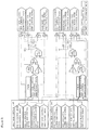
- FIG. 1 is a diagram illustrating a schematic configuration of a system 100 for preventing a contactor from being abnormally opened through a real-time operation detection according to an exemplary embodiment of the present invention.
- FIG. 2 is a schematic circuit diagram of the system 100 for preventing the contactor from being abnormally opened through a real-time operation detection according to the exemplary embodiment of the present invention.
- FIG. 3 is a diagram illustrating a configuration of a main control unit 120 illustrated in FIG. 1 in more detail.
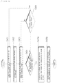
- FIG. 4 is a diagram sequentially illustrating a series of processes for preventing a contactor 1 from being abnormally opened through the system 100 for preventing the contactor from being abnormally opened through a real-time operation detection illustrated in FIG. 1 .
- FIG. 1 is a diagram illustrating a schematic configuration of a system 100 for preventing a contactor from being abnormally opened through a real-time operation detection according to an exemplary embodiment of the present invention
- FIG. 2 is a schematic circuit diagram of the system 100 for preventing the contactor from being abnormally opened through a real-time operation detection according to the exemplary embodiment of the present invention
- FIG. 3 is a diagram illustrating a configuration of a main control unit 120 illustrated in FIG. 1 in more detail.
- the system 100 for preventing a contactor from being abnormally opened through a real-time operation detection may generally include a contactor coil control unit 110 and a main control unit 120 , and the main control unit 120 may additionally include first and second main control units 120 a and 120 b.
- the contactor coil control unit 110 may serve to apply an operation signal to a contactor coil 2 provided in a contactor 1 which connects a battery (not illustrated) and an inverter (not illustrated).
- the contactor 1 may generally mean a switching element which conducts or blocks a current flowing between the battery and the inverter between the battery and the inverter, and may be collectively called a relay.
- the contactor 1 may be implemented with a contact point (not illustrated) and the contactor coil 1 , when the contactor coil control unit 110 applies an operation signal (the operation signal may be an on or off signal, or a power application signal for initiating an on/off operation) to the contactor coil 1 , electromagnetic force is generated in the contactor coil 2 , so that the current may be conducted while the contact points are in contact with each other.
- an operation signal the operation signal may be an on or off signal, or a power application signal for initiating an on/off operation
- the main control unit 120 which is to be described below may detect the abnormal signal in real time.
- the contactor 1 , the contactor coil 2 , and the contactor coil control unit 110 described in the present specification use the publicly known technologies in the related art, so that detailed descriptions thereof will be omitted.
- the main control unit 120 may execute a first detection mode in order to detect the contactor coil control unit 110 in real time, and when it is determined that the applied operation signal is an abnormal signal, the main control unit 120 may execute a second detection mode, and the main control unit 120 may serve to directly control an operation state of the contactor coil 2 based on a maintenance time of the abnormal signal and forcibly open a state of the contact point of the contactor 1 or forcibly maintain a connection state.
- the first detection mode may be a normal mode executed when the contactor coil control unit 110 applies the operation signal (in this case, the operation signal may be a normal signal or an abnormal signal), and the second detection mode may be a maintenance mode executed for maintaining a connection state of the contact point of the contactor 1 for a predetermined time in order to prevent the contact point of the contactor 1 from being unexpectedly opened by the abnormal signal.
- the operation signal may be a normal signal or an abnormal signal
- the second detection mode may be a maintenance mode executed for maintaining a connection state of the contact point of the contactor 1 for a predetermined time in order to prevent the contact point of the contactor 1 from being unexpectedly opened by the abnormal signal.
- the case where the first detection mode is executed may mean that the normal signal (for example, a signal enabling the contact point of the contactor 1 to be operated in a connection state during the travelling of the vehicle) is presently applied from the contactor coil control unit 110 and electromagnetic force is generated in the contactor coil 2
- the case where the second detection mode is executed may mean that the abnormal signal (for example, a signal allowing the contact point of the contactor 1 to be unexpectedly operated in an open state during the travelling of the vehicle) is presently applied from the contactor coil control unit 110 and electromagnetic force generated in the contactor coil 2 is removable.
- the main control unit 120 may set a counting time for maintaining the connection state of the contact point of the contactor 1 for a predetermined time.
- the counting time may be changed according to a setting by a user as much as possible, and the present invention will be described below based on five seconds of the counting time as an example.
- the main control unit 120 compares the maintenance time of four seconds with a predetermined counting time of five seconds, determines that the abnormal signal is removed before the maintenance time reaches the counting time, and then determines whether the normal signal is applied from the contactor coil control unit 110 .
- the main control unit 120 determines that a failure of the contactor coil control unit 110 is recovered and executes the first detection mode again, and detects whether an abnormal signal of the contactor coil control unit 110 is applied again in real time.
- the main control unit 120 compares the maintenance time of five seconds with the predetermined counting time of five seconds and determines that the contactor coil control unit 110 is currently in a failure state.
- the main control unit 120 determines that a normal operation of the vehicle is impossible, generates an alarm signal which may notify a user that an operation of the vehicle will stop by forcibly opening the contact point of the contactor 1 in advance, and provides the generated alarm signal to a dash board of the vehicle or a user terminal, and then the main control unit 120 stops the operation of the vehicle by forcibly opening the contact point of the contactor 1 , thereby preventing a safety accident due to the abnormal operation of the vehicle.
- the main control unit 120 may determine whether the vehicle is operated in real time based on an output voltage of the battery (not illustrated) and a driving state of the motor (not illustrated) during the execution of the second detection mode, and when it is determined that the vehicle is currently operated as a result of the determination, the main control unit 120 may set the counting time.
- the reason is to remove a risk factor according to a vehicle sudden stop and the like incurrable when the abnormal signal is applied from the contactor coil control unit 110 and a conduction state of the motor is blocked in the vehicle that is being operated at a high speed.
- the present invention may autonomously adjust whether to forcibly open the contact point of the relay 1 according to whether the vehicle is actually operated and defer the opening of the contact point for a predetermined time, so that it is possible to prevent a sudden stop of the vehicle due to a sudden stop of the motor and the like.
- the main control unit 120 may determine whether the abnormal signal is a signal generated by a temporary external impact of the vehicle or a signal generated by an actual failure of the contactor coil control unit 110 based on the maintenance time of the abnormal signal applied from the contactor coil control unit 110 during the execution of the second detection mode, and deal with the abnormal signal during the travelling of the vehicle, so that even though the abnormal signal is applied in a vehicle that is being operated at a high speed, it is possible to accurately determine a reason of the application of the abnormal signal and accurately determine whether to stop or maintain an operation of the vehicle.
- the main control unit 120 may include the first main control unit 120 a connectable to a terminal (for example, a positive (+) terminal) at one side of the contactor coil 2 and the second main control unit 120 b connectable to a terminal (for example, a negative ( ⁇ ) terminal) at the other side of the contactor coil 2 , and in this case, the first main control unit 120 a may be connected between the contactor coil 2 and a contactor power supply (not illustrated) that supplies power to the contactor coil 2 and control a current supplied to the contactor coil 2 , and the second main control unit 120 b may be connected between the contactor coil 2 and a ground GND and serve to control a ground state of the contactor coil 2 , and as a result, the main control unit 120 may directly control an operation state of the contactor coil 2 through the first and second main control units 120 a and 120 b.
- the present invention may further include a voltage determining unit (not illustrated) which measures a voltage of the battery (not illustrated) and a voltage of the inverter (not illustrated) according to the operation signal applied from the contactor coil control unit 120 , and a current determining unit (not illustrated) which measures a current flowing between the battery and the inverter according to the operation signal applied from the contactor coil control unit 110 .
- the main control unit 120 may determine whether the operation signal applied from the contactor coil control unit 110 is a normal signal or an abnormal signal based on the measured current and a voltage difference between the battery and the inverter.
- FIG. 4 is a diagram sequentially illustrating a series of processes for preventing the contactor 1 from being abnormally opened through the system 100 for preventing the contactor from being abnormally opened through a real-time operation detection illustrated in FIG. 1 .
- the contactor coil control unit 110 applies an operation signal to the contactor coil 2 and electromagnetic force is generated in the contactor coil 2 , the contact point of the contactor 1 is connected (closed), and the main control unit 120 executes the first detection mode for detecting the signal applied from the contactor coil control unit 110 and an operation state of the contactor coil 2 in real time (S 401 ).
- the main control unit 120 detects whether an abnormal signal is applied from the contactor coil control unit 110 (S 402 ), and when the abnormal signal is applied, a second detection mode for comparing a maintenance time of the corresponding abnormal signal is executed (S 403 ).
- the main control unit 120 determines whether the maintenance time of the abnormal signal applied from the contactor coil control unit 110 exceeds a predetermined counting time (S 404 ), and when it is determined that the maintenance time of the abnormal signal applied from the contactor coil control unit 110 exceeds the predetermined counting time, the main control unit 120 and notifies the vehicle or a user of an alarm signal in advance by providing the alarm signal to a dash board of the vehicle or a user terminal (S 405 a ), and power applied to the contactor coil 2 is blocked through the first and second main control units 120 a and 120 b to stop the generation of electromagnetic force of the contactor coil 2 and forcibly open the contact point of the contactor 1 (S 405 b ).
- the main control unit 120 determines whether the failure of the contactor coil control unit 110 is recovered through whether a normal signal is applied from the contactor coil control unit 110 (S 406 ), and when it is determined that the failure is completely recovered, the main control unit 120 is executed with the first detection mode from the second detection mode, and when it is determined that the failure is not completely recovered, the main control unit 120 compares the maintenance time of the abnormal signal applied from the contactor coil control unit 110 again while maintaining the execution of the second detection mode.
Landscapes
- Engineering & Computer Science (AREA)
- Mechanical Engineering (AREA)
- General Physics & Mathematics (AREA)
- Physics & Mathematics (AREA)
- Power Engineering (AREA)
- Transportation (AREA)
- Sustainable Energy (AREA)
- Life Sciences & Earth Sciences (AREA)
- Sustainable Development (AREA)
- Chemical & Material Sciences (AREA)
- Combustion & Propulsion (AREA)
- Automation & Control Theory (AREA)
- Electric Propulsion And Braking For Vehicles (AREA)
- Protection Of Static Devices (AREA)
- Relay Circuits (AREA)
Applications Claiming Priority (3)
| Application Number | Priority Date | Filing Date | Title |
|---|---|---|---|
| KR10-2016-0090276 | 2016-07-15 | ||
| KR1020160090276A KR102121639B1 (ko) | 2016-07-15 | 2016-07-15 | 실시간 동작 감지를 통한 컨텍터의 비정상 개방 방지 시스템 및 방법 |
| PCT/KR2017/000823 WO2018012696A1 (ko) | 2016-07-15 | 2017-01-24 | 실시간 동작 감지를 통한 컨텍터의 비정상 개방 방지 시스템 및 방법 |
Publications (2)
| Publication Number | Publication Date |
|---|---|
| US20200124672A1 US20200124672A1 (en) | 2020-04-23 |
| US10746802B2 true US10746802B2 (en) | 2020-08-18 |
Family
ID=60953182
Family Applications (1)
| Application Number | Title | Priority Date | Filing Date |
|---|---|---|---|
| US16/066,239 Active 2037-08-03 US10746802B2 (en) | 2016-07-15 | 2017-01-24 | System and method for preventing abnormal opening of contactor through real-time operation detection |
Country Status (7)
| Country | Link |
|---|---|
| US (1) | US10746802B2 (de) |
| EP (1) | EP3385108B1 (de) |
| JP (1) | JP6638069B2 (de) |
| KR (1) | KR102121639B1 (de) |
| CN (1) | CN108473059B (de) |
| PL (1) | PL3385108T3 (de) |
| WO (1) | WO2018012696A1 (de) |
Cited By (2)
| Publication number | Priority date | Publication date | Assignee | Title |
|---|---|---|---|---|
| US11451049B2 (en) | 2019-11-15 | 2022-09-20 | Samsung Sdi Co., Ltd. | Device for maintaining operating state of contactor |
| EP4425524A1 (de) * | 2023-03-03 | 2024-09-04 | Samsung SDI Co., Ltd. | Schaltsteuerungsvorrichtung, batteriepack sowie fahrzeug damit |
Families Citing this family (15)
| Publication number | Priority date | Publication date | Assignee | Title |
|---|---|---|---|---|
| KR102515607B1 (ko) * | 2018-05-28 | 2023-03-28 | 삼성에스디아이 주식회사 | 스위치 제어 회로 및 이를 포함하는 배터리 팩 |
| KR102447096B1 (ko) * | 2018-09-28 | 2022-09-23 | 주식회사 엘지에너지솔루션 | 플립플롭을 이용한 릴레이 제어 시스템 및 방법 |
| CN110047691B (zh) * | 2019-04-18 | 2021-08-20 | 首钢京唐钢铁联合有限责任公司 | 一种电力隔离开关和电力接线隔离装置 |
| KR20210133028A (ko) * | 2020-04-28 | 2021-11-05 | 에너테크인터내셔널 주식회사 | 배터리 제어 장치 및 그 방법 |
| CN113752838B (zh) | 2020-05-29 | 2023-10-03 | 宁德时代新能源科技股份有限公司 | 一种驱动电路 |
| CN113746462B (zh) | 2020-05-29 | 2024-04-05 | 宁德时代新能源科技股份有限公司 | 一种驱动电路 |
| KR20220012044A (ko) * | 2020-07-22 | 2022-02-03 | 주식회사 엘지에너지솔루션 | 배터리 장치, 배터리 관리 시스템 및 컨택터 공급 전압 진단 방법 |
| KR102833786B1 (ko) | 2020-08-20 | 2025-07-11 | 주식회사 엘지에너지솔루션 | 콘택터 관리 방법 및 그 방법을 제공하는 배터리 시스템 |
| JP2023541631A (ja) | 2020-09-15 | 2023-10-03 | センサータ テクノロジーズ インコーポレーテッド | 接触器における故障モード検出 |
| CN112277647B (zh) * | 2020-10-30 | 2021-11-05 | 蜂巢能源科技有限公司 | 电池管理系统及车辆 |
| KR20220114976A (ko) * | 2021-02-09 | 2022-08-17 | 주식회사 엘지에너지솔루션 | 전원 공급 관리 장치 및 그것의 동작 방법 |
| FR3138561A1 (fr) * | 2022-07-26 | 2024-02-02 | Psa Automobiles Sa | Ensemble electrique pour securiser un reseau electrique haute tension d’un vehicule automobile electrifie |
| KR20240018853A (ko) * | 2022-08-03 | 2024-02-14 | 주식회사 엘지에너지솔루션 | 배터리 시스템의 진단 장치 및 방법 |
| KR20240130496A (ko) | 2023-02-22 | 2024-08-29 | 삼성에스디아이 주식회사 | 스위치 제어 장치 및 이를 포함하는 배터리 팩 |
| KR20250064507A (ko) * | 2023-11-02 | 2025-05-09 | 삼성에스디아이 주식회사 | 리텐션 회로 진단 방법 및 시스템 |
Citations (14)
| Publication number | Priority date | Publication date | Assignee | Title |
|---|---|---|---|---|
| JPH05316743A (ja) | 1992-05-07 | 1993-11-26 | Toyota Motor Corp | インバータ駆動制御装置 |
| JPH0937405A (ja) | 1995-07-19 | 1997-02-07 | Hitachi Ltd | 電気車の電動機制御装置用の自己診断装置 |
| JPH09172781A (ja) | 1995-12-15 | 1997-06-30 | Denso Corp | 電気自動車走行用モータ制御装置 |
| KR20000045987A (ko) | 1998-12-31 | 2000-07-25 | 추호석 | 아이지비티 스위칭소자용 게이트 드라이버 및 이의제어방법 |
| JP2006121865A (ja) | 2004-10-25 | 2006-05-11 | Panasonic Ev Energy Co Ltd | 電動車輌のコンタクタ制御装置、コンタクタ制御方法、そのプログラム及びコンピュータ可読記録媒体 |
| JP2006311640A (ja) | 2005-04-26 | 2006-11-09 | Toyota Motor Corp | 車両の電源回路装置 |
| JP2010041821A (ja) | 2008-08-05 | 2010-02-18 | Suzuki Motor Corp | 交流電動機の制御装置 |
| US20120020136A1 (en) * | 2009-03-03 | 2012-01-26 | Hitachi Automotive Systems. Ltd. | Electric Power Conversion System |
| JP2014003742A (ja) | 2012-06-15 | 2014-01-09 | Denso Corp | 電池監視装置 |
| KR20140029800A (ko) | 2012-08-30 | 2014-03-11 | 삼성에스디아이 주식회사 | 배터리 관리 시스템 |
| US20140356686A1 (en) | 2013-05-29 | 2014-12-04 | GM Global Technology Operations LLC | High-voltage contactor switching systems and methods |
| US20160261127A1 (en) * | 2014-08-26 | 2016-09-08 | Elite Power Innovations, Llc | Method and system for battery management |
| US20160372940A1 (en) * | 2013-11-22 | 2016-12-22 | H-Tech Ag | Battery Management System for Controlling an Energy Storage Assembly and Method for Charging and Discharging an Energy Storage Assembly |
| US20180166244A1 (en) * | 2015-07-01 | 2018-06-14 | Panasonic Intellectual Property Management Co., Ltd. | Electromagnetic relay |
Family Cites Families (10)
| Publication number | Priority date | Publication date | Assignee | Title |
|---|---|---|---|---|
| JPH10271612A (ja) * | 1997-03-24 | 1998-10-09 | Komatsu Ltd | 電気駆動機械のコンタクタ駆動制御装置 |
| JP4835351B2 (ja) * | 2005-12-28 | 2011-12-14 | アンデン株式会社 | リレー駆動回路 |
| JP2007228777A (ja) * | 2006-02-27 | 2007-09-06 | Toyota Motor Corp | 電源制御装置および車両 |
| JP4788461B2 (ja) * | 2006-04-24 | 2011-10-05 | トヨタ自動車株式会社 | 電源制御装置およびリレーの異常検出方法 |
| JP5393318B2 (ja) | 2009-07-28 | 2014-01-22 | キヤノン株式会社 | 位置姿勢計測方法及び装置 |
| JP5575506B2 (ja) * | 2010-02-26 | 2014-08-20 | 三洋電機株式会社 | 車両用電源装置及びこの電源装置を備える車両 |
| JP5290228B2 (ja) * | 2010-03-30 | 2013-09-18 | 株式会社日本自動車部品総合研究所 | 電圧検出器、異常検出装置、非接触送電装置、非接触受電装置、非接触給電システムおよび車両 |
| JP5724866B2 (ja) * | 2011-12-19 | 2015-05-27 | トヨタ自動車株式会社 | 監視システムおよび監視方法 |
| US8861161B2 (en) * | 2012-06-29 | 2014-10-14 | Lg Chem, Ltd. | Driver circuit for an electric vehicle and a diagnostic method for determining when first and second voltage drivers are shorted to a high voltage |
| CN203005111U (zh) * | 2012-11-14 | 2013-06-19 | 浙江吉利汽车研究院有限公司杭州分公司 | 一种电动汽车延时断电装置 |
-
2016
- 2016-07-15 KR KR1020160090276A patent/KR102121639B1/ko active Active
-
2017
- 2017-01-24 US US16/066,239 patent/US10746802B2/en active Active
- 2017-01-24 PL PL17827770T patent/PL3385108T3/pl unknown
- 2017-01-24 CN CN201780006266.9A patent/CN108473059B/zh active Active
- 2017-01-24 WO PCT/KR2017/000823 patent/WO2018012696A1/ko not_active Ceased
- 2017-01-24 JP JP2018532717A patent/JP6638069B2/ja active Active
- 2017-01-24 EP EP17827770.3A patent/EP3385108B1/de active Active
Patent Citations (15)
| Publication number | Priority date | Publication date | Assignee | Title |
|---|---|---|---|---|
| JPH05316743A (ja) | 1992-05-07 | 1993-11-26 | Toyota Motor Corp | インバータ駆動制御装置 |
| JPH0937405A (ja) | 1995-07-19 | 1997-02-07 | Hitachi Ltd | 電気車の電動機制御装置用の自己診断装置 |
| JPH09172781A (ja) | 1995-12-15 | 1997-06-30 | Denso Corp | 電気自動車走行用モータ制御装置 |
| KR20000045987A (ko) | 1998-12-31 | 2000-07-25 | 추호석 | 아이지비티 스위칭소자용 게이트 드라이버 및 이의제어방법 |
| JP2006121865A (ja) | 2004-10-25 | 2006-05-11 | Panasonic Ev Energy Co Ltd | 電動車輌のコンタクタ制御装置、コンタクタ制御方法、そのプログラム及びコンピュータ可読記録媒体 |
| JP2006311640A (ja) | 2005-04-26 | 2006-11-09 | Toyota Motor Corp | 車両の電源回路装置 |
| JP2010041821A (ja) | 2008-08-05 | 2010-02-18 | Suzuki Motor Corp | 交流電動機の制御装置 |
| US20120020136A1 (en) * | 2009-03-03 | 2012-01-26 | Hitachi Automotive Systems. Ltd. | Electric Power Conversion System |
| JP2014003742A (ja) | 2012-06-15 | 2014-01-09 | Denso Corp | 電池監視装置 |
| KR20140029800A (ko) | 2012-08-30 | 2014-03-11 | 삼성에스디아이 주식회사 | 배터리 관리 시스템 |
| US9054538B2 (en) | 2012-08-30 | 2015-06-09 | Samsung Sdi Co., Ltd. | Battery management system |
| US20140356686A1 (en) | 2013-05-29 | 2014-12-04 | GM Global Technology Operations LLC | High-voltage contactor switching systems and methods |
| US20160372940A1 (en) * | 2013-11-22 | 2016-12-22 | H-Tech Ag | Battery Management System for Controlling an Energy Storage Assembly and Method for Charging and Discharging an Energy Storage Assembly |
| US20160261127A1 (en) * | 2014-08-26 | 2016-09-08 | Elite Power Innovations, Llc | Method and system for battery management |
| US20180166244A1 (en) * | 2015-07-01 | 2018-06-14 | Panasonic Intellectual Property Management Co., Ltd. | Electromagnetic relay |
Non-Patent Citations (1)
| Title |
|---|
| International Search Report for PCT/KR2017/000823 (PCT/ISA/210) dated Apr. 19, 2017. |
Cited By (4)
| Publication number | Priority date | Publication date | Assignee | Title |
|---|---|---|---|---|
| US11451049B2 (en) | 2019-11-15 | 2022-09-20 | Samsung Sdi Co., Ltd. | Device for maintaining operating state of contactor |
| EP4425524A1 (de) * | 2023-03-03 | 2024-09-04 | Samsung SDI Co., Ltd. | Schaltsteuerungsvorrichtung, batteriepack sowie fahrzeug damit |
| US20240297001A1 (en) * | 2023-03-03 | 2024-09-05 | Samsung Sdi Co., Ltd. | Switch control device, and battery pack and vehicle including the same |
| US12387885B2 (en) * | 2023-03-03 | 2025-08-12 | Samsung Sdi Co., Ltd. | Switch control device, and battery pack and vehicle including the same |
Also Published As
| Publication number | Publication date |
|---|---|
| CN108473059B (zh) | 2021-03-16 |
| KR20180008224A (ko) | 2018-01-24 |
| KR102121639B1 (ko) | 2020-06-10 |
| PL3385108T3 (pl) | 2020-03-31 |
| US20200124672A1 (en) | 2020-04-23 |
| CN108473059A (zh) | 2018-08-31 |
| JP6638069B2 (ja) | 2020-01-29 |
| EP3385108B1 (de) | 2019-09-18 |
| EP3385108A4 (de) | 2019-02-13 |
| JP2019503162A (ja) | 2019-01-31 |
| WO2018012696A1 (ko) | 2018-01-18 |
| EP3385108A1 (de) | 2018-10-10 |
Similar Documents
| Publication | Publication Date | Title |
|---|---|---|
| US10746802B2 (en) | System and method for preventing abnormal opening of contactor through real-time operation detection | |
| JP6793637B2 (ja) | 電池管理装置、及び電源システム | |
| US10305299B2 (en) | Battery apparatus, vehicle, battery management program, and management method of battery apparatus | |
| US10144298B2 (en) | Power supply device of vehicle | |
| US11532841B2 (en) | Storage battery control device | |
| US10170804B2 (en) | Monitoring device for secondary battery, battery pack, and vehicle | |
| JP6394631B2 (ja) | 電源装置 | |
| US20130229186A1 (en) | Switch failure detection device, battery pack including the same, and method of detecting failure of electronic switch | |
| KR101614202B1 (ko) | 전류 측정 릴레이 장치 | |
| CN108028545A (zh) | 车载用电源装置及其控制方法 | |
| KR20150098554A (ko) | 전압 측정을 통한 배터리 랙 파손 방지 장치, 시스템 및 방법 | |
| JP2017079496A (ja) | コンタクタ故障判定装置およびコンタクタ故障判定方法 | |
| US20170207722A1 (en) | Power Conversion Apparatus | |
| KR20210127906A (ko) | 전기 자동차용 배터리 전원 공급 장치 및 방법 | |
| JP2017093008A (ja) | コンタクタ故障判定装置およびコンタクタ故障判定方法 | |
| KR20170062766A (ko) | 배터리의 충전 전압 제어 장치 및 방법 | |
| KR20170142013A (ko) | 논리 연산을 이용한 릴레이 다중 제어 장치 및 방법 | |
| US20190160946A1 (en) | Electrically driven vehicle | |
| KR20200124032A (ko) | 배터리 전류 센서 진단 시스템 및 방법 | |
| EP3392992A1 (de) | System und verfahren zum schutz einer inter-batterie-schaltung anhand eines freilaufpfades | |
| CN110391471B (zh) | 一种电箱自配电路控制系统、方法及电箱和运载工具 | |
| CN116324448A (zh) | 电力供应管理装置及其操作方法 | |
| KR20160045268A (ko) | 배터리 과충전 보호장치 | |
| KR20160081014A (ko) | 과충전 방지 장치 및 방법 |
Legal Events
| Date | Code | Title | Description |
|---|---|---|---|
| FEPP | Fee payment procedure |
Free format text: ENTITY STATUS SET TO UNDISCOUNTED (ORIGINAL EVENT CODE: BIG.); ENTITY STATUS OF PATENT OWNER: LARGE ENTITY |
|
| AS | Assignment |
Owner name: LG CHEM, LTD., KOREA, REPUBLIC OF Free format text: ASSIGNMENT OF ASSIGNORS INTEREST;ASSIGNORS:CHO, HYUNKI;LEE, SANG HOON;PARK, JAEDONG;AND OTHERS;SIGNING DATES FROM 20170123 TO 20170125;REEL/FRAME:046216/0932 |
|
| STPP | Information on status: patent application and granting procedure in general |
Free format text: NOTICE OF ALLOWANCE MAILED -- APPLICATION RECEIVED IN OFFICE OF PUBLICATIONS |
|
| STCF | Information on status: patent grant |
Free format text: PATENTED CASE |
|
| AS | Assignment |
Owner name: LG ENERGY SOLUTION, LTD., KOREA, REPUBLIC OF Free format text: ASSIGNMENT OF ASSIGNORS INTEREST;ASSIGNOR:LG CHEM, LTD.;REEL/FRAME:058295/0068 Effective date: 20211027 |
|
| MAFP | Maintenance fee payment |
Free format text: PAYMENT OF MAINTENANCE FEE, 4TH YEAR, LARGE ENTITY (ORIGINAL EVENT CODE: M1551); ENTITY STATUS OF PATENT OWNER: LARGE ENTITY Year of fee payment: 4 |