US10759014B2 - Adaptive R744 minimum quantity cooling lubrication system - Google Patents
Adaptive R744 minimum quantity cooling lubrication system Download PDFInfo
- Publication number
- US10759014B2 US10759014B2 US16/217,040 US201816217040A US10759014B2 US 10759014 B2 US10759014 B2 US 10759014B2 US 201816217040 A US201816217040 A US 201816217040A US 10759014 B2 US10759014 B2 US 10759014B2
- Authority
- US
- United States
- Prior art keywords
- compressed air
- injection capillary
- liquid
- capillary segment
- cutting tool
- Prior art date
- Legal status (The legal status is an assumption and is not a legal conclusion. Google has not performed a legal analysis and makes no representation as to the accuracy of the status listed.)
- Active, expires
Links
Images




Classifications
-
- B—PERFORMING OPERATIONS; TRANSPORTING
- B23—MACHINE TOOLS; METAL-WORKING NOT OTHERWISE PROVIDED FOR
- B23Q—DETAILS, COMPONENTS, OR ACCESSORIES FOR MACHINE TOOLS, e.g. ARRANGEMENTS FOR COPYING OR CONTROLLING; MACHINE TOOLS IN GENERAL CHARACTERISED BY THE CONSTRUCTION OF PARTICULAR DETAILS OR COMPONENTS; COMBINATIONS OR ASSOCIATIONS OF METAL-WORKING MACHINES, NOT DIRECTED TO A PARTICULAR RESULT
- B23Q11/00—Accessories fitted to machine tools for keeping tools or parts of the machine in good working condition or for cooling work; Safety devices specially combined with or arranged in, or specially adapted for use in connection with, machine tools
- B23Q11/10—Arrangements for cooling or lubricating tools or work
- B23Q11/1038—Arrangements for cooling or lubricating tools or work using cutting liquids with special characteristics, e.g. flow rate, quality
- B23Q11/1053—Arrangements for cooling or lubricating tools or work using cutting liquids with special characteristics, e.g. flow rate, quality using the cutting liquid at specially selected temperatures
-
- B—PERFORMING OPERATIONS; TRANSPORTING
- B23—MACHINE TOOLS; METAL-WORKING NOT OTHERWISE PROVIDED FOR
- B23Q—DETAILS, COMPONENTS, OR ACCESSORIES FOR MACHINE TOOLS, e.g. ARRANGEMENTS FOR COPYING OR CONTROLLING; MACHINE TOOLS IN GENERAL CHARACTERISED BY THE CONSTRUCTION OF PARTICULAR DETAILS OR COMPONENTS; COMBINATIONS OR ASSOCIATIONS OF METAL-WORKING MACHINES, NOT DIRECTED TO A PARTICULAR RESULT
- B23Q11/00—Accessories fitted to machine tools for keeping tools or parts of the machine in good working condition or for cooling work; Safety devices specially combined with or arranged in, or specially adapted for use in connection with, machine tools
- B23Q11/10—Arrangements for cooling or lubricating tools or work
- B23Q11/1038—Arrangements for cooling or lubricating tools or work using cutting liquids with special characteristics, e.g. flow rate, quality
- B23Q11/1046—Arrangements for cooling or lubricating tools or work using cutting liquids with special characteristics, e.g. flow rate, quality using a minimal quantity of lubricant
-
- B—PERFORMING OPERATIONS; TRANSPORTING
- B23—MACHINE TOOLS; METAL-WORKING NOT OTHERWISE PROVIDED FOR
- B23B—TURNING; BORING
- B23B27/00—Tools for turning or boring machines; Tools of a similar kind in general; Accessories therefor
- B23B27/10—Cutting tools with special provision for cooling
-
- C—CHEMISTRY; METALLURGY
- C09—DYES; PAINTS; POLISHES; NATURAL RESINS; ADHESIVES; COMPOSITIONS NOT OTHERWISE PROVIDED FOR; APPLICATIONS OF MATERIALS NOT OTHERWISE PROVIDED FOR
- C09K—MATERIALS FOR MISCELLANEOUS APPLICATIONS, NOT PROVIDED FOR ELSEWHERE
- C09K5/00—Heat-transfer, heat-exchange or heat-storage materials, e.g. refrigerants; Materials for the production of heat or cold by chemical reactions other than by combustion
- C09K5/02—Materials undergoing a change of physical state when used
- C09K5/04—Materials undergoing a change of physical state when used the change of state being from liquid to vapour or vice versa
- C09K5/041—Materials undergoing a change of physical state when used the change of state being from liquid to vapour or vice versa for compression-type refrigeration systems
-
- B—PERFORMING OPERATIONS; TRANSPORTING
- B23—MACHINE TOOLS; METAL-WORKING NOT OTHERWISE PROVIDED FOR
- B23B—TURNING; BORING
- B23B51/00—Tools for drilling machines
- B23B51/06—Drills with lubricating or cooling equipment
-
- B—PERFORMING OPERATIONS; TRANSPORTING
- B23—MACHINE TOOLS; METAL-WORKING NOT OTHERWISE PROVIDED FOR
- B23Q—DETAILS, COMPONENTS, OR ACCESSORIES FOR MACHINE TOOLS, e.g. ARRANGEMENTS FOR COPYING OR CONTROLLING; MACHINE TOOLS IN GENERAL CHARACTERISED BY THE CONSTRUCTION OF PARTICULAR DETAILS OR COMPONENTS; COMBINATIONS OR ASSOCIATIONS OF METAL-WORKING MACHINES, NOT DIRECTED TO A PARTICULAR RESULT
- B23Q11/00—Accessories fitted to machine tools for keeping tools or parts of the machine in good working condition or for cooling work; Safety devices specially combined with or arranged in, or specially adapted for use in connection with, machine tools
- B23Q11/10—Arrangements for cooling or lubricating tools or work
- B23Q11/1015—Arrangements for cooling or lubricating tools or work by supplying a cutting liquid through the spindle
- B23Q11/1023—Tool holders, or tools in general specially adapted for receiving the cutting liquid from the spindle
-
- B—PERFORMING OPERATIONS; TRANSPORTING
- B23—MACHINE TOOLS; METAL-WORKING NOT OTHERWISE PROVIDED FOR
- B23Q—DETAILS, COMPONENTS, OR ACCESSORIES FOR MACHINE TOOLS, e.g. ARRANGEMENTS FOR COPYING OR CONTROLLING; MACHINE TOOLS IN GENERAL CHARACTERISED BY THE CONSTRUCTION OF PARTICULAR DETAILS OR COMPONENTS; COMBINATIONS OR ASSOCIATIONS OF METAL-WORKING MACHINES, NOT DIRECTED TO A PARTICULAR RESULT
- B23Q11/00—Accessories fitted to machine tools for keeping tools or parts of the machine in good working condition or for cooling work; Safety devices specially combined with or arranged in, or specially adapted for use in connection with, machine tools
- B23Q11/10—Arrangements for cooling or lubricating tools or work
- B23Q11/1038—Arrangements for cooling or lubricating tools or work using cutting liquids with special characteristics, e.g. flow rate, quality
-
- B—PERFORMING OPERATIONS; TRANSPORTING
- B23—MACHINE TOOLS; METAL-WORKING NOT OTHERWISE PROVIDED FOR
- B23Q—DETAILS, COMPONENTS, OR ACCESSORIES FOR MACHINE TOOLS, e.g. ARRANGEMENTS FOR COPYING OR CONTROLLING; MACHINE TOOLS IN GENERAL CHARACTERISED BY THE CONSTRUCTION OF PARTICULAR DETAILS OR COMPONENTS; COMBINATIONS OR ASSOCIATIONS OF METAL-WORKING MACHINES, NOT DIRECTED TO A PARTICULAR RESULT
- B23Q11/00—Accessories fitted to machine tools for keeping tools or parts of the machine in good working condition or for cooling work; Safety devices specially combined with or arranged in, or specially adapted for use in connection with, machine tools
- B23Q11/10—Arrangements for cooling or lubricating tools or work
- B23Q11/1038—Arrangements for cooling or lubricating tools or work using cutting liquids with special characteristics, e.g. flow rate, quality
- B23Q11/1061—Arrangements for cooling or lubricating tools or work using cutting liquids with special characteristics, e.g. flow rate, quality using cutting liquids with specially selected composition or state of aggregation
-
- C—CHEMISTRY; METALLURGY
- C09—DYES; PAINTS; POLISHES; NATURAL RESINS; ADHESIVES; COMPOSITIONS NOT OTHERWISE PROVIDED FOR; APPLICATIONS OF MATERIALS NOT OTHERWISE PROVIDED FOR
- C09K—MATERIALS FOR MISCELLANEOUS APPLICATIONS, NOT PROVIDED FOR ELSEWHERE
- C09K2205/00—Aspects relating to compounds used in compression type refrigeration systems
- C09K2205/10—Components
- C09K2205/106—Carbon dioxide
-
- C—CHEMISTRY; METALLURGY
- C09—DYES; PAINTS; POLISHES; NATURAL RESINS; ADHESIVES; COMPOSITIONS NOT OTHERWISE PROVIDED FOR; APPLICATIONS OF MATERIALS NOT OTHERWISE PROVIDED FOR
- C09K—MATERIALS FOR MISCELLANEOUS APPLICATIONS, NOT PROVIDED FOR ELSEWHERE
- C09K5/00—Heat-transfer, heat-exchange or heat-storage materials, e.g. refrigerants; Materials for the production of heat or cold by chemical reactions other than by combustion
- C09K5/02—Materials undergoing a change of physical state when used
- C09K5/04—Materials undergoing a change of physical state when used the change of state being from liquid to vapour or vice versa
- C09K5/041—Materials undergoing a change of physical state when used the change of state being from liquid to vapour or vice versa for compression-type refrigeration systems
- C09K5/042—Materials undergoing a change of physical state when used the change of state being from liquid to vapour or vice versa for compression-type refrigeration systems comprising compounds containing carbon and hydrogen only
-
- Y—GENERAL TAGGING OF NEW TECHNOLOGICAL DEVELOPMENTS; GENERAL TAGGING OF CROSS-SECTIONAL TECHNOLOGIES SPANNING OVER SEVERAL SECTIONS OF THE IPC; TECHNICAL SUBJECTS COVERED BY FORMER USPC CROSS-REFERENCE ART COLLECTIONS [XRACs] AND DIGESTS
- Y02—TECHNOLOGIES OR APPLICATIONS FOR MITIGATION OR ADAPTATION AGAINST CLIMATE CHANGE
- Y02P—CLIMATE CHANGE MITIGATION TECHNOLOGIES IN THE PRODUCTION OR PROCESSING OF GOODS
- Y02P70/00—Climate change mitigation technologies in the production process for final industrial or consumer products
- Y02P70/10—Greenhouse gas [GHG] capture, material saving, heat recovery or other energy efficient measures, e.g. motor control, characterised by manufacturing processes, e.g. for rolling metal or metal working
Definitions
- a conventional method for delivering a cooling-lubricating spray during a machining process involves the application of a flooded coolant—typically an aqueous oil emulsion—under low to high pressure through a ported spindle and cutting tool.
- a flooded coolant typically an aqueous oil emulsion
- MQL eco-friendly minimum quantity lubrication
- MQCL newer minimum quantity cooling lubrication
- Challenges include pooling of oil droplets in transit within delivery channels and insufficient cooling provided by a carrier fluid such as air.
- Adapting internal MQCL spray jets within the machining system is also very challenging due to for example the inability to maintain the MQCL spray precisely pointed on the cutting zone following various tool change or part change operations.
- Portable and open-air machining tools for example portable drilling tools and knee mills, do not typically utilize flood coolant-lubricant schemes and rely heavily upon MQL and MQCL methods such as oil-air mist, cold air guns, and near-cryogenic sprays.
- MQL and MQCL methods such as oil-air mist, cold air guns, and near-cryogenic sprays.
- R744 MQCL Refrigerant 744
- the present invention uses the term “Open System” to describe R744 MQCL spray-at-tool schemes under ambient atmospheric conditions and “Closed System” to describe R744 MQCL spray-through-spindle and tool schemes under elevated internal air pressure conditions.
- Bio-based machining oils and blends for example Boelube® 70104, a proprietary blend of Oleyl and Cetyl alcohol developed by the Boeing Company, provide excellent lubrication for machining difficult materials such as titanium and carbon fiber reinforced polymer (CFRP), and sandwiched composites of same.
- CFRP titanium and carbon fiber reinforced polymer
- these lubricants do not provide appreciable cooling capacity to manage machining heat. Poor cooling constrains the productivity of the machining process in terms of speed, feed rate, and depth of cut (DOC).
- DOC depth of cut
- oil, water, surfactant and other additives are used to formulate cooling-lubricating mixtures which are applied as a flood or mist coolant-lubricant into the cutting operation.
- use of such cooling-lubricating fluid sprays even at the levels used in conventional MQCL processes, can be very messy and clean-up of surfaces following machining operations can be very challenging particularly where water-based MQCL is used.
- cooling-lubricating schemes for MQCL typically involve small amounts of straight oil in air, cold air, or R744 MQCL sprays, for example as taught by the first named inventor in exemplary U.S. Pat. Nos. 5,725,154, 7,451,941, and 8,926,858.
- a through-ported machining spindle and cutting tool system can be conceptualized as a dynamic pressure reactor within which exists variable pressures and temperatures, fluids, and flow rates.
- the tool coolant port diameter determines the flow rate for the system (for a given pressure)—behaving as a changeable throttle for the machining fluid atmospheres introduced into the interior of the system (spindle and tool).
- injecting and mixing variable amounts of CO 2 , oils and air have proven very problematic due to a multiplicity of tool port diameters and machining conditions, for which any change alters the dynamics of the system, and in particular CO 2 phase transition and fluid mixing behaviors.
- optimal portable drilling conditions required to obtain optimal surface finishes and tool life for sandwiched composite fiber reinforced polymer (CFRP) and Titanium (Ti), termed stack-ups requires changes in drilling speed and/or feed rate for the different materials.
- This capability is provided in portable drilling tools supplied by Apex Tool Group, Lexington, S.C., termed “Adaptive Drilling” technology, and is discussed under U.S. Pat. Nos. 8,277,154 and 8,317,437.
- optimal machining conditions also require optimal drilling atmospheres—specifically cooling and lubrication chemistry, temperature, and pressure conditions. To date there is no effective and reliable solution for dynamically or adaptively monitoring, changing, and stabilizing R744 MQCL atmospheres within open or closed machining systems.
- the first named inventor has developed an internal overpressure scheme (i.e., 100 psi and higher) using for example a CO 2 gas atmosphere within the through-ported spindle and cutting tool, into which various quantities of solid CO 2 and oil are injected and mixed.
- This approach does improve performance but does not completely resolve oil gelation problems.
- high pressure conditions can be problematic and dangerous for machine tool operators, and particularly with portable drilling equipment.
- higher internal pressures require bulky high pressure lines and cause premature rotary seal wear and failure.
- Higher internal pressures utilize significantly more fluids (i.e., air and CO 2 ).
- machining chips and debris are ejected from the cutting zone at higher velocities which requires additional safety measures.
- Vertrel® XF is a fluorocarbon solvent offered by DuPont which can be blended with lubricating oils to provide an evaporative cooling and lubricating mixture.
- the Vertrel® process is too expensive to use in a total loss MQCL machining application.
- the use of many of these conventional volatile solvent-oil cooling-lubricant schemes in productive machining applications are not permitted by manufacturers due to a combination of employee exposure and environmental quality concerns.
- PC propylene carbonate
- PC possesses a very high surface tension—41 dynes/cm—which decreases wettability and requires the addition of a surfactant to lower fluid surface tension for machining applications involving for example low surface energy and non-polar carbon fiber reinforced polymer (CFRP), with a surface energy of approximately 58 dynes/cm.
- CFRP non-polar carbon fiber reinforced polymer
- PC is non-volatile and poses an entrapment issue, for example in complex machining applications involving aircraft fuselage and wing stack-ups comprising sandwiched panels of CFRP, Titanium, and Aluminum.
- an improved R744 MQCL system that provides a precise low-temperature cooling lubrication process absent of the constraints thus described.
- an improved R744 MQCL system is needed that minimizes post-machining surface clean-up operations.
- an improved R744 MQCL system is needed that can perform better than the conventional approaches; a system that is adaptable to a variety of machining systems and tools, particularly closed-systems such as those found in portable drilling machines; and a system that uses 100% safe and renewable cooling-lubricating chemistries in much smaller quantities than used in conventional MQCL schemes.
- An apparatus for cooling a through-ported cutting tool, which has a through-port diameter, with a source of liquid CO 2 comprising: a compressed air line, which has a compressed air inlet and establishes a flow of compressed air to the cutting tool, and the compressed air line has a first CO 2 injection capillary segment and a second CO 2 injection capillary segment; the first and the second CO 2 injection capillary segments are interconnected to the same source of liquid CO 2 ; the first CO 2 injection capillary segment has a first high pressure valve, and the second CO 2 injection capillary segment has a second high pressure valve, and the source of liquid CO 2 has a third high pressure valve; the first CO 2 injection capillary segment has a first throttle, and the second CO 2 injection capillary segment has a second throttle; the first throttle is smaller than the second throttle; the first CO 2 injection capillary segment terminates near the cutting tool; the second CO 2 injection capillary segment terminates near the compressed air inlet; whereby the third valve and first valve are opened, and an amount of
- This invention presents one preferred embodiment as an apparatus for cooling a through-ported cutting tool, which has a through-port diameter, with a source of liquid CO 2 comprising: a compressed air line, which can have a compressed air inlet and can establish a flow of compressed air to the cutting tool, and the compressed air line can have a first CO 2 injection capillary segment and a second CO 2 injection capillary segment; the first and the second CO 2 injection capillary segments can access, connect or interconnect to the same source of liquid CO 2 ; each CO 2 injection capillary segment can have a high pressure valve or regulator and a throttle, and the source of liquid CO 2 can have a third high pressure valve or regulator; the first throttle can be smaller than the second throttle; the first CO 2 injection capillary segment terminates, ends or releases near the cutting tool; the second CO 2 injection capillary segment terminates, ends or releases near the compressed air inlet; whereby the third valve and first valve are opened, and an amount of liquid CO 2 , which corresponds to the diameter of the through-port of the cutting tool
- the compressed air pressure can be between 30 psi and 500 psi; or the compressed air can flow between 0.5 and 20 scfm; the liquid CO 2 can be injected in the first CO 2 injection capillary segment from a charging pressure of between 900 and 5000 psi and to a recycle pressure of between 400 and 750 psi. In another embodiment, the liquid CO 2 can be injected into the first CO 2 injection capillary segment at a flowrate of between 0.1 lbs./hour and 20 lbs./hour.
- the liquid CO 2 can be injected into the second CO 2 injection capillary segment from a pressure of between 500 and 750 psi and to a pressure, which is equal to the compressed air pressure; a small amount of liquid lubricant can be added, introduced or injected into the second cooling fluid;
- the liquid lubricant can comprise: synthetic oil, semi-synthetic oil, mineral oil, bio-based oil, polyalkylene glycol, polyolester or alcohol;
- the liquid lubricant can be added, introduced or injected into the second cooling fluid at a flowrate of between 10 ml/hour and 250 ml/hour;
- the liquid lubricant can be a fractional solute of a volatile carrier solvent to form a dilute liquid lubricant fluid;
- the volatile carrier solvent can comprise a cyclic volatile methyl siloxane, alcohol, ketone or alkene;
- the liquid lubricant can be co-injected and mixed with the second cooling fluid using a telescoping lance.
- This apparatus can be controlled automatically using a PLC (programmable logic controller), digital timers or pressure switches; the apparatus can be controlled using cutting force data; the first or the second throttles can be adjustable.
- PLC programmable logic controller
- digital timers or pressure switches the apparatus can be controlled using cutting force data; the first or the second throttles can be adjustable.
- An apparatus for cooling a through-ported cutting tool, which has a through-port diameter, with a source of liquid CO 2 comprising: a compressed air line, which has a compressed air inlet and establishes a flow of compressed air to the cutting tool, and the compressed air line has a first CO 2 injection capillary segment and a second CO 2 injection capillary segment; the first and the second CO 2 injection capillary segments are interconnected to the same source of liquid CO 2 ; the first CO 2 injection capillary segment has a first high pressure valve, and the second CO 2 injection capillary segment has a second high pressure valve, and the source of liquid CO 2 has a third high pressure valve; the first CO 2 injection capillary segment has a first throttle, and the second CO 2 injection capillary segment has a second throttle; the first throttle is smaller than the second throttle; the first CO 2 injection capillary segment terminates near the cutting tool; the second CO 2 injection capillary segment terminates near the compressed air inlet; whereby the third valve and first valve are opened, and an amount of
- the present invention addresses numerous constraints of conventional MQCL schemes, including R744-air-oil, air/cold air-oil, and solvent-oil aerosol sprays.
- the present invention is an adaptable R744 MQCL system that produces ultra-lean cooling, cleaning, and lubricating atmospheres for any variety of through-ported spindle-tool systems as well as atmospheric jet spray applications.
- the present invention comprises the following exemplary embodiments and aspects.
- a first embodiment of the present invention is a process and apparatus—a novel R744 refrigeration apparatus and process—for providing precise cooling lubrication fluids for a through-ported cutting tool affixed to a through-ported spindle with drive motor means.
- Exemplary aspects of this first embodiment include the following:
- the first embodiment of the present invention utilizes a novel R744 refrigeration apparatus to produce adjustably cool to very cold cooling-lubrication fluids for machining applications.
- the exemplary R744 refrigerator described herein comprises a coaxial refrigeration tube coupled to a through-ported spindle using a through-ported rotary union. Dry compressed air simultaneously (and isobarically) enters and flows through an inner coaxial refrigeration premix tube and through an outer spindle cavity to form a triaxial coolant-lubricant injection and mixing assembly. Supersaturated CO 2 is selectively injected into the refrigeration premix tube using a micro-capillary throttle contained same to produce a micronized fluid spray which mixes with a portion of the compressed air flowing through the system as described.
- the compressed air also (optionally) contains one or more trace lubricant additives, including a novel low-temperature composition described under the second embodiment herein.
- two isobaric mixed-fluid flow streams are produced and maintained within a spindle—(1) an outer hot fluid stream (Air-Additive) flowing coaxially about an inner cold fluid stream (Air-CO 2 ) flowing within an inner coaxial refrigeration premix tube.
- Supersaturated CO 2 is selectively injected into the inner coaxial refrigeration premix tube at a predetermined distance from its exit which allows the micronized fluids to mix efficiently with a portion of compressed air flowing therein to form a very cold Air-CO 2 premix fluid stream. The injection distance determines the CO 2 -air flow stream premixing period.
- the coaxial refrigeration premix tube may be constructed of a thermal-insulating polymer
- the outer metal surface may be insulated using a suitable polymer sleeve (i.e., shrink tubing) or using a secondary sliding-telescoping sleeve which moves in relation to spindle movement using air power or a spring tensioner.
- coaxial refrigeration tube premix fluid and spindle air-additive fluid are turbulently mixed within a region just prior to the cutting tool ports wherein the R744 MQCL fluid mixture exchanges heat (and active chemistry) with the cutting tool and cutting zone upon discharge from the cutting tool through both convective cooling and radiative cooling (CO 2 -enrichment provides improved IR heat absorption).
- the exemplary R744 refrigeration apparatus utilizes a novel dual throttle, mixed-fluid and open-cycle R744 refrigeration process comprising three stages—Stage 1—Charging, Stage 2—Infusion, and Stage 3—Release-Recycle, described as follows.
- Stage 1 supersaturated CO 2 is injected to a predetermined charging pressure (CP) between 1000 psi and 5000 psi, or higher for a predetermined charging time (CT) of between a few seconds or longer (a frequency based cooling cycle) and for the entire machining operation (continuous cycle) to provide the required primary refrigeration.
- CP predetermined charging pressure
- CT charging time
- Stage 2 the charged fluid is infused (at a frequency or continuously) through a primary fixed micro-throttle having an internal diameter of between 25 microns and 0.015 inches and a length between 6 inches and 36 inches in length, during which micronized CO 2 fluid and particles are precisely mixed with an isolated and coaxial portion of the internal propellant air stream under isobaric compressed air conditions to form a subcooled premix which is then turbulently mixed with another portion of compressed air and lubricant additives.
- Temperatures of the premix fluid decrease from 20 deg. C. to as low as ⁇ 30 deg. C. depending upon the fixed throttle size used, charging pressure, and charging-infusion frequency.
- Stage 3 terminates the primary refrigeration cycle by rapidly recycling residual high pressure CO 2 gas coolant into the upstream compressed air through a second variably-adjusted throttle.
- the majority of the cooling capacity of the exemplary R744 refrigerator is delivered through heats of vaporization and sublimation using a first micro-throttle.
- residual high pressure CO 2 gas can provide additional Joule Thomson (JT) expansion cooling capacity due to a relatively large pressure gradient between the injection throttle and the internal spindle fluid pressures.
- JT Joule Thomson
- Residual high pressure CO 2 gas is a useful cooling agent (convective and radiative cooling), possessing a very large JT coefficient (5 ⁇ greater than compressed air) and an excellent infrared (IR) heat absorption (radiative cooling) capability for cutting zone cooling (i.e., Titanium machining).
- IR infrared
- radiatative cooling radiatative cooling
- cool compressed air convectively removes heat from hot surfaces but does not absorb the significant IR heat emanating from freshly cut surfaces.
- the coolant pressure decreases during the infusion cycle to below 750 psi (i.e., vapor phase) there is an appreciable loss of cooling efficiency as it relates to infusion time using the first micro-throttle (i.e., primary cooling throttle).
- the exemplary R744 refrigerator releases or preferably recycles this high pressure gaseous coolant (referred to herein as spent coolant) rapidly into the propellant air (i.e., recycle) or into ambient atmosphere (i.e., release) through a second and larger adjustable or macro-throttle, following which there is an inter-cycle dwell time (DT). Recycling the CO 2 gas precools the incoming compressed air and increases its radiative cooling properties (vis-à-vis CO 2 enrichment).
- spent coolant gaseous coolant
- DT inter-cycle dwell time
- the RP ranges between 400 psi and 800 psi and the DT ranges between 0 seconds (immediate recycle) to 300 seconds or more (delayed recycle/release or release to ambient pressure).
- the refrigeration cycle thus described is repeated for one or more cycles during a machining operation.
- a variety of refrigeration cycles (and cooling capacities) can be implemented to optimize cooling (and lubrication) for a particular machining operation.
- Exemplary refrigeration cycles include:
- Lower frequency refrigeration cycles work well for small cutting tools with small coolant port diameters.
- Higher frequency or continuous refrigeration cycles work well for larger cutting tools and coolant port diameters.
- a continuous injection cycle i.e., maximum cooling power
- a second embodiment of the present invention is a novel ultra-minimum quantity superspreading lubrication composition for use at low application temperatures.
- Exemplary aspects of this second embodiment include the following:
- VMS volatile methyl siloxane
- D5 decamethylcyclopentasiloxane
- Boelube® 70104 a polar bio-based lubricant
- compositions superspread on both metal and polymer surfaces—depositing increasing thicknesses of Boelube® lubricating films following evaporation of the D5 carrier solvent with increasing concentration of Boelube® solute in the D5 carrier solvent.
- Superspreading behavior has been observed for exemplary mixtures of the present invention on both polar aluminum surfaces and non-polar carbon fiber reinforced polymer (CFRP) surfaces.
- the R744 MQCL composition of the present invention is capable of very low-temperature service with adaptable cooling-lubrication during application.
- compositions of the present embodiment employ only a fraction of the lubricating oil typically used in conventional MQL aerosols—enabling much lower lubricant usage levels of between 1-25 ml Oil/hour as compared to conventional MQL usage levels, typically between 50-150 ml Oil/hour.
- Preferred high-boiling and non-volatile polar lubricants for use in the present embodiment include high-boiling and high molecular weight alcohols such as Oleyl and Cetyl Alcohol, for example as used in an exemplary benchmark lubricant Boelube® 70104, as well as unsaturated bio-esters such as Oleic acid.
- the cyclic VMS carrier solvent significantly reduces the surface tension and viscosity of the lubricating additives—lowering the gel point and improving their flow characteristics under low temperature conditions.
- the VMS solvent carrier separates (evaporates) from the lubricant additives during deposition the surface tension and viscosity of the lubricant additives increase and return to their original levels which accommodates the higher temperature and friction-reducing performance demands of the cutting operation, dynamically adapting to the machining process.
- a range of lubricity levels (and thin film thicknesses) can be formulated as needed for a particular machining application.
- VMS carrier solvent of the present embodiment Another beneficial characteristic of the preferred cyclic VMS carrier solvent of the present embodiment is its high oxygen solubility and resistance to ozone oxidation.
- the preferred VMS carrier solvents of the present invention are useful diluents and mediums for oxygenation processes described in a co-pending invention by the first named inventor and described under U.S. patent application Ser. No. 13/733,880, Method for Forming and Applying an Oxygenated Fluid, which can be used in cooperation with the present invention.
- This second embodiment is particularly directed to resolving icing and clogging problems associated with a through-ported spindle-tool system at very low temperatures using R744 or cold air.
- the present embodiment may also be used as an ultra-lean MQCL agent in an open system jet spray.
- VMS (D5) may be injected directly into liquid carbon dioxide and expanded to form a cold CO 2 -D5 fluid composition which is then mixed with compressed air carrying an oil additive to form a superspreading MQCL cooling-lubricating fluid.
- D6 dodecamethylcyclohexasiloxane
- D5 is particularly advantageous and preferred due to its unique combination of environmental, health, worker safety, availability, cost and physical properties such as a very low melt point, higher volatility and non-flammability.
- D5 is a renewable, environmentally safe, and worker-safe compound suitable for precision cleaning—all of which are very important aspects in machining applications.
- D5 is an EPA SNAP-Approved solvent substitute and is not considered a volatile organic compound (VOC), which exempts the mixtures of the present invention from burdensome regulatory constraints.
- VOC volatile organic compound
- An adaptive CO 2 -based (Refrigerant R744) minimum quantity cooling lubrication (MQCL) system for through-spindle and through-tool machining processes employs a dual-throttle, mixed fluid and open cycle cooling process and apparatus. Moreover, a superspreading lubricant composition is disclosed for use in the present invention as well as conventional minimum quantity lubrication (MQL) processes.
- MQL minimum quantity cooling lubrication
- FIG. 1 a Schott al.
- FIG. 1 b Graph and discussion of operational constraints associated with the conventional R744 MQCL system of FIG. 1 a.
- FIG. 1 c Schematic and description of an exemplary aspects of the improved R744 MQCL system of the present invention.
- FIG. 1 d Graph and discussion of the operational characteristics of the improved R744 MQCL apparatus of FIG. 1 c.
- FIG. 2 Diagram showing various aspects of the R744 MQCL refrigeration cycle used in the present invention.
- FIG. 3 Diagram showing the dual throttling aspect of the R744 MQCL refrigeration cycle used in the present invention.
- FIG. 4 a Graph showing an exemplary change in charging and infusion (capillary) pressure over time for a 1500 psi injection using a 0.008 inch fixed throttle.
- FIG. 4 b Graph showing the change in premix (CO 2 -Air) temperature within the premix tube for the R744 refrigeration cycle of FIG. 4 a.
- FIG. 4 c Graph showing the different cooling mechanisms provided by the R744 MQCL refrigeration cycle used in the present invention at air pressures which are above and below the triple point pressure for CO 2 .
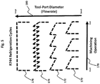
- FIG. 5 Graph showing the different R744 MQCL refrigeration cycles used in the present invention.
- FIG. 6 a Graph showing the cooling capacity provided using an exemplary low frequency R744 refrigeration cycle.
- FIG. 6 b Graph showing the cooling capacity provided using an exemplary high frequency R744 refrigeration cycle.
- FIG. 7 a Graph showing the exemplary range of cooling capacities possible using a 0.008 inch diameter by 16 inch long fixed injection throttle.
- FIG. 7 b Graph showing the exemplary range of cooling capacities possible using a 0.015 inch diameter by 12 inch long fixed injection throttle.
- FIG. 8 a Schott al. 8 a —Schematic and discussion of major subsystems of an exemplary R744 refrigerated cooling lubrication system adapted to a portable drilling machine.
- FIG. 8 b Schott al. 8 a —Schematic and discussion of various components the exemplary R744 refrigerated cooling lubrication system adapted to a portable drilling machine described under FIG. 8 a.
- FIG. 9 Schott al. 9 —Schematic showing of the exemplary refrigeration system components—charger, infuser, premix tube, and optional telescoping premix tube sleeve—positioned and operated within a machining spindle cavity.
- FIGS. 10 a , 10 b and 10 c Schematics showing fluid flow through the exemplary perforated premix tube and sequential movement of the optional telescoping premix tube sleeve assembly described under FIG. 9 .
- FIG. 11 Schott al. 11 —Schematic of exemplary coolant and lubricant fluids generation and delivery system.
- FIG. 12 a Graph showing the relationship between low fluid temperature, increasing viscosity and surface tension, and gel point for conventional (neat) lubricants.
- FIG. 12 b Graph showing the requirement for lower apparent viscosity and surface tension at a lower temperature for a lower gel point temperature.
- FIG. 12 c Graph showing calculated surface tension and viscosity values for a range of VMS (D5) and Boelube® 70104 compositions.
- FIG. 13 Photograph showing the spreading areas for Boelube® 70104, VMS (D5), and a 50:50 (v:v) mixture of D5 and Boelube® 70104 on a CFRP substrate.
- FIG. 14 Photograph showing the enlarged spherical spread of the 50:50 (v:v) mixture of D5 and Boelube® 70104 shown under FIG. 13 .
- FIG. 15 Photograph showing the spreading areas for Boelube® 70104 and a 50:50 (v:v) mixture of D5 and Boelube® 70104 on an Aluminum substrate.
- FIG. 16 Photograph showing the spreading areas for Boelube® 70104 and a 90:10 (v:v) mixture of D5 and Boelube® 70104 on a CFRP substrate.
- FIG. 1 a is a schematic of an exemplary conventional R744 MQCL system.
- pressure- and temperature-regulated compressed air ( 2 ) at a pressure of between 30 and 150 psi and a temperature of between 10 degrees C. and 25 degrees C. is flowed through an automated valve ( 4 ) and into a coaxial delivery line segment ( 6 ) which contains a centrally positioned polyethertherketone (PEEK) capillary tube ( 8 ) for CO 2 fluids delivery, the coaxial tube-in-tube segment thus described may be between 6 inches to 20 feet long, or more.
- PEEK polyethertherketone
- the capillary tube segment ( 8 ) typically uses an inside diameter ranging between 0.020 inches to 0.080 inches, or may be stepped ( 10 )—increasing in inside diameter as it traverses the coaxial segment ( 6 ) to assist with CO 2 particle growth.
- Said mechanical throttling valve ( 18 ) is typically a precision 18-turn needle valve, which may be automated, to vary the CO 2 fluid injection (coolant) flow rate.
- the coaxial CO 2 -Air delivery line thus described is integrated with a through-spindle/tool system ( 22 ), within which the CO 2 is injected into and mixed with the coaxial propellant air to form a cold cooling gas stream ( 24 ) which then enters a through-ported tool (not shown).
- the exemplary prior art system may use an auxiliary coaxial additive capillary tube ( 26 ) for injecting lubricant droplets ( 28 ) into the cold CO 2 -Air mixture ( 24 ) within the through-ported spindle ( 22 ).
- the coolant mixture ( 14 ) traverses relatively large distances through the coaxial segment ( 6 ) before air-additive mixing ( 24 ) within the internal through-ported cavity of the spindle ( 22 ) and then finally into a ported cutting tool (not shown).
- air-additive mixing ( 24 ) within the internal through-ported cavity of the spindle ( 22 ) and then finally into a ported cutting tool (not shown).
- losses in cooling capacity are experienced during the delivery process to the spindle, described below.
- FIG. 1 b is a graph describing operational constraints associated with the conventional R744 MQCL system of FIG. 1 a .
- FIG. 1 b during operation of the prior art system several problems arise. During the injection of CO 2 fluids using a pulsing on/off valve operation ( 30 ), large fluctuations in CO 2 capillary pressure ( 32 ) are experienced.
- One method developed by the first named inventor to suppress the internal pressure fluctuations is to increase the compressed air pressure into the spindle to 100 psi or higher—creating an overpressure condition ( 36 )—which dampers the incoming CO 2 fluid pressure fluctuations.
- overpressure condition 36
- higher spindle air pressures increase wear rates on rotary unions and seals, consume more process fluids (air/CO 2 ), and increase pressure-related hazards such as machining chip and particle velocities.
- Another problem related to CO 2 -Air mixing pressure fluctuations is mixing temperature fluctuations. Fluid mixing pressure variability results in mixing temperature variability ( 38 ).
- the present invention uniquely resolves known constraints associated with conventional R744 MQCL schemes using a comprehensive approach involving two significant embodiments: (1) an improved R744 refrigeration system—including both apparatus and process, and (2) an improved R744 MQCL lubricant additive composition—providing significantly improved physicochemical performance properties under low temperature mixing and application conditions. Both embodiments and aspects related to same are discussed in detail in the following sections.
- FIG. 1 c is a schematic describing exemplary aspects of the improved R744 MQCL system of the present invention.
- the present invention utilizes (in part) a recently patented CO 2 micronizing process developed by the first named inventor, which is described in detail in U.S. Pat. No. 9,221,067, U.S. Patent No. '067, CO 2 Composite Spray Method and Apparatus, Jackson D. et al.
- a (primary or first) fixed microscopic capillary throttle ( 40 ) is positioned on the downstream and terminal side ( 42 ) of a supersaturated CO 2 feed capillary ( 44 ) and affixed centrally within a coaxial compressed air mixing tube ( 46 ) positioned within a through-ported spindle ( 48 ).
- the fixed throttle capillary ( 40 ) is preferably constructed of a segment of stainless steel or PEEK polymer with inside diameters ranging between 25 microns to 0.015 inches, and lengths between 6 inches and 36 inches.
- the supersaturated CO 2 feed capillary ( 44 ) is preferably constructed of high pressure flexible PEEK polymer capable of maintaining supersaturated CO 2 pressures of between 1000 and 5000 psi, and having a length required to interconnect the upstream and exemplary '067 CO 2 generation and supply system with a high pressure supply valve (not shown in FIG.
- the coolant flow rate (and coolant capacity) of the fixed throttle ( 40 ) of FIG. 1 c is adjusted by changing the pressure of the supersaturated CO 2 coolant feed fluid ( 50 ) upstream in the aforementioned exemplary '067 CO 2 generation and supply system with a high pressure supply valve (all of which is not shown in FIG. 1 c ), and is metered into the feed capillary ( 44 ) using a high pressure valve ( 52 ).
- Supersaturated liquid CO 2 ( 50 ) is injected into and flowed through the inside of the feed capillary ( 54 ) at a preferred fluid pressure range of between 1000 and 5000 psi, and at a preferred fluid temperature of between 10 and 25 deg. C.
- changing throttle capillary supersaturation pressure precisely adjusts the coolant injection rates between 0.1 lbs. to 20 lbs. CO 2 /hour, and is dependent upon the throttle capillary design, diameter, configuration, and length, and the type of R744 refrigeration cycle employed discussed herein.
- pressure- and temperature-regulated compressed air ( 56 ) at a feed pressure between 30 and 150 psi, a flowrate between 0.5 and 10 scfm, and a temperature between 10 degrees C. and 25 degrees C. is flowed through an automated 3-way valve ( 58 ) and into a coaxial compressed air delivery line ( 60 ) which also contains the centrally disposed supersaturated CO 2 feed capillary ( 44 ).
- the coaxial tube-in-tube segment thus described may be any length needed to connect R744 MQCL fluids generation and supply system (not shown) with the R744-adapted machining system (not shown).
- Compressed air enters the spindle ( 48 ) through the premix conduit or tube ( 46 ) which has airflow exit perforations ( 62 ) at the entrance portion to allow the compressed air to flow both down the interior of the premix tube ( 46 ) as well out of and down the exterior region ( 64 ) between the inner surface of the spindle and the outer surface of the premix tube ( 46 ). Also shown is an optional telescoping insulating conduit or tube ( 66 ) with air flow entrance perforations ( 68 ) located at the discharge exit.
- the features thus described provide two fluid flow streams—a centralized cold CO 2 -Air premix fluid stream and an outer warmer insulating air stream.
- a key aspect of FIG. 1 c is the use of a secondary adjustable throttle connected to the supersaturated CO 2 feed capillary, and described as follows.
- RP release-recycle pressure
- residual high pressure CO 2 gas i.e., spent coolant
- a predetermined amount of supersaturated and saturated liquid i.e., dense phase
- CO 2 supersaturated and saturated liquid
- the first micro-throttle ( 40 ) is reverse flowed ( 70 ) upstream through a recycle or return capillary tube ( 71 ), 2-way valve ( 72 ), and adjustable micrometering valve ( 74 ), and is injected ( 76 ) and mixed with the upstream compressed air ( 78 )—providing secondary precooling and CO 2 gas enrichment of the air stream ( 78 ).
- the secondary mechanical throttling valve ( 74 ) is preferably a precision 18-turn needle valve, which may be automated to vary the CO 2 fluid recycling (or release) flow rate.
- both CO 2 feed ( 54 ) and air flow ( 74 ) is terminated and all residual fluids contained within the CO 2 feed capillary ( 44 ) and compressed air tube ( 60 ) segments are released to the ambient atmosphere ( 80 ) through recycle tube ( 71 ), 2-way valve ( 72 ), through adjustable throttle ( 74 ), coaxial compressed air delivery tube ( 60 ) and normally open 3-way valve ( 58 ), respectively, to safely de-energize the R744 MQCL system.
- a lubricant injection tube ( 82 ) which is contained within the compressed air delivery tube ( 60 ) for delivering minimal quantities of lubricant additives from a lubrication injection pump (not shown).
- the discharge end of the lubricant tube is positioned within the premix tube ( 46 ) just before the airflow exit perforations ( 62 ).
- FIG. 1 d shows a graph describing new and improved operational characteristics of the present invention.
- FIG. 1 d is a graph depicting key operational characteristics of the improved R744 MQCL apparatus described under of FIG. 1 c .
- Cold premix fluid mixed with precooled and CO 2 -enriched compressed air, and oil-infused air, are flowed into and through a ported cutting tool.
- the R744 refrigeration process is sequenced to provide optimal CO 2 usage, fluid mixing and cooling capacity using different CO 2 fluid states—so-called dense phase CO 2 or dense fluids (supersaturated and saturated liquid) and high pressure gas.
- the present invention uses a refrigeration cycle having three distinct refrigeration stages—(Stage 1) CO 2 charging ( 84 ), (Stage 2) CO 2 infusion ( 86 ), and (Stage 3) CO 2 Release/Recycle ( 88 ).
- Stage 1 CO 2 charging ( 84 ) the internal spindle pressure
- Stage 2 CO 2 infusion ( 86 ) the internal spindle pressure
- Stage 3 CO 2 Release/Recycle ( 88 ) the internal spindle pressure
- the refrigeration cycle may contain a dwell period ( 92 ), followed by additional refrigeration cycles ( 96 ) as needed to maintain predetermined cooling-lubrication conditions for a machining process.
- the improved R744 refrigeration process thus described exhibits much lower internal pressure and temperature variance ( 98 ) over time as compared to the prior art.
- the present invention utilizes a novel dual throttle, mixed-fluid and open-cycle R744 refrigeration cycle comprising three stages—Stage 1: Charging ( 100 ), Stage 2: Infusion ( 102 ) and Stage 3: Release ( 104 ) or Recycle ( 106 ), described as follows.
- Stage 1 ( 100 )
- saturated and supersaturated (dense phase) CO 2 is injected into the CO 2 feed capillary ( FIG.
- the infusion time ( 112 ) is optimized during CO 2 coolant injection, with injection pressures decreasing from an initial charge pressure ( 108 ) to a Release-Recycle Pressure (RP) ( 114 ). Based on a predetermined RP ( 114 ), the spent coolant is recycled ( 106 ) into the upstream compressed air supply stream ( FIG.
- a complete R744 refrigeration cycle comprising Stage 1 ( 100 ), Stage 2 ( 102 ) and Stage 3 ( 106 )
- there is an inter-cycle dwell time (DT) ( 116 ).
- the DT ( 116 ) ranges between 0 seconds (i e, immediate recycle and restart of Stage 1) to 60 seconds, or more (i e, immediate recycle and delayed restart or delayed recycle and restart).
- the RC may be repeated for one or more cycles ( 118 ) during a machining operation.
- a variety of refrigeration cycles can be implemented to optimize cooling capacity for a particular machining operation.
- a key operational aspect of the improved R744 refrigeration process described under FIG. 2 is the use of two throttles—a first pneumatically-adjusted throttle ( 120 ) comprising a micro-capillary which is pneumatically adjusted to provide precise infusion of dense phase CO 2 (supersaturated and saturated CO 2 ) into a portion of the airstream within the spindle followed by a second mechanically-adjusted throttle ( 122 ) which provides a relatively fast recycle (or release) of spent coolant (high pressure CO 2 gas) into the upstream compressed air supply to the exemplary R744 refrigerator (or into the atmosphere during release).
- a first pneumatically-adjusted throttle 120
- a micro-capillary which is pneumatically adjusted to provide precise infusion of dense phase CO 2 (supersaturated and saturated CO 2 ) into a portion of the airstream within the spindle
- a second mechanically-adjusted throttle 122 which provides a relatively fast recycle (or release) of spent coolant (high pressure
- FIG. 4 a a pneumatically operated infusion throttle comprising a 0.008 inch ⁇ 16 inch PEEK micro-capillary and an adjustable recycle throttle comprising an 18-turn micrometering valve (Milli-Mite 1300 Series, 0.047 inch orifice, 0.003 inches/turn) set at 10 turns (0.030 inch orifice) are used to charge, infuse and recycle dense phase CO 2 into a spindle premix tube ( FIG.
- the refrigeration parameters comprise a charge pressure (CP) of 1500 psi, an infusion time (IT) of 230 seconds, and a recycle pressure (RP) of 500 psi.
- supersaturated CO 2 is infused ( 132 ) into the premix tube ( FIG. 1 c ( 46 )) and is mixed with a portion of the incoming compressed air over an IT of 230 seconds.
- supersaturated CO 2 infusion changes to a saturated CO 2 infusion at approximately 850 psi ( 134 ) which continues along a vapor-liquid saturation line for about 60 seconds following which the saturated CO 2 changes to high pressure CO 2 vapor at approximately 750 psi ( 136 ) whereupon the capillary pressure gradually decreases ( 138 ) over the remaining infusion time.
- the residual CO 2 Gas ( 140 ) contained in the feed capillary tube is quickly recycled into the upstream compressed air supply, from a starting pressure of 500 psi to the compressed air pressure of 75 psi.
- FIG. 4 b The premix fluid temperature profile for the refrigeration cycle described under FIG. 4 a is shown in FIG. 4 b .
- a majority of the refrigeration capacity using the refrigeration cycle of FIG. 4 a is provided during the initial 30 second infusion of supersaturated CO 2 , followed by diminishing cooling capacity to the 90 second mark ( 144 ) using saturated CO 2 , and much lower CO 2 gas expansion cooling ( 146 ) thereafter.
- the majority of the refrigeration capacity is delivered during the first 30 to 90 seconds following charging. For this particular single refrigeration cycle and operating parameters, continuing the refrigeration process beyond this point is inefficient.
- a more efficient refrigeration cycle involves rapid recycling of spent CO 2 coolant into the upstream compressed air close to the end of the dense phase CO 2 infusion pressure, followed by a restart of the refrigeration cycle with or without a dwell time. Shorter and more frequent infusion cycles provide the most efficient and precise temperature control during a machining operation.
- FIG. 4 c is a graph showing the different cooling mechanisms provided by the R744 MQCL refrigeration cycle used in the present invention at air pressures which are above and below the triple point pressure for CO 2 .
- Compressed air pressures above the triple point pressure for CO 2 (75 psi, 5.1 atm) tend to suppress the formation of dry ice particles while compressed air pressures below this point tend to favor the formation of dry ice particles.
- saturated CO 2 ( 150 ) compressed to supersaturated CO 2 ( 152 ) is pneumatically throttled ( 154 ) and infused ( 156 ) into a portion of the compressed air to form a cold premix fluid at an air pressure of 100 psi ( 158 ).
- FIG. 5 is a diagram showing different types of refrigeration cycles.
- exemplary refrigeration cycles include:
- cutting tool-port diameter 180
- optimal refrigeration cycle For a given machining operation ( 178 ), a general relationship exists between cutting tool-port diameter ( 180 ) and optimal refrigeration cycle. Lower frequency refrigeration cycles work well for small cutting tools with small coolant ports. Higher frequency or continuous refrigeration cycles work well for larger cutting tools and coolant ports. For example, a continuous injection cycle (i.e., maximum cooling power) would generally not be useful for small cutting tool-port diameters as this could introduce excessive cooling capacity—resulting in possible icing (CO 2 /water ice formation), additive gelation, and/or spindle overpressure conditions (internal spindle-tool cavity pressure rises above incoming propellant air pressure). However, using a smaller fixed throttle and lower charging pressure would mitigate these issues.
- FIGS. 6 a and 6 b Exemplary refrigeration cycles are shown under FIGS. 6 a and 6 b with calculated cooling capacities delivered for the exemplary refrigeration cycles (RC).
- FIG. 6 a shows a low frequency refrigeration cycle using a 0.008 inch diameter by 16 inch long throttle operating at a charging pressure (CP) of 1500 psi ( 190 ), a 60 second infusion time (IT) ( 192 ), and a 60 second dwell time (DT) ( 194 )—delivering about 300 BTU/hr. cooling capacity.
- CP charging pressure
- I 60 second infusion time
- DT 60 second dwell time
- 6 b shows a high frequency refrigeration cycle using a 0.008 inch diameter by 16 inch long throttle operating at a CP of 1500 psi ( 196 ), an IT of 30 seconds ( 198 ), and no dwell time (DT) ( 200 )—delivering about 1400 BTU/hr. cooling capacity.
- Dwell time (DT), infusion throttle diameter (and length), and charging pressure (CP) have a pronounced effect upon the cooling capacity of the R744 refrigeration system of the present invention.
- Dwell time is best understood in terms of a duty cycle—cooling for a period of time and not cooling for a period of time.
- Duty cycle is defined herein as the percentage of the time cooling during a machining process.
- FIG. 7 a and FIG. 7 b show the range of cooling capacities possible in relation to charging pressure (CP) and duty cycles ranging from 6% (pulsed cycle) to 100% (continuous cycle) for 0.008 inch by 16 inch long and 0.015 inch by 12 inch long capillary throttles, respectively.
- a 0.008 inch throttle produces R744 refrigeration capacities between 150 BTU/hour ( 220 ) and 1500 BTU/hour ( 222 ) for charging pressures between 1100 psi ( 224 ) and 1700 psi ( 226 ) and duty cycles between 6% ( 228 ) and 100% ( 230 ), respectively.
- a 0.015 inch throttle produces R744 refrigeration capacities between 200 BTU/hour ( 232 ) and 3000 BTU/hour ( 234 ) for charging pressures between 1100 psi ( 236 ) and 1700 psi ( 238 ) and duty cycles between 6% ( 240 ) and 100% ( 242 ), respectively.
- the optimal refrigeration cycle is determined experimentally and is dependent upon a combination of several key and interrelated machining process variables, including:
- Type(s) of workpiece i.e., Ti, CFRP, Al, and Stack-up configurations.
- Cutting tool geometry and coating i.e., uncoated WC, PCD, TiN, and TiAlN).
- Machining process i.e., drilling, milling, turning.
- Atmosphere i.e., dry, near-dry, level of oxygenation.
- FIG. 8 a is a schematic of major subsystems of an exemplary R744 refrigerated cooling lubrication system of the present invention adapted to a portable drilling machine.
- the R744 MQCL adapted system comprising a R744 refrigeration fluids generator and control system ( 250 ), a R744 refrigerator-applicator system ( 252 ), and a drill motor spindle-tool system ( 254 ).
- Exemplary portable drilling machines i.e., Quackenbush and Recoules systems
- suitable for use with the present invention are available from APEX Tool Group, Lexington, S.C.
- FIG. 8 b provides additional exemplary aspects of the R744 MQCL adapted machining system of FIG. 8 a .
- the exemplary R744 refrigeration fluids generator and control system ( FIG. 8 a ( 250 )) comprises a supply of supersaturated CO 2 ( 260 ) fed through a CO 2 feed tube ( 262 ), a supply of compressed air ( 264 ), and a supply of lubricant additive ( 266 ).
- the exemplary R744 refrigeration fluids generator and control system further comprise a CO 2 fluid recycling plumbing circuit ( 268 ) equipped with a mechanically adjusted throttle ( 270 ) and a CO 2 -air fluids release plumbing circuit ( 272 ).
- the exemplary R744 refrigerator-applicator system ( FIG. 8 a ( 252 )) comprises a rotary union ( 274 ) for accepting said CO 2 capillary feed tube ( 262 ), lubricant additive tube ( 266 ), and compressed air tube ( 264 ) containing same.
- a spindle adaptor ( 276 ) integrates the rotary union ( 274 ), perforated premix tube ( 278 ), fixed throttle ( 280 ), and optional telescoping (moveable) premix tube conduit ( 282 ) to the exemplary drill motor spindle-tool system ( FIG. 8 a , ( 254 )).
- the exemplary drill motor spindle-tool system ( FIG. 8 a , ( 254 )) comprises a through-ported spindle ( 284 ) and cutting tool ( 286 ).
- a drive motor which attaches to the spindle ( 284 ).
- FIG. 9 is a schematic illustrating key aspects of the exemplary R744 refrigerator-applicator system ( FIG. 8 a ( 252 )) and in particular the infuser, premix tube, and optional telescoping premix tube sleeve, all of which are positioned within the exemplary drill motor spindle-tool system ( FIG. 8 a , ( 254 )). Now referring to FIG. 8 a ( 252 )) and in particular the infuser, premix tube, and optional telescoping premix tube sleeve, all of which are positioned within the exemplary drill motor spindle-tool system ( FIG. 8 a , ( 254 )). Now referring to FIG.
- exemplary aspects of the R744 refrigerator-applicator system comprise a micro-capillary throttle ( 290 ) centrally positioned and affixed to a perforated premix tube or conduit ( 292 ), both of which are affixed to a rotary union ( 294 ) using a spindle adaptor ( 295 )—the combination of which is called the R744 refrigerator-applicator herein.
- the rotary union ( 294 ) is affixed to a machining spindle ( 296 ) using a spindle adaptor (not shown).
- a through-ported cutting tool ( 300 ) is affixed to the machining spindle ( 296 ).
- An optional telescoping conduit ( 302 ) which is moveable over the perforated premix tube ( 292 ) to expand and extend the premix conduit ( 292 ) volume as the spindle moves with the cutting tool during drilling operations.
- a compressed air supply tube ( 304 ) containing a CO 2 feed capillary tube ( 306 ) is affixed to the rotary union ( 294 ) and micro-capillary throttle ( 290 ) to provide compressed air ( 308 ) and supersaturated CO 2 ( 310 ) into the R744 refrigeration-applicator, respectively.
- Compressed air flows downstream through the interior ( 312 ) of the premix conduit ( 292 ) as well as exits the premix conduit through perforations ( 314 ) and flows down the space ( 316 ) between the inside surface of the spindle and the outside surface of the premix conduit ( 292 ).
- Compressed air ( 312 ) and dense phase CO 2 ( 318 ) mix within the premix conduit ( 292 ) to form a cold premix fluid stream ( 320 ).
- Compressed air flowing ( 322 ) along the exterior of the premix conduit ( 292 ) enters through perforations ( 324 ) on the telescoping conduit ( 302 ) and mixes with the cold premix fluid ( 320 ) to form a cooling fluid prior to entrance into and passage through the cutting tool ( 300 ), which then enters the cutting zone ( 326 ).
- a lubricant injection tube ( 328 ) is positioned at the entrance to the premix conduit ( 292 ) before the premix tube perforations ( 314 ).
- Lubricated compressed air flows biaxially as described for unlubricated compressed air flow.
- the movement of two separate portions of compressed air (or lubricated compressed air) vis-à-vis the interior flow stream ( 312 ) and exterior flow stream ( 316 ) balances internal mixed fluid pressure during injection of high pressure dense phase CO 2 ( 318 ) into the lower pressure compressed air ( 308 ) and thermally insulates the interior surfaces of the spindle ( 296 ) from the cold premix fluid ( 320 ).
- FIGS. 10 a , 10 b and 10 c are schematics showing compressed air flow through the exemplary perforated premix tube and movement of the optional telescoping premix tube sleeve assembly described under FIG. 9 .
- the telescoping sleeve containing perforations along it discharge end is constructed preferably of a polymer tube such as Teflon to provide low friction against the premix tube ( 332 ) and spindle ( 339 ) surfaces and good thermal insulating properties.
- compressed air ( 330 ) enters the premix conduit ( 332 ) and flows through the interior ( 333 ) and the perforations ( 334 ).
- the telescoping conduit or sleeve ( 337 ) moves forward with the spindle ( 339 ) with constant compressed air assist ( 338 ).
- the telescoping sleeve is pushed rearward to its original position.
- a spring tensioner may be used to provide mechanical force (and resistance) to the telescoping conduit ( 337 ) during spindle ( 339 ) movement.
- FIG. 11 is a schematic of an exemplary R744 refrigeration fluids generator and control system ( FIG. 8 a ( 250 )).
- mixed fluids comprising supersaturated CO 2 ( 400 ), pressure-regulated compressed air ( 402 ), and liquid lubricant ( 404 ) are individually metered, mixed, and applied to a cutting operation using an exemplary R744 refrigeration-applicator ( 406 ) ( FIG. 9 ), described as follows.
- Supersaturated CO 2 ( 400 ) is produced by compressing saturated liquid CO 2 ( 408 ) having a liquid density less than 0.9 g/ml (approximately 850 psi/70 Deg. F.) to a density greater than 0.9 g/ml (approximately 1000 psi or greater at 70 Deg. F.) using a pneumatic compressor ( 410 ), which is controlled using compressed air supplied through a pump air valve ( 412 ) and through a digitally or manually controlled pump air pressure regulator ( 414 ), and is stored in a supersaturated CO 2 storage vessel ( 416 ).
- a pressure relief valve ( 418 ) recycles supersaturated CO 2 back to the supply source (not shown) when a maximum preset relief pressure is reached, for example 5000 psi.
- the supersaturated CO 2 charging system ( 420 ) as well as the micro-capillary throttling device described under FIG. 9 ( 290 ) have been adapted for use in the present invention from U.S. Patent No. '067, FIG. 4 a , developed by the first named inventor.
- Supersaturated CO 2 is pneumatically metered through a high pressure 2-way CO 2 valve ( 422 ) and into a high pressure CO 2 capillary feed tube ( 424 ) which is fluidly connected to micro-capillary throttle ( FIG.
- the 2-way CO 2 supply valve ( 422 ) is closed to allow for the continued infusion of a quantity of dense phase CO 2 through said micro-capillary throttle to a predetermined RP, following which residual high pressure CO 2 gas is recycled ( 426 ) into the upstream compressed air supply through a 2-way recycle valve ( 428 ) and through an adjustable 18-turn throttle valve ( 430 ).
- Pressure-regulated compressed air ( 402 ) is metered through 3-way compressed air (and release) valve ( 432 ) which is fluidly connected to the R744 refrigeration-applicator ( 406 ) through a compressed air supply tube ( 434 ) which coaxially contains both the CO 2 capillary feed tube ( 424 ) and lubricant supply tube ( 436 ).
- An air pressure relief valve ( 438 ) is fluidly connected to said compressed air supply tube ( 434 ) and based on a preset overpressure limit discharges air (and CO 2 gas pressure) during any unexpected internal overpressure condition within the R744 refrigeration-applicator ( 406 ).
- liquid lubricant additive ( 440 ) is metered using a micrometering pump ( 442 ) fluidly connected to said liquid lubricant supply tube ( 436 ) which is fluidly connected to said R744 refrigeration-applicator ( 406 ).
- the apparatus of FIG. 11 is preferably controlled using a process logic controller (PLC) to provide the programming and analog/digital input/output necessary to execute one or more refrigeration processes described herein.
- PLC process logic controller
- a PLC ( 444 ) and a charge pressure switch/sensor ( 446 ) are used to operate the injection of supersaturated CO 2 by operating 2-way CO 2 feed valve ( 422 ) through an electronic control circuit ( 448 ), and CO 2 recycle valve ( 428 ) through electronic control circuit ( 450 ).
- the PLC ( 444 ) may control the supersaturated CO 2 charging system ( 420 ) and required CP directly by controlling a digitally controlled pump air pressure regulator ( 414 ).
- the PLC ( 444 ) and air pressure switch/sensor ( 452 ) are used to control compressed air flow ( 454 ) and CO 2 -Air fluid release ( 456 ) by operating 3-way compressed air supply (and release) valve ( 432 ) through electronic circuit ( 458 ).
- the PLC ( 444 ) is used to directly control the lubricant micrometering pump ( 442 ) through electronic circuit ( 460 ).
- the R744 MQCL process is adaptive to different machining processes and substrates.
- Using a PLC scheme thus described provides for real-time input from the machining tool/system regarding changes in machining conditions, for example cutting force or cutting speed changes.
- adaptive machining technology described under U.S. Pat. Nos. 8,277,154 and 8,317,437 provide cutting force measurement (i.e., torque) data which is related to cutting speeds, feed rates, and the types of substrate being machined. Such data can be used to change the R744 MQCL conditions to more optimal and predetermined cooling-lubricating conditions simultaneously with changes made to machining tool conditions.
- FIG. 12 a is a graph showing the relationship between system fluid temperature with increasing viscosity and surface tension, and gel point for conventional (undiluted or neat) lubricants.
- lubricant additive clogging issues using the prior art are caused by R744 MQCL internal system temperatures decreasing to the solidification or gel point of a neat lubricant or lubricant composition.
- the temperature ( 500 ) of the internal mixed fluid CO 2 -Air-Oil atmosphere decreases abruptly causing both the surface tension ( 502 ) and viscosity ( 504 ) of the lubricating components to increase until gel point ( 506 ) is reached, whereupon it solidifies onto internal spindle surfaces or within coolant port passages.
- lubricants with much lower gel points.
- these types of lubricants tend to be synthetic, semi-synthetic, or silicone-based oils, which are not necessarily suitable or permitted for use in MQL or MQCL applications due to a combination of performance, environmental, manufacturing, and cost considerations.
- Bio-based lubricants are very attractive due to their excellent environmental, safety, and lubricating characteristics, particularly in metal cutting applications, and when used in minimum quantities.
- a major drawback of using bio-based lubricants in R744 MQCL applications is their high temperature gel points, and particularly at the very low temperatures achievable using the present invention.
- the technical solution chosen by the present inventors to improve R744 MQCL performance comprises two complimentary components.
- the first component is an improved R744 refrigeration process and apparatus to mitigate dry ice formation and the formation of CO 2 -laden oil agglomerations.
- a complementary solution has been developed that involves decreasing the apparent gel point of preferred bio-based lubricant additives used in same, and is discussed in the following sections.
- FIG. 12 b is a graph showing the conditions required for a low gel point lubricant.
- the temperature ( 500 ) of the internal mixed fluid CO 2 -Air-Oil atmosphere decreases abruptly from ambient compressed air temperature to as low as ⁇ 30 deg. C.
- a lubricant solvated with an appropriate carrier solvent possesses both low both lower apparent surface tension ( 508 ) and viscosity ( 510 ), and as a result its gel point ( 512 ) is lowered significantly which prevents solidification at much lower operating temperatures.
- a lubricant or lubricant composition preferably bio-based, is dissolved as a fractional solute into a carrier solvent having a very low melting point, and preferably an eco-friendly solvent having a number of other important performance properties such as high volatility and non-flammability.
- a suitable lubricant carrier solvent for use in the present invention preferably possesses all of the performance characteristics listed under Table 1.
- compositions tested superspread on both metal and polymer surfaces—each depositing increasing film thicknesses of Boelube® lubricating films with increasing concentration of Boelube® solute in the D5 carrier solvent. This rapid mass transfer phenomenon over a surface is presumed to be due to the presence of a significant solvent-solute surface tension gradient—the so-called solutocapillary or Marangoni Effect.
- Superspreading behavior has been observed for exemplary compositions of the present invention on both polar Aluminum and non-polar carbon fiber reinforced polymer (CFRP) surfaces.
- the present embodiment provides R744 MQCL compositions capable of very low-temperature service with significantly increased (and adjustable) lubricated surface areas during application. For example, it is observed that larger surface area spreading occurs for more dilute D5-Boelube® formulations.
- FIG. 12 c is a graph showing calculated surface tension and viscosity values for a range of VMS (D5) and Boelube® 70104 compositions.
- calculated surface tension (centipoise, cps) and viscosity (dynes/cm) values are tabulated ( 514 ) and plotted for DS:Boelube® 70104 compositions ranging from 100% D5 (no Boelube® solute) to 100% Boelube® (no D5 solvent). As shown in FIG.
- the viscosity ( 518 ) of the undiluted Boelube® decreases from 28 cps to an apparent viscosity of 5 cps, or an 82% reduction ( 520 ).
- the surface tension ( 522 ) of the undiluted Boelube® decreases from 35 dynes/cm to an apparent surface tension of 18 dynes/cm, or a 46% reduction ( 524 ).
- Exemplary formulations in the present invention employ only a fraction of the lubricating oil typically used in conventional MQL aerosols—enabling much lower lubricant usage levels of between 1-25 ml Oil/hour as compared to conventional MQL usage levels between 50-150 ml Oil/hour.
- Preferred high-boiling and non-volatile polar lubricants include alcohols such as Oleyl and Cetyl Alcohol, for example as used in the exemplary benchmark fluid Boelube® 70104, as well as bio-esters such as Oleic acid.
- other lubricating solutes such as synthetic oils and mineral oils, and blends of same, may be used in the present invention.
- the new composition (and method of mixing same within a R744 fluid system) behaves as a low-temperature deicing (anti-freezing) mixture which mitigates CO 2 particle accumulation and lubricant gelling during CO 2 particle and fluid expansion cooling and mixing processes described herein.
- the cyclic VMS carrier solvent significantly reduces the surface tension and viscosity of the lubricating additives which improves their flow characteristics under low temperature conditions. As the VMS solvent carrier separates (evaporates) from the lubricant additives during deposition the surface tension and viscosity of the lubricant additives increase and return to their original levels which adapts the composition to the higher temperature and friction-reducing performance demands of the cutting operation.
- the preferred cyclic VMS carrier solvents of the present invention possess very low latent heat of vaporization which prevents excessive cooling and gelling of the lubricant(s) during evaporation from the composition during transport into the cutting zone.
- a range of lubricity levels (and thin film thicknesses) can be formulated as needed for a particular machining application.
- VMS carrier solvent of the present invention is a useful diluent and medium for oxygenation processes described in a co-pending invention by the first named inventor and described under U.S. patent application Ser. No. 13/733,880, Method for Forming and Applying an Oxygenated Fluid. This co-pending invention may be used in cooperation with the present invention.
- this second embodiment is particularly directed to resolving icing and clogging problems associated with a through-ported spindle-tool system
- the present embodiment may also be used as an ultra-lean MQCL spray jet.
- the cyclic VMS (D5) may be injected directly into liquid carbon dioxide and expanded to form a cold CO 2 -D5 premix fluid composition which is then mixed with compressed air carrying the preferred bio-based oil additive to form a superspreading MQCL fluid.
- the second embodiment of the present invention provides a very unique combination of R744 MQCL process performance improvements, summarized under Table 4.
- VMS-oil solvent-solute
- Thin Film VMS is much more volatile than the oil component and Deposition additives and produces very thin films of oil having various thicknesses on surfaces. Wetting VMS significantly lowers surface tension of oil mixtures and additives to provide improved wetting of machined surfaces. Pene- Low surface tension VMS penetrates cutting interfaces more tration readily to deliver cooling, lubrication or oxygenation actions.
- Cyclic VMS solvent chemistry suitable for use in the present invention, and in particular D5 is a non-oily, low viscosity and low molecular weight (371 g/mole) solvent that evaporates relatively quickly following the injection, mixing and spray application used in the present invention.
- Being non-polar and having a low molecular weight cyclic VMS compounds do not serve as effective boundary layer lubricants for metal machining applications.
- our work has shown that they are excellent carriers of polar bio-based lubricating fluids (and in trace amounts).
- thin films incorporating residual VMS and trace polar lubricating films are more easily cleaned from substrate surfaces.
- silicone oils are non-volatile long-chain polymerized siloxane units with organic side chains, for example polydimethylsiloxane, with molecular weights 100 ⁇ higher than cyclic VMS solvent—ranging between 37 kDa to 65 kDa (37,000 to 65,000 g/mole).
- Silicone oils possess high thermal stability, very low volatility, and provide lubricating properties in applications such as low temperature mechanical lubrication.
- silicone oils are notorious and banned in many manufacturing operations because they deposit long-lasting surface films which greatly complicates secondary manufacturing operations such as surface cleaning, painting, and sealing, among other manufacturing operations.
- Table 5 provides important physical properties for an exemplary and preferred cyclic VMS carrier solvent for use in the present invention—decamethylcyclopentasiloxane or abbreviated as D5.
- FIG. 13 is photograph showing the spreading areas for neat Boelube® 70104 ( 530 ), neat VMS (D5) ( 532 ), and a 50:50 (v:v) mixture of D5 and Boelube® 70104 ( 534 ) on an exemplary CFRP ( 536 ) substrate.
- spreading areas were measured for a 0.5 ml drop of said compositions placed on an unheated CFRP surface ( 536 ) and allowed to spread to a maximum diameter over several minutes, and photographed before the VMS component evaporated.
- the VMS (D5) spread area ( 532 ) is 600% larger than neat undiluted Boelube® area ( 530 ).
- the 50:50 (v:v) composition of D5 and Boelube® 70104 ( 534 ) is 167% larger than neat VMS (D5), and 1000% larger than neat Boelube®.
- a enlarged photograph of the 50:50 (v:v) DS:Boelube® 70104 droplet ( 534 ) is shown under FIG. 14 .
- the superspread DS:Boelube® droplet ( 534 ) exhibits near perfect circularity ( 538 ) on a level and relatively uniform and smooth CFRP surface.
- the droplet ( 534 ) also exhibits circumferential tears ( 540 ), all of which are characteristic of a Marangoni flow.
- FIG. 15 is photograph showing the spreading areas for Boelube® 70104 ( 550 ) and a 50:50 (v:v) mixture of D5 and Boelube® 70104 ( 552 ) on a rough and grooved Aluminum substrate ( 554 ).
- spreading areas were measured for a 0.5 ml drop of said compositions placed on an unheated Aluminum surface ( 554 ) and allowed to spread to a maximum diameter over several minutes, and photographed before the VMS carrier solvent evaporated from the composition.
- the 50:50 (v:v) mixture of D5 and Boelube® 70104 ( 552 ) droplet area is 800% larger than the neat Boelube® droplet.
- FIG. 16 is a photograph showing the spreading areas for Boelube® 70104 ( 560 ) and a 90:10 (v:v) mixture of D5 and Boelube® 70104 ( 562 ) on a CFRP substrate ( 564 ).
- spreading areas were measured for a 0.5 ml drop of said compositions placed on an unheated CFRP surface ( 564 ) and allowed to spread to a maximum diameter over several minutes, and photographed before the VMS carrier solvent evaporated from the composition.
- the 50:50 (v:v) mixture of D5 and Boelube® 70104 ( 562 ) droplet area is 2000% larger than the neat Boelube® droplet. Tears are visible on the spreading circumference as well.
- the spreading diameter of the more dilute composition is twice that of the concentrated mixture, however the circularity was not as pronounced as the more concentrated D5:Boelube® composition under FIGS. 14 and 15 . This is thought to be due to non-uniform and faster evaporation of the D5 carrier solvent and thin film deposition during spreading. Also notable is the difference between the neat Boelube® droplets of FIG. 16 ( 560 ) and FIG. 15 ( 550 ). The polar Boelube® droplet spread area is about 267% larger on the polar Aluminum surface, indicative of better wetting of the metal surface as compared to the polymer surface. This also may contribute to the differences in spreading diameters observed on metal (polar) and CFRP (non-polar) surfaces for the exemplary compositions.
- the drill temperature becomes very high during Titanium (Ti) drilling due to its poor thermal conductivity.
- Cutting edge temperatures can range between 500 and 1000 Deg. C. depending upon cutting conditions.
- Insufficient heat management during Ti machining results in increased tool wear rates and poor surface finish.
- CFRP Carbon Fiber Reinforced Polymer
- the drill temperature increases significantly due to abrasive frictional heating by carbon particles.
- Insufficient heat management during CFRP drilling can result in burning, delamination, fiber pull-out, and poor drilled-hole circularity.
- drilling combinations Ti, CFRP, and Aluminum (Al) represent a very challenging drilling operation. Key machining factors include optimum drilling tools and coatings, speeds and feed rates, the use of micro-pecking for Ti in particular, as well as proper cooling-lubrication.
- thermocouple affixed to the backside of a stack-up near or on the point of drill exit.
- Another indicator of optimal cooling-lubrication is drilled hole quality—in terms of surface finish, circularity and exit burr height.
- a portable drilling tool available from Apex Tool Group, Lexington, S.C., was used with typical cutters, and drilling speeds and feed rates held constant and within generally-accepted parameters for a particular stack-up test.
- a through-hole drilling test was preformed to demonstrate the efficacy of the present invention.
- a stack-up coupon comprising two 0.5 inch thick titanium panels sandwiching one 1.0 inch thick CFRP panel were repeatedly drilled using a 0.5 inch diameter uncoated tungsten carbide drill. Due to the relatively large flowrate allowable through spindle and tool during this test, continuous CO 2 cooling using a small high pressure micro-throttle was permissible.
- Drill exit temperatures of 180 deg. F. and higher were observed during conventional MQL drilling using Boelube® 70104 straight oil (1.1 ml/min) at 75 psi air pressure. Tests performed with the current invention demonstrated lower drill exit temperatures between 90 deg. F. and 120 deg.
- a R744 MQCL drilling test was performed using a 0.250 inch diameter uncoated tungsten carbide drilling tool on a stack-up comprising two 0.5 inch Ti panels sandwiching one 0.5 inch thick Al panel. Due to much smaller diameter drilling tool coolant ports, the allowable flowrate through the spindle-tool system was reduced significantly which necessitated the use of a low frequency pulsed cooling cycle. Satisfactory drilling temperatures ( ⁇ 100 deg. F.) and drilled hole quality were achieved using the following R744 MQCL procedure and parameters:
Landscapes
- Engineering & Computer Science (AREA)
- Chemical & Material Sciences (AREA)
- Physics & Mathematics (AREA)
- Mechanical Engineering (AREA)
- Fluid Mechanics (AREA)
- Combustion & Propulsion (AREA)
- Chemical Kinetics & Catalysis (AREA)
- Thermal Sciences (AREA)
- Materials Engineering (AREA)
- Organic Chemistry (AREA)
- Auxiliary Devices For Machine Tools (AREA)
- Lubricants (AREA)
- Cutting Tools, Boring Holders, And Turrets (AREA)
- Drilling And Boring (AREA)
- Drilling Tools (AREA)
Priority Applications (1)
| Application Number | Priority Date | Filing Date | Title |
|---|---|---|---|
| US16/217,040 US10759014B2 (en) | 2017-12-12 | 2018-12-11 | Adaptive R744 minimum quantity cooling lubrication system |
Applications Claiming Priority (2)
| Application Number | Priority Date | Filing Date | Title |
|---|---|---|---|
| US201762597526P | 2017-12-12 | 2017-12-12 | |
| US16/217,040 US10759014B2 (en) | 2017-12-12 | 2018-12-11 | Adaptive R744 minimum quantity cooling lubrication system |
Publications (2)
| Publication Number | Publication Date |
|---|---|
| US20190176285A1 US20190176285A1 (en) | 2019-06-13 |
| US10759014B2 true US10759014B2 (en) | 2020-09-01 |
Family
ID=66734439
Family Applications (1)
| Application Number | Title | Priority Date | Filing Date |
|---|---|---|---|
| US16/217,040 Active 2039-02-14 US10759014B2 (en) | 2017-12-12 | 2018-12-11 | Adaptive R744 minimum quantity cooling lubrication system |
Country Status (4)
| Country | Link |
|---|---|
| US (1) | US10759014B2 (fr) |
| EP (1) | EP3724100A4 (fr) |
| JP (1) | JP7258888B2 (fr) |
| WO (1) | WO2019118523A1 (fr) |
Cited By (1)
| Publication number | Priority date | Publication date | Assignee | Title |
|---|---|---|---|---|
| US20200376565A1 (en) * | 2019-05-31 | 2020-12-03 | Qingdao university of technology | Electrocaloric assisted internal cooling texture turning tool and nanofluid minimal quantity lubrication intelligent working system |
Families Citing this family (2)
| Publication number | Priority date | Publication date | Assignee | Title |
|---|---|---|---|---|
| CN107639461B (zh) * | 2017-09-25 | 2023-10-27 | 东莞安默琳机械制造技术有限公司 | 自动液氮复合喷雾冷却系统 |
| CN115122148A (zh) * | 2022-06-16 | 2022-09-30 | 上海工程技术大学 | 带温度调控的低温微量润滑系统 |
Citations (4)
| Publication number | Priority date | Publication date | Assignee | Title |
|---|---|---|---|---|
| US6200198B1 (en) * | 1997-10-20 | 2001-03-13 | Enshu Limited | Method of cutting of metal materials and non-metal materials in a non-combustible gas atmosphere |
| US20040234350A1 (en) * | 2001-08-27 | 2004-11-25 | Walter Jager | Method and tool for the machining of workpieces with cooling |
| US20120237311A1 (en) * | 2011-03-18 | 2012-09-20 | Cool Clean Technologies, Inc. | Method and apparatus for thermal control within a machining process |
| US9381574B1 (en) * | 2014-07-18 | 2016-07-05 | Cleanlogix Llc | Method and apparatus for cutting and cleaning a superhard substrate |
Family Cites Families (11)
| Publication number | Priority date | Publication date | Assignee | Title |
|---|---|---|---|---|
| US5725154A (en) | 1995-08-18 | 1998-03-10 | Jackson; David P. | Dense fluid spray cleaning method and apparatus |
| JP3268495B2 (ja) * | 1999-07-09 | 2002-03-25 | ホーコス株式会社 | 工作機械の主軸装置 |
| US7451941B2 (en) | 2001-03-13 | 2008-11-18 | Jackson David P | Dense fluid spray cleaning process and apparatus |
| EP1828669A2 (fr) | 2004-12-13 | 2007-09-05 | Cool Clean Technologies, Inc. | Dispositif pour appliquer une composition cryogenique et procede d'utilisation associe |
| WO2006065838A2 (fr) * | 2004-12-13 | 2006-06-22 | Cool Clean Technologies, Inc. | Dispositif pour appliquer une composition cryogenique et procede d'utilisation associe |
| US7389941B2 (en) * | 2005-10-13 | 2008-06-24 | Cool Clean Technologies, Inc. | Nozzle device and method for forming cryogenic composite fluid spray |
| DE102008021049B3 (de) * | 2008-04-26 | 2009-12-10 | Ex-Cell-O Gmbh | Verfahren zum Kühlen und Schmieren eines Werkzeugs und zum Reinigen der bearbeiteten Fläche |
| US8303220B2 (en) * | 2009-04-22 | 2012-11-06 | Creare Incorporated | Device for axial delivery of cryogenic fluids through a machine spindle |
| US8894119B1 (en) * | 2013-06-12 | 2014-11-25 | Ford Global Technologies, Llc | Bonded vehicle sensor assembly |
| US9221067B2 (en) * | 2013-06-18 | 2015-12-29 | Cleanlogic Llc | CO2 composite spray method and apparatus |
| US11602815B2 (en) | 2019-01-31 | 2023-03-14 | Fusion Coolant Systems, Inc. | Machining systems utilizing supercritical fluids |
-
2018
- 2018-12-11 EP EP18889215.2A patent/EP3724100A4/fr not_active Withdrawn
- 2018-12-11 JP JP2020532680A patent/JP7258888B2/ja active Active
- 2018-12-11 WO PCT/US2018/065053 patent/WO2019118523A1/fr not_active Ceased
- 2018-12-11 US US16/217,040 patent/US10759014B2/en active Active
Patent Citations (4)
| Publication number | Priority date | Publication date | Assignee | Title |
|---|---|---|---|---|
| US6200198B1 (en) * | 1997-10-20 | 2001-03-13 | Enshu Limited | Method of cutting of metal materials and non-metal materials in a non-combustible gas atmosphere |
| US20040234350A1 (en) * | 2001-08-27 | 2004-11-25 | Walter Jager | Method and tool for the machining of workpieces with cooling |
| US20120237311A1 (en) * | 2011-03-18 | 2012-09-20 | Cool Clean Technologies, Inc. | Method and apparatus for thermal control within a machining process |
| US9381574B1 (en) * | 2014-07-18 | 2016-07-05 | Cleanlogix Llc | Method and apparatus for cutting and cleaning a superhard substrate |
Cited By (1)
| Publication number | Priority date | Publication date | Assignee | Title |
|---|---|---|---|---|
| US20200376565A1 (en) * | 2019-05-31 | 2020-12-03 | Qingdao university of technology | Electrocaloric assisted internal cooling texture turning tool and nanofluid minimal quantity lubrication intelligent working system |
Also Published As
| Publication number | Publication date |
|---|---|
| JP2021506600A (ja) | 2021-02-22 |
| EP3724100A1 (fr) | 2020-10-21 |
| US20190176285A1 (en) | 2019-06-13 |
| EP3724100A4 (fr) | 2021-08-25 |
| JP7258888B2 (ja) | 2023-04-17 |
| WO2019118523A1 (fr) | 2019-06-20 |
Similar Documents
| Publication | Publication Date | Title |
|---|---|---|
| US10759014B2 (en) | Adaptive R744 minimum quantity cooling lubrication system | |
| US8926858B2 (en) | Method of forming cryogenic fluid composition | |
| US4919232A (en) | Cold lubricant misting device and method | |
| US4345668A (en) | Very low flow rate lubricant metering apparatus and method for a tool and workpiece | |
| JP4690439B2 (ja) | 高エネルギー切削作業のための低温冷却装置及び方法 | |
| Varadarajan et al. | Investigations on hard turning with minimal cutting fluid application (HTMF) and its comparison with dry and wet turning | |
| DK1885827T3 (en) | METHOD OF LUBRICATING METAL BASED ON OVERCritical CARBON Dioxide | |
| US8048830B1 (en) | Method of forming and using carbonated machining fluid | |
| US7389941B2 (en) | Nozzle device and method for forming cryogenic composite fluid spray | |
| US20180280998A1 (en) | Passive Electrostatic CO2 Composite Spray Applicator | |
| US11951579B2 (en) | Device and method for cooling and lubricating tools in machining processes | |
| US5372220A (en) | Water based lubricant containing polytetrafluoroethylene | |
| EP1402225B1 (fr) | Dispositif de pulverisation | |
| US9022701B2 (en) | Tool holder including cooling means | |
| EP1297096B1 (fr) | Composition aerosol contenant un fluide a base de silicone et systeme de pulverisation ameliore | |
| US10639691B1 (en) | Method for forming and applying an oxygenated machining fluid | |
| CN107639461A (zh) | 自动液氮复合喷雾冷却系统 | |
| US20070087664A1 (en) | Method of shaping and forming work materials | |
| US9321135B2 (en) | Fluidostatic rolling device for surface processing and method for shaping the edge layer | |
| Autret | i, United States Patent (10) Patent No.: US 8,926,858 B2 | |
| CN107378129B (zh) | 一种刀具切削加工系统 | |
| CN105081871B (zh) | 真空自吸装置 | |
| CN121042937A (zh) | 一种铝合金型材加工用冷却装置 | |
| Lubrication | A guide to machining with | |
| JPH11156668A (ja) | ミスト混合不燃性ガスの噴射方法 |
Legal Events
| Date | Code | Title | Description |
|---|---|---|---|
| AS | Assignment |
Owner name: CLEANLOGIX LLC, CALIFORNIA Free format text: ASSIGNMENT OF ASSIGNORS INTEREST;ASSIGNORS:JACKSON, DAVID P.;JACKSON, MACKENZIE A.;LEE, JOHN;REEL/FRAME:047748/0907 Effective date: 20181207 |
|
| FEPP | Fee payment procedure |
Free format text: ENTITY STATUS SET TO UNDISCOUNTED (ORIGINAL EVENT CODE: BIG.); ENTITY STATUS OF PATENT OWNER: LARGE ENTITY |
|
| FEPP | Fee payment procedure |
Free format text: ENTITY STATUS SET TO SMALL (ORIGINAL EVENT CODE: SMAL); ENTITY STATUS OF PATENT OWNER: LARGE ENTITY |
|
| STPP | Information on status: patent application and granting procedure in general |
Free format text: DOCKETED NEW CASE - READY FOR EXAMINATION |
|
| STPP | Information on status: patent application and granting procedure in general |
Free format text: NOTICE OF ALLOWANCE MAILED -- APPLICATION RECEIVED IN OFFICE OF PUBLICATIONS |
|
| AS | Assignment |
Owner name: HITACHI HIGH-TECH CORPORATION, JAPAN Free format text: ASSIGNMENT OF ASSIGNORS INTEREST;ASSIGNOR:CLEANLOGIX LLC;REEL/FRAME:052966/0200 Effective date: 20200519 |
|
| FEPP | Fee payment procedure |
Free format text: ENTITY STATUS SET TO UNDISCOUNTED (ORIGINAL EVENT CODE: BIG.); ENTITY STATUS OF PATENT OWNER: LARGE ENTITY |
|
| STPP | Information on status: patent application and granting procedure in general |
Free format text: PUBLICATIONS -- ISSUE FEE PAYMENT RECEIVED |
|
| STCF | Information on status: patent grant |
Free format text: PATENTED CASE |
|
| MAFP | Maintenance fee payment |
Free format text: PAYMENT OF MAINTENANCE FEE, 4TH YEAR, LARGE ENTITY (ORIGINAL EVENT CODE: M1551); ENTITY STATUS OF PATENT OWNER: LARGE ENTITY Year of fee payment: 4 |