US10801909B2 - Device for measuring and adjusting inertia of test model of offshore structure and method for using the same - Google Patents
Device for measuring and adjusting inertia of test model of offshore structure and method for using the same Download PDFInfo
- Publication number
- US10801909B2 US10801909B2 US16/147,866 US201816147866A US10801909B2 US 10801909 B2 US10801909 B2 US 10801909B2 US 201816147866 A US201816147866 A US 201816147866A US 10801909 B2 US10801909 B2 US 10801909B2
- Authority
- US
- United States
- Prior art keywords
- disposed
- bracket
- rotary table
- frame
- swing
- Prior art date
- Legal status (The legal status is an assumption and is not a legal conclusion. Google has not performed a legal analysis and makes no representation as to the accuracy of the status listed.)
- Expired - Fee Related, expires
Links
- 238000012360 testing method Methods 0.000 title description 60
- 238000000034 method Methods 0.000 title description 6
- 230000007246 mechanism Effects 0.000 claims abstract description 104
- 239000000725 suspension Substances 0.000 claims description 17
- 238000010586 diagram Methods 0.000 description 6
- 238000005259 measurement Methods 0.000 description 3
- 238000012986 modification Methods 0.000 description 2
- 230000004048 modification Effects 0.000 description 2
- 230000005540 biological transmission Effects 0.000 description 1
- 238000013016 damping Methods 0.000 description 1
- 238000012938 design process Methods 0.000 description 1
- 230000005611 electricity Effects 0.000 description 1
- 238000002474 experimental method Methods 0.000 description 1
- 238000000691 measurement method Methods 0.000 description 1
Images




Classifications
-
- G—PHYSICS
- G01—MEASURING; TESTING
- G01M—TESTING STATIC OR DYNAMIC BALANCE OF MACHINES OR STRUCTURES; TESTING OF STRUCTURES OR APPARATUS, NOT OTHERWISE PROVIDED FOR
- G01M1/00—Testing static or dynamic balance of machines or structures
- G01M1/12—Static balancing; Determining position of centre of gravity
-
- G—PHYSICS
- G01—MEASURING; TESTING
- G01M—TESTING STATIC OR DYNAMIC BALANCE OF MACHINES OR STRUCTURES; TESTING OF STRUCTURES OR APPARATUS, NOT OTHERWISE PROVIDED FOR
- G01M1/00—Testing static or dynamic balance of machines or structures
- G01M1/10—Determining the moment of inertia
-
- G—PHYSICS
- G01—MEASURING; TESTING
- G01G—WEIGHING
- G01G19/00—Weighing apparatus or methods adapted for special purposes not provided for in the preceding groups
-
- G—PHYSICS
- G01—MEASURING; TESTING
- G01G—WEIGHING
- G01G19/00—Weighing apparatus or methods adapted for special purposes not provided for in the preceding groups
- G01G19/40—Weighing apparatus or methods adapted for special purposes not provided for in the preceding groups with provisions for indicating, recording, or computing price or other quantities dependent on the weight
- G01G19/413—Weighing apparatus or methods adapted for special purposes not provided for in the preceding groups with provisions for indicating, recording, or computing price or other quantities dependent on the weight using electromechanical or electronic computing means
- G01G19/414—Weighing apparatus or methods adapted for special purposes not provided for in the preceding groups with provisions for indicating, recording, or computing price or other quantities dependent on the weight using electromechanical or electronic computing means using electronic computing means only
-
- G—PHYSICS
- G01—MEASURING; TESTING
- G01M—TESTING STATIC OR DYNAMIC BALANCE OF MACHINES OR STRUCTURES; TESTING OF STRUCTURES OR APPARATUS, NOT OTHERWISE PROVIDED FOR
- G01M1/00—Testing static or dynamic balance of machines or structures
- G01M1/12—Static balancing; Determining position of centre of gravity
- G01M1/122—Determining position of centre of gravity
Definitions
- This disclosure relates to a device for measuring and adjusting the inertia of a test model of an offshore structure and a method for using the same.
- Offshore structures are erected up in a marine environment for the production and transmission of electricity, oil, gas, and other resources.
- the performance parameters of the offshore structures are measured using a test model.
- the weight, center-of-gravity, and rotary inertia of the test model are adjusted to correspond to that of an actual offshore structure.
- conventional test models are bulky, difficult to assemble and operate.
- Disclosed is a device for measuring and adjusting the inertia of a test model of an offshore structure.
- the disclosure provides a device for measuring and adjusting the inertia of a test model of an offshore structure, the device comprising a measuring instrument, supporting mechanisms, a swinging mechanism, and a rotating mechanism.
- the measuring instrument comprises an angle sensor and a pressure sensor.
- the supporting mechanisms are symmetrically disposed at two ends of the swing mechanism.
- the supporting mechanisms each comprise a support frame, a base frame, a bracket, and a bracket support; the support frame is disposed on the base frame; the bracket support is disposed on the support frame; the bracket is slidably disposed on the bracket support via locating pins; and a groove is disposed on the top surface of the bracket.
- the swinging mechanism comprises a first swing frame, a second swing frame, and a rotary table base disposed between the first swing frame and the second swing frame;
- the first swing frame and the second swing frame each comprises a vertically disposed triangle member, and a suspension pin is disposed at a vertex of the triangle member;
- the suspension pin is inserted in the groove of the bracket of the support frame to connect the supporting mechanisms and the swing mechanism;
- the first swing frame comprises a first sleeve rod
- the second swing frame comprises a second sleeve rod;
- the rotary table base is centrosymmetric, and comprises an axle hole, a third sleeve rod, a side wall, and a spring pin disposed on the side wall;
- the first sleeve rod and the second sleeve rod are inserted in the third sleeve rod, and then are locked using fastening bolts.
- the rotating mechanism comprises a rotary table; the rotary table is wheel-shaped, and comprises a rotating shaft and a plurality of radial supporting rods; the rotating shaft of the rotary table is inserted in the axle hole of the rotary table base; a side wall of each radial supporting rod comprises a protrusion, the protrusion comprises a through hole, and the spring pin of the rotary table base is inserted in the through hole to fix the rotary table base and the rotary table.
- the angle sensor can be disposed on the swing mechanism, and the pressure sensor can be disposed between the bracket and the bracket support; and the angle sensor and the pressure sensor can communicate with a signal acquisition unit.
- the support frame and the base frame can employ hollow square tubes.
- locating pins can be disposed between the bracket and the bracket support.
- the included angle between two adjacent radial supporting rods can be 30 degrees.
- the device can be assembled, disassembled, transported, and stored.
- the test model is placed on the rotary table and can rotate in multiaxial direction, which reduces the operation difficulty.
- the measurement method is efficient and accurate.
- FIG. 1 is a schematic diagram of a device for measuring and adjusting the inertia of a test model of an offshore structure in the disclosure
- FIG. 2 is a bottom view of a device for measuring and adjusting the inertia of a test model of an offshore structure in the disclosure
- FIG. 3 is a top view of a device for measuring and adjusting the inertia of a test model of an offshore structure in the disclosure
- FIG. 4 is a schematic diagram of a supporting mechanism in the disclosure
- FIG. 5 is an enlarged view of part A in FIG. 4 in the disclosure.
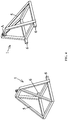
- FIG. 6 is a schematic diagram of a swing mechanism in the disclosure.
- FIG. 7 is an exploded view of a swing mechanism in the disclosure.
- FIG. 8 is an enlarged view of part B in FIG. 6 in the disclosure.
- FIG. 9 is a schematic diagram of a rotating mechanism in the disclosure.
- 1 supporting mechanism
- 2 swinging mechanism
- 3 rotating mechanism
- 4 test model
- 5 support frame
- 6 base frame
- 7 bracket
- 7 a locating pin
- 7 b groove
- 8 bracket support
- 9 suspension pin
- 10 first swing frame
- 10 a first sleeve rod
- 11 second swing frame
- 11 a second sleeve rod
- 12 rotary table base
- 12 a third sleeve rod
- 12 b axle hole
- 13 fastening bolt
- 14 spring pin
- 15 , rotary table
- 15 a radial supporting rod
- 16 rotating shaft
- 17 through hole
- 18 angle sensor
- 19 pressure sensor
- 20 signal acquisition unit.
- FIG. 1 , FIG. 2 , FIG. 3 illustrate a device for measuring and adjusting the inertia of a test model of an offshore structure.
- the device comprises supporting mechanisms 1 , a swinging mechanism 2 , a rotating mechanism 3 and a measuring instrument.
- the supporting mechanisms 1 are symmetrically disposed at two ends of the swing mechanism.
- the swinging mechanism 2 is connected to the supporting mechanisms 1 through suspension pins 9 .
- the swinging mechanism can swing freely on the supporting mechanisms.
- the arrangement of the suspension pins reduces the swing damping and improves the measurement accuracy.
- the rotating mechanism 3 comprises a rotating shaft 16 , and the rotating mechanism is connected to the rotary table base 12 of the swinging mechanism 2 through the rotating shaft 16 .
- a rotary table 15 is deposed on the rotary table base 12 .
- a test model 4 is placed on the rotary table 15 and can rotate around the axis.
- the angle sensor 18 and the pressure sensor 19 of the measuring instrument are connected to a signal acquisition unit 20 , so that data can be processed conveniently and quickly.
- FIG. 4 and FIG. 5 illustrate structure diagrams of the supporting mechanisms 1 .
- the supporting mechanisms 1 are symmetrically disposed at two ends of the swing mechanism, and each supporting mechanism comprises a support frame 5 , a base frame 6 , a bracket 7 and a bracket support 8 .
- the support frame 5 and the base frame 6 employ square tubes.
- the support frame is disposed on the base frame 6 .
- the bracket support 8 is disposed on the support frame 5 ; the bracket 7 is slidably disposed on the bracket support 8 via four locating pins 7 a ; and a groove 7 b is disposed on the top surface of the bracket.
- the pressure sensor 19 is disposed between the bracket and the bracket support to measure the weight of the test model 4 .
- the suspension pin 9 is inserted in the groove 7 b of the bracket 7 of the support frame to connect the supporting mechanisms and the swing mechanism.
- FIG. 6 , FIG. 7 , and FIG. 8 illustrate schematic diagrams of the swinging mechanism 2 .
- the swinging mechanism 2 is of a hollow square tube structure and mainly comprises a first swing frame 10 , a second swing frame 11 and a rotary table base 12 disposed between the first swing frame and the second swing frame.
- the angle sensor 18 is fixed on the swinging mechanism and can move together with the swinging mechanism, and then the angular variation of the swinging mechanism 2 along with time can be measured.
- the first swing frame 10 and the second swing frame 11 each comprises a vertically disposed triangle member, and the suspension pin 9 is disposed at a vertex of the triangle member as connecting points of the supporting mechanisms 1 and the swing mechanism 2 .
- the first swing frame comprises a first sleeve rod 10 a
- the second swing frame comprises a second sleeve rod 11 a
- the first sleeve rod 10 a is slightly thicker than the second sleeve rod 11 a
- the rotary table base 12 is centrosymmetric, and comprises an axle hole 12 b , a third sleeve rod 12 a , a side wall, and a spring pin 14 disposed on the side wall; the first sleeve rod 10 a and the second sleeve rod 11 a are inserted in the third sleeve rod 12 a , and then are locked using fastening bolts.
- the length of the swinging mechanism 2 is adjustable.
- FIG. 9 illustrates the rotating mechanism 3 .
- the rotating mechanism 3 comprises a rotary table 15 .
- the rotary table 15 is wheel-shaped and comprises a rotating shaft 16 and a plurality of radial supporting rods 15 a .
- the radial supporting rods 15 a are arranged inside the rotary table at intervals of 30 degrees.
- the rotating shaft 16 is arranged at the lower part of the center of the rotary table 15 , can be inserted in the axle hole 12 b in the rotary table base 12 .
- the side wall of each radial supporting rod 15 a is provided with a protrusion, and the protrusion comprises a through hole 17 .
- the spring pin 14 of the rotary table base 12 is inserted in the through hole 17 to fix the rotary table base 12 and the rotary table 15 .
Landscapes
- Physics & Mathematics (AREA)
- General Physics & Mathematics (AREA)
- Engineering & Computer Science (AREA)
- Mathematical Physics (AREA)
- Theoretical Computer Science (AREA)
- Aviation & Aerospace Engineering (AREA)
- Testing Of Balance (AREA)
- Force Measurement Appropriate To Specific Purposes (AREA)
Applications Claiming Priority (4)
| Application Number | Priority Date | Filing Date | Title |
|---|---|---|---|
| CN201610306285 | 2016-05-11 | ||
| CN201610306285.0 | 2016-05-11 | ||
| CN201610306285.0A CN105784276B (zh) | 2016-05-11 | 2016-05-11 | 海工结构物试验模型多轴向惯量自动测量与调节装置及其使用方法 |
| PCT/CN2017/078084 WO2017193713A1 (fr) | 2016-05-11 | 2017-03-24 | Dispositif de mesure et de réglage automatiques d'inertie de modèle de test de structure marine selon plusieurs axes, et son procédé d'utilisation |
Related Parent Applications (1)
| Application Number | Title | Priority Date | Filing Date |
|---|---|---|---|
| PCT/CN2017/078084 Continuation-In-Part WO2017193713A1 (fr) | 2016-05-11 | 2017-03-24 | Dispositif de mesure et de réglage automatiques d'inertie de modèle de test de structure marine selon plusieurs axes, et son procédé d'utilisation |
Publications (2)
| Publication Number | Publication Date |
|---|---|
| US20190033157A1 US20190033157A1 (en) | 2019-01-31 |
| US10801909B2 true US10801909B2 (en) | 2020-10-13 |
Family
ID=56401828
Family Applications (1)
| Application Number | Title | Priority Date | Filing Date |
|---|---|---|---|
| US16/147,866 Expired - Fee Related US10801909B2 (en) | 2016-05-11 | 2018-09-30 | Device for measuring and adjusting inertia of test model of offshore structure and method for using the same |
Country Status (3)
| Country | Link |
|---|---|
| US (1) | US10801909B2 (fr) |
| CN (1) | CN105784276B (fr) |
| WO (1) | WO2017193713A1 (fr) |
Cited By (2)
| Publication number | Priority date | Publication date | Assignee | Title |
|---|---|---|---|---|
| US11333568B2 (en) * | 2013-05-14 | 2022-05-17 | Resonic Gmbh | Gravity pendulum, adapter and holder |
| US20240151605A1 (en) * | 2023-01-13 | 2024-05-09 | Beijing Aerospace Institute For Metrology And Measurement Technology | Device for measuring length and center of mass of conical workpiece |
Families Citing this family (16)
| Publication number | Priority date | Publication date | Assignee | Title |
|---|---|---|---|---|
| CN105784276B (zh) * | 2016-05-11 | 2017-12-26 | 大连理工大学 | 海工结构物试验模型多轴向惯量自动测量与调节装置及其使用方法 |
| CN107450059B (zh) * | 2017-07-24 | 2019-05-24 | 长乐晶尚设计有限公司 | 一种便于工程测量的转动设备 |
| CN108645566B (zh) * | 2018-08-16 | 2023-11-10 | 孝感市宝龙电子有限公司 | 一种弹箭质量质心转动惯量测试台 |
| CN109916557A (zh) * | 2019-04-09 | 2019-06-21 | 清华大学深圳研究生院 | 一种结构测量装置 |
| CN110046429B (zh) * | 2019-04-16 | 2024-03-19 | 西安长庆科技工程有限责任公司 | 一种用于一体化装置的吊架及其设计方法 |
| CN110319975B (zh) * | 2019-07-19 | 2022-04-15 | 上海冠驰汽车安全技术有限公司 | 一种质心测量装置的质心计算方法 |
| CN111307371B (zh) * | 2020-03-25 | 2021-12-28 | 上海海迅机电工程有限公司 | 一种用于船舶重心测量方法 |
| CN111811733B (zh) * | 2020-07-01 | 2022-06-28 | 上海航天精密机械研究所 | 一种测量偏心回转体轴向转动惯量的通用装置 |
| CN111765955B (zh) * | 2020-07-09 | 2021-10-08 | 湖南润天智科机械制造有限公司 | 一种新型的物料计量装置 |
| CN112649150B (zh) * | 2021-01-26 | 2025-02-11 | 郑州机械研究所有限公司 | 一种通用型质量特性参数测量装置 |
| CN113772115B (zh) * | 2021-11-12 | 2022-02-11 | 中国空气动力研究与发展中心低速空气动力研究所 | 一种直升机后置式平尾舵面偏角控制的设计方法 |
| CN115352591A (zh) * | 2022-09-21 | 2022-11-18 | 中国电力工程顾问集团东北电力设计院有限公司 | 一种半潜式浮式基础模型试验辅助装置及其使用方法 |
| CN115962888B (zh) * | 2023-01-30 | 2025-12-23 | 北京理工大学 | 一种测量精密组件微小惯量积的高精度装置 |
| CN118533464B (zh) * | 2024-07-26 | 2024-10-18 | 济宁市晨新医疗器械有限公司 | 一种电动手术台台面摆动量测试装置及测试方法 |
| CN119245931A (zh) * | 2024-10-09 | 2025-01-03 | 武汉船用电力推进装置研究所(中国船舶集团有限公司第七一二研究所) | 一种异形电池组重心测量装置以及方法 |
| CN119437618B (zh) * | 2024-10-15 | 2025-12-30 | 中国直升机设计研究所 | 一种跌落试验配平调节装置和方法 |
Citations (22)
| Publication number | Priority date | Publication date | Assignee | Title |
|---|---|---|---|---|
| US3388589A (en) * | 1964-12-17 | 1968-06-18 | Army Usa | Method and apparatus for determining the center of gravity |
| US3693413A (en) * | 1971-02-02 | 1972-09-26 | Richard Studley Boynton | Moment of inertia measuring instrument |
| US3869007A (en) * | 1972-11-13 | 1975-03-04 | Bojors Ab | Weighing table particularly for a roller conveyor |
| US4991437A (en) * | 1988-11-30 | 1991-02-12 | Hanchett Raymond L | Airfoil balancer |
| US5038604A (en) * | 1987-08-05 | 1991-08-13 | Aerospatiale Societe Nationale Industrielle | Apparatus for measuring the mass-related characteristics of a body and its application to the measurement of the characteristics of a dry satellite |
| US5081865A (en) * | 1990-06-29 | 1992-01-21 | The United States Of America As Represented By The Secretary Of The Air Force | Center of gravity locating method |
| US5177998A (en) * | 1988-02-04 | 1993-01-12 | The United States Of America As Represented By The Secretary Of Transportation | Center of gravity and moments of inertia measurement device |
| US6137065A (en) * | 1993-04-23 | 2000-10-24 | Zefira; Uri | Level weighing device |
| US7278295B2 (en) * | 2002-05-31 | 2007-10-09 | Politecnico Di Milano | Device for measuring the inertia tensor of a rigid body |
| US7855343B2 (en) * | 2005-12-01 | 2010-12-21 | Ishida Co., Ltd. | Measuring device having hopper with adjustable shape and adjustable opening degrees |
| US8505373B2 (en) * | 2006-10-06 | 2013-08-13 | Rheinisch-Westfaelische Technische Hochschule | Device and method for determining the intertial parameters of a body |
| US8701472B2 (en) * | 2007-04-10 | 2014-04-22 | Fraunhofer-Gesellschaft Zur Foerderung Der Angewandten Forschung E.V. | Method for determining centers of mass for large structures |
| US9188503B2 (en) * | 2010-07-08 | 2015-11-17 | Tokyo Institute Of Technology | Rigid body characteristic identification system and rigid body characteristic identification method |
| US9417151B2 (en) * | 2011-11-28 | 2016-08-16 | The Boeing Company | Center of gravity determination |
| US9714880B2 (en) * | 2014-11-18 | 2017-07-25 | Korea Institute Of Ocean Science And Technology | Inertia test apparatus for model ship |
| US9846100B2 (en) * | 2013-05-14 | 2017-12-19 | Resonic Gmbh | Device and method for determining inertia properties of an object |
| US9933324B2 (en) * | 2014-11-18 | 2018-04-03 | The Trinko Group, LLC | System for field measurement of center of gravity |
| US9952249B2 (en) * | 2013-04-25 | 2018-04-24 | Okuma Corporation | Inertia estimating method and inertia estimation apparatus of position control apparatus |
| US10040514B1 (en) * | 2017-07-05 | 2018-08-07 | Dalian University Of Technology | Testing device for model of floating gate and method of using the same |
| US10197468B2 (en) * | 2011-05-31 | 2019-02-05 | Resonic Gmbh | System and method for determining inertia properties of a rigid body |
| US10337943B2 (en) * | 2014-11-12 | 2019-07-02 | Andreas Hettich Gmbh & Co. Kg | Centrifuge and method for sensing imbalances in the centrifuge |
| US10539479B2 (en) * | 2013-05-14 | 2020-01-21 | Resonic Gmbh | Gravity pendulum, adapter and holder |
Family Cites Families (7)
| Publication number | Priority date | Publication date | Assignee | Title |
|---|---|---|---|---|
| CN201331416Y (zh) * | 2008-11-26 | 2009-10-21 | 中国第一汽车集团公司 | 轿车动力总成质心、转动惯量测量装置 |
| CN101561335A (zh) * | 2009-05-27 | 2009-10-21 | 郑州机械研究所 | 用于实现质量、三维质心和三维转动惯量的测量机构 |
| CN201532283U (zh) * | 2009-05-27 | 2010-07-21 | 郑州机械研究所 | 用于实现质量、三维质心和三维转动惯量的测量机构 |
| CN201955198U (zh) * | 2010-12-25 | 2011-08-31 | 中国第一汽车集团公司 | 小型汽车零部件质心转动惯量测量装置 |
| CN104180940B (zh) * | 2014-09-03 | 2016-08-17 | 郑州机械研究所 | 用于测量物体质心、转动惯量和惯性积的测量装置 |
| CN105784276B (zh) * | 2016-05-11 | 2017-12-26 | 大连理工大学 | 海工结构物试验模型多轴向惯量自动测量与调节装置及其使用方法 |
| CN205655960U (zh) * | 2016-05-11 | 2016-10-19 | 大连理工大学 | 一种海工结构物试验模型多轴向惯量自动测量与调节装置 |
-
2016
- 2016-05-11 CN CN201610306285.0A patent/CN105784276B/zh not_active Expired - Fee Related
-
2017
- 2017-03-24 WO PCT/CN2017/078084 patent/WO2017193713A1/fr not_active Ceased
-
2018
- 2018-09-30 US US16/147,866 patent/US10801909B2/en not_active Expired - Fee Related
Patent Citations (22)
| Publication number | Priority date | Publication date | Assignee | Title |
|---|---|---|---|---|
| US3388589A (en) * | 1964-12-17 | 1968-06-18 | Army Usa | Method and apparatus for determining the center of gravity |
| US3693413A (en) * | 1971-02-02 | 1972-09-26 | Richard Studley Boynton | Moment of inertia measuring instrument |
| US3869007A (en) * | 1972-11-13 | 1975-03-04 | Bojors Ab | Weighing table particularly for a roller conveyor |
| US5038604A (en) * | 1987-08-05 | 1991-08-13 | Aerospatiale Societe Nationale Industrielle | Apparatus for measuring the mass-related characteristics of a body and its application to the measurement of the characteristics of a dry satellite |
| US5177998A (en) * | 1988-02-04 | 1993-01-12 | The United States Of America As Represented By The Secretary Of Transportation | Center of gravity and moments of inertia measurement device |
| US4991437A (en) * | 1988-11-30 | 1991-02-12 | Hanchett Raymond L | Airfoil balancer |
| US5081865A (en) * | 1990-06-29 | 1992-01-21 | The United States Of America As Represented By The Secretary Of The Air Force | Center of gravity locating method |
| US6137065A (en) * | 1993-04-23 | 2000-10-24 | Zefira; Uri | Level weighing device |
| US7278295B2 (en) * | 2002-05-31 | 2007-10-09 | Politecnico Di Milano | Device for measuring the inertia tensor of a rigid body |
| US7855343B2 (en) * | 2005-12-01 | 2010-12-21 | Ishida Co., Ltd. | Measuring device having hopper with adjustable shape and adjustable opening degrees |
| US8505373B2 (en) * | 2006-10-06 | 2013-08-13 | Rheinisch-Westfaelische Technische Hochschule | Device and method for determining the intertial parameters of a body |
| US8701472B2 (en) * | 2007-04-10 | 2014-04-22 | Fraunhofer-Gesellschaft Zur Foerderung Der Angewandten Forschung E.V. | Method for determining centers of mass for large structures |
| US9188503B2 (en) * | 2010-07-08 | 2015-11-17 | Tokyo Institute Of Technology | Rigid body characteristic identification system and rigid body characteristic identification method |
| US10197468B2 (en) * | 2011-05-31 | 2019-02-05 | Resonic Gmbh | System and method for determining inertia properties of a rigid body |
| US9417151B2 (en) * | 2011-11-28 | 2016-08-16 | The Boeing Company | Center of gravity determination |
| US9952249B2 (en) * | 2013-04-25 | 2018-04-24 | Okuma Corporation | Inertia estimating method and inertia estimation apparatus of position control apparatus |
| US9846100B2 (en) * | 2013-05-14 | 2017-12-19 | Resonic Gmbh | Device and method for determining inertia properties of an object |
| US10539479B2 (en) * | 2013-05-14 | 2020-01-21 | Resonic Gmbh | Gravity pendulum, adapter and holder |
| US10337943B2 (en) * | 2014-11-12 | 2019-07-02 | Andreas Hettich Gmbh & Co. Kg | Centrifuge and method for sensing imbalances in the centrifuge |
| US9714880B2 (en) * | 2014-11-18 | 2017-07-25 | Korea Institute Of Ocean Science And Technology | Inertia test apparatus for model ship |
| US9933324B2 (en) * | 2014-11-18 | 2018-04-03 | The Trinko Group, LLC | System for field measurement of center of gravity |
| US10040514B1 (en) * | 2017-07-05 | 2018-08-07 | Dalian University Of Technology | Testing device for model of floating gate and method of using the same |
Cited By (3)
| Publication number | Priority date | Publication date | Assignee | Title |
|---|---|---|---|---|
| US11333568B2 (en) * | 2013-05-14 | 2022-05-17 | Resonic Gmbh | Gravity pendulum, adapter and holder |
| US20240151605A1 (en) * | 2023-01-13 | 2024-05-09 | Beijing Aerospace Institute For Metrology And Measurement Technology | Device for measuring length and center of mass of conical workpiece |
| US11988572B1 (en) * | 2023-01-13 | 2024-05-21 | Beijing Aerospace Institute For Metrology And Measurement Technology | Device for measuring length and center of mass of conical workpiece |
Also Published As
| Publication number | Publication date |
|---|---|
| CN105784276B (zh) | 2017-12-26 |
| CN105784276A (zh) | 2016-07-20 |
| US20190033157A1 (en) | 2019-01-31 |
| WO2017193713A1 (fr) | 2017-11-16 |
Similar Documents
| Publication | Publication Date | Title |
|---|---|---|
| US20190033157A1 (en) | Device for measuring and adjusting inertia of test model of offshore structure and method for using the same | |
| CN104977148A (zh) | 风洞试验段迎角机构旋转中心的检测装置及方法 | |
| CN109916706B (zh) | 一种混凝土固支构件抗爆性能的试验装置 | |
| CN106842222A (zh) | 一种矿用深孔激光测量仪 | |
| CN106950028A (zh) | 用于风洞试验的支撑组件 | |
| CN108020199B (zh) | 裂缝形变监测仪 | |
| CN216621681U (zh) | 一种新型动导数弹性铰链校准装置 | |
| CN202119369U (zh) | 桩孔纵深直径简易测量装置 | |
| CN102704915A (zh) | 一种随钻测斜仪的校验台及校验方法 | |
| CN202119407U (zh) | 一种适于校准齿轮测量中心的双球渐开线样板 | |
| CN206557382U (zh) | 一种矿用深孔激光测量仪 | |
| CN110608755B (zh) | 用于惯性导航设备的升沉测量性能检测装置及方法 | |
| CN106226042A (zh) | 空间光学遥感器碳纤维结构稳定性的自动测试系统及方法 | |
| CN115979580B (zh) | 一种双天平测量系统的工装校准结构及使用方法 | |
| CN113983916B (zh) | 隧洞变形测试装置 | |
| CN213714618U (zh) | 一种工作测力计综合检测装置 | |
| CN110160736A (zh) | 一种耦合弹性模态非定常气动力测量装置及方法 | |
| CN109974557A (zh) | 可旋转综合测量仪及测量方法 | |
| CN103575258A (zh) | 钢缆中心测定觇标架 | |
| CN211234964U (zh) | 一种发动机推力测量动架及其推力测量台架 | |
| CN209927394U (zh) | 高精度波纹管环刚度测试装置 | |
| CN210802909U (zh) | 一种发动机推力测量台架 | |
| CN110319760A (zh) | 岩石变形引伸计标定装置及标定方法 | |
| CN205655960U (zh) | 一种海工结构物试验模型多轴向惯量自动测量与调节装置 | |
| CN109737015B (zh) | 水平轴复合材料风力机叶片力学性能实验测试装置 |
Legal Events
| Date | Code | Title | Description |
|---|---|---|---|
| AS | Assignment |
Owner name: DALIAN UNIVERSITY OF TECHNOLOGY, CHINA Free format text: ASSIGNMENT OF ASSIGNORS INTEREST;ASSIGNORS:LIN, YAN;JIANG, XIAONING;SIGNING DATES FROM 20180103 TO 20180104;REEL/FRAME:047014/0448 |
|
| FEPP | Fee payment procedure |
Free format text: ENTITY STATUS SET TO UNDISCOUNTED (ORIGINAL EVENT CODE: BIG.); ENTITY STATUS OF PATENT OWNER: SMALL ENTITY |
|
| FEPP | Fee payment procedure |
Free format text: ENTITY STATUS SET TO SMALL (ORIGINAL EVENT CODE: SMAL); ENTITY STATUS OF PATENT OWNER: SMALL ENTITY |
|
| STPP | Information on status: patent application and granting procedure in general |
Free format text: APPLICATION DISPATCHED FROM PREEXAM, NOT YET DOCKETED |
|
| STPP | Information on status: patent application and granting procedure in general |
Free format text: DOCKETED NEW CASE - READY FOR EXAMINATION |
|
| STPP | Information on status: patent application and granting procedure in general |
Free format text: NON FINAL ACTION MAILED |
|
| STPP | Information on status: patent application and granting procedure in general |
Free format text: NOTICE OF ALLOWANCE MAILED -- APPLICATION RECEIVED IN OFFICE OF PUBLICATIONS |
|
| STPP | Information on status: patent application and granting procedure in general |
Free format text: PUBLICATIONS -- ISSUE FEE PAYMENT RECEIVED |
|
| STCF | Information on status: patent grant |
Free format text: PATENTED CASE |
|
| FEPP | Fee payment procedure |
Free format text: MAINTENANCE FEE REMINDER MAILED (ORIGINAL EVENT CODE: REM.); ENTITY STATUS OF PATENT OWNER: SMALL ENTITY |
|
| LAPS | Lapse for failure to pay maintenance fees |
Free format text: PATENT EXPIRED FOR FAILURE TO PAY MAINTENANCE FEES (ORIGINAL EVENT CODE: EXP.); ENTITY STATUS OF PATENT OWNER: SMALL ENTITY |
|
| STCH | Information on status: patent discontinuation |
Free format text: PATENT EXPIRED DUE TO NONPAYMENT OF MAINTENANCE FEES UNDER 37 CFR 1.362 |
|
| FP | Lapsed due to failure to pay maintenance fee |
Effective date: 20241013 |