US1080596A - Folding hat-box. - Google Patents
Folding hat-box. Download PDFInfo
- Publication number
- US1080596A US1080596A US70902112A US1912709021A US1080596A US 1080596 A US1080596 A US 1080596A US 70902112 A US70902112 A US 70902112A US 1912709021 A US1912709021 A US 1912709021A US 1080596 A US1080596 A US 1080596A
- Authority
- US
- United States
- Prior art keywords
- box
- flap
- walls
- folded
- hat
- Prior art date
- Legal status (The legal status is an assumption and is not a legal conclusion. Google has not performed a legal analysis and makes no representation as to the accuracy of the status listed.)
- Expired - Lifetime
Links
- 238000010276 construction Methods 0.000 description 3
- 239000004744 fabric Substances 0.000 description 2
- 239000003292 glue Substances 0.000 description 1
- 239000000463 material Substances 0.000 description 1
Images


Classifications
-
- B—PERFORMING OPERATIONS; TRANSPORTING
- B65—CONVEYING; PACKING; STORING; HANDLING THIN OR FILAMENTARY MATERIAL
- B65D—CONTAINERS FOR STORAGE OR TRANSPORT OF ARTICLES OR MATERIALS, e.g. BAGS, BARRELS, BOTTLES, BOXES, CANS, CARTONS, CRATES, DRUMS, JARS, TANKS, HOPPERS, FORWARDING CONTAINERS; ACCESSORIES, CLOSURES, OR FITTINGS THEREFOR; PACKAGING ELEMENTS; PACKAGES
- B65D5/00—Rigid or semi-rigid containers of polygonal cross-section, e.g. boxes, cartons or trays, formed by folding or erecting one or more blanks made of paper
- B65D5/36—Rigid or semi-rigid containers of polygonal cross-section, e.g. boxes, cartons or trays, formed by folding or erecting one or more blanks made of paper specially constructed to allow collapsing and re-erecting without disengagement of side or bottom connections
Definitions
- This invention relates to folding hat boxes, especially used by wholesale and retail dealers in ladies hats.
- the object of the invention is to provide a box which is, when ready for use, of suflicient size to contain a large hat and which will, on being folded, assume a very compact form for ready storage and shipment.
- the invention consists in a novel form of box which can be easily and cheaply made and operated, which is satisfactory in oper-.
- the invention further consists in details of construction which will be more fully set forth in the specification and claim.
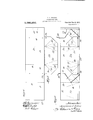
- Figure 1 is a perspective View of a hat box illustrating this invention in its preferred form, said box being in what will be hereafter referred to as the normal or usable position.
- Fig. 2 illustrates the exterior of said box in partially folded posi- 30 tion, and Fig. 3 shows it in substantially .completely folded position.
- Fig. 4 illustrates the four side walls of the box developed or laid out flat.
- Fig. 5 shows one half of the member forming the bottom of the 36 box and its connections to its adjacent side wall of the box separated from said side wall and flattened out.
- Fig. 6 is a developed view of the interior of the box showing all parts which are attached thereto in the position which they occupy in Fig. 7.
- Fig. 6 is a developed view of the interior of the box showing all parts which are attached thereto in the position which they occupy in Fig. 7.
- Fig. 1 is a perspective View of a hat box illustrating this invention in its preferred form, said box being in what will be hereafter
- Fig. 7 is a plan viewlooking into the box with the bottom members folded up into contact with the side walls in the position ready to be moved to the position of Fig. 2 and thence to that of Fig. 3.
- Fig. 8 is a corresponding view showing the interior of the box when the interior parts of Fig. 7 have been folded so that the box is in normal position ready for use.
- Fig. 9 is a sectional detail view on the line 9 of Fig. 8.
- the box is made rectangular, preferably, but not at all necessarily square, with four walls 11, 12, 13, and 14, the first and last being connected along the corner 21 by a pasted flap or splice 16, in the ordinary manner. These four walls may be formed from one piece of material scored in the lines 18, 19, and 20 to form the corners of the box, but the various walls may be separate and secured together by hinges,like flaps 16 without in any way departing from this invention.
- the box is closed by an ordinary cover 22. Whenever the horizontal and vertical dimensions of the largest sized wall of the box do not exceed the dimensions of this cover 22 the entire device, after being folded to the position of Fig. 3, may be placed in and packed within a cover 22, if desired.
- walls 11 and 13 will be referred to as side walls and walls 12 and 14 as end Walls Pivoted to each of the side walls 11 and 13 by means of a suitable hinge, such as the cloth edge 24, is a flap member 26, shown in developed form in Fig. 5, having end portions 28 preferably of a length greater than one half the width of the adjacent end walls 12 and 14 secured to said respective walls 12 and 14 by that portion of the cloth hinge member 24 which is attached thereto.
- a flap 27 is secured to end wall 11.
- Each of these flaps is scored so as to be foldable along the lines 30, 31, 32, and 33. Lines 32 are perpendicular to the hinge edges of the flaps and in the positions of both Figs.
- Score lines 30 lie in substantially the planes of the respective adjacent end walls.
- Score lines 30 are located on the end portions of the flap 26 ninety degrees from lines 32.
- Score lines 31 are midway between lines 32 and 33 or twenty-two and one-balf degrees from each wall.
- Score lines 33 are twenty-two and one-half degrees from lines 32, buttoward the center of the flap 26.
- Each flap 26 is of a width greater than one-half the width of the end walls of the box which are adjacent to the side wall on which the flap is attached; that is to say,
- a pair of strings 36 are provided rigidly secured at the opposite end walls 12 and 14 of the box at the points 38, from which these strings thence extend outside of the side Wall of the box down under the bottom of the side wall and thence loosely through the holes in the adjacent bottom flap 27, thence up the inside of the box to the holes 42, thence to the outside of the box and thenceover the cover 22, where they may be tied in the knot 44.
- a collapsible box having side and end walls hinged together, a pair of oppositely disposed flaps hinged to the opposite side walls and adapted to form the bottom wall of the box, said flaps having hinged end portions secured by hinge connections to the inner surface of the end walls at an angle of substantially forty-five degrees with the plane of the bottom edge of said walls, whereby said flaps will be held against outward movement but free to be moved in- Wardly against the side walls to permit the box to be collapsed and folded, substantially as described.
Landscapes
- Engineering & Computer Science (AREA)
- Mechanical Engineering (AREA)
- Cartons (AREA)
Description
A. I. SELCER.
FOLDING HAT BOX.
APPLICATION FILED JULY 12,1912.
Patented Dec. 9, 1913.
3 SHEETS-SHEET 1.
A. I. SELGER.
FOLDING HAT BOX.
APPLICATION FILED JULY 12, 1912.
1,080,596. Patented Dec.9,1913.
3 SHEETS-SHEET 2.
mwmw A. I. SELCBR.
FOLDING HAT BOX.
APPLICATION FILED JULY 12, 1912.
Patented Dec. 9, 1913.
3 8HEETSBHEET 3.
UNITED STATES PATENT oFFIoE.
ABRAHAM I. SELCER, OF CHICAGO, ILLINOIS, ASSIGNOR TO GAGE HAT WORKS, O]?
i CHICAGO, ILLINOIS, A ,CORPORATION OF ILLINOIS.
FOLDING- HAT-BOX.
Specification of Letters Patent.
Patented Dec. 9, 1913.
Application filed July 12, 1912. Serial No. 709,021.
To all whom it may concern:
Be it known that I, ABRAHAM I. SnLcER,
a citizen of the United States, residing at Chicago, in the county of Cook and State of Illinois, have invented a certain new and useful Improvement in Folding Hat-Boxes, of which the following is a specification.
This invention relates to folding hat boxes, especially used by wholesale and retail dealers in ladies hats.
The object of the invention is to provide a box which is, when ready for use, of suflicient size to contain a large hat and which will, on being folded, assume a very compact form for ready storage and shipment.
The invention consists in a novel form of box which can be easily and cheaply made and operated, which is satisfactory in oper-.
ation and not readily liable to get out of order, which attains the foregoing objects.
The invention further consists in details of construction which will be more fully set forth in the specification and claim.
Figure 1 is a perspective View of a hat box illustrating this invention in its preferred form, said box being in what will be hereafter referred to as the normal or usable position. Fig. 2 illustrates the exterior of said box in partially folded posi- 30 tion, and Fig. 3 shows it in substantially .completely folded position. Fig. 4 illustrates the four side walls of the box developed or laid out flat. Fig. 5 shows one half of the member forming the bottom of the 36 box and its connections to its adjacent side wall of the box separated from said side wall and flattened out. Fig. 6 is a developed view of the interior of the box showing all parts which are attached thereto in the position which they occupy in Fig. 7. Fig. 7 is a plan viewlooking into the box with the bottom members folded up into contact with the side walls in the position ready to be moved to the position of Fig. 2 and thence to that of Fig. 3. Fig. 8 is a corresponding view showing the interior of the box when the interior parts of Fig. 7 have been folded so that the box is in normal position ready for use. Fig. 9 is a sectional detail view on the line 9 of Fig. 8.
In order to clearly illustrate the various features of the structure the foldable parts shown in Figs. 7, 8, and 9, are somewhat enlarged and distorted from their natural 55 positions.
The box is made rectangular, preferably, but not at all necessarily square, with four walls 11, 12, 13, and 14, the first and last being connected along the corner 21 by a pasted flap or splice 16, in the ordinary manner. These four walls may be formed from one piece of material scored in the lines 18, 19, and 20 to form the corners of the box, but the various walls may be separate and secured together by hinges,like flaps 16 without in any way departing from this invention. The box is closed by an ordinary cover 22. Whenever the horizontal and vertical dimensions of the largest sized wall of the box do not exceed the dimensions of this cover 22 the entire device, after being folded to the position of Fig. 3, may be placed in and packed within a cover 22, if desired. Merely for convenience, walls 11 and 13 will be referred to as side walls and walls 12 and 14 as end Walls Pivoted to each of the side walls 11 and 13 by means of a suitable hinge, such as the cloth edge 24, is a flap member 26, shown in developed form in Fig. 5, having end portions 28 preferably of a length greater than one half the width of the adjacent end walls 12 and 14 secured to said respective walls 12 and 14 by that portion of the cloth hinge member 24 which is attached thereto. Similarly secured to end wall 11 is a corresponding flap 27. Each of these flaps is scored so as to be foldable along the lines 30, 31, 32, and 33. Lines 32 are perpendicular to the hinge edges of the flaps and in the positions of both Figs. 7 and 8, lie in substantially the planes of the respective adjacent end walls. Score lines 30 are located on the end portions of the flap 26 ninety degrees from lines 32. Score lines 31 are midway between lines 32 and 33 or twenty-two and one-balf degrees from each wall. Score lines 33 are twenty-two and one-half degrees from lines 32, buttoward the center of the flap 26. Each flap 26 is of a width greater than one-half the width of the end walls of the box which are adjacent to the side wall on which the flap is attached; that is to say,
13 will, when folded to the position of Fig.
8, overlap at the center, thus forming a proper bottom for the box. The result of the construction just described is that when each flap 26 is folded from the position of Figs. 4 and 5 to the position of Fig. 6, and the portions of the end 28 of the flap which are outside of and beyond the score lines 30 are secured to the respective walls 12 and 14 by glue or the like, and then the wall 11 is attached to the wall 14 by the flap 16, the
parts will all be in the position shown in Fig. 7, with the score orhinge line 30 mak-- 'In order, however, to make it even more satisfactory in this regard a pair of strings 36 are provided rigidly secured at the opposite end walls 12 and 14 of the box at the points 38, from which these strings thence extend outside of the side Wall of the box down under the bottom of the side wall and thence loosely through the holes in the adjacent bottom flap 27, thence up the inside of the box to the holes 42, thence to the outside of the box and thenceover the cover 22, where they may be tied in the knot 44. Any strain placed upon this portion of the strings 36 which are, as just described, outside the box, is communicated to the bottom of the box, as a pull tending to draw the bottom folded flap 27 taut across the bottom of the box opening and as this string construction thus reinforces the lower flap 27 the upper flap 26 is correspondingly supported because it rests upon flap 27.
Assuming that the box has been folded up, the person desiring to use the same rests it in the position of Fig.- 3, then folds it to the position of Fig. 2, then opens itto the position of Fig. 7 then folds the flaps to the position of Fig. 8, then places the cover on the box, as shown in Fig. 1 and ties the knot 44. In folding up a used box the operation is reversed, passing successively through Figs. 1, 8, 7, 2, and 3.
The claims are A collapsible box having side and end walls hinged together, a pair of oppositely disposed flaps hinged to the opposite side walls and adapted to form the bottom wall of the box, said flaps having hinged end portions secured by hinge connections to the inner surface of the end walls at an angle of substantially forty-five degrees with the plane of the bottom edge of said walls, whereby said flaps will be held against outward movement but free to be moved in- Wardly against the side walls to permit the box to be collapsed and folded, substantially as described.
In witness whereof, I have hereunto subscribed my name in the presence of two witnesses.
ABRAHAM I. SELCER. Witnesses:
DWIGHT B. CHEEVER, BEN M. KOZENBLUC.
Priority Applications (1)
| Application Number | Priority Date | Filing Date | Title |
|---|---|---|---|
| US70902112A US1080596A (en) | 1912-07-12 | 1912-07-12 | Folding hat-box. |
Applications Claiming Priority (1)
| Application Number | Priority Date | Filing Date | Title |
|---|---|---|---|
| US70902112A US1080596A (en) | 1912-07-12 | 1912-07-12 | Folding hat-box. |
Publications (1)
| Publication Number | Publication Date |
|---|---|
| US1080596A true US1080596A (en) | 1913-12-09 |
Family
ID=3148830
Family Applications (1)
| Application Number | Title | Priority Date | Filing Date |
|---|---|---|---|
| US70902112A Expired - Lifetime US1080596A (en) | 1912-07-12 | 1912-07-12 | Folding hat-box. |
Country Status (1)
| Country | Link |
|---|---|
| US (1) | US1080596A (en) |
Cited By (2)
| Publication number | Priority date | Publication date | Assignee | Title |
|---|---|---|---|---|
| US6012842A (en) * | 1997-07-30 | 2000-01-11 | Openiano; Renato M. | Container convertible between a lidded shopping bag and a package variously suitable as gift wrap or for mailing |
| US20110114535A1 (en) * | 2005-11-14 | 2011-05-19 | 3M Innovative Properties Company | Folded boxes and methods of making the same |
-
1912
- 1912-07-12 US US70902112A patent/US1080596A/en not_active Expired - Lifetime
Cited By (2)
| Publication number | Priority date | Publication date | Assignee | Title |
|---|---|---|---|---|
| US6012842A (en) * | 1997-07-30 | 2000-01-11 | Openiano; Renato M. | Container convertible between a lidded shopping bag and a package variously suitable as gift wrap or for mailing |
| US20110114535A1 (en) * | 2005-11-14 | 2011-05-19 | 3M Innovative Properties Company | Folded boxes and methods of making the same |
Similar Documents
| Publication | Publication Date | Title |
|---|---|---|
| US443397A (en) | Millinery hat or bonnet box | |
| US396570A (en) | Paper box | |
| US728749A (en) | Collapsible box. | |
| US2292653A (en) | Package | |
| US1354928A (en) | Collapsible box | |
| US1532316A (en) | Collapsible box | |
| US700049A (en) | Folding box. | |
| US1563907A (en) | Folding box | |
| US3478949A (en) | One-piece collapsible book-type box | |
| US1080596A (en) | Folding hat-box. | |
| US1196320A (en) | Non-buckling folding box. | |
| US413784A (en) | Paper box | |
| US1054530A (en) | Foldable pasteboard receptacle. | |
| US414450A (en) | Folding box | |
| US1685016A (en) | blake | |
| US1063488A (en) | Collapsible box. | |
| US1135117A (en) | Box construction. | |
| US655019A (en) | Hat-box. | |
| US1114860A (en) | Foldable box. | |
| US1049910A (en) | Foldable blank box. | |
| US1103238A (en) | Folding box. | |
| US1132877A (en) | Folding paper box. | |
| US644857A (en) | Paper box. | |
| US717621A (en) | Paper bag. | |
| US692301A (en) | Folding paper box. |