US10826142B2 - Metal-air fuel cell - Google Patents
Metal-air fuel cell Download PDFInfo
- Publication number
- US10826142B2 US10826142B2 US15/923,256 US201815923256A US10826142B2 US 10826142 B2 US10826142 B2 US 10826142B2 US 201815923256 A US201815923256 A US 201815923256A US 10826142 B2 US10826142 B2 US 10826142B2
- Authority
- US
- United States
- Prior art keywords
- fuel cell
- anode
- electrolyte
- current collector
- metal
- Prior art date
- Legal status (The legal status is an assumption and is not a legal conclusion. Google has not performed a legal analysis and makes no representation as to the accuracy of the status listed.)
- Expired - Fee Related, expires
Links
- 239000000446 fuel Substances 0.000 title claims abstract description 121
- 239000002245 particle Substances 0.000 claims abstract description 75
- 239000003792 electrolyte Substances 0.000 claims abstract description 65
- 239000011701 zinc Substances 0.000 claims description 22
- 229910052751 metal Inorganic materials 0.000 claims description 20
- 239000002184 metal Substances 0.000 claims description 20
- KWYUFKZDYYNOTN-UHFFFAOYSA-M Potassium hydroxide Chemical group [OH-].[K+] KWYUFKZDYYNOTN-UHFFFAOYSA-M 0.000 claims description 19
- HCHKCACWOHOZIP-UHFFFAOYSA-N Zinc Chemical compound [Zn] HCHKCACWOHOZIP-UHFFFAOYSA-N 0.000 claims description 19
- 229910052725 zinc Inorganic materials 0.000 claims description 19
- 238000004891 communication Methods 0.000 claims description 5
- 239000012530 fluid Substances 0.000 claims description 5
- 239000002923 metal particle Substances 0.000 description 26
- 238000006243 chemical reaction Methods 0.000 description 12
- 238000005086 pumping Methods 0.000 description 7
- 238000013459 approach Methods 0.000 description 6
- QVGXLLKOCUKJST-UHFFFAOYSA-N atomic oxygen Chemical compound [O] QVGXLLKOCUKJST-UHFFFAOYSA-N 0.000 description 6
- 229910052760 oxygen Inorganic materials 0.000 description 6
- 239000001301 oxygen Substances 0.000 description 6
- 238000011144 upstream manufacturing Methods 0.000 description 6
- 230000015572 biosynthetic process Effects 0.000 description 5
- 238000000034 method Methods 0.000 description 5
- XEEYBQQBJWHFJM-UHFFFAOYSA-N Iron Chemical compound [Fe] XEEYBQQBJWHFJM-UHFFFAOYSA-N 0.000 description 4
- NWONKYPBYAMBJT-UHFFFAOYSA-L zinc sulfate Chemical compound [Zn+2].[O-]S([O-])(=O)=O NWONKYPBYAMBJT-UHFFFAOYSA-L 0.000 description 4
- ZLMJMSJWJFRBEC-UHFFFAOYSA-N Potassium Chemical compound [K] ZLMJMSJWJFRBEC-UHFFFAOYSA-N 0.000 description 3
- HEMHJVSKTPXQMS-UHFFFAOYSA-M Sodium hydroxide Chemical compound [OH-].[Na+] HEMHJVSKTPXQMS-UHFFFAOYSA-M 0.000 description 3
- 229910001854 alkali hydroxide Inorganic materials 0.000 description 3
- 150000008044 alkali metal hydroxides Chemical class 0.000 description 3
- 239000004020 conductor Substances 0.000 description 3
- 230000007423 decrease Effects 0.000 description 3
- 238000003411 electrode reaction Methods 0.000 description 3
- 229910052700 potassium Inorganic materials 0.000 description 3
- 239000011591 potassium Substances 0.000 description 3
- 230000009467 reduction Effects 0.000 description 3
- 239000002915 spent fuel radioactive waste Substances 0.000 description 3
- -1 zinc metals Chemical class 0.000 description 3
- FYYHWMGAXLPEAU-UHFFFAOYSA-N Magnesium Chemical compound [Mg] FYYHWMGAXLPEAU-UHFFFAOYSA-N 0.000 description 2
- PXHVJJICTQNCMI-UHFFFAOYSA-N Nickel Chemical compound [Ni] PXHVJJICTQNCMI-UHFFFAOYSA-N 0.000 description 2
- RTAQQCXQSZGOHL-UHFFFAOYSA-N Titanium Chemical compound [Ti] RTAQQCXQSZGOHL-UHFFFAOYSA-N 0.000 description 2
- 230000009471 action Effects 0.000 description 2
- 239000012670 alkaline solution Substances 0.000 description 2
- WYTGDNHDOZPMIW-RCBQFDQVSA-N alstonine Natural products C1=CC2=C3C=CC=CC3=NC2=C2N1C[C@H]1[C@H](C)OC=C(C(=O)OC)[C@H]1C2 WYTGDNHDOZPMIW-RCBQFDQVSA-N 0.000 description 2
- 230000000694 effects Effects 0.000 description 2
- XLYOFNOQVPJJNP-UHFFFAOYSA-M hydroxide Chemical compound [OH-] XLYOFNOQVPJJNP-UHFFFAOYSA-M 0.000 description 2
- 229910052742 iron Inorganic materials 0.000 description 2
- 229910052749 magnesium Inorganic materials 0.000 description 2
- 239000011777 magnesium Substances 0.000 description 2
- 230000007246 mechanism Effects 0.000 description 2
- 230000005012 migration Effects 0.000 description 2
- 238000013508 migration Methods 0.000 description 2
- 239000000047 product Substances 0.000 description 2
- 230000003746 surface roughness Effects 0.000 description 2
- 239000010936 titanium Substances 0.000 description 2
- 229910052719 titanium Inorganic materials 0.000 description 2
- 230000001052 transient effect Effects 0.000 description 2
- XLYOFNOQVPJJNP-UHFFFAOYSA-N water Chemical compound O XLYOFNOQVPJJNP-UHFFFAOYSA-N 0.000 description 2
- OYPRJOBELJOOCE-UHFFFAOYSA-N Calcium Chemical compound [Ca] OYPRJOBELJOOCE-UHFFFAOYSA-N 0.000 description 1
- OKTJSMMVPCPJKN-UHFFFAOYSA-N Carbon Chemical compound [C] OKTJSMMVPCPJKN-UHFFFAOYSA-N 0.000 description 1
- RYGMFSIKBFXOCR-UHFFFAOYSA-N Copper Chemical compound [Cu] RYGMFSIKBFXOCR-UHFFFAOYSA-N 0.000 description 1
- DGAQECJNVWCQMB-PUAWFVPOSA-M Ilexoside XXIX Chemical compound C[C@@H]1CC[C@@]2(CC[C@@]3(C(=CC[C@H]4[C@]3(CC[C@@H]5[C@@]4(CC[C@@H](C5(C)C)OS(=O)(=O)[O-])C)C)[C@@H]2[C@]1(C)O)C)C(=O)O[C@H]6[C@@H]([C@H]([C@@H]([C@H](O6)CO)O)O)O.[Na+] DGAQECJNVWCQMB-PUAWFVPOSA-M 0.000 description 1
- WHXSMMKQMYFTQS-UHFFFAOYSA-N Lithium Chemical compound [Li] WHXSMMKQMYFTQS-UHFFFAOYSA-N 0.000 description 1
- 229910052774 Proactinium Inorganic materials 0.000 description 1
- BQCADISMDOOEFD-UHFFFAOYSA-N Silver Chemical compound [Ag] BQCADISMDOOEFD-UHFFFAOYSA-N 0.000 description 1
- 230000006978 adaptation Effects 0.000 description 1
- 239000000956 alloy Substances 0.000 description 1
- 229910045601 alloy Inorganic materials 0.000 description 1
- 229910052782 aluminium Inorganic materials 0.000 description 1
- XAGFODPZIPBFFR-UHFFFAOYSA-N aluminium Chemical compound [Al] XAGFODPZIPBFFR-UHFFFAOYSA-N 0.000 description 1
- 230000003416 augmentation Effects 0.000 description 1
- 229910052790 beryllium Inorganic materials 0.000 description 1
- ATBAMAFKBVZNFJ-UHFFFAOYSA-N beryllium atom Chemical compound [Be] ATBAMAFKBVZNFJ-UHFFFAOYSA-N 0.000 description 1
- 229910052791 calcium Inorganic materials 0.000 description 1
- 239000011575 calcium Substances 0.000 description 1
- 229910052799 carbon Inorganic materials 0.000 description 1
- 230000008859 change Effects 0.000 description 1
- 239000007795 chemical reaction product Substances 0.000 description 1
- 238000010276 construction Methods 0.000 description 1
- 229910052802 copper Inorganic materials 0.000 description 1
- 239000010949 copper Substances 0.000 description 1
- 230000001351 cycling effect Effects 0.000 description 1
- 230000003247 decreasing effect Effects 0.000 description 1
- 238000007599 discharging Methods 0.000 description 1
- 238000004090 dissolution Methods 0.000 description 1
- 230000005611 electricity Effects 0.000 description 1
- 230000007613 environmental effect Effects 0.000 description 1
- 238000000605 extraction Methods 0.000 description 1
- 239000002828 fuel tank Substances 0.000 description 1
- PCHJSUWPFVWCPO-UHFFFAOYSA-N gold Chemical compound [Au] PCHJSUWPFVWCPO-UHFFFAOYSA-N 0.000 description 1
- 229910052737 gold Inorganic materials 0.000 description 1
- 239000010931 gold Substances 0.000 description 1
- 230000005484 gravity Effects 0.000 description 1
- 229910052738 indium Inorganic materials 0.000 description 1
- APFVFJFRJDLVQX-UHFFFAOYSA-N indium atom Chemical compound [In] APFVFJFRJDLVQX-UHFFFAOYSA-N 0.000 description 1
- 229910052744 lithium Inorganic materials 0.000 description 1
- 238000012423 maintenance Methods 0.000 description 1
- 239000000463 material Substances 0.000 description 1
- 150000002739 metals Chemical class 0.000 description 1
- 239000000203 mixture Substances 0.000 description 1
- 229910052759 nickel Inorganic materials 0.000 description 1
- 239000012811 non-conductive material Substances 0.000 description 1
- 230000003647 oxidation Effects 0.000 description 1
- 238000007254 oxidation reaction Methods 0.000 description 1
- 239000011148 porous material Substances 0.000 description 1
- 229910001414 potassium ion Inorganic materials 0.000 description 1
- 229910052709 silver Inorganic materials 0.000 description 1
- 239000004332 silver Substances 0.000 description 1
- 239000002002 slurry Substances 0.000 description 1
- 229910052708 sodium Inorganic materials 0.000 description 1
- 239000011734 sodium Substances 0.000 description 1
- 239000010935 stainless steel Substances 0.000 description 1
- 229910001220 stainless steel Inorganic materials 0.000 description 1
- 239000000126 substance Substances 0.000 description 1
- 239000000725 suspension Substances 0.000 description 1
Images




Classifications
-
- H—ELECTRICITY
- H01—ELECTRIC ELEMENTS
- H01M—PROCESSES OR MEANS, e.g. BATTERIES, FOR THE DIRECT CONVERSION OF CHEMICAL ENERGY INTO ELECTRICAL ENERGY
- H01M12/00—Hybrid cells; Manufacture thereof
- H01M12/04—Hybrid cells; Manufacture thereof composed of a half-cell of the fuel-cell type and of a half-cell of the primary-cell type
- H01M12/06—Hybrid cells; Manufacture thereof composed of a half-cell of the fuel-cell type and of a half-cell of the primary-cell type with one metallic and one gaseous electrode
-
- H—ELECTRICITY
- H01—ELECTRIC ELEMENTS
- H01M—PROCESSES OR MEANS, e.g. BATTERIES, FOR THE DIRECT CONVERSION OF CHEMICAL ENERGY INTO ELECTRICAL ENERGY
- H01M8/00—Fuel cells; Manufacture thereof
- H01M8/02—Details
- H01M8/0202—Collectors; Separators, e.g. bipolar separators; Interconnectors
- H01M8/0258—Collectors; Separators, e.g. bipolar separators; Interconnectors characterised by the configuration of channels, e.g. by the flow field of the reactant or coolant
-
- H—ELECTRICITY
- H01—ELECTRIC ELEMENTS
- H01M—PROCESSES OR MEANS, e.g. BATTERIES, FOR THE DIRECT CONVERSION OF CHEMICAL ENERGY INTO ELECTRICAL ENERGY
- H01M4/00—Electrodes
- H01M4/02—Electrodes composed of, or comprising, active material
- H01M4/06—Electrodes for primary cells
-
- H—ELECTRICITY
- H01—ELECTRIC ELEMENTS
- H01M—PROCESSES OR MEANS, e.g. BATTERIES, FOR THE DIRECT CONVERSION OF CHEMICAL ENERGY INTO ELECTRICAL ENERGY
- H01M4/00—Electrodes
- H01M4/02—Electrodes composed of, or comprising, active material
- H01M4/36—Selection of substances as active materials, active masses, active liquids
- H01M4/38—Selection of substances as active materials, active masses, active liquids of elements or alloys
- H01M4/42—Alloys based on zinc
-
- H—ELECTRICITY
- H01—ELECTRIC ELEMENTS
- H01M—PROCESSES OR MEANS, e.g. BATTERIES, FOR THE DIRECT CONVERSION OF CHEMICAL ENERGY INTO ELECTRICAL ENERGY
- H01M4/00—Electrodes
- H01M4/02—Electrodes composed of, or comprising, active material
- H01M4/64—Carriers or collectors
- H01M4/70—Carriers or collectors characterised by shape or form
- H01M4/78—Shapes other than plane or cylindrical, e.g. helical
-
- H—ELECTRICITY
- H01—ELECTRIC ELEMENTS
- H01M—PROCESSES OR MEANS, e.g. BATTERIES, FOR THE DIRECT CONVERSION OF CHEMICAL ENERGY INTO ELECTRICAL ENERGY
- H01M8/00—Fuel cells; Manufacture thereof
- H01M8/04—Auxiliary arrangements, e.g. for control of pressure or for circulation of fluids
- H01M8/04276—Arrangements for managing the electrolyte stream, e.g. heat exchange
-
- H—ELECTRICITY
- H01—ELECTRIC ELEMENTS
- H01M—PROCESSES OR MEANS, e.g. BATTERIES, FOR THE DIRECT CONVERSION OF CHEMICAL ENERGY INTO ELECTRICAL ENERGY
- H01M8/00—Fuel cells; Manufacture thereof
- H01M8/22—Fuel cells in which the fuel is based on materials comprising carbon or oxygen or hydrogen and other elements; Fuel cells in which the fuel is based on materials comprising only elements other than carbon, oxygen or hydrogen
- H01M8/225—Fuel cells in which the fuel is based on materials comprising particulate active material in the form of a suspension, a dispersion, a fluidised bed or a paste
-
- H—ELECTRICITY
- H01—ELECTRIC ELEMENTS
- H01M—PROCESSES OR MEANS, e.g. BATTERIES, FOR THE DIRECT CONVERSION OF CHEMICAL ENERGY INTO ELECTRICAL ENERGY
- H01M8/00—Fuel cells; Manufacture thereof
- H01M8/24—Grouping of fuel cells, e.g. stacking of fuel cells
- H01M8/2459—Comprising electrode layers with interposed electrolyte compartment with possible electrolyte supply or circulation
-
- H—ELECTRICITY
- H01—ELECTRIC ELEMENTS
- H01M—PROCESSES OR MEANS, e.g. BATTERIES, FOR THE DIRECT CONVERSION OF CHEMICAL ENERGY INTO ELECTRICAL ENERGY
- H01M4/00—Electrodes
- H01M4/02—Electrodes composed of, or comprising, active material
- H01M2004/026—Electrodes composed of, or comprising, active material characterised by the polarity
- H01M2004/027—Negative electrodes
-
- H—ELECTRICITY
- H01—ELECTRIC ELEMENTS
- H01M—PROCESSES OR MEANS, e.g. BATTERIES, FOR THE DIRECT CONVERSION OF CHEMICAL ENERGY INTO ELECTRICAL ENERGY
- H01M2300/00—Electrolytes
- H01M2300/0002—Aqueous electrolytes
- H01M2300/0014—Alkaline electrolytes
-
- Y—GENERAL TAGGING OF NEW TECHNOLOGICAL DEVELOPMENTS; GENERAL TAGGING OF CROSS-SECTIONAL TECHNOLOGIES SPANNING OVER SEVERAL SECTIONS OF THE IPC; TECHNICAL SUBJECTS COVERED BY FORMER USPC CROSS-REFERENCE ART COLLECTIONS [XRACs] AND DIGESTS
- Y02—TECHNOLOGIES OR APPLICATIONS FOR MITIGATION OR ADAPTATION AGAINST CLIMATE CHANGE
- Y02E—REDUCTION OF GREENHOUSE GAS [GHG] EMISSIONS, RELATED TO ENERGY GENERATION, TRANSMISSION OR DISTRIBUTION
- Y02E60/00—Enabling technologies; Technologies with a potential or indirect contribution to GHG emissions mitigation
- Y02E60/30—Hydrogen technology
- Y02E60/50—Fuel cells
Definitions
- PCT/CA2016/051080 is a PCT application based upon U.S. provisional patent application Ser. No. 62/219,984, entitled “METAL-AIR FUEL CELL”, FILED Sep. 17, 2015, which is incorporated herein by reference.
- This invention relates to metal-air fuel cells, such as zinc-air fuel cells.
- Metal-air fuel cells provide high energy efficiency and yet are low cost with low environmental impact.
- the zinc-air fuel cell is an example of a metal-air fuel cell.
- zinc metals are provided as fuel
- air is provided as an oxygen source
- an aqueous alkaline solution, such as potassium hydroxide (KOH) is provided as an electrolyte.
- KOH potassium hydroxide
- Zinc metal is consumed as it reacts with potassium hydroxide, potassium zincate is formed (K 2 Zn(OH) 4 ) and electrons are released to an anode current conductor.
- Oxygen is supplied to the cathode and reacts with H 2 O and electrons on the cathode to form hydroxyl ions (OH ⁇ ).
- the metal electrodes have had a fixed quantity of zinc, limiting their available energy and having rechargeability drawbacks due to size augmentation of the electrodes upon cycling. Decreases in the electrode area leads to a decrease in power of the fuel cell system.
- the inventions described herein have many aspects, some of which relate to fuel cells, fuel cell stacks, metal-air fuel cell system, and methods of charging metal-air fuel cells.
- a fuel cell comprises: a cathode; an anode comprising an anode chamber and an anode current collector, the anode chamber at least partially defined by the anode current collector; and a cathode chamber at least partially defined by the cathode.
- the anode chamber comprises one or a plurality of anode flow channels for flowing an electrolyte in a downstream direction.
- the anode current collector may comprise a plurality of particle collectors projecting into the anode chamber to collect particles suspended in the electrolyte.
- the plurality of particle collectors may be configured to perturb the flow of electrolyte through said anode chamber and encourage settling of the particles on or between the particle collectors
- the particle collector may comprise a laterally elongated member.
- the laterally elongated member may extend up to a width of the anode flow channel.
- the angle defined between the laterally elongated member and a planar portion of the anode current collector in the upstream direction may be between 10 to 90 degrees, or 20 to 80 degrees, or 30 to 70 degrees, or 90 to 120 degrees, or 120 to 180 degrees.
- the height of the laterally elongated member relative to the planar portion of the anode current collector may range from 0.2 mm to 5.0 mm, or 0.5 to 3.0 mm, or 1.0 to 2.0 mm.
- the ratio of (i) a height of the laterally elongated member relative to the planar portion of the anode current collector and (ii) a height of the anode chamber may range from 0.1 to 0.6, or 0.2 to 0.5, or 0.3 to 0.4.
- the number of the particle collectors per linear centimeter may range from 0.5 to 10, or 1 to 5, or 1 to 2.
- the distance between adjacent particle collectors may be less than a height of the particle collector relative to a planar portion of the anode current collector.
- the plurality of particle collectors may be arranged in an array configured to form a uniform bed of the particles on the anode current collector.
- the anode chamber may comprise a parallel flow configuration or a serpentine flow configuration.
- the anode flow channels may comprise length to width ratios in the ranges of 50:1 to 2:1, 25:1 to 4:1, or 10:1 to 5:1.
- the width of the anode flow channels may range from 2 mm to 20 cm, 5 mm to 10 cm, or 1 cm to 5 cm.
- the cathode and anode current collector may be planar.
- the surface area of the anode current collector may range from 1 cm 2 to 1 m 2 .
- the height of an electrolyte flow field within the anode chamber may be 0.5 mm to 4 mm, 1 mm to 3 mm, or 2 mm.
- the fuel cell may be a zinc-air fuel cell and the particles may be zinc particles.
- the electrolyte may be potassium hydroxide.
- a fuel cell stack comprising a plurality of fuel cells as described herein.
- the plurality of fuel cells may be oriented horizontally and stacked on top of one another to form the fuel cell stack, or may be oriented vertically and stacked beside one another to form the fuel cell stack.
- a metal-air fuel cell system comprises: a fuel cell as described herein; a metal electrolyzer comprising in fluid communication with an outlet of the fuel cell; and a tank in fluid communication with an outlet of the metal electrolyzer and an inlet of the fuel cell.
- the fuel cell may be a zinc-air fuel cell and the metal electrolyzer may be a zinc electrolyzer.
- a method of charging a metal-air fuel cell comprises:
- Step (c) may comprise one or more of:
- Step (d) may comprise providing a uniform flow of the electrolyte through the anode chamber.
- Providing the uniform flow may comprise providing a continuous pressure drop in a downstream direction in the anode chamber and a minimal pressure drop in a direction normal to the downstream direction.
- Providing the continuous pressure drop in the downstream direction and the minimal pressure drop in the direction normal to the downstream direction may comprise providing a parallel or serpentine flow path for the anode chamber.
- Providing the parallel or serpentine flow path may comprise providing channels for the parallel or serpentine flow path defined by a length to width aspect ratio of 50:1 to 2:1, 25:1 to 4:1, or 6:1 to 5:1.
- Step (c) may comprise forming the bed to a depth of 0.2 mm to 2.0 cm, or 1 mm to 1.0 cm, or 2 mm to 4 mm, or 0.5 mm to 2 mm.
- Step (c) may comprise forming the bed to a depth wherein a ratio of the depth to a height of the anode chamber ranges from 0.1 to 0.6, or 0.2 to 0.5, or 0.3 to 0.4.
- Step (b) may comprise providing metal particles ranging in size from 5 nm to 1 mm, 5 nm to 0.5 mm, or 5 nm to 0.3 mm.
- the flow velocity of the electrolyte in the anode chamber may range from 1 cm 3 /s to 5000 cm 3 /s.
- the flow rate of the electrolyte in the anode chamber may range from 1 L/min. to 7 L/min, or 3 L/min. to 7 L/min or 3 L/min. to 5 L/min.
- the gauge pressure of the electrolyte in the anode chamber may range from 0.69 kPa to 103.4 kPa, or from 13.8 kPa to 68.9 kPa.
- the pressure drop traversing the anode chamber may be less than 103.4 kPa.
- the metal particles may be zinc particles, and the electrolyte may be aqueous potassium hydroxide.
- the concentration of potassium hydroxide may be 5% to 60% by weight, or 20% to 50% by weight, or 30% to 45% by weight.
- the method may comprise drawing a current density of 50 mA/cm 2 or more from the fuel cell.
- the method may comprise applying a load to the fuel cell and discharging for a period of 1 to 20 hours.
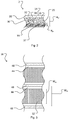
- FIG. 1A is a partial cutaway side view of a fuel cell according to an embodiment of the invention.
- FIG. 1B is a partial cutaway side view, perpendicular to the view shown in FIG. 1A , of the embodiment shown in FIG. 1A ;
- FIG. 2 is a close up partial cutaway side view of the embodiment shown in FIG. 1A ;
- FIG. 3 is a partial top view of an anode chamber according to an embodiment of the invention.
- FIGS. 4A to 4F are partial cutaway side views of various embodiments of the invention.
- FIGS. 5A to 5C are partial top views of various anode chambers according to embodiments of the invention.
- FIG. 6A is a top view of a fuel cell according to an embodiment of the invention.
- FIG. 6B is a top view of a fuel cell according to an embodiment of the invention.
- FIG. 7 is a schematic view of a metal-air fuel cell system according to an embodiment of the invention.
- fuel cell refers to an electrochemical device as would be understood by a person skilled in the art.
- fuel cell includes, without limitation, devices known as “flow batteries” and similar terminology.
- uniform as used herein with reference to an anode bed refers to an anode bed with an substantially even distribution of metal particles.
- substantially refers to the complete or nearly complete extent or degree of an action, characteristic or result.
- a “substantially” continuous pressure drop would mean that the pressure drop is either completely continuous or nearly completely continuous.
- the exact allowable degree of deviation from absolute completeness may in some cases depend on the specific context. However, generally speaking the nearness of completion will be so as to have the same overall result as if total completion were obtained.
- the use of “substantially” is equally applicable when used in a negative connotation to refer to the complete or near complete lack of an action, characteristic or result.
- “substantially” no pressure drop refers to either a complete lack of pressure drop, or a lack of pressure drop so nearly complete that the effect would be the same as if there was no pressure drop.
- “substantially” no pressure drop means that there may still be a measurable pressure drop as long as there is no measurable effect thereof.
- An alternative approach is to pump a slurry or suspension of zinc particles through the anode chamber.
- the pumping pressures are much lower, for example lower than 55.2 kPa.
- the inventors have determined that the particles make only transient contact with the anode current collector, and the current density generated is therefore limited by the number of transient contacts that are formed at any instant.
- a fuel cell with a substantially horizontally-oriented anode chamber is provided.
- Small metal particles, such as in the range of 15 nm to 300 microns, suspended in electrolyte are pumped into the anode chamber at low pressure, such as below 68.9 kPa.
- a dense bed of the metal particles is formed on an anode current collector at low electrolyte pressures by gravitational settling and one or more of: controlling the electrolyte flow rate; intermittently stopping the electrolyte flow; and providing particle collectors on the anode current collector.
- the advantages of this approach include low electrolyte pressure (to reduce pumping energy costs and mechanical stress) and small metal particle size (to increase electrical current generation), which are made possible by the anodic reaction occurring along the top of the anode bed, as well as through the anode bed. At any moment, more metal particles are in contact with each other and with the anode current collector. Thus the total surface area of metal particles contributing to the electrode reaction and generation of electrical current is much greater, in turn leading to higher energy efficiency. Electrolyte flow along and through the anode bed also removes oxidized metal reaction products from the reaction site.
- FIG. 1A shows part of a fuel cell stack 10 according to one embodiment of the invention.
- Fuel cell stack 10 is comprised of a plurality of vertically stacked fuel cells.
- FIG. 1A shows a first fuel cell 2 , and part of an identical, partial second fuel cell 2 ′ below fuel cell 2 .
- the fuel cell stack may only comprise a single fuel cell.
- the fuel cells are oriented horizontally and stacked on top of one another to form a fuel cell stack.
- the fuel cells are oriented vertically and stacked beside one another to form a fuel cell stack.
- FIG. 1B shows the alternate side view of fuel cell stack 10 as seen perpendicular to FIG. 1A .
- Fuel cell 2 of fuel cell stack 10 includes a cathode chamber 12 , cathode 14 , anode chamber 16 , anode current collector 18 and a separator 20 .
- the section of fuel cell 2 ′ of fuel cell stack 10 shown in FIG. 1A includes cathode chamber 12 ′, cathode 14 ′, and anode chamber 16 ′.
- Separator 20 prevents electrical contact between the cathode 14 and the anode chamber 16 but allows for ionic conductivity between the two.
- a contact pin 22 ′ electrically connects anode current collector 18 to cathode 14 ′ to close the circuit. In an alternate arrangement contact pin 22 ′ and anode current collector 18 are integrally formed.
- the components of fuel cell 2 of fuel cell stack 10 will be described in greater detail herein but it will be understood that the features and functions of the components of other fuel cells of fuel cell stack 10 , including fuel cell 2 ′, will correspond to those of the components of fuel cell 2 .
- cathode chamber 12 and cathode 14 are provided to extract oxygen from air flowing through cathode chamber 12 (direction of air flow represented by arrow 24 ) by electrochemical reduction of oxygen at cathode 14 , and to allow migration of formed hydroxide into anode chamber 16 (direction of oxygen extraction/reduction and hydroxide ion migration represented by arrow 26 ).
- cathode 14 is generally planar.
- Anode chamber 16 is shaped to permit metal particles 30 suspended in an electrolyte to flow therethrough in a downstream direction as represented by arrow 28 .
- the metal particles may be zinc, aluminum, beryllium, calcium, iron, lithium, magnesium, sodium, titanium, or a mixture of such metals.
- metal particles 30 are zinc particles.
- the metal particles may range in size from 5 nm to 1 mm, or 5 nm to 0.5 mm, or 5 nm to 0.3 mm.
- the electrolyte may be alkaline, such as an aqueous alkali hydroxide.
- the aqueous alkali hydroxide may be aqueous potassium hydroxide or aqueous sodium hydroxide.
- the concentration of the aqueous alkali hydroxide may range from 5% to 60% by weight, or 20% to 50% by weight, or 30% to 45% by weight.
- the electrolyte may be non-alkaline.
- anode current collector 18 is made of a material with high conductivity and high stability in aqueous alkaline solutions.
- the anode current collector may be stainless steel, nickel, iron, titanium, copper, gold, silver, magnesium, indium, lead, or carbon. In other embodiments alloys or conductive oxides of combinations of these and other elements are employed.
- anode current collector 18 is generally planar. Anode current collector 18 is disposed opposite of cathode 14 with anode chamber 16 at least partially defined therebetween.
- the surface area of each of cathode 14 and anode current collector 18 may range from 1 cm 2 to 1 m 2 . In an example embodiment, the surface area of cathode 14 and anode current collector 18 are each about 500 cm 2 and separated by about 3 mm.
- anode current collector 18 includes a plurality of particle collectors 32 projecting into anode chamber 16 .
- Particle collectors 32 may be of any shape and configuration suitable for collecting particles 30 suspended in the electrolyte and flowing through anode chamber 16 .
- particle collectors 32 are of suitable size, shape, configuration and/or array for trapping particles 30 and facilitating their formation into an anode bed 34 on anode current collector 18 .
- particle collectors 32 are of suitable size, shape, configuration and/or array for establishing a series of obstacles that perturb the flow of electrolyte through anode chamber 16 and encourage the settling of particles on or between the particle collectors.
- particle collectors 32 may be porous, or have holes, slits, and the like to enhance circulation of electrolyte.
- particle collectors 32 are formed from a conductive mesh. The mesh should limit pore sizes to a suitable size, shape, configuration and/or array to facilitate trapping particles.
- particle collectors 32 are constructed of the same conductive material as anode current collector 18 . In other embodiments particle collectors 32 may be constructed of a different conductive material or non-conductive material. In a particular embodiment, particle collectors 32 are integrally formed with anode current collector 18 . In other embodiments particle collectors 32 may be formed separately and then coupled to anode current collector 18 . In some embodiments the surface of anode current collector 18 is provided with sufficient particle collectors 32 to form a uniform anode bed 34 .
- each particle collector 32 at least partially defines an opening 35 for receiving particles 30 flowing downstream through anode chamber 16 .
- opening 35 may face a generally upstream or downstream direction.
- Each particle collector 32 also at least partially defines a pocket or well 37 shaped to accumulate trapped particles 30 therein. Opening 35 is in fluid communication with well 37 .
- opening 35 defines an opening of well 37 .
- the size of opening 35 and well 37 may be partly defined by an angle 38 defined between particle collector 32 and a planar portion of anode current collector 18 in the upstream direction.
- angle 38 may be between 5 to 90 degrees, or 20 to 70 degrees, or 30 to 60 degrees.
- angle 38 may be between 90 to 120 degrees, or 120 to 180 degrees.
- anode chamber 16 may be subdivided into a plurality of substantially parallel anode channels 44 separated by internal walls 48 .
- particle collector 32 is a laterally-elongated scoop.
- the lateral width W pc of each scoop 32 extends up to a width W ac of anode channel 44 .
- the number of particle collectors 32 per linear centimeter ranges from 0.5 to 10, or 1 to 5, or 1 to 2.
- electrolyte in adjacent channels may flow in the same direction. In other embodiments, electrolyte in adjacent channels may flow in opposite directions.
- the particle collector 32 features are microscopic and can be considered simply as an increase in surface roughness of the anode channels 44 .
- the increase in surface roughness as compared to a smooth planar surface ranges from 4:1 to 10,000:1, or 10:1 to 1000:1, or 50:1 to 500:1.
- particle collectors 32 may be arranged in a staggered array or other repeating or random array that facilitates formation of a uniform anode bed 34 and does not interfere with uniform flow of electrolyte.
- FIGS. 5A to 5C show non-limiting examples of top views of other possible configurations of particle collectors 32 .
- the height H pc of particle collector 32 is limited to a height that does not significantly impede the flow of electrolyte through anode chamber 16 .
- height H pc relative to the planar portion of anode current collector 18 ranges from 0.2 mm to 5.0 mm, or 0.5 to 3.0 mm, or 1.0 to 2.0 mm.
- a ratio of height H pc to the height of the anode chamber 16 (H ac ) ranges from 0.1 to 0.6, or 0.2 to 0.5, or 0.3 to 0.4.
- anode bed 34 is controlled (as described further below) to ensure it does not significantly impede the flow of electrolyte through anode chamber 16 .
- the depth D ab of anode bed 34 does not exceed the height H pc of particle collectors 32 .
- anode bed 34 may have a depth D ab ranging from 0.2 mm to 20 mm, or 1 mm to 10 mm, or 2 mm to 4 mm, or 0.5 mm to 2 mm, and in some embodiments anode bed 34 may have a depth D ab wherein a ratio of depth D ab to a height of the anode chamber H ac ranges from 0.1 to 0.6, or 0.2 to 0.5, or 0.3 to 0.4. In some embodiments, depth D ab is uniform across most or all of anode bed 34 .
- anode chamber 16 includes an inlet 40 , an outlet 42 , and a plurality of channels 44 linked in a serpentine manner.
- each channel 44 is dimensioned to facilitate uniform flow of electrolyte therethrough characterized by a substantially continuous pressure drop of electrolyte in the direction of electrolyte flow and substantially no pressure drop in the lateral direction.
- each channel 44 has a length to width aspect ratio of 50:1 to 2:1, 25:1 to 4:1, or 10:1 to 5:1.
- channels 44 may be arranged in other configurations, such as in a parallel flow configuration as shown in FIG. 6B .
- Anode chamber 16 includes an inlet 40 , an outlet 42 , and a plurality of channels 44 linked in a parallel manner.
- each channel 44 is dimensioned to facilitate uniform flow of electrolyte therethrough characterized by a substantially continuous pressure drop of electrolyte in the direction of electrolyte flow and substantially no pressure drop in the lateral direction.
- each channel 44 has a length to width aspect ratio of 50:1 to 2:1, 25:1 to 4:1, or 10:1 to 5:1.
- a manifold 56 is used to facilitate distribution amongst parallel flow channels.
- channels 44 can be formed as combinations of serpentine and parallel flow channels.
- metal particles 30 suspended in electrolyte are loaded into anode chamber 16 and air is loaded into cathode chamber 14 .
- a uniform bed of metal particles 30 is controllably formed on anode current collector 18 by one or more of the following mechanisms: (i) maintaining the flow of metal particles 30 suspended in the electrolyte at a predetermined flow rate slow enough to allow some metal particles 30 to settle onto anode current collector 18 ; (ii) periodically stopping the flow of metal particles 30 suspended in the electrolyte to allow some metal particles 30 to settle onto anode current collector 18 ; and (iii) providing a plurality of particle collectors 32 as described herein on anode current collector 18 to collect metal particles 30 .
- anode chamber 16 is oriented substantially horizontally to allow particles 30 to settle by gravity to form anode bed 34 on anode current collector 18 .
- Particles 30 of anode bed 34 are therefore in contact with anode current collector 18 and/or with other particles 30 in anode bed 34 .
- the particles 30 along the top of anode bed 34 then undergo the anodic reaction.
- the anodic reaction occurs principally at the top of anode bed 34 , and decreases in a direction downwards towards anode current collector 18 .
- Current may be drawn from fuel cell 2 by closing the circuit between cathode 14 and anode current collector 18 and applying a load.
- Current drawn through a fuel cell stack is facilitated by connecting the end plates and individual fuel cells are connected, for example with contact pin 22 , and applying a load.
- a current density of 50 mA/cm 2 or greater is drawn by the load and discharge occurs for periods ranging from 1 to 20 hours.
- fuel cell 2 or fuel cell stack 10 is maintained in a substantially fully charged state even in a suspended state of active reaction by disconnecting the load.
- a substantially fully charged state of fuel cell 2 or fuel cell stack 10 is preserved by maintenance of a fully filled anode bed 34 .
- Formation of a uniform bed of particles 30 on anode current collector 18 is also facilitated by providing a uniform flow of the electrolyte through anode chamber 16 .
- Uniform flow is achieved by providing a substantially continuous pressure drop in a downstream direction in anode chamber 16 and minimal or substantially no lateral pressure drop.
- electrolyte throughout anode chamber 16 moves at substantially the same flow velocity, with substantially no areas of recirculation or “dead zones” of little or no flow.
- the flow rate of the electrolyte in anode chamber 16 ranges from 1 L/min. to 7 L/min., or 3 L/min. to 7 L/min., or 3 L/min. to 5 L/min.
- electrolyte is loaded into anode chamber 16 at a gauge pressure ranging from 0.69 kPa to 103.4 kPa, or 6.9 kPa to 82.7 kPa, or 13.8 kPa to 68.9 kPa. In some embodiments, the gauge pressure of electrolyte in the anode chamber is less than 34.5 kPa. Gauge pressure refers to pressure zero-referenced against atmospheric air pressure (i.e., the difference between absolute pressure and atmospheric pressure).
- FIG. 7 shows a metal-air fuel cell system 200 according to one embodiment of the invention.
- System 200 includes a fuel cell 210 , an electrolyzer 220 and a fresh fuel tank 230 .
- Fuel cell 210 may for example comprise a fuel cell 2 .
- Fuel cell 210 may also comprise a plurality of fuel cells 2 to form a fuel cell stack.
- One or more pumps pump electrolyte and metal particles and/or product species through system 200 .
- spent fuel e.g., oxidized metal, such as zincate
- tank 230 where it can be stored.
- the spent fuel can then be pumped from tank 230 to electrolyzer 220 .
- spent fuel may be pumped from fuel cell 210 directly to electrolyzer 220 .
- Electrolyzer 220 regenerates the metal fuel, which is subsequently pumped to tank 230 .
- the metal fuel may for example be dendritic zinc powder ranging in size from 5 nm to 1 mm, 5 nm to 0.5 mm, or 5 nm to 0.3 mm. This metal fuel is stored in tank 230 until required for use by fuel cell 210 . In some embodiments regenerated metal fuel may be pumped directly back into fuel cell 210 .
- a component e.g. cathode, anode current collector, etc.
- reference to that component should be interpreted as including as equivalents of that component any component which performs the function of the described component (i.e., that is functionally equivalent), including components which are not structurally equivalent to the disclosed structure which performs the function in the illustrated exemplary embodiments of the invention.
Landscapes
- Chemical & Material Sciences (AREA)
- Chemical Kinetics & Catalysis (AREA)
- Electrochemistry (AREA)
- General Chemical & Material Sciences (AREA)
- Manufacturing & Machinery (AREA)
- Engineering & Computer Science (AREA)
- Life Sciences & Earth Sciences (AREA)
- Sustainable Development (AREA)
- Sustainable Energy (AREA)
- Dispersion Chemistry (AREA)
- Inert Electrodes (AREA)
- Fuel Cell (AREA)
- Hybrid Cells (AREA)
Priority Applications (2)
| Application Number | Priority Date | Filing Date | Title |
|---|---|---|---|
| US15/923,256 US10826142B2 (en) | 2015-09-17 | 2018-03-16 | Metal-air fuel cell |
| US17/036,642 US11245144B2 (en) | 2015-09-17 | 2020-09-29 | Metal-air fuel cell |
Applications Claiming Priority (3)
| Application Number | Priority Date | Filing Date | Title |
|---|---|---|---|
| US201562219984P | 2015-09-17 | 2015-09-17 | |
| PCT/CA2016/051080 WO2017045072A1 (fr) | 2015-09-17 | 2016-09-13 | Pile à combustible métal-air |
| US15/923,256 US10826142B2 (en) | 2015-09-17 | 2018-03-16 | Metal-air fuel cell |
Related Parent Applications (1)
| Application Number | Title | Priority Date | Filing Date |
|---|---|---|---|
| PCT/CA2016/051080 Continuation WO2017045072A1 (fr) | 2015-09-17 | 2016-09-13 | Pile à combustible métal-air |
Related Child Applications (1)
| Application Number | Title | Priority Date | Filing Date |
|---|---|---|---|
| US17/036,642 Division US11245144B2 (en) | 2015-09-17 | 2020-09-29 | Metal-air fuel cell |
Publications (2)
| Publication Number | Publication Date |
|---|---|
| US20180212294A1 US20180212294A1 (en) | 2018-07-26 |
| US10826142B2 true US10826142B2 (en) | 2020-11-03 |
Family
ID=58287960
Family Applications (2)
| Application Number | Title | Priority Date | Filing Date |
|---|---|---|---|
| US15/923,256 Expired - Fee Related US10826142B2 (en) | 2015-09-17 | 2018-03-16 | Metal-air fuel cell |
| US17/036,642 Expired - Fee Related US11245144B2 (en) | 2015-09-17 | 2020-09-29 | Metal-air fuel cell |
Family Applications After (1)
| Application Number | Title | Priority Date | Filing Date |
|---|---|---|---|
| US17/036,642 Expired - Fee Related US11245144B2 (en) | 2015-09-17 | 2020-09-29 | Metal-air fuel cell |
Country Status (8)
| Country | Link |
|---|---|
| US (2) | US10826142B2 (fr) |
| EP (1) | EP3350867B1 (fr) |
| JP (1) | JP2018528595A (fr) |
| KR (1) | KR102576974B1 (fr) |
| CN (1) | CN108140919B (fr) |
| AU (1) | AU2016322029B2 (fr) |
| CA (1) | CA2999069C (fr) |
| WO (1) | WO2017045072A1 (fr) |
Families Citing this family (11)
| Publication number | Priority date | Publication date | Assignee | Title |
|---|---|---|---|---|
| DE102015215201A1 (de) * | 2015-08-10 | 2017-02-16 | Volkswagen Ag | Brennstoffzellenstapel mit interner Partikelzurückhaltefunktion sowie Fahrzeug mit einem solchen Brennstoffzellenstapel |
| CN107019915B (zh) | 2016-02-01 | 2018-09-07 | 腾讯科技(深圳)有限公司 | 一种确定移动轨迹的方法、用户设备及系统 |
| AU2017298995B2 (en) | 2016-07-22 | 2019-08-29 | Form Energy, Inc. | Mist elimination system for electrochemical cells |
| JP2019521497A (ja) | 2016-07-22 | 2019-07-25 | ナントエナジー,インク. | 電気化学セル内の水分及び二酸化炭素管理システム |
| US12261281B2 (en) * | 2018-06-29 | 2025-03-25 | Form Energy, Inc. | Metal air electrochemical cell architecture |
| US12237548B2 (en) | 2018-06-29 | 2025-02-25 | Form Energy, Inc. | Stack of electric batteries including series of fluidly connected unit cells |
| US12308414B2 (en) | 2019-06-28 | 2025-05-20 | Form Energy, Inc. | Device architectures for metal-air batteries |
| CN111537900B (zh) * | 2020-04-07 | 2021-03-16 | 清华大学 | 金属空气燃料电池耐久性综合测试评价方法 |
| US12381244B2 (en) | 2020-05-06 | 2025-08-05 | Form Energy, Inc. | Decoupled electrode electrochemical energy storage system |
| CN119366007A (zh) * | 2022-06-08 | 2025-01-24 | 锌能公司 | 用于电化学电池的具有嵌入电极材料的充电阴极组件 |
| JP2025171165A (ja) * | 2024-05-09 | 2025-11-20 | シャープ株式会社 | フロー型電池セル、フロー型金属空気電池セル、フロー型電池、フロー型金属空気電池 |
Citations (13)
| Publication number | Priority date | Publication date | Assignee | Title |
|---|---|---|---|---|
| US3849202A (en) | 1971-12-20 | 1974-11-19 | Co General D Electricite | Method of manufacturing a metal-air battery |
| US4038458A (en) | 1975-01-14 | 1977-07-26 | Compagnie Generale D'electricite S.A. | Zinc-air electrochemical cell |
| US4139679A (en) | 1976-12-03 | 1979-02-13 | Compagnie Generale D'electricite | Rechargeable electrochemical system |
| US4517258A (en) | 1982-10-21 | 1985-05-14 | T.R.E.G.I.E. | Electrochemical generator operating device with a zinc negative electrode |
| EP0458395A1 (fr) | 1990-05-23 | 1991-11-27 | Stork Screens B.V. | Procédé de charge d'un accumulateur à suspension de zinc; accumulateur à suspension de zinc et suspension de zinc utilisable dans un accumulateur |
| US5434020A (en) | 1993-11-15 | 1995-07-18 | The Regents Of The University Of California | Continuous-feed electrochemical cell with nonpacking particulate electrode |
| US5849427A (en) | 1993-12-02 | 1998-12-15 | Lawrence Berkeley Laboratory | Hydraulically refueled battery employing a packed bed metal particle electrode |
| US20040053132A1 (en) | 2002-09-12 | 2004-03-18 | Smedley Stuart I. | Improved fuel for a zinc-based fuel cell and regeneration thereof |
| US6787260B2 (en) | 2002-09-12 | 2004-09-07 | Metallic Power, Inc. | Electrolyte-particulate fuel cell anode |
| US20090075170A1 (en) | 2007-09-13 | 2009-03-19 | The Regents Of The University Of California | Continuous-feed electrochemical cell |
| US20110207001A1 (en) | 2008-11-10 | 2011-08-25 | Paolo Bert | Rechargeable zinc-air battery |
| US20120034541A1 (en) * | 2009-04-01 | 2012-02-09 | Masashi Muraoka | Fuel cell stack and electronic device provided with the same |
| US20140370401A1 (en) | 2012-08-01 | 2014-12-18 | Sharp Laboratories of America (SLA), Inc. | Air Cathode Battery Using Zinc Slurry Anode with Carbon Additive |
Family Cites Families (2)
| Publication number | Priority date | Publication date | Assignee | Title |
|---|---|---|---|---|
| US6558825B1 (en) * | 2000-05-12 | 2003-05-06 | Reveo, Inc. | Fuel containment and recycling system |
| CN2777770Y (zh) * | 2004-09-20 | 2006-05-03 | 北京长力联合能源技术有限公司 | 锌空气电池能量补给系统 |
-
2016
- 2016-09-13 KR KR1020187010197A patent/KR102576974B1/ko active Active
- 2016-09-13 CA CA2999069A patent/CA2999069C/fr active Active
- 2016-09-13 AU AU2016322029A patent/AU2016322029B2/en not_active Ceased
- 2016-09-13 EP EP16845423.9A patent/EP3350867B1/fr active Active
- 2016-09-13 CN CN201680053802.6A patent/CN108140919B/zh active Active
- 2016-09-13 JP JP2018533981A patent/JP2018528595A/ja active Pending
- 2016-09-13 WO PCT/CA2016/051080 patent/WO2017045072A1/fr not_active Ceased
-
2018
- 2018-03-16 US US15/923,256 patent/US10826142B2/en not_active Expired - Fee Related
-
2020
- 2020-09-29 US US17/036,642 patent/US11245144B2/en not_active Expired - Fee Related
Patent Citations (13)
| Publication number | Priority date | Publication date | Assignee | Title |
|---|---|---|---|---|
| US3849202A (en) | 1971-12-20 | 1974-11-19 | Co General D Electricite | Method of manufacturing a metal-air battery |
| US4038458A (en) | 1975-01-14 | 1977-07-26 | Compagnie Generale D'electricite S.A. | Zinc-air electrochemical cell |
| US4139679A (en) | 1976-12-03 | 1979-02-13 | Compagnie Generale D'electricite | Rechargeable electrochemical system |
| US4517258A (en) | 1982-10-21 | 1985-05-14 | T.R.E.G.I.E. | Electrochemical generator operating device with a zinc negative electrode |
| EP0458395A1 (fr) | 1990-05-23 | 1991-11-27 | Stork Screens B.V. | Procédé de charge d'un accumulateur à suspension de zinc; accumulateur à suspension de zinc et suspension de zinc utilisable dans un accumulateur |
| US5434020A (en) | 1993-11-15 | 1995-07-18 | The Regents Of The University Of California | Continuous-feed electrochemical cell with nonpacking particulate electrode |
| US5849427A (en) | 1993-12-02 | 1998-12-15 | Lawrence Berkeley Laboratory | Hydraulically refueled battery employing a packed bed metal particle electrode |
| US20040053132A1 (en) | 2002-09-12 | 2004-03-18 | Smedley Stuart I. | Improved fuel for a zinc-based fuel cell and regeneration thereof |
| US6787260B2 (en) | 2002-09-12 | 2004-09-07 | Metallic Power, Inc. | Electrolyte-particulate fuel cell anode |
| US20090075170A1 (en) | 2007-09-13 | 2009-03-19 | The Regents Of The University Of California | Continuous-feed electrochemical cell |
| US20110207001A1 (en) | 2008-11-10 | 2011-08-25 | Paolo Bert | Rechargeable zinc-air battery |
| US20120034541A1 (en) * | 2009-04-01 | 2012-02-09 | Masashi Muraoka | Fuel cell stack and electronic device provided with the same |
| US20140370401A1 (en) | 2012-08-01 | 2014-12-18 | Sharp Laboratories of America (SLA), Inc. | Air Cathode Battery Using Zinc Slurry Anode with Carbon Additive |
Non-Patent Citations (4)
| Title |
|---|
| International Preliminary Report on Patentability dated Jun. 1, 2017 for International Application No. PCT/CA2016/051080 (34 pages). |
| International Search Report dated Nov. 25, 2016 for International Application No. PCT/CA2016/051080 (6 pages). |
| Jiratchayamaethasakul, C. et al. (2014). Effects of anode orientation and flow channel design on performance of refuelable zinc-air fuel cells. Journal of Applied Electrochemistry, 44(11), 1205-1218. doi: 10.1007/s (Year: 2014). * |
| Written Opinion of the International Searching Authority dated Nov. 25, 2016 for International Application No. PCT/CA2016/051080 (7 pages). |
Also Published As
| Publication number | Publication date |
|---|---|
| JP2018528595A (ja) | 2018-09-27 |
| AU2016322029B2 (en) | 2021-12-02 |
| CA2999069C (fr) | 2023-10-17 |
| WO2017045072A1 (fr) | 2017-03-23 |
| EP3350867A1 (fr) | 2018-07-25 |
| EP3350867A4 (fr) | 2019-09-04 |
| KR20180052719A (ko) | 2018-05-18 |
| CN108140919B (zh) | 2021-03-23 |
| US11245144B2 (en) | 2022-02-08 |
| US20180212294A1 (en) | 2018-07-26 |
| CA2999069A1 (fr) | 2017-03-23 |
| EP3350867B1 (fr) | 2021-12-29 |
| KR102576974B1 (ko) | 2023-09-15 |
| AU2016322029A1 (en) | 2018-04-12 |
| CN108140919A (zh) | 2018-06-08 |
| US20210083346A1 (en) | 2021-03-18 |
Similar Documents
| Publication | Publication Date | Title |
|---|---|---|
| US11245144B2 (en) | Metal-air fuel cell | |
| EP2586092B1 (fr) | Pile électrochimique avec anode à combustible échelonnée décalée | |
| US20040053132A1 (en) | Improved fuel for a zinc-based fuel cell and regeneration thereof | |
| CN104106157B (zh) | 可再充电的锌空气电池及其操作方法 | |
| CN104584319B (zh) | 金属空气电池 | |
| US8962197B2 (en) | Electrolyte system for metal-air batteries and methods of use thereof | |
| US9742048B2 (en) | Metal-air battery | |
| US4039729A (en) | Rechargeable galvanic cell with zinc electrode and auxiliary structure | |
| KR20240035803A (ko) | 이온 션트 전류 제거를 위한 장치 및 방법 | |
| US9608264B2 (en) | Air cathode battery using zinc slurry anode with carbon additive | |
| WO2004025766A1 (fr) | Anode de pile a combustible amelioree a particules electrolytiques | |
| KR20010015693A (ko) | 금속을 산화시키고 산화 기체를 환원시켜 전기를발생시키는 전기 화학 발전기 | |
| JP7851064B2 (ja) | フロー型電池セル | |
| JP7853937B2 (ja) | フロー型金属空気電池用充電部 | |
| NL2014744A (en) | Hybrid battery and electrolyser. | |
| JP2025040445A (ja) | フロー型金属空気電池用充電セル | |
| JP7758712B2 (ja) | フロー型電池セルおよびフロー型金属空気電池 | |
| JP2026006191A (ja) | 発電部スタックおよびフロー型金属空気電池 | |
| JP6692218B2 (ja) | 電力貯蔵デバイス | |
| KR102032184B1 (ko) | 금속 포일 지지체형 박형 양극, 이를 포함하는 아연-니켈 플로우 전지 | |
| JP2026012602A (ja) | 二次電池システム | |
| KR20240060622A (ko) | 전기 이중층 커패시터를 통한 전자 전도 기능을 갖는 전지 | |
| WO2014073410A1 (fr) | Cellule métal-air | |
| KR101575211B1 (ko) | 금속 공기 전지 유닛 |
Legal Events
| Date | Code | Title | Description |
|---|---|---|---|
| FEPP | Fee payment procedure |
Free format text: ENTITY STATUS SET TO UNDISCOUNTED (ORIGINAL EVENT CODE: BIG.); ENTITY STATUS OF PATENT OWNER: SMALL ENTITY |
|
| FEPP | Fee payment procedure |
Free format text: ENTITY STATUS SET TO SMALL (ORIGINAL EVENT CODE: SMAL); ENTITY STATUS OF PATENT OWNER: SMALL ENTITY |
|
| STPP | Information on status: patent application and granting procedure in general |
Free format text: DOCKETED NEW CASE - READY FOR EXAMINATION |
|
| AS | Assignment |
Owner name: MGX RENEWABLES INC., CANADA Free format text: ASSIGNMENT OF ASSIGNORS INTEREST;ASSIGNORS:SMEDLEY, STUART;TIVY, WOLF;WOZNICZKA, BOGUSLAW;AND OTHERS;SIGNING DATES FROM 20151127 TO 20151220;REEL/FRAME:048722/0360 |
|
| STPP | Information on status: patent application and granting procedure in general |
Free format text: NON FINAL ACTION MAILED |
|
| STPP | Information on status: patent application and granting procedure in general |
Free format text: RESPONSE TO NON-FINAL OFFICE ACTION ENTERED AND FORWARDED TO EXAMINER |
|
| STPP | Information on status: patent application and granting procedure in general |
Free format text: NON FINAL ACTION MAILED |
|
| AS | Assignment |
Owner name: ZINC8 ENERGY SOLUTIONS INC., CANADA Free format text: CHANGE OF NAME;ASSIGNOR:MGX RENEWABLES INC.;REEL/FRAME:052273/0765 Effective date: 20200317 |
|
| STPP | Information on status: patent application and granting procedure in general |
Free format text: RESPONSE TO NON-FINAL OFFICE ACTION ENTERED AND FORWARDED TO EXAMINER |
|
| STPP | Information on status: patent application and granting procedure in general |
Free format text: FINAL REJECTION MAILED |
|
| STPP | Information on status: patent application and granting procedure in general |
Free format text: RESPONSE AFTER FINAL ACTION FORWARDED TO EXAMINER |
|
| STPP | Information on status: patent application and granting procedure in general |
Free format text: PUBLICATIONS -- ISSUE FEE PAYMENT VERIFIED |
|
| STCF | Information on status: patent grant |
Free format text: PATENTED CASE |
|
| FEPP | Fee payment procedure |
Free format text: MAINTENANCE FEE REMINDER MAILED (ORIGINAL EVENT CODE: REM.); ENTITY STATUS OF PATENT OWNER: SMALL ENTITY |
|
| LAPS | Lapse for failure to pay maintenance fees |
Free format text: PATENT EXPIRED FOR FAILURE TO PAY MAINTENANCE FEES (ORIGINAL EVENT CODE: EXP.); ENTITY STATUS OF PATENT OWNER: SMALL ENTITY |
|
| STCH | Information on status: patent discontinuation |
Free format text: PATENT EXPIRED DUE TO NONPAYMENT OF MAINTENANCE FEES UNDER 37 CFR 1.362 |
|
| FP | Lapsed due to failure to pay maintenance fee |
Effective date: 20241103 |