US10862815B2 - Method for managing packets for V2X communication and apparatus therefor - Google Patents
Method for managing packets for V2X communication and apparatus therefor Download PDFInfo
- Publication number
- US10862815B2 US10862815B2 US16/097,765 US201716097765A US10862815B2 US 10862815 B2 US10862815 B2 US 10862815B2 US 201716097765 A US201716097765 A US 201716097765A US 10862815 B2 US10862815 B2 US 10862815B2
- Authority
- US
- United States
- Prior art keywords
- packet
- layer
- buffer
- information
- pdcp
- Prior art date
- Legal status (The legal status is an assumption and is not a legal conclusion. Google has not performed a legal analysis and makes no representation as to the accuracy of the status listed.)
- Active, expires
Links
- 238000004891 communication Methods 0.000 title claims abstract description 58
- 238000000034 method Methods 0.000 title claims abstract description 41
- 238000001514 detection method Methods 0.000 claims description 6
- 230000005540 biological transmission Effects 0.000 description 27
- 230000006870 function Effects 0.000 description 24
- 238000010586 diagram Methods 0.000 description 20
- 238000007726 management method Methods 0.000 description 8
- 230000011664 signaling Effects 0.000 description 8
- 230000006399 behavior Effects 0.000 description 5
- 230000007774 longterm Effects 0.000 description 5
- 238000013475 authorization Methods 0.000 description 4
- 230000008569 process Effects 0.000 description 4
- 238000013468 resource allocation Methods 0.000 description 4
- 230000008054 signal transmission Effects 0.000 description 4
- 230000006835 compression Effects 0.000 description 3
- 238000007906 compression Methods 0.000 description 3
- 238000005516 engineering process Methods 0.000 description 3
- 238000001914 filtration Methods 0.000 description 3
- 230000003993 interaction Effects 0.000 description 3
- 238000012544 monitoring process Methods 0.000 description 3
- 238000012545 processing Methods 0.000 description 3
- 230000004044 response Effects 0.000 description 3
- 230000008901 benefit Effects 0.000 description 2
- 239000000969 carrier Substances 0.000 description 2
- 238000010276 construction Methods 0.000 description 2
- 125000004122 cyclic group Chemical group 0.000 description 2
- 230000000694 effects Effects 0.000 description 2
- 238000012546 transfer Methods 0.000 description 2
- 230000007704 transition Effects 0.000 description 2
- 238000012384 transportation and delivery Methods 0.000 description 2
- 241000760358 Enodes Species 0.000 description 1
- 101000741965 Homo sapiens Inactive tyrosine-protein kinase PRAG1 Proteins 0.000 description 1
- 102100038659 Inactive tyrosine-protein kinase PRAG1 Human genes 0.000 description 1
- 230000003321 amplification Effects 0.000 description 1
- 238000003491 array Methods 0.000 description 1
- 230000033228 biological regulation Effects 0.000 description 1
- 230000015572 biosynthetic process Effects 0.000 description 1
- 238000006243 chemical reaction Methods 0.000 description 1
- 239000013256 coordination polymer Substances 0.000 description 1
- 238000013500 data storage Methods 0.000 description 1
- 230000001419 dependent effect Effects 0.000 description 1
- 230000010354 integration Effects 0.000 description 1
- 239000004973 liquid crystal related substance Substances 0.000 description 1
- 238000013507 mapping Methods 0.000 description 1
- 239000011159 matrix material Substances 0.000 description 1
- 230000007246 mechanism Effects 0.000 description 1
- 238000010295 mobile communication Methods 0.000 description 1
- 238000003199 nucleic acid amplification method Methods 0.000 description 1
- 238000005070 sampling Methods 0.000 description 1
- 230000011218 segmentation Effects 0.000 description 1
- 230000003595 spectral effect Effects 0.000 description 1
- 238000013519 translation Methods 0.000 description 1
Images


Classifications
-
- H—ELECTRICITY
- H04—ELECTRIC COMMUNICATION TECHNIQUE
- H04L—TRANSMISSION OF DIGITAL INFORMATION, e.g. TELEGRAPHIC COMMUNICATION
- H04L47/00—Traffic control in data switching networks
- H04L47/10—Flow control; Congestion control
- H04L47/32—Flow control; Congestion control by discarding or delaying data units, e.g. packets or frames
-
- H—ELECTRICITY
- H04—ELECTRIC COMMUNICATION TECHNIQUE
- H04L—TRANSMISSION OF DIGITAL INFORMATION, e.g. TELEGRAPHIC COMMUNICATION
- H04L43/00—Arrangements for monitoring or testing data switching networks
- H04L43/16—Threshold monitoring
-
- H—ELECTRICITY
- H04—ELECTRIC COMMUNICATION TECHNIQUE
- H04L—TRANSMISSION OF DIGITAL INFORMATION, e.g. TELEGRAPHIC COMMUNICATION
- H04L47/00—Traffic control in data switching networks
- H04L47/10—Flow control; Congestion control
- H04L47/24—Traffic characterised by specific attributes, e.g. priority or QoS
-
- H—ELECTRICITY
- H04—ELECTRIC COMMUNICATION TECHNIQUE
- H04L—TRANSMISSION OF DIGITAL INFORMATION, e.g. TELEGRAPHIC COMMUNICATION
- H04L47/00—Traffic control in data switching networks
- H04L47/10—Flow control; Congestion control
- H04L47/30—Flow control; Congestion control in combination with information about buffer occupancy at either end or at transit nodes
-
- H—ELECTRICITY
- H04—ELECTRIC COMMUNICATION TECHNIQUE
- H04W—WIRELESS COMMUNICATION NETWORKS
- H04W4/00—Services specially adapted for wireless communication networks; Facilities therefor
- H04W4/30—Services specially adapted for particular environments, situations or purposes
- H04W4/40—Services specially adapted for particular environments, situations or purposes for vehicles, e.g. vehicle-to-pedestrians [V2P]
Definitions
- the present invention relates to a wireless communication system and, more particularly, to a method for managing packets for a V2X (Vehicle-to-Everything) communication and an apparatus therefor.
- V2X Vehicle-to-Everything
- LTE 3rd Generation Partnership Project Long Term Evolution
- FIG. 1 is a view schematically illustrating a network structure of an E-UMTS as an exemplary radio communication system.
- An Evolved Universal Mobile Telecommunications System (E-UMTS) is an advanced version of a conventional Universal Mobile Telecommunications System (UMTS) and basic standardization thereof is currently underway in the 3GPP.
- E-UMTS may be generally referred to as a Long Term Evolution (LTE) system.
- LTE Long Term Evolution
- the E-UMTS includes a User Equipment (UE), eNode Bs (eNBs), and an Access Gateway (AG) which is located at an end of the network (E-UTRAN) and connected to an external network.
- the eNBs may simultaneously transmit multiple data streams for a broadcast service, a multicast service, and/or a unicast service.
- One or more cells are present per eNB.
- a cell is configured to use one of bandwidths of 1.44, 3, 5, 10, 15, and 20 MHz to provide a downlink or uplink transport service to several UEs. Different cells may be set to provide different bandwidths.
- the eNB controls data transmission and reception for a plurality of UEs.
- the eNB transmits downlink scheduling information with respect to downlink data to notify a corresponding UE of a time/frequency domain in which data is to be transmitted, coding, data size, and Hybrid Automatic Repeat and reQuest (HARQ)-related information.
- HARQ Hybrid Automatic Repeat and reQuest
- the eNB transmits uplink scheduling information with respect to uplink data to a corresponding UE to inform the UE of an available time/frequency domain, coding, data size, and HARQ-related information.
- An interface may be used to transmit user traffic or control traffic between eNBs.
- a Core Network (CN) may include the AG, a network node for user registration of the UE, and the like.
- the AG manages mobility of a UE on a Tracking Area (TA) basis, each TA including a plurality of cells.
- TA Tracking Area
- radio communication technology has been developed up to LTE based on Wideband Code Division Multiple Access (WCDMA)
- WCDMA Wideband Code Division Multiple Access
- demands and expectations of users and providers continue to increase.
- new advances in technology are required to secure future competitiveness. For example, decrease of cost per bit, increase of service availability, flexible use of a frequency band, simple structure, open interface, and suitable power consumption by a UE are required.
- the present invention proposes a method for managing packets for a V2X (Vehicle-to-Everything) communication and an apparatus therefor.
- V2X Vehicle-to-Everything
- a method for discarding at least one packet by a user equipment (UE) in a wireless communication system includes the steps of storing the at least one packet received from an upper layer in a buffer; determining whether or not a number of packets in the buffer is equal to or greater than a threshold value; and discarding the at least one packet from the buffer when the number of packets in the buffer is equal to or greater than the threshold value.
- UE user equipment
- a user equipment (UE) in a wireless communication system comprises a radio frequency (RF) unit; and a processor connected with the RF unit and configured to store the at least one packet received from an upper layer in a buffer, determine whether or not a number of packets in the buffer is equal to or greater than a threshold, and discard the at least one packet from the buffer when the number of packets in the buffer is equal to or greater than the threshold value.
- RF radio frequency
- the at least one packet is discarded upon a detection of ingress of another packet into the buffer.
- the determining comprises determining whether or not a number of packets having same priority in the buffer is equal to or greater than the threshold value.
- information about the threshold value may be provided from the network.
- the threshold value is configured per bearer
- the present invention it is preferable to determine whether a zone in which the UE is located is changed or not. In this case, when the zone is changed, the at least one packet is discarded from the buffer.
- the UE can manage packets efficiently for the V2X communication.
- FIG. 1 is a diagram showing a network structure of an Evolved Universal Mobile Telecommunications System (E-UMTS) as an example of a wireless communication system.
- E-UMTS Evolved Universal Mobile Telecommunications System
- FIG. 2 is a diagram showing the concept of a network structure of an Evolved Universal Terrestrial Radio Access Network (E-UTRAN).
- E-UTRAN Evolved Universal Terrestrial Radio Access Network
- FIG. 3 is a diagram showing a control plane and a user plane of a radio interface protocol between a User Equipment (UE) and an Evolved Universal Terrestrial Radio Access Network (E-UTRAN) based on a 3rd Generation Partnership Project (3GPP) radio access network standard.
- UE User Equipment
- E-UTRAN Evolved Universal Terrestrial Radio Access Network
- 3GPP 3rd Generation Partnership Project
- FIG. 4 is a diagram showing physical channels used in a 3GPP system and a general signal transmission method using the same.
- FIG. 5 is a diagram showing the structure of a radio frame used in a Long Term Evolution (LTE) system.
- LTE Long Term Evolution
- FIG. 6 is an example of default data path for a normal communication
- FIGS. 7 and 8 are examples of data path scenarios for a proximity communication
- FIG. 9 is a conceptual diagram illustrating for a non-roaming reference architecture
- FIG. 10 is a conceptual diagram illustrating for a Layer 2 Structure for Sidelink
- FIG. 11 is a conceptual diagram illustrating for protocol stack for ProSe Direct Communication
- FIG. 12 is a conceptual diagram illustrating for a PC5 interface for ProSe Direct Discovery
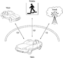
- FIG. 13 is a conceptual diagram illustrating for Vehicle-to-Everything (V2X) communication
- FIG. 14 is a flow chart illustrating an operation in accordance with an embodiment of the present invention.
- FIG. 15 is a block diagram of a communication apparatus according to an embodiment of the present invention.
- LTE long term evolution
- LTE-A LTE-advanced
- the embodiments of the present invention are applicable to any other communication system corresponding to the above definition.
- the embodiments of the present invention are described based on a frequency division duplex (FDD) scheme in the present specification, the embodiments of the present invention may be easily modified and applied to a half-duplex FDD (H-FDD) scheme or a time division duplex (TDD) scheme.
- FDD frequency division duplex
- H-FDD half-duplex FDD
- TDD time division duplex
- FIG. 2 is a diagram showing the concept of a network structure of an Evolved Universal Terrestrial Radio Access Network (E-UTRAN).
- E-UTRAN Evolved Universal Terrestrial Radio Access Network
- the E-UTRAN includes cells (eNBs) and cells are connected via an X2 interface.
- a cell is connected to a user equipment (UE) via an air interface and is connected to an evolved packet core (EPC) via an S1 interface.
- UE user equipment
- EPC evolved packet core
- the EPC includes a mobility management entity (MME), a serving-gateway (S-GW) and a packet data network-gateway (PDN-GW).
- MME mobility management entity
- S-GW serving-gateway
- PDN-GW packet data network-gateway
- the MME has access information of a UE and information about capabilities of the UE. Such information is mainly used for mobility management of the UE.
- the S-GW is a gateway having an E-UTRAN as an end point and the PDN-GW is a gateway having a PDN as an end point.
- FIG. 3 shows a control plane and a user plane of a radio interface protocol between a UE and an Evolved Universal Terrestrial Radio Access Network (E-UTRAN) based on a 3GPP radio access network standard.
- the control plane refers to a path used for transmitting control messages used for managing a call between the UE and the network.
- the user plane refers to a path used for transmitting data generated in an application layer, e.g., voice data or Internet packet data.
- a physical (PHY) layer of a first layer provides an information transfer service to a higher layer using a physical channel.
- the PHY layer is connected to a Medium Access Control (MAC) layer located on a higher layer via a transport channel. Data is transported between the MAC layer and the PHY layer via the transport channel. Data is also transported between a physical layer of a transmitting side and a physical layer of a receiving side via a physical channel.
- the physical channel uses a time and a frequency as radio resources. More specifically, the physical channel is modulated using an Orthogonal Frequency Division Multiple Access (OFDMA) scheme in downlink and is modulated using a Single-Carrier Frequency Division Multiple Access (SC-FDMA) scheme in uplink.
- OFDMA Orthogonal Frequency Division Multiple Access
- SC-FDMA Single-Carrier Frequency Division Multiple Access
- a medium access control (MAC) layer, a radio link control (RLC) layer and a packet data convergence protocol (PDCP) layer may be located in a second layer.
- the MAC layer of the second layer serves to map various logical channels to various transport channels.
- the MAC layer performs a logical channel multiplexing function for mapping several logical channels to one transport channel.
- the MAC layer is connected to a Radio Link Control (RLC) layer, which is a higher layer, via a logical channel, and the logical channel may be roughly divided into a control channel for transmitting information about the control plane and a traffic channel for transmitting information about the user plane, according to the type of transmitted information.
- RLC Radio Link Control
- the RLC layer of the second layer segments and concatenates data received from a higher layer, thereby controlling a data size suitable for enabling a lower layer to transmit data in a radio interval.
- the RLC layer provides three modes, namely, a transparent mode (TM), an unacknowledged mode (UM) and an acknowledged mode (AM) to support a variety of QoS requested by each radio bearer (RB).
- TM transparent mode
- UM unacknowledged mode
- AM acknowledged mode
- RB radio bearer
- the AM RLC performs a function to retransmit data through automatic repeat request (ARQ).
- the packet data convergence protocol (PDCP) layer of the second layer performs a header compression function for reducing the size of an IP packet header which is relatively great in size and includes unnecessary control information in order to efficiently transmit IP packets, such as IPv4 or IPv6 packets, in a radio interval with a relatively narrow bandwidth. Accordingly, only necessary information need be included in the header part of data for transmission, so as to increase transmission efficiency of a radio interval.
- the PDCP layer also performs a security function.
- the security function includes a ciphering function for preventing data monitoring from a third party, and an integrity protection function for preventing third party data manipulation.
- a radio resource control (RRC) layer of the third layer is defined only in the control plane.
- the RRC layer handles logical channels, transport channels and physical channels for the configuration, re-configuration and release of radio bearers (RBs).
- RB radio bearer
- the RRC layers of the UE and the network exchange RRC messages with each other.
- the RB may be broadly divided into two bearers, that is, a signaling radio bearer (SRB) used to transmit an RRC message on a control plane and a data radio bearer (DRB) used to transmit user data on a user plane.
- SRB signaling radio bearer
- DRB data radio bearer
- the DRB may be divided into a UM DRB using UM RLC and AM DRB using AM RLC according to method for operating RLC.
- the RRC state which indicates whether the RRC layer of the UE is logically connected to the RRC layer of the E-UTRAN, is called an RRC_CONNECTED state if the RRC layers are connected and is called an RRC_IDLE state if the RRC layers are not connected.
- the E-UTRAN Since the E-UTRAN detects presence of a UE in an RRC_CONNECTED state in cell units, it is possible to efficiently control the UE. In contrast, the E-UTRAN cannot detect a UE in an RRC_IDLE state in cell units and a core network (CN) manages the UE in an RRC_IDLE state in units of TA which is greater than a cell. That is, the UE in the RRC_IDLE state transitions to the RRC_CONNECTED state in order to receive a service such as voice or data from a cell.
- CN core network
- the UE when a user first turns a UE on, the UE searches for an appropriate cell and then camps on an RRC_IDLE state in the cell.
- the UE in the RRC_IDLE state performs an RRC connection establishment process with the RRC layer of the E-UTRAN to transition to the RRC_CONNECTED state when RRC connection needs to be established.
- the RRC connection needs to be established when uplink data transmission is necessary due to call connection attempt of a user, when a response message is transmitted in response to a paging message received from the E-UTRAN, etc.
- a non-access stratum (NAS) layer located above the RRC layer performs a function such as session management and mobility management.
- NAS layer two states such as an EPS mobility management-REGISTERED (EMM-REGISTERED) state and an EMM-UNREGISTERED state are defined in order to manage mobility of a UE. These two states are applied to the UE and the MME.
- EMM-REGISTERED EPS mobility management-REGISTERED
- EMM-UNREGISTERED EMM-UNREGISTERED
- a UE is first in the EMM-UNREGISTERED state and performs a process of registering with a network through an initial attach procedure in order to access the network. If the attach procedure is successfully performed, the UE and the MME enter the EMM-REGISTERED STATE.
- an EPS connection management (ECM)-IDLE state and an ECM_CONNECTED state are defined and applied to the UE and the MME. If a UE in the ECM-IDLE state is RRC connected to the E-UTRAN, the UE enters the ECM-CONNECTED state. If the MME in the ECM-IDLE state is S1 connected to the E-UTRAN, the MME enters the ECM-CONNECTED state.
- the E-UTRAN When the UE is in the ECM-IDLE state, the E-UTRAN does not have context information of the UE. Accordingly, the UE in the ECM-IDLE state performs a UEbased mobility associated procedure, such as cell selection or reselection, without receiving a command of the network. In contrast, if the UE is in the ECM-CONNECTED state, mobility of the UE is managed by the command of the network. If the location of the UE is changed in the ECM-IDLE state, the UE informs the network of the location thereof via a tracking area (TA) update procedure.
- TA tracking area
- one cell configuring an eNB is configured to use a bandwidth such as 1.25, 2.5, 5, 10, 15 or 20 MHz to provide a downlink or uplink transmission service to several UEs.
- a bandwidth such as 1.25, 2.5, 5, 10, 15 or 20 MHz to provide a downlink or uplink transmission service to several UEs.
- Different cells may be configured to provide different bandwidths.
- Downlink transport channels for transmission of data from the network to the UE include a Broadcast Channel (BCH) for transmission of system information, a Paging Channel (PCH) for transmission of paging messages, and a downlink Shared Channel (SCH) for transmission of user traffic or control messages.
- BCH Broadcast Channel
- PCH Paging Channel
- SCH downlink Shared Channel
- Traffic or control messages of a downlink multicast or broadcast service may be transmitted through a downlink SCH and may also be transmitted through a downlink multicast channel (MCH).
- MCH downlink multicast channel
- Uplink transport channels for transmission of data from the UE to the network include a Random Access Channel (RACH) for transmission of initial control messages and an uplink SCH for transmission of user traffic or control messages.
- Logical channels which are located above the transport channels and are mapped to the transport channels, include a Broadcast Control Channel (BCCH), a Paging Control Channel (PCCH), a Common Control Channel (CCCH), a Multicast Control Channel (MCCH), and a Multicast Traffic Channel (MTCH).
- BCCH Broadcast Control Channel
- PCCH Paging Control Channel
- CCCH Common Control Channel
- MCCH Multicast Control Channel
- MTCH Multicast Traffic Channel
- FIG. 4 is a diagram showing physical channels used in a 3GPP system and a general signal transmission method using the same.
- a UE performs an initial cell search operation such as synchronization with an eNB when power is turned on or the UE enters a new cell (S 401 ).
- the UE may receive a Primary Synchronization Channel (P-SCH) and a Secondary Synchronization Channel (S-SCH) from the eNB, perform synchronization with the eNB, and acquire information such as a cell ID. Thereafter, the UE may receive a physical broadcast channel from the eNB so as to acquire broadcast information within the cell. Meanwhile, the UE may receive a Downlink Reference Signal (DL RS) so as to confirm a downlink channel state in the initial cell search step.
- P-SCH Primary Synchronization Channel
- S-SCH Secondary Synchronization Channel
- DL RS Downlink Reference Signal
- the UE which has completed the initial cell search may receive a Physical Downlink Control Channel (PDCCH) and a Physical Downlink Shared Channel (PDSCH) according to information included in the PDCCH so as to acquire more detailed system information (S 402 ).
- a Physical Downlink Control Channel (PDCCH)
- a Physical Downlink Shared Channel (PDSCH)
- the UE may perform a Random Access Procedure (RACH) (step S 403 to S 406 ) with respect to the eNB.
- RACH Random Access Procedure
- the UE may transmit a specific sequence through a Physical Random Access Channel (PRACH) as a preamble (S 403 ), and receive a response message to the preamble through the PDCCH and the PDSCH corresponding thereto (S 404 ).
- PRACH Physical Random Access Channel
- a contention resolution procedure may be further performed.
- the UE which has performed the above procedures may perform PDCCH/PDSCH reception (S 407 ) and Physical Uplink Shared Channel PUSCH)/Physical Uplink Control Channel (PUCCH) transmission (S 408 ) as a general uplink/downlink signal transmission procedure.
- the UE receives downlink control information (DCI) via a PDCCH.
- the DCI includes control information such as resource allocation information of the UE and the format thereof is changed according to use purpose.
- the control information transmitted from the UE to the eNB in uplink or transmitted from the eNB to the UE in downlink includes a downlink/uplink ACK/NACK signal, a Channel Quality Indicator (CQI), a Precoding Matrix Index (PMI), a Rank Indicator (RI), and the like.
- CQI Channel Quality Indicator
- PMI Precoding Matrix Index
- RI Rank Indicator
- the UE may transmit the control information such as CQI/PMI/RI through the PUSCH and/or the PUCCH.
- FIG. 5 is a diagram showing the structure of a radio frame used in a Long Term Evolution (LTE) system.
- LTE Long Term Evolution
- the radio frame has a length of 10 ms (327200 ⁇ T s ) and includes 10 subframes with the same size.
- Each subframe has a length of 1 ms and includes two slots.
- Each slot has a length of 0.5 ms (15360 ⁇ T s ).
- Each slot includes a plurality of OFDM symbols in a time domain, and includes a plurality of resource blocks (RBs) in a frequency domain. In the LTE system, one RB includes 12 sub-carriers ⁇ 7(6) OFDM or SC-FDMA symbols.
- a Transmission Time Interval (TTI) which is a unit time for transmission of data may be determined in units of one or more subframes.
- the structure of the radio frame is only exemplary and the number of subframes included in the radio frame, the number of slots included in the subframe, or the number of OFDM symbols included in the slot may be variously changed.
- Proximity-based Service has been discussed in 3GPP.
- the ProSe enables different UEs to be connected (directly) each other (after appropriate procedure(s), such as authentication), through eNB only (but not further through Serving Gateway (SGW)/Packet Data Network Gateway (PDN-GW, PGW)), or through SGW/PGW.
- SGW Serving Gateway
- PDN-GW Packet Data Network Gateway
- PGW Packet Data Network Gateway
- Use cases and scenarios are for example: i) Commercial/social use, ii) Network offloading, iii) Public Safety, iv) Integration of current infrastructure services, to assure the consistency of the user experience including reachability and mobility aspects, and v) Public Safety, in case of absence of EUTRAN coverage (subject to regional regulation and operator policy, and limited to specific public-safety designated frequency bands and terminals)
- FIG. 6 is an example of default data path for communication between two UEs.
- a typical data path for the communication involves eNB(s) and/or Gateway(s) (GW(s)) (e.g., SGW/PGW).
- GW(s) Gateway(s)
- FIGS. 7 and 8 are examples of data path scenarios for a proximity communication. If wireless devices (e.g., UE 1 , UE 2 ) are in proximity of each other, they may be able to use a direct mode data path ( FIG. 7 ) or a locally routed data path ( FIG. 8 ). In the direct mode data path, wireless devices are connected directly each other (after appropriate procedure(s), such as authentication), without eNB and SGW/PGW. In the locally routed data path, wireless devices are connected each other through eNB only.
- a direct mode data path wireless devices are connected directly each other (after appropriate procedure(s), such as authentication), without eNB and SGW/PGW.
- wireless devices are connected each other through eNB only.
- FIG. 9 is a conceptual diagram illustrating for a non-roaming reference architecture.
- PC1 to PC 5 represent interfaces.
- PC1 is a reference point between a ProSe application in a UE and a ProSe App server. It is used to define application level signaling requirements.
- PC 2 is a reference point between the ProSe App Server and the ProSe Function. It is used to define the interaction between ProSe App Server and ProSe functionality provided by the 3GPP EPS via ProSe Function.
- One example may be for application data updates for a ProSe database in the ProSe Function.
- Another example may be data for use by ProSe App Server in interworking between 3GPP functionality and application data, e.g. name translation.
- PC3 is a reference point between the UE and ProSe Function. It is used to define the interaction between UE and ProSe Function.
- PC4 is a reference point between the EPC and ProSe Function. It is used to define the interaction between EPC and ProSe Function. Possible use cases may be when setting up a one-to-one communication path between UEs or when validating ProSe services (authorization) for session management or mobility management in real time.
- PC5 is a reference point between UE to UE used for control and user plane for discovery and communication, for relay and one-to-one communication (between UEs directly and between UEs over LTE-Uu).
- PC6 is a reference point may be used for functions such as ProSe Discovery between users subscribed to different PLMNs.
- EPC Evolved Packet Core
- MME Mobility Management Entity
- S-GW Packet Data Management Entity
- P-GW Packet Data Management Entity
- PCRF Packet Radio Function
- HSS HSS
- the EPC here represents the E-UTRAN Core Network architecture. Interfaces inside the EPC may also be impacted albeit they are not explicitly shown in FIG. 9 .
- Application servers which are users of the ProSe capability for building the application functionality, e.g. in the Public Safety cases they can be specific agencies (PSAP) or in the commercial cases social media. These applications are defined outside the 3GPP architecture but there may be reference points towards 3GPP entities.
- the Application server can communicate towards an application in the UE.
- ProSe capability for building the application functionality.
- Example may be for communication between members of Public Safety groups or for social media application that requests to find buddies in proximity.
- the ProSe Function in the network (as part of EPS) defined by 3GPP has a reference point towards the ProSe App Server, towards the EPC and the UE.
- the functionality may include but not restricted to e.g.:
- No Access Stratum signaling is required for group formation and to configure Source Layer-2 ID and Destination Layer-2 ID in the UE. This information is provided by higher layers.
- the MAC layer will convert the higher layer ProSe ID (i.e. ProSe Layer-2 Group ID and ProSe UE ID) identifying the target (Group, UE) into two bit strings of which one can be forwarded to the physical layer and used as SA L1 ID whereas the other is used as Destination Layer-2 ID.
- ProSe ID i.e. ProSe Layer-2 Group ID and ProSe UE ID
- L2 indicates to L1 that it is a broadcast transmission using a pre-defined SA L1 ID in the same format as for group- and unicast.
- FIG. 10 is a conceptual diagram illustrating for a Layer 2 structure for Sidelink
- the Sidelink is UE to UE interface for ProSe direct communication and ProSe Direct Discovery. Corresponds to the PC5 interface.
- the Sidelink comprises ProSe Direct Discovery and ProSe Direct Communication between UEs.
- the Sidelink uses uplink resources and physical channel structure similar to uplink transmissions. However, some changes, noted below, are made to the physical channels.
- E-UTRA defines two MAC entities; one in the UE and one in the E-UTRAN. These MAC entities handle the following transport channels additionally, i) sidelink broadcast channel (SL-BCH), ii) sidelink discovery channel (SL-DCH) and iii) sidelink shared channel (SL-SCH).
- FIG. 11 is a conceptual diagram illustrating for protocol stack for ProSe Direct Communication.
- FIG. 11( a ) shows the protocol stack for the user plane, where PDCP, RLC and MAC sublayers (terminate at the other UE) perform the functions listed for the user plane (e.g. header compression, HARQ retransmissions).
- the PC5 interface consists of PDCP, RLC, MAC and PHY as shown in FIG. 11 a.
- MAC sub header contains LCIDs (to differentiate multiple logical channels), ii) The MAC header comprises a Source Layer-2 ID and a Destination Layer-2 ID, iii) At MAC Multiplexing/demultiplexing, priority handling and padding are useful for ProSe Direct communication, iv) RLC UM is used for ProSe Direct communication, v) Segmentation and reassembly of RLC SDUs are performed, vi) A receiving UE needs to maintain at least one RLC UM entity per transmitting peer UE, vii) An RLC UM receiver entity does not need to be configured prior to reception of the first RLC UM data unit, and viii) U-Mode is used for header compression in PDCP for ProSe Direct Communication.
- FIG. 11( b ) shows the protocol stack for the control plane, where RRC, RLC, MAC, and PHY sublayers (terminate at the other UE) perform the functions listed for the control plane.
- RRC, RLC, MAC, and PHY sublayers terminate at the other UE perform the functions listed for the control plane.
- a D2D UE does not establish and maintain a logical connection to receiving D2D UEs prior to a D2D communication.
- FIG. 12 is a conceptual diagram illustrating for a PC5 interface for ProSe Direct Discovery.
- ProSe Direct Discovery is defined as the procedure used by the ProSe-enabled UE to discover other ProSe-enabled UE(s) in its proximity using E-UTRA direct radio signals via PC5.
- Radio Protocol Stack (AS) for ProSe Direct Discovery is shown in FIG. 12 .
- the AS layer performs the following functions:
- the eNB may select one of the following options:
- Receiving UEs in RRC_IDLE and RRC_CONNECTED monitor both Type 1 and Type 2 discovery resource pools as authorized.
- the eNB provides the resource pool configuration used for discovery information monitoring in SIB.
- the SIB may contain discovery resources used for announcing in neighbor cells as well.
- FIG. 13 is a conceptual diagram illustrating for Vehicle-to-Everything (V2X) communication
- V2X Vehicleto-Everything
- V2X Vehicleto-Everything
- V2V Vehicleto-Vehicle
- V2I Vehicle-to-Infrastructure
- V2P Vehicle-to-Pedestrian
- V2V Vehicle-to-Vehicle
- E-UTRAN allows such UEs that are in proximity of each other to exchange V2V-related information using E-UTRA(N) when permission, authorization and proximity criteria are fulfilled.
- the proximity criteria can be configured by the MNO.
- UEs supporting V2V Service can exchange such information when served by or not served by E-UTRAN which supports V2X Service.
- the UE supporting V2V applications transmits application layer information (e.g. about its location, dynamics, and attributes as part of the V2V Service).
- application layer information e.g. about its location, dynamics, and attributes as part of the V2V Service.
- the V2V payload must be flexible in order to accommodate different information contents, and the information can be transmitted periodically according to a configuration provided by the MNO.
- V2V is predominantly broadcast-based; V2V includes the exchange of V2V-related application information between distinct UEs directly and/or, due to the limited direct communication range of V2V, the exchange of V2V-related application information between distinct UEs via infrastructure supporting V2X Service, e.g., RSU (road side unit), application server, etc.
- V2X Service e.g., RSU (road side unit), application server, etc.
- V2I Vehicle-to-Infrastructure
- the UE supporting V2I applications sends application layer information to RSU.
- RSU sends application layer information to a group of UEs or a UE supporting V2I applications.
- V2N is also introduced where one party is a UE and the other party is a serving entity, both supporting V2N applications and communicating with each other via LTE network.
- V2P Vehicle-to-Pedestrian
- E-UTRAN allows such UEs that are in proximity of each other to exchange V2P-related information using E-UTRAN when permission, authorization and proximity criteria are fulfilled.
- the proximity criteria can be configured by the MNO.
- UEs supporting V2P Service can exchange such information even when not served by E-UTRAN which supports V2X Service.
- the UE supporting V2P applications transmits application layer information.
- Such information can be broadcast by a vehicle with UE supporting V2X Service (e.g., warning to pedestrian), and/or by a pedestrian with UE supporting V2X Service (e.g., warning to vehicle).
- V2P includes the exchange of V2P-related application information between distinct UEs (one for vehicle and the other for pedestrian) directly and/or, due to the limited direct communication range of V2P, the exchange of V2P-related application information between distinct UEs via infrastructure supporting V2X Service, e.g., RSU, application server, etc.
- V2X Service e.g., RSU, application server, etc.
- the UE At reception of a PDCP SDU from upper layers, the UE shall start a discardTimer associated with this PDCP SDU. Then, when the discardTimer expires for a PDCP SDU, or the successful delivery of a PDCP SDU is confirmed by PDCP status report, the UE shall discard the PDCP SDU along with the corresponding PDCP PDU. If the corresponding PDCP PDU has already been submitted to lower layers the discard is indicated to lower layers.
- the discardTimer is configured by upper layers. In the transmitter, a new timer is started upon reception of an SDU from upper layer.
- the receiving side of each PDCP entity shall maintain the following timers only when the reordering function is used.
- the mechanism L2 layer e.g. PDCP layer
- discards the packets in the buffer e.g. PDCP layer.
- the invention describes about the PDCP layer behavior, however, the scope of the invention is not limited to PDCP layer.
- the PDCP layer discards the PDCP
- the threshold value can be configured or fixed. Or, the threshold value can be configured per destination. Then, PDCP entity counts the number of SDUs in the buffer as per destination and compares the threshold value associated with the destination. Further, the number SDUs in the buffer may include RLC SDUs if no segment of the RLC SDU has been mapped to a RLC data PDU yet.
- the UE shall start the PDCP discard timer called as discardTimer associated with this PDCP SDU.
- discardTimer associated with this PDCP SDU.
- upper layer provides the priority/QoS/QCI information to lower layer (e.g PDCP entity) with SDU.
- the priority described above is a priority of a packet (e.g. PPPP (ProSe Per-Packet Priority), other priority considering priority, latency and loss rate).
- the QoS information can be defined by e.g. priority, latency requirement and/or loss rate.
- the QoS information is classified into levels. The level has an associated priority, latency requirement and/or loss rate.
- the network configures/indicates whether the PDCP entity of the UE shall perform above behavior when the network set up a radio bearer or modifies a radio bearer configuration. If PDCP entity of the UE is allowed to perform discard behavior of the invention, the PDCP entity shall perform as described above. Otherwise, the PDCP entity behaves as legacy.
- the configuration information includes:
- a special case of the above invention is that only one (up-to-date) PDCP SDU is allowed to be stored and transmitted.
- the PDCP layer discards the PDCP SDU(s) which is already in PDCP buffer even if the PDCP discard timer is still running upon detection of an ingress of other SDUs of a same priority/QoS/QCI in PDCP buffer and/or an ingress of other SDUs into the indicated bearer.
- the discardTimer expires for a PDCP SDU
- the successful delivery of a PDCP SDU is confirmed by PDCP status report, or ingress of another SDU(s) of the same QoS level if indicated by upper layer
- the UE shall discard the PDCP SDU along with the corresponding PDCP PDU. If the corresponding PDCP PDU has already been submitted to lower layers the discard is indicated to lower layers.
- the proposed discarding method comprises steps 1) and 2) following.
- the UE detects at least one of the following events A)-E).
- the UE selects the closet reference positions among the provided multiple reference positions.
- Zone can be defined in various ways. The examples of zones are as shown below (a)-(c):
- a zone may be defined by multiple coordinates (e.g. four coordinates X, Y, Z, W). The coordinates are presented by latitude and longitude.
- the UE detects the zone to which it belongs by the position of the UE. If the UE's current position is in the certain area represented by the multiple coordinates, the UE determines that it is in the zone.
- a zone may be defined with one reference position and length/width.
- the reference position is indicated by latitude and longitude.
- the UE detects the zone to which it belongs by the position of the UE. If the UE's current position is in the certain area represented by the multiple coordinates, the UE determines that it is in the zone.
- a zone may be defined by multiple reference positions. Each reference position is represented by latitude and longitude. The UE selects the closet reference positions and determines that it belongs to the area of the reference position.
- the current position/speed/heading of the UE can be determined within one zone or can be determined by using the number of zones through which the UE moves.
- the threshold value for position/speed/heading is given by the dedicated/broadcast signaling.
- the layer of the UE which detects the events can be RRC.
- the UE When the UE detects one of the above events, the UE (e.g. RRC layer of the UE) indicates to L2 entity that SDU/PDUs that are not transmitted yet are discarded. Then, the PDCP layer discards the PDCP SDU(s) which is already in PDCP buffer even if the PDCP discard timer is still running. The PDCP layer also indicates the RLC layer to discard unnecessary RLC SDUs in the bearer associated with the PDCP entity. When indicated from upper layer (i.e.
- the transmitting side of an AM RLC entity or the transmitting UM RLC entity shall discard the indicated RLC SDU if no segment of the RLC SDU has been mapped to a RLC data PDU yet.
- FIG. 14 is a flow chart illustrating an operation in accordance with an embodiment of the present invention.
- a specific layer entity for example, PDCP layer entity of the UE may receive a packet from an upper layer and store the packet in a buffer (i.e., PDCP buffer), in S 1401 .
- the specific layer entity starts a discard timer upon receiving the packet received from the upper layer.
- the specific layer entity may determine whether or not a number of packets in the buffer is equal to or greater than a threshold value.
- the threshold value may be configured by a network.
- the specific layer entity may consider only packets having same priority. In this case, the specific layer entity may determine whether or not a number of packets having same priority in the buffer is equal to or greater than the threshold value.
- the specific layer entity should discard the packet. If the threshold value is 1, the packet may be discarded upon a detection of ingress of another packet into the buffer.
- the specific layer entity may determine whether a zone in which the UE is located is changed or not. In this case, when the zone is changed, the packet may be discarded in spite of other conditions such as the number of packets in the buffer or the discard timer.
- FIG. 15 is a block diagram illustrating a communication apparatus in accordance with an embodiment of the present invention.
- a communication device 1500 includes a processor 1510 , a memory 1520 , a Radio Frequency (RF) module 1530 , a display module 1540 , and a user interface module 1550 .
- RF Radio Frequency
- the communication device 1500 is illustrated for convenience of the description and some modules may be omitted. Moreover, the communication device 1500 may further include necessary modules. Some modules of the communication device 1500 may be further divided into sub-modules.
- the processor 1510 is configured to perform operations according to the embodiments of the present invention exemplarily described with reference to the figures. Specifically, for the detailed operations of the processor 1510 , reference may be made to the contents described with reference to FIGS. 1 to 14 .
- the memory 1520 is connected to the processor 1510 and stores operating systems, applications, program code, data, and the like.
- the RF module 1530 is connected to the processor 1510 and performs a function of converting a baseband signal into a radio signal or converting a radio signal into a baseband signal. For this, the RF module 1530 performs analog conversion, amplification, filtering, and frequency upconversion or inverse processes thereof.
- the display module 1540 is connected to the processor 1510 and displays various types of information.
- the display module 1540 may include, but is not limited to, a well-known element such as a Liquid Crystal Display (LCD), a Light Emitting Diode (LED), or an Organic Light Emitting Diode (OLED).
- the user interface module 1550 is connected to the processor 1510 and may include a combination of well-known user interfaces such as a keypad and a touchscreen.
- the embodiments according to the present invention can be implemented by various means, for example, hardware, firmware, software, or combinations thereof.
- the embodiments of the present invention may be implemented by one or more Application Specific Integrated Circuits (ASICs), Digital Signal Processors (DSPs), Digital Signal Processing Devices (DSPDs), Programmable Logic Devices (PLDs), Field Programmable Gate Arrays (FPGAs), processors, controllers, microcontrollers, microprocessors, etc.
- ASICs Application Specific Integrated Circuits
- DSPs Digital Signal Processors
- DSPDs Digital Signal Processing Devices
- PLDs Programmable Logic Devices
- FPGAs Field Programmable Gate Arrays
- processors controllers, microcontrollers, microprocessors, etc.
- the method according to the embodiments of the present invention may be implemented by a type of a module, a procedure, or a function, which performs functions or operations described above.
- software code may be stored in a memory unit and then may be executed by a processor.
- the memory unit may be located inside or outside the processor to transmit and receive data to and from the processor through various well-known means.
- V2X Vehicle-to-Everything
Landscapes
- Engineering & Computer Science (AREA)
- Computer Networks & Wireless Communication (AREA)
- Signal Processing (AREA)
- Mobile Radio Communication Systems (AREA)
- Data Exchanges In Wide-Area Networks (AREA)
Priority Applications (1)
| Application Number | Priority Date | Filing Date | Title |
|---|---|---|---|
| US16/097,765 US10862815B2 (en) | 2016-05-01 | 2017-04-25 | Method for managing packets for V2X communication and apparatus therefor |
Applications Claiming Priority (4)
| Application Number | Priority Date | Filing Date | Title |
|---|---|---|---|
| US201662330232P | 2016-05-01 | 2016-05-01 | |
| US201662339930P | 2016-05-22 | 2016-05-22 | |
| US16/097,765 US10862815B2 (en) | 2016-05-01 | 2017-04-25 | Method for managing packets for V2X communication and apparatus therefor |
| PCT/KR2017/004360 WO2017191918A2 (fr) | 2016-05-01 | 2017-04-25 | Procédé de gestion de paquets pour une communication v2x, et appareil associé |
Publications (2)
| Publication Number | Publication Date |
|---|---|
| US20190166059A1 US20190166059A1 (en) | 2019-05-30 |
| US10862815B2 true US10862815B2 (en) | 2020-12-08 |
Family
ID=60202950
Family Applications (1)
| Application Number | Title | Priority Date | Filing Date |
|---|---|---|---|
| US16/097,765 Active 2037-05-17 US10862815B2 (en) | 2016-05-01 | 2017-04-25 | Method for managing packets for V2X communication and apparatus therefor |
Country Status (2)
| Country | Link |
|---|---|
| US (1) | US10862815B2 (fr) |
| WO (1) | WO2017191918A2 (fr) |
Cited By (1)
| Publication number | Priority date | Publication date | Assignee | Title |
|---|---|---|---|---|
| WO2024196424A1 (fr) * | 2023-03-17 | 2024-09-26 | Qualcomm Incorporated | Rejet d'état de demande automatique de répétition hybride |
Families Citing this family (8)
| Publication number | Priority date | Publication date | Assignee | Title |
|---|---|---|---|---|
| EP3446448B1 (fr) * | 2017-05-17 | 2020-01-01 | Telefonaktiebolaget LM Ericsson (Publ) | Procédés et appareil de rejet de paquets dans un réseau de communication sans fil |
| WO2019093828A1 (fr) * | 2017-11-10 | 2019-05-16 | Samsung Electronics Co., Ltd. | Procédé et appareil de transmission et de réception de données dans un système de communication sans fil |
| CN111510890B (zh) * | 2017-12-28 | 2023-03-21 | Oppo广东移动通信有限公司 | 无线通信的方法、终端设备和网络设备 |
| WO2019164019A1 (fr) * | 2018-02-20 | 2019-08-29 | 엘지전자(주) | Dispositif de communication v2x et procédé de transmission de géoroutage |
| WO2020061912A1 (fr) * | 2018-09-27 | 2020-04-02 | Lenovo (Beijing) Limited | Suppression d'unités de données de service de commande de liaison radio |
| CN113330790B (zh) * | 2019-01-17 | 2024-07-30 | 中兴通讯股份有限公司 | 用于无线通信中的数据分段和重组的方法、装置和系统 |
| KR102806827B1 (ko) * | 2019-05-02 | 2025-05-13 | 삼성전자 주식회사 | 단말 직접 통신시스템에서 패킷 송수신 영역 결정 방법 및 장치 |
| US12526346B2 (en) | 2020-06-22 | 2026-01-13 | Qualcomm Incorporated | Techniques for selective re-compression of robust header compression packets |
Citations (11)
| Publication number | Priority date | Publication date | Assignee | Title |
|---|---|---|---|---|
| US20050163124A1 (en) * | 2002-01-15 | 2005-07-28 | Siemens Aktiengesellschaft | Method and system for converting data |
| US20070140123A1 (en) * | 2004-03-11 | 2007-06-21 | Matsushita Electric Industrial Co., Ltd | Control station apparatus, base station apparatus, terminal apparatus, packet communication system, and packet communication method |
| US20080059050A1 (en) * | 2006-08-31 | 2008-03-06 | Hitachi, Ltd. | Road congestion detection by distributed vehicle-to-vehicle communication systems |
| US20090103478A1 (en) * | 2007-10-01 | 2009-04-23 | Interdigital Patent Holdings, Inc. | Method and apparatus for pcdp discard |
| US20090175241A1 (en) * | 2008-01-07 | 2009-07-09 | Fujitsu Limited | Method for dropping packet data, radio communication device, and mobile communication system |
| US20090252219A1 (en) * | 2004-12-15 | 2009-10-08 | Koninklijke Philips Electronics, N.V. | Method and system for the transmission of digital video over a wireless network |
| KR20130052610A (ko) | 2010-07-08 | 2013-05-22 | 애플 인크. | 모바일 무선 장치에서 네트워크 혼잡 동안의 무선 자원 재설정 시그널링 |
| KR101341697B1 (ko) | 2006-03-24 | 2013-12-16 | 삼성전자주식회사 | 이동 통신 시스템에서 전송 패킷을 버퍼링하는 방법 및장치 |
| KR20140094139A (ko) | 2013-01-21 | 2014-07-30 | 엘지전자 주식회사 | 무선 통신 시스템에서의 패킷 처리 방법 및 장치 |
| KR20160034911A (ko) | 2013-07-24 | 2016-03-30 | 파나소닉 인텔렉츄얼 프로퍼티 코포레이션 오브 아메리카 | 소형 셀 배치에서의 효율적인 폐기 메커니즘 |
| US20190053199A1 (en) * | 2016-04-22 | 2019-02-14 | Kyocera Corporation | Radio terminal and base station |
-
2017
- 2017-04-25 WO PCT/KR2017/004360 patent/WO2017191918A2/fr not_active Ceased
- 2017-04-25 US US16/097,765 patent/US10862815B2/en active Active
Patent Citations (12)
| Publication number | Priority date | Publication date | Assignee | Title |
|---|---|---|---|---|
| US20050163124A1 (en) * | 2002-01-15 | 2005-07-28 | Siemens Aktiengesellschaft | Method and system for converting data |
| US20070140123A1 (en) * | 2004-03-11 | 2007-06-21 | Matsushita Electric Industrial Co., Ltd | Control station apparatus, base station apparatus, terminal apparatus, packet communication system, and packet communication method |
| US20090252219A1 (en) * | 2004-12-15 | 2009-10-08 | Koninklijke Philips Electronics, N.V. | Method and system for the transmission of digital video over a wireless network |
| KR101341697B1 (ko) | 2006-03-24 | 2013-12-16 | 삼성전자주식회사 | 이동 통신 시스템에서 전송 패킷을 버퍼링하는 방법 및장치 |
| US20080059050A1 (en) * | 2006-08-31 | 2008-03-06 | Hitachi, Ltd. | Road congestion detection by distributed vehicle-to-vehicle communication systems |
| US20090103478A1 (en) * | 2007-10-01 | 2009-04-23 | Interdigital Patent Holdings, Inc. | Method and apparatus for pcdp discard |
| US20150023370A1 (en) | 2007-10-01 | 2015-01-22 | Interdigital Patent Holdings, Inc. | Method and apparatus for pcdp discard |
| US20090175241A1 (en) * | 2008-01-07 | 2009-07-09 | Fujitsu Limited | Method for dropping packet data, radio communication device, and mobile communication system |
| KR20130052610A (ko) | 2010-07-08 | 2013-05-22 | 애플 인크. | 모바일 무선 장치에서 네트워크 혼잡 동안의 무선 자원 재설정 시그널링 |
| KR20140094139A (ko) | 2013-01-21 | 2014-07-30 | 엘지전자 주식회사 | 무선 통신 시스템에서의 패킷 처리 방법 및 장치 |
| KR20160034911A (ko) | 2013-07-24 | 2016-03-30 | 파나소닉 인텔렉츄얼 프로퍼티 코포레이션 오브 아메리카 | 소형 셀 배치에서의 효율적인 폐기 메커니즘 |
| US20190053199A1 (en) * | 2016-04-22 | 2019-02-14 | Kyocera Corporation | Radio terminal and base station |
Non-Patent Citations (2)
| Title |
|---|
| ETSI TS 136 323 V8.6.0 (Jul. 2009) LTE; Evolved Universal Terrestrial Radio Access (E-UTRA); Packet Data Convergence Protocol (PDCP) specification (3GPP TS 36.323 version 8.6.0 Release 8) (Year: 2009). * |
| PCT International Application No. PCT/KR2017/004360, Written Opinion of the International Searching Authority dated Jul. 24, 2017, 10 pages. |
Cited By (1)
| Publication number | Priority date | Publication date | Assignee | Title |
|---|---|---|---|---|
| WO2024196424A1 (fr) * | 2023-03-17 | 2024-09-26 | Qualcomm Incorporated | Rejet d'état de demande automatique de répétition hybride |
Also Published As
| Publication number | Publication date |
|---|---|
| US20190166059A1 (en) | 2019-05-30 |
| WO2017191918A2 (fr) | 2017-11-09 |
| WO2017191918A3 (fr) | 2018-07-19 |
Similar Documents
| Publication | Publication Date | Title |
|---|---|---|
| US10764890B2 (en) | Method for transmitting signals in V2X communication system and apparatus therefor | |
| US10516986B2 (en) | Method for discovering relay UE via D2D link at UE in wireless communication system and apparatus therefor | |
| US10708945B2 (en) | Method for selecting of sidelink grant for a D2D UE in a D2D communication system and device therefor | |
| US10588031B2 (en) | Method for performing relay functions at ue in wireless communication system and apparatus therefor | |
| US20180199229A1 (en) | Method for transmitting information on priority for d2d link with relay ue in wireless communication system and apparatus therefor | |
| US10512023B2 (en) | Method for triggering connection establishment between remote UE and relay UE in a communication system and apparatus therefor | |
| US10771961B2 (en) | Method for reporting feedback information for V2X communication and apparatus therefor | |
| US11234184B1 (en) | Method for providing system information to remote UE in wireless communication system and apparatus therefor | |
| US20190166059A1 (en) | Method for managing packets for v2x communication and apparatus therefor | |
| US9980173B2 (en) | Method and apparatus for indicating QoS of D2D data in wireless communication system | |
| US20180132161A1 (en) | Method for transmitting discovery signal for establishing d2d link with relay ue in wireless communication system and apparatus therefor | |
| US10165580B2 (en) | Method for prohibiting from triggering scheduling request in a D2D communication system and device therefor | |
| US10863532B2 (en) | Method for transmitting data in a communication system and device therefor | |
| US10111170B2 (en) | Method for canceling scheduling requests triggered by a sidelink buffer status report in a D2D communication system and device therefor | |
| US20160128094A1 (en) | Method for canceling scheduling requests triggered by a sidelink buffer status report in a d2d communication system and device therefor | |
| US10178584B2 (en) | Method for changing a link connection in a communication system and device therefor | |
| US20160135217A1 (en) | Method for canceling a sidelink buffer status report in a d2d communication system and device therefor | |
| US20180013521A1 (en) | Method for transmitting a mac pdu on sl-dch in a d2d communication system and device therefor | |
| US10356738B2 (en) | Method for acquiring synchronization in a communication system and device therefor | |
| WO2015163626A1 (fr) | Procédé de libération de support radio côté liaison pour un système de communication d2d, et dispositif correspondant | |
| US20160338082A1 (en) | Method for notifying for d2d communication system and device therefor | |
| US10575335B2 (en) | Method for contention resolution in a random access procedure in a D2D communication system and device therefor | |
| US10455443B2 (en) | Method for transmitting a priority list reporting in a D2D communication system and device therefor | |
| US10531511B2 (en) | Method for disconnecting a D2D link connection in a communication system and device therefor | |
| US10667286B2 (en) | Method for selecting prose destinations or SL grants in a D2D communication system and device therefor |
Legal Events
| Date | Code | Title | Description |
|---|---|---|---|
| AS | Assignment |
Owner name: LG ELECTRONICS INC., KOREA, REPUBLIC OF Free format text: ASSIGNMENT OF ASSIGNORS INTEREST;ASSIGNORS:LEE, JAEWOOK;LEE, YOUNGDAE;KIM, LAEYOUNG;AND OTHERS;SIGNING DATES FROM 20181022 TO 20181029;REEL/FRAME:047360/0486 |
|
| FEPP | Fee payment procedure |
Free format text: ENTITY STATUS SET TO UNDISCOUNTED (ORIGINAL EVENT CODE: BIG.); ENTITY STATUS OF PATENT OWNER: LARGE ENTITY |
|
| STPP | Information on status: patent application and granting procedure in general |
Free format text: DOCKETED NEW CASE - READY FOR EXAMINATION |
|
| STPP | Information on status: patent application and granting procedure in general |
Free format text: NON FINAL ACTION MAILED |
|
| STPP | Information on status: patent application and granting procedure in general |
Free format text: RESPONSE TO NON-FINAL OFFICE ACTION ENTERED AND FORWARDED TO EXAMINER |
|
| STCF | Information on status: patent grant |
Free format text: PATENTED CASE |
|
| MAFP | Maintenance fee payment |
Free format text: PAYMENT OF MAINTENANCE FEE, 4TH YEAR, LARGE ENTITY (ORIGINAL EVENT CODE: M1551); ENTITY STATUS OF PATENT OWNER: LARGE ENTITY Year of fee payment: 4 |