US10866403B2 - Compact telescope having a plurality of focal lengths and compensated by aspherical optical components - Google Patents
Compact telescope having a plurality of focal lengths and compensated by aspherical optical components Download PDFInfo
- Publication number
- US10866403B2 US10866403B2 US15/840,555 US201715840555A US10866403B2 US 10866403 B2 US10866403 B2 US 10866403B2 US 201715840555 A US201715840555 A US 201715840555A US 10866403 B2 US10866403 B2 US 10866403B2
- Authority
- US
- United States
- Prior art keywords
- telescope
- mirror
- focal length
- aspherical
- focal
- Prior art date
- Legal status (The legal status is an assumption and is not a legal conclusion. Google has not performed a legal analysis and makes no representation as to the accuracy of the status listed.)
- Active, expires
Links
- 230000003287 optical effect Effects 0.000 title claims abstract description 109
- 230000004075 alteration Effects 0.000 claims abstract description 114
- 230000008859 change Effects 0.000 claims abstract description 11
- 201000009310 astigmatism Diseases 0.000 claims description 67
- 206010010071 Coma Diseases 0.000 claims description 46
- 210000001747 pupil Anatomy 0.000 claims description 32
- 238000005457 optimization Methods 0.000 claims description 18
- 230000003595 spectral effect Effects 0.000 claims description 18
- 238000000034 method Methods 0.000 claims description 12
- 230000005540 biological transmission Effects 0.000 claims description 7
- 230000035945 sensitivity Effects 0.000 claims description 4
- 238000007670 refining Methods 0.000 claims description 2
- 238000006073 displacement reaction Methods 0.000 claims 2
- 230000007246 mechanism Effects 0.000 description 10
- 230000008901 benefit Effects 0.000 description 9
- 230000007547 defect Effects 0.000 description 7
- 230000004907 flux Effects 0.000 description 5
- 230000004048 modification Effects 0.000 description 5
- 238000012986 modification Methods 0.000 description 5
- 206010073261 Ovarian theca cell tumour Diseases 0.000 description 4
- 238000000926 separation method Methods 0.000 description 4
- 208000001644 thecoma Diseases 0.000 description 4
- 230000003247 decreasing effect Effects 0.000 description 3
- 238000013461 design Methods 0.000 description 3
- 238000011144 upstream manufacturing Methods 0.000 description 3
- 235000004035 Cryptotaenia japonica Nutrition 0.000 description 2
- 102000007641 Trefoil Factors Human genes 0.000 description 2
- 235000015724 Trifolium pratense Nutrition 0.000 description 2
- 238000004458 analytical method Methods 0.000 description 2
- 230000001419 dependent effect Effects 0.000 description 2
- 238000004519 manufacturing process Methods 0.000 description 2
- 230000007935 neutral effect Effects 0.000 description 2
- 101000812677 Homo sapiens Nucleotide pyrophosphatase Proteins 0.000 description 1
- 102100039306 Nucleotide pyrophosphatase Human genes 0.000 description 1
- 238000007796 conventional method Methods 0.000 description 1
- 238000012937 correction Methods 0.000 description 1
- 210000000887 face Anatomy 0.000 description 1
- 230000006872 improvement Effects 0.000 description 1
- 238000003780 insertion Methods 0.000 description 1
- 230000037431 insertion Effects 0.000 description 1
- 238000005259 measurement Methods 0.000 description 1
- 230000004044 response Effects 0.000 description 1
Images




Classifications
-
- G—PHYSICS
- G02—OPTICS
- G02B—OPTICAL ELEMENTS, SYSTEMS OR APPARATUS
- G02B23/00—Telescopes, e.g. binoculars; Periscopes; Instruments for viewing the inside of hollow bodies; Viewfinders; Optical aiming or sighting devices
- G02B23/02—Telescopes, e.g. binoculars; Periscopes; Instruments for viewing the inside of hollow bodies; Viewfinders; Optical aiming or sighting devices involving prisms or mirrors
- G02B23/06—Telescopes, e.g. binoculars; Periscopes; Instruments for viewing the inside of hollow bodies; Viewfinders; Optical aiming or sighting devices involving prisms or mirrors having a focussing action, e.g. parabolic mirror
-
- G—PHYSICS
- G02—OPTICS
- G02B—OPTICAL ELEMENTS, SYSTEMS OR APPARATUS
- G02B17/00—Systems with reflecting surfaces, with or without refracting elements
- G02B17/02—Catoptric systems, e.g. image erecting and reversing system
- G02B17/06—Catoptric systems, e.g. image erecting and reversing system using mirrors only, i.e. having only one curved mirror
- G02B17/0626—Catoptric systems, e.g. image erecting and reversing system using mirrors only, i.e. having only one curved mirror using three curved mirrors
- G02B17/0631—Catoptric systems, e.g. image erecting and reversing system using mirrors only, i.e. having only one curved mirror using three curved mirrors on-axis systems with at least one of the mirrors having a central aperture
-
- G—PHYSICS
- G02—OPTICS
- G02B—OPTICAL ELEMENTS, SYSTEMS OR APPARATUS
- G02B17/00—Systems with reflecting surfaces, with or without refracting elements
- G02B17/02—Catoptric systems, e.g. image erecting and reversing system
- G02B17/06—Catoptric systems, e.g. image erecting and reversing system using mirrors only, i.e. having only one curved mirror
- G02B17/0626—Catoptric systems, e.g. image erecting and reversing system using mirrors only, i.e. having only one curved mirror using three curved mirrors
- G02B17/0642—Catoptric systems, e.g. image erecting and reversing system using mirrors only, i.e. having only one curved mirror using three curved mirrors off-axis or unobscured systems in which not all of the mirrors share a common axis of rotational symmetry, e.g. at least one of the mirrors is warped, tilted or decentered with respect to the other elements
-
- G—PHYSICS
- G02—OPTICS
- G02B—OPTICAL ELEMENTS, SYSTEMS OR APPARATUS
- G02B17/00—Systems with reflecting surfaces, with or without refracting elements
- G02B17/02—Catoptric systems, e.g. image erecting and reversing system
- G02B17/06—Catoptric systems, e.g. image erecting and reversing system using mirrors only, i.e. having only one curved mirror
- G02B17/0694—Catoptric systems, e.g. image erecting and reversing system using mirrors only, i.e. having only one curved mirror with variable magnification or multiple imaging planes, including multispectral systems
-
- G—PHYSICS
- G02—OPTICS
- G02B—OPTICAL ELEMENTS, SYSTEMS OR APPARATUS
- G02B26/00—Optical devices or arrangements for the control of light using movable or deformable optical elements
- G02B26/06—Optical devices or arrangements for the control of light using movable or deformable optical elements for controlling the phase of light
-
- G—PHYSICS
- G02—OPTICS
- G02B—OPTICAL ELEMENTS, SYSTEMS OR APPARATUS
- G02B27/00—Optical systems or apparatus not provided for by any of the groups G02B1/00 - G02B26/00, G02B30/00
- G02B27/0012—Optical design, e.g. procedures, algorithms, optimisation routines
-
- G—PHYSICS
- G02—OPTICS
- G02B—OPTICAL ELEMENTS, SYSTEMS OR APPARATUS
- G02B27/00—Optical systems or apparatus not provided for by any of the groups G02B1/00 - G02B26/00, G02B30/00
- G02B27/0025—Optical systems or apparatus not provided for by any of the groups G02B1/00 - G02B26/00, G02B30/00 for optical correction, e.g. distorsion, aberration
-
- G—PHYSICS
- G02—OPTICS
- G02B—OPTICAL ELEMENTS, SYSTEMS OR APPARATUS
- G02B7/00—Mountings, adjusting means, or light-tight connections, for optical elements
- G02B7/18—Mountings, adjusting means, or light-tight connections, for optical elements for prisms; for mirrors
- G02B7/182—Mountings, adjusting means, or light-tight connections, for optical elements for prisms; for mirrors for mirrors
- G02B7/183—Mountings, adjusting means, or light-tight connections, for optical elements for prisms; for mirrors for mirrors specially adapted for very large mirrors, e.g. for astronomy, or solar concentrators
Definitions
- the field of the invention is that of telescopes, and in particular that of observation telescopes carried on board satellites. More precisely, the field of the invention relates to catoptric systems of large focal lengths.
- the Korsch telescope also referred to as a three-mirror anastigmat (TMA) telescope, is a type of anastigmatic telescope comprising (in concave-convex-concave order) three aspherical mirrors i.e. at least a concave first mirror M 1 , a convex second mirror M 2 and a concave third mirror M 3 .
- TMA three-mirror anastigmat
- the first, second and third mirrors M 1 , M 2 and M 3 are aspherical, of set forms, each mirror being characterized by at least two parameters, a radius of curvature R and a conicity c.
- This optical system has, as is well known in the art, an optical axis O that is defined by the ray passing through the center of the entrance pupil P E and perpendicular to this pupil.
- the three mirrors M 1 , M 2 and M 3 are arranged so that the first mirror and the second mirror form from an object at infinity an intermediate image in an intermediate focal plane P FI located between the second mirror and the third mirror, the third mirror forming from this intermediate image a final image in the focal plane P F of the telescope, in which plane a detector D is placed.
- the quality of an optical system may be evaluated by comparing an ideal diffraction-limited light wave and the actual light wave output from the optical system i.e. affected by defects in the optical system passed through. Analysis of the difference between the theoretical wave and the actual wave allows the types of defects or aberrations in the optical system to be identified.
- Polynomials and more particularly Zernike polynomials, are conventionally used to more easily qualify the various types of aberrations in a wavefront (i.e. a surface) output from an optical system.
- Zernike surfaces are the most commonly used.
- a Zemike surface is defined in polar coordinates in a space ( ⁇ , ⁇ , z), and if z( ⁇ , ⁇ ) is the z-coordinate of a point on this surface, the following relationship holds:
- z ⁇ ( ⁇ , ⁇ ) c ⁇ ( ⁇ 2 ) 1 + 1 - ( 1 + k ) ⁇ c 2 ⁇ ⁇ 2 + ⁇ C j ⁇ Z j ( 1 ) Zj being a Zemike polynomial of order j and Cj being the constant associated with this polynomial, j being an index respectively varying between 0 and an integer number, k being the conic constant and c the curvature of the surface.
- a given surface represented by these polynomials is referred to as a ⁇ -polynomial surface. This surface is therefore characterized by the values of the coefficients of these polynomials.
- Table I gives the various “fringe Zemike” polynomials as a function of their order (1 to 16), and the corresponding type of aberration.
- defocus corresponds to the term Z 4 ;
- astigmatism corresponds to the terms Z 5 and Z 6 ;
- coma corresponds to the terms Z 7 and Z 8 ;
- first-order spherical order aberration corresponds to Z 9 ;
- second-order spherical aberration corresponds to Z 16 .
- this type of mirror does not form an integral part of the optics of this type of telescope and is used only to compensate for defects due to imperfections in the actual system post-manufacture with respect to the theoretical solution (atmospheric turbulence, defects in the mirror M 1 ).
- a deformable mirror is used at the exit pupil in order to correct for constant field aberrations.
- deformation of the deformable mirror by addition of a Zernike polynomial introduces constant field aberrations. For example, if a polynomial Z 5 of nonzero value is added to the deformable mirror, each point of the field will be impacted by astigmatism.
- the surface S that the deformable mirror must have in order to allow defects to be corrected is referred to as a free-form surface, meaning that it is not axisymmetric (see the general formula (1) and table I).
- Formula (1) is a mathematical basis of orthogonal polynomials allowing a surface, which may be axisymmetric, to be defined.
- An aspherical surface is an axisymmetric surface that cannot be described by a single radius of curvature (like a sphere) because local curvature changes over the surface.
- R being the radius of curvature
- k the conic constant
- an aspherical surface represented in the form of Zemike polynomials has a Z 4 , Z 9 and Z 16 component (fringe Zernike polynomials dependent on ⁇ only, i.e. only axisymmetric) and no Z 5 , Z 6 , Z 7 , Z 8 , Z 10 to Z 15 components (coefficients dependent on ⁇ ), the latter coefficients therefore being zero for this type of surface.
- a deformable and controllable mirror MD When a deformable and controllable mirror MD is used to compensate for the aberrations of a system, it is possible to obtain any desired surface by controlling the mirror, the desired surface of the MD being calculated so as to compensate for defects in the actual system.
- the desired surface is decomposed into polynomials, and this surface is generated by applying in a controlled way the right coefficients via the system for controlling the mirror.
- the shape of the surface may then be changed by modifying the values of the coefficients.
- focal length on-the-fly it may be advantageous to be able to change focal length on-the-fly. Specifically, changing focal length on-the-fly allows the field of view and/or resolution of the image to be changed with one and the same instrument.
- telescopes with two focal lengths which can capture either a high-resolution image of a narrow field or a lower-resolution image of a wider field
- telescopes comprising a continuous all-reflective zoom that allow focal length to be changed on-the-fly.
- telescopes that are based on separation of a common channel into two channels of different focal lengths.
- the separation may be achieved spectrally: a given field is separated by a dichroic plate if the wavelength domain allows such a spectral separation (e.g.: visible and infrared). It may be achieved by separating the received flux into a reflected flux and a transmitted flux by means of an optical density, if it is a question of a wavelength domain that is not separable spectrally (e.g.: 50% of the flux is reflected, 50% transmitted).
- zooms exist that use mirrors having deformable radii of curvature, an example of which is described in the publication by Kristof Seidl et al.: “Wide field-of-view all-reflective objectives designed for multispectral image acquisition in photogrammetric applications”.
- One aim of the present invention is to mitigate the aforementioned drawbacks by providing a compact multi-focal-length telescope that comprises three aspherical mirrors and one detector and that works with large pupil diameters, has a larger field of view than that of a Cassegrain (>1°), and that obtains a very high image quality at all its focal lengths even though it is compensated with “conventional” aspherical components not having a “free-form” deformable function.
- One subject of the present invention is a three-aspherical-mirror anastigmat telescope comprising at least a concave first mirror, a convex second mirror, a concave third mirror and a first detector, and having an optical axis,
- the three mirrors being arranged so that the first mirror and the second mirror form from an object at infinity an intermediate image between the second mirror and the third mirror, the third mirror forming from this intermediate image a final image in a first focal plane of the telescope, in which plane the first detector is placed, the first, second and third mirrors being of a set form characterized by at least a radius of curvature and a conicity,
- the telescope further comprising:
- the telescope having at the minimum focal length a first exit pupil in a first position, and the telescope having at the maximum focal length a second exit pupil in a second position,
- each aspherical component being placed on an optical path of a beam corresponding to said associated focal length when the telescope is working at said associated focal length, and off the optical path associated with another focal length when the telescope is working at said other focal length,
- means for changing the optical path which means are placed between the aspherical components and the first detector and configured so that the detector remains positioned in the first focal plane of the telescope,
- the new conicity being determined so that the telescope has, in the absence of said aspherical components and for the minimum and maximum focal lengths, aberrations that are compensable by said aspherical components,
- each aspherical component being determined so as to correct said compensable aberrations of said telescope for the associated focal length and to optimize image quality in the first focal plane of the telescope according to a preset criterion.
- the form of the surface of each aspherical component comprises first-order spherical aberration and defocus.
- the form of the surface of each aspherical component furthermore comprises a second-order spherical aberration in order to further improve image quality according to said criterion.
- the new conicity differs from the initial conicity by more than 5% and by less than 30%.
- a new conicity of the first mirror and a new conicity of the second mirror are respectively determined from an initial conicity of the first mirror and an initial conicity of the second mirror
- the new conicities being determined so as to further improve the image quality of said telescope according to said criterion.
- each surface of an a spherical component is defined using the coefficients of the fringe Zemike polynomials Z 4 , Z 9 and where appropriate Z 16 .
- the compensable aberrations are astigmatism and coma.
- a positive astigmatism is defined as an astigmatism for which a tangential focal point is located before a sagittal focal point
- a negative astigmatism is defined as an astigmatism for which a sagittal focal point is located before a tangential focal point
- a positive coma is defined as a coma for which a shape of the image spot of a point source is a “comet” the tail of which is directed away from the optical axis and,
- a negative coma is defined as a coma for which a shape of the image spot of a point source is a “comet” the tail of which is directed toward the optical axis,
- the compensable aberrations being positive astigmatism and positive coma for the maximum focal length, and positive astigmatism and negative coma for the minimum focal length.
- the new conicity of the third mirror is determined so as to modify the sign of the astigmatism of the telescope for the minimum focal length, in the absence of aspherical components.
- the preset criterion consists in minimizing a wavefront error.
- said positions of the aspherical components are separated from one another by 50 mm at most.
- At least one aspherical component is retractable so as to be placed on the optical path of the beam corresponding to the associated focal length when the telescope is working at said associated focal length, and off the optical paths associated with the other focal lengths when the telescope is working at one of these other focal lengths.
- the aspherical optical components are retractable mirrors.
- the retractable mirrors are mounted on a single holder, the positions of the retractable mirrors then being substantially identical.
- the aspherical components are retractable mirrors mounted on a single holder, the holder furthermore comprising a position in which no retractable mirror features on the optical path of the beam incident on said holder, the beam then passing through the holder along a secondary optical path, the telescope furthermore comprising:
- an optical device placed on the secondary optical path and configured to generate a second focal plane of the telescope corresponding to a chosen focal length, said optical device furthermore being configured to correct said compensable aberrations of said telescope and to optimize the image quality in the second focal plane of the telescope according to said preset criterion and,
- a second detector placed in the second focal plane of the telescope, and sensitive in a second spectral band that is different from a first spectral band of sensitivity of the first detector.
- the optical device is designed to work in transmission in the second spectral band, the first spectral band is comprised in the visible and the second spectral band is comprised in the infrared, and the chosen focal length has a value lower than the minimum focal length.
- At least one aspherical component is a plate working in transmission.
- the telescope according to the invention has only two focal lengths, the minimum focal length and the maximum focal length.
- FIGS. 2 and 3 illustrate a multi-focal-length 3-mirror Korsch telescope 20 , the focal length being made to change via movement of the third mirror M 3 along the optical axis of the telescope O using means 5 for creating a linear movement.
- Document U.S. Pat. No. 4,993,818 briefly describes the principle of such a system.
- a telescope of this type is usable in a space environment, but also on the ground for observation or surveillance.
- the movement of the mirror M 3 between two extreme positions Pmin and Pmax allows focal length to be varied between a minimum focal length fmin and a maximum focal length fmax, respectively.
- the instrument has at least two focal lengths fmin and fmax and is capable of working at intermediate focal lengths, via movement of the mirror M3.
- FIGS. 2 a and 2 b illustrate the telescope seen from the side in a YZ plane, FIG. 2 a illustrating the telescope working with the maximum focal length and FIG. 2 b with the minimum focal length.
- FIGS. 3 a and 3 b illustrate the telescope seen from the side in a XZ plane, FIG. 3 a illustrating the telescope working with the maximum focal length and FIG. 3 b with the minimum focal length.
- the telescope For M 3 at one of the extreme positions Pmin, the telescope has the minimum focal length fmin, a first exit pupil PS 1 in a first position P 1 and a focal plane PFmin ( FIGS. 2 b , 3 b ). For M 3 at the other extreme position Pmax, the telescope has the maximum focal length fmax, a second exit pupil PS 2 in a second position P 2 and a focal plane PFmax ( FIGS. 2 a , 3 a ).
- the means for changing the optical path between the third mirror M 3 and the detector D include means 10 for translating the detector D along the optical axis O, such as illustrated in FIG. 4 a .
- a planar mirror M 0 allows the beam to be folded in order to increase the overall compactness of the optical system and/or to solve problems with bulk.
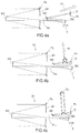
- the detector D remains stationary and the means for changing the optical path comprise two roof-shaped mirrors T 1 , T 2 (i.e. two mirrors having two faces at about 90° to each other) located between the third mirror M 3 and the detector D, and means 10 ′ for translating one of the two roof-shaped mirrors, T 2 in the example, the other remaining stationary, linearly along an axis that is not parallel to the optical axis, so as to make the optical path change.
- the sides of the “roof” of T 1 which preferably have a slope of 45°, are not necessarily parallel to those of T 2 .
- FIG. 4 b illustrates a first position of the roof-shaped mirror T 2 corresponding to a first position of the mirror M 3 (short focal length)
- FIG. 4 c illustrates a second position of the roof-shaped mirror T 2 corresponding to a second position of the mirror M3 (longer focal length).
- a planar mirror M 0 allows the beam to be folded in order to increase the overall compactness of the optical system and/or to solve problems with bulk.
- a third variant which is illustrated in FIG. 4 d , is particularly suitable when the telescope is bifocal, i.e. it has only two focal lengths, the focal length fmin and the focal length fmax.
- the light beam corresponding to operation at fmin is in dark grey, and the light beam corresponding to operation at fmax is in lighter grey.
- the means for changing the optical path comprise stationary conventional mirrors Mf, Mf′ and Mf′′ and at least one retractable conventional mirror Mesc.
- the mirror Mf is placed on the optical paths of the two beams.
- the retractable mirror is retracted when the telescope is working at fmin and is positioned on the optical path of the beam when the telescope is working at fmax.
- the fold mirrors Mf′ and Mf′′ positioned on the optical path of the beam reflected by Mesc allow a focal plane PFmax to be obtained in the same location as PFmin, where the detector D is positioned.
- initial parameters which are compatible both with the minimum focal length fmin and the maximum focal length fmax are determined, for the first, second and third mirrors, with a known prior-art ray-tracing software package.
- the starting point therefore consists of the values: R 1 , R 2 _fmax, R 2 _fmin, R 3 _fmax, R 3 _fmin, C 1 _fmax, C 1 _fmin, C 2 _fmax, C 2 _fmin, C 3 _fmax, C 3 _fmin.
- the next stage of the optimization consists in constraining the radii of curvature and the conicities for the 2 extreme focal lengths fmin and fmax to be identical.
- the optimization is carried out in a conventional way using ray-tracing software packages (CodeV, Zemax, Oslo, etc.). These software packages are based on the principle of minimization of an error function.
- the error function includes the image quality in the focal plane and the constraint of the focal lengths fmin and fmax.
- the initial parameters are determined:
- the preset criterion for example consists in minimizing a wavefront error or WFE averaged over a plurality of points of the field, this type of criterion being well known in the art. Typically, it is sought to minimize the root-mean-square value or RMS WFE.
- An illustrative example is a two-focal-length telescope with:
- Diameter of the mirror M1 1.1 m
- the step of determining the initial parameters via a first optimization such as described above results in an initial telescope configuration in which the initial parameters have the following values:
- FIGS. 5 a and 5 b illustrate the aberrations present in the focal plane P F (positon of the detector) for a two-focal-length telescope the three aspherical mirrors M 1 , M 2 and M 3 of which have initial parameters obtained by solving the Korsch equations in the way explained above.
- FIG. 5 a illustrates the aberrations for the maximum focal length fmax, and FIG. 5 b for the minimum focal length fmin.
- defocus corresponds to Z 4 , astigmatism to Z 5 and Z 6 (Z 5 / 6 ), coma to Z 7 and Z 8 (Z 7 / 8 ) and spherical aberration (of the first order) to Z 9 .
- radial astigmatism astigmatism for which the tangential focal point is located before the sagittal focal point. Below, this astigmatism will be considered by convention to be positive and will be denoted A + ;
- tangential astigmatism astigmatism for which the sagittal focal point is located before the tangential focal point. Below, this astigmatism will be considered by convention to be negative and will be denoted A ⁇ ;
- “external” coma coma for which the shape of the image spot of a point source is a “comet” the tail (i.e. the widest portion) of which is directed away from the optical axis. It is a question of the coma created by a bifocal lens. Below, this coma will be considered by convention to be positive and will be denoted C + ;
- internal coma coma for which the shape of the image spot of a point source is a “comet” the tail of which is directed toward the optical axis. Below, this coma will be considered by convention to be negative and will be denoted C ⁇ .
- the Korsch telescope 30 according to the invention that is illustrated in FIG. 7 is based on a telescope 20 , such as illustrated in FIGS. 2 to 4 , comprising three mirrors M 1 , M 2 and M 3 such as described above, and a first detector D placed in a first focal plane P F (the first detector and the first focal plane are denoted D and P F respectively because a second detector and a second focal plane will be introduced further on in a variant of the invention).
- the telescope 30 according to the invention furthermore comprises a plurality of aspherical optical components CAi (i index comprised between 1 and n) respectively associated with the plurality of focal lengths fi, and respectively placed in a plurality of positions PCAi located between the first position P 1 of the exit pupil PS 1 and the second position P 2 of the exit pupil PS 2 . It is between these two positions that the size of the aspherical components is minimized.
- CAi aspherical optical components
- PCAi located between the first position P 1 of the exit pupil PS 1 and the second position P 2 of the exit pupil PS 2 . It is between these two positions that the size of the aspherical components is minimized.
- the role of these aspherical components is to compensate for the aberrations of the system, focal length by focal length, and the way in which they are calculated is described below.
- the respective positions of the aspherical components are separated from one another by 50 mm at most and preferably at most 20 mm. This makes the optimization calculations described below easier.
- the telescope 30 may comprise a plurality of n focal lengths with n>2, or only two focal lengths fmin and fmax (bifocal telescope).
- the telescope 30 furthermore comprises means 50 for changing the optical path, which means are placed between the aspherical components CAi and the first detector D and configured so that the first detector remains positioned in the first focal plane of the telescope.
- the means 50 are typically the means 10 described with reference to FIG. 4 a , or the assembly [T 1 , T 2 , 10 ′] described with reference to FIGS. 4 b and 4 c , or an assembly comprising stationary mirrors and at least one retractable mirror, such as for example the assembly [M 0 esc, Mf′, Mf′′] described with reference to FIG. 4 d.
- Each aspherical component CAi is placed on an optical path of a beam corresponding to the associated focal length fi when the telescope is working at said associated focal length fi, and off the optical path associated with another focal length when the telescope is working at this other focal length.
- a given aspherical component CAi 0 is “seen” (reflects or is passed through) by the light beam passing through the telescope only when the telescope is working at the corresponding focal length fi 0 .
- At least one aspherical component is retractable, via an ad hoc mechanism, so as to be placed on the optical path of the beam corresponding to said associated focal length when the telescope is working at this associated focal length, and off the optical path associated with this working focal length when the telescope is working at one of the other focal lengths.
- the aspherical components CAi are all retractable aspherical mirrors MAi, such as illustrated in FIG. 8 . They are placed on the optical path common to all the focal lengths, and positioned or not on the optical path depending on the focal length used.
- the simplest solution in terms of manufacture and control is for all of the retractable mirrors to be mounted on a single moving mechanism 80 .
- the positions of the retractable mirrors PCAi are then substantially identical, to within 10 mm, or even 5 mm.
- an example mechanism is a bush wheel, such as illustrated in FIG. 8 .
- the means 50 allowing the first detector D to be positioned in the first focal plane P F are for example roof-shaped mirrors with a translating mechanism 10 ′ such as described with reference to FIGS. 4 b and 4 c.
- a translating mechanism 90 For a two-focal-length telescope, it is possible to use a translating mechanism 90 to position MA 1 or MA 2 on the optical-beam path common to the two focal lengths, such as illustrated in FIG. 9 .
- the retractable mirror M 0 esc When the telescope 30 is working with the long focal length fmax (dark grey), the retractable mirror M 0 esc is positioned on the optical path, the stationary mirrors Mf′ and Mf′′ redirecting the beam to the first detector D, as described with reference to FIG. 4 d and FIG. 9 .
- the mirror M 0 esc When the telescope is working with the focal length fmin (light grey), the mirror M 0 esc is retracted with a mechanism 95 . The complex mechanism for moving the roof-shaped mirrors is thus avoided.
- a holder 80 with which the switch from one aspherical mirror to the other is achieved by flipping about an axis of rotation, i.e. what is referred to as a “flip/flop” mechanism.
- this first variant telescope 30 composed uniquely of mirrors is that its operation is independent of wavelength since the mirrors do not produce chromatic aberration.
- the spectral band of operation is then set by the nature of the reflective material of the mirrors and the spectral band of sensitivity of the first detector.
- At least one aspherical component is an aspherical plate LA working in transmission.
- An example for a two-focal-length telescope is illustrated in FIG. 10 .
- the retractable aspherical mirror MA is positioned on the path of the beams when the telescope is working at the focal length fmax, and is retracted (via a mechanism 105 ) when the telescope is working at the focal length fmin, the aspherical plate LA then being located on the path of the beam.
- the moving mechanism 95 is thus no longer needed and can be omitted.
- the exit pupil does not remain stationary and depends on the focal length of the zoom.
- the exit pupil moves (order of magnitude ⁇ 200 mm) depending on the chosen focal length.
- the aspherical mirrors CAi therefore work in the field. This has a very large impact on the aberrations introduced into the system by the aspherical mirrors.
- a beam corresponding to a point of the field illuminates this mirror in its entirety, and therefore the reflected beam will be impacted by spherical aberration if the mirror in question has spherical aberration.
- each beam corresponding to a point of the field illuminates different zones of the mirror (not the entirety thereof).
- the wavefronts reflected by the different zones of the mirror will therefore have different aberrations.
- introducing spherical aberration into the CAi the positions of which do not coincide with the exit pupil introduces, into the telescope, astigmatism and coma in much larger proportions than spherical aberration.
- FIG. 11 illustrates, for the initial system, the aberrations that result following the introduction of spherical aberration Z 9 CA into an aspherical component (Z 9 CA >0 in FIG. 11 a and Z 9 CA ⁇ 0 in FIG. 11 b ) as a function of its relative position with respect to the effective exit pupil PS, when it is located downstream of PS with respect to the mirror M 3 .
- FIGS. 12 a and 12 b illustrate, for the initial system, the aberrations that result following the introduction of spherical aberration Z 9 CA into an aspherical component (with Z 9 CA >0 in FIG. 12 a and Z 9 CA ⁇ 0 in FIG. 12 b ) as a function of its relative position with respect to the effective exit pupil PS, when it is located upstream of PS with respect to the mirror M 3 .
- the aspherical component being placed between P 1 and P 2 , it is located as shown in FIGS. 11 a and 11 b for the max focal length (downstream of PS 2 with respect to M 3 ) and as shown in FIGS. 12 a and 12 b for the min focal length (upstream of PS 1 with respect to M 3 ).
- FIGS. 11 a -11 b and 12 a -12 b it may be seen from FIGS. 11 a -11 b and 12 a -12 b that the introduction of spherical aberration Z 9 CA into an aspherical component CA introduces aberrations such as astigmatism and coma into the telescope. This means that an aspherical component may compensate for aberrations that are the inverse of those created by Z 9 CA .
- Z 9 CA >0 allows A + and C to be corrected for fmax and A + and C ⁇ to be corrected for fmin.
- This correctional capacity is incompatible with the initial system the aberrations to be corrected of which are illustrated in FIGS. 5 a and 5 b.
- the third mirror M 3 has a new conicity c′ 3 determined from the initial conicity c 3 (calculated from the Korsch equations in the first optimization in the way explained above).
- the new conicity c′ 3 is determined so that the three-aspherical-mirror anastigmat telescope has, in the absence of an aspherical component, and for the minimum and maximum focal lengths, aberrations that are compensable by addition of this aspherical component.
- the compensable aberrations are astigmatism and coma.
- it is sought to obtain a M 1 /M 2 /M 3 telescope configuration (without CAi) having the following compensable aberrations:
- the new conicity c′ 3 is therefore determined so as to modify the sign of the telescope astigmatism in the absence of an aspherical component, for the minimum focal length, i.e. so as to convert the negative astigmatism of the system into a positive astigmatism for the minimum focal length.
- FIG. 13 illustrates the variation in the average value of the ⁇ Z 5 / 6 > astigmatism of the 3-mirror telescope (without the CAi) in arbitrary units, for the min focal length (curve 11 ) and max focal length (curve 12 ), as a function of the conicity value of M 3 .
- the initial conicity c 3 ⁇ 0.61
- the astigmatism is positive for fmax and negative for fmin.
- a second optimization of image quality is then carried out, starting with the value c′3inf, in order to determine the new conicity c′ 3 , the position PCAi of each CAi and the form of each surface Si that allows the best image quality to be obtained according to the preset criterion.
- PCA1 and S1 and PCAn and Sn are calculated first and intermediate PCAi and Si are deduced from these values.
- the form of the surface Si of a CAi suitable for compensating for the aberrations of the optical system of focal length fi comprising M 1 , M 2 , and M 3 of conicity c′ 3 must comprise first-order spherical aberration Z 9 CA and more particularly positive Z 9 CA .
- the exact value of the new conicity c′ 3 , the positions PCAi and where appropriate the median position Pm of the CAi, and the forms S1 for fmin, Sn for fmax, and Si for fi, are determined via a second optimization of the optical paths in the instrument, so as to correct the aberrations of the 3-mirror telescope having a new conicity c′ 3 and to optimize image quality in the first focal plane of the telescope according to the preset criterion, typically the minimization of a wavefront error WFE.
- the modification of the conicity of M 3 makes it possible to invert the sign of the astigmatism at the min focal length, and thus to introduce aberrations into the optical system such that the aberrations resulting from the optical system may be compensated for by an aspherical component positioned in the interpupil zone.
- the new value c′ 3 of the conicity of M 3 allows positive astigmatisms to be obtained for all the focal lengths and comas of opposite sign to be obtained for the extreme focal lengths.
- the new conicity c′ 3 differs by about 20% from the initial conicity c 3 (equal to ⁇ 0.61). Preferably, the new conicity c′ 3 differs from the initial conicity c 3 by more than 5% and by less than 30%.
- FIG. 15 illustrates the variation in the root-mean-square value of the wavefront error RMS WFE as a function of the conicity value of M 3 , for the min focal length (curve 15) and the max focal length (curve 16). It may be seen that the initial conicity c 3 corresponded to the optimized value of image quality, a new conicity value c′ 3 higher than ⁇ 0.56 leading to an increase in WFE, i.e. to a decrease in image quality.
- the change in value of the conicity of M 3 is not in response to a need for image quality, but allows aberrations that are compensable by a CA to be obtained. Image quality is no longer optimum with the aim of allowing aberrations to be corrected.
- Z 9 CA Introducing spherical aberration Z 9 CA with each aspherical component CAi allows the Z 7 / 8 (coma) and Z 5 / 6 (astigmatism) of the system to be greatly decreased, but does not decrease defocus Z 4 .
- Z 9 CA will also lead to an increase in the Z 4 of the telescope as illustrated in FIG. 17 , which illustrates the variation in the average defocus ⁇ Z 4 > of the system (3-mirror telescope without CAi) as a function of the value of the conicity of M 3 , for the min focal length (curve 17) and the max focal length (curve 18): it may be seen that defocus Z 4 increases substantially, in particular for the min focal length.
- Z 4 CA also allows the coma and astigmatism values to be balanced, i.e. to bring the values of the respective coefficients close together, thereby allowing the compensation by the Z 9 CA to be improved.
- the final value of c′ 3 , the final Z 9 CA (i) and the final Z 4 CA(i) to be used for S1, Sn and all the intermediate Si, and the various positions (or the single position Pm) of the CAi are determined via a second optimization.
- FIGS. 16 a and 16 b illustrate the various aberrations in the first focal plane of a telescope 30 according to the invention, the mirror M 3 of the telescope having a new conicity c′ 3 and the CAi having a single median position Pm and optimized values of Z 9 CA (1) and Z 9 CA (n) and of Z 4 CA (1) and Z 4 CA (n) (namely Z 9 CA/max and Z 9 CA/min ; Z 4 CAmax and Z 4 CA/min ).
- FIG. 16 a illustrates the various aberrations for the max focal length and FIG. 16 b for the min focal length.
- the form of the surface Sn for the max focal length therefore comprises Z 9 CA (n) and Z 4 CA (n).
- the form of the surface S 1 for the min focal length therefore comprises Z 9 CA (1) and Z 4 CA (1).
- the CAi are all positioned 110 mm after PS 1 and 140 mm before PS 2 .
- FIGS. 16 a and 16 b show the change of scale
- the conicities of the mirrors M 2 and M 1 of the telescope 30 according to the invention are modified slightly.
- the performance of the telescope may be further improved, the Z 7 / 8 and Z 9 being compensated for only by the Z 9 CA .
- Modifying the conicity of M 2 allows exactly these two aberrations to be adjusted. However, this new conicity c′ 2 also introduces a large amount of Z 4 . This excess of Z 4 is counterbalanced by modifying the conicity of M 1 (new c′ 1 value), which also modifies the Z 9 .
- a new conicity c′ 1 is determined for the first mirror and a new conicity c′ 2 is determined for the second mirror from a first initial conicity c 1 of the first mirror and a second initial conicity c 2 of the second mirror, respectively, so as to further improve the image quality of the telescope according to the preset criterion.
- FIGS. 18 and 19 These modifications are illustrated in FIGS. 18 and 19 .
- FIG. 18 illustrates the variation in the main aberrations as a function of the value of the conicity of M 2 , for the min and max focal lengths
- FIG. 19 the variation in the main aberrations as a function of the value of the conicity of M 1 .
- a third optimization is used to determine the new conicity values c′ 2 and c′ 1 :
- Z 16 CA i.e. second-order spherical aberration, which influences Z 16 , Z 9 , Z 4 Z 5 / 6 and Z 7 / 8 and allows image quality to be further increased, is also added.
- FIGS. 20 a and 20 b illustrate the various aberrations in the first focal plane of a telescope 30 according to the invention, the mirrors M 1 , M 2 and M 3 of the telescope respectively having new conicities c′ 1 , c′ 2 and c′ 3 and CA 1 and CAn having a median position Pm and optimized values of Z 9 CA , Z 4 CA and Z 16 CA .
- FIG. 20 a illustrates the various aberrations for the max focal length and FIG. 20 b for the min focal length.
- Each surface may be optimized via the parameters (R, k, A, B) or via the equivalent Zemicke coefficients Z 4 , Z 9 , Z 16 , depending on the chosen option of the software package used.
- FIGS. 20 a and 20 b show that the quality of the telescope is greatly improved.
- the obtained final image quality is compatible with the constraint of an RMS WFE ⁇ /15, which in the visible corresponds to a RMS WFE ⁇ 50 nm (see FIG. 22 below).
- the aspherical components CAi form an integral part of the optics of the instrument.
- the form Si of each CAi associated with the intermediate focal lengths is calculated from the form of the surfaces S 1 and Sn for the minimum a maximum focal lengths, respectively, in order to apply a suitable correction at each focal length.
- the telescope 30 according to the invention has an additional channel operating in a wavelength range that is different from the operating range of the main channel of the telescope, an example architecture of this type of telescope being illustrated in FIG. 21 .
- the main channel operates in a first wavelength range SB1, typically the visible between 400 and 800 nm, and the sensitivity of the first detector D is suitable for SB1.
- the additional channel operates in a second spectral band SB2 that is different from SB1, typically comprised in the infrared band.
- the aspherical components associated with the various focal lengths are preferably retractable mirrors MAi mounted on a single holder 80 .
- This holder furthermore has a neutral position in which no retractable mirror features on the optical path of the optical beam incident on the holder (simple “hole” with no optical function). The beam then passes through the holder 80 on a secondary optical path 86 .
- FIG. 22 For a two-focal-length telescope, an example embodiment of such a three-position holder 80 is illustrated in FIG. 22 . It has three positions, respectively obtained by pivoting around an axis of rotation 40 , the two aspherical mirrors MA 1 and MA 2 being mounted around a hollow structure. In a first position MA 1 reflects the incident beam, in a second position it is MA 2 that reflects the incident beam, and in a neutral third position the incident beam passes through the holder.
- Other designs are of course possible, such as a bush wheel.
- This multichannel telescope 30 furthermore comprises an optical device 85 placed on the secondary optical path 86 and configured to generate a second focal plane P′ F of the telescope, corresponding to a chosen focal length f′.
- the optical device 85 preferably works in transmission, so as to be compatible with a focal length f′ chosen to be very much smaller than fmin, typically 10 times smaller.
- the device 85 is furthermore configured to correct the compensable aberrations of the telescope and to optimize image quality in the second focal plane P′ F of the telescope according to the preset criterion. It has the same compensating function as the aspherical mirrors. It is typically a dioptric objective composed of a plurality of lenses. Because of the flexibility of the design, the lenses may be spherical while having a compensating function.
- a second detector D′ is placed in the second focal plane P′ F of the telescope, and is sensitive in the second spectral band SB2.
- a spectral filter is preferably placed on the secondary optical path, between the holder 80 and the second detector D′ in order to select the spectral band SB2.
- An example of an embodiment is a telescope having a two-focal-length main channel in the visible and a single-focal-length additional infrared channel.
- an infrared channel of lower resolution than the visible channel but of larger field, this being obtained with a focal length f that is shorter, typically by a factor of 10, than fmin.
- the focal length in the visible may be about ten meters and the IR focal length about one meter.
- the position of the mirror M 3 when operating in the infrared is preferably (but not necessarily) equal to one of the positions corresponding to the focal lengths of the visible main channel. At this focal length, a simultaneous visible/IR measurement is possible.
- the telescope according to the invention includes an aperture diaphragm placed in the interpupil zone and the aperture of which may be adjusted in order to keep a numerical aperture substantially constant when focal length changes.
- the invention relates to a method 60 for determining parameters of an anastigmat telescope, which method is illustrated in FIG. 23 .
- the telescope comprises:
- means 5 for moving the third mirror linearly along the optical axis O of the telescope so as to make the focal length of the telescope change to a plurality of focal lengths fi (i index from 1 to n) between a minimum focal length fmin and a maximum focal length fmax.
- the three mirrors M 1 , M 2 and M 3 are arranged so that the first mirror and the second mirror form from an object at infinity an intermediate image between the second mirror and the third mirror, the third mirror forming from this intermediate image a final image in the first focal plane of the telescope in which the first detector D is placed.
- the first, second and third mirrors are of a set form characterized by at least a conicity and a radius of curvature.
- the telescope has at the minimum focal length a first exit pupil PS 1 in a first position P 1
- the telescope has at the maximum focal length a second exit pupil PS 2 in a second position P 2 .
- the plurality of aspherical components CAi are respectively associated with the plurality of focal lengths fi, each aspherical component being placed on an optical path of a beam corresponding to said associated focal length when the telescope is working at said associated focal length, and off the optical path associated with another focal length when the telescope is working at said other focal length.
- the aspherical components are respectively placed in a plurality of positions PCAi located between the first and second position.
- the method 60 comprises a first step 100 in which values, termed initial values, are determined for the conicities and radii of curvature of the first, second and third mirrors of the telescope:
- a conicity value c′ 3 inf is determined for the third mirror, from the initial conicity c 3 of the third mirror, with which value the telescope has, in the absence of aspherical components and at the minimum and maximum focal lengths, aberrations that are compensable by the aspherical components CA 1 and CAn respectively associated with the focal lengths fmin and fmax.
- the form of each surface Si comprises at least first-order spherical aberration and defocus.
- the method 60 furthermore comprises a step 400 consisting in determining a new conicity c′ 1 for the first mirror and a new conicity c′ 2 for the second mirror M 2 , so as to further improve image quality according to the preset criterion.
- the method 60 also comprises a step 500 consisting in refining the surface Si of each aspherical component by furthermore incorporating a second-order spherical aberration so as to further improve image quality according to the preset criterion.
- the preset criterion consists in minimizing a wavefront error WFE.
- FIG. 24 illustrates the variation in the RMS WFE averaged over the various focal lengths at the end of each step of the method, i.e. as a function of the various modifications made to the optical system, for the example telescope configuration given above.
- the WFE obtained after the first optimization based on the Korsch equations is about 560 nm, incompatible with the RMS WFE constraint ⁇ 50 nm.
- the WFE is degraded (as yet no aspherical compensating components).
- the WFE is greatly improved to about 100 nm.
- the modification of the conicities of M 1 and M 2 allows the WFE to be decreased below about fifty nm, and the final optimization, introducing second-order spherical aberration, allows it to be further decreased to about ten nm.
Landscapes
- Physics & Mathematics (AREA)
- General Physics & Mathematics (AREA)
- Optics & Photonics (AREA)
- Astronomy & Astrophysics (AREA)
- Spectroscopy & Molecular Physics (AREA)
- Life Sciences & Earth Sciences (AREA)
- Sustainable Development (AREA)
- Telescopes (AREA)
- Lenses (AREA)
Applications Claiming Priority (4)
| Application Number | Priority Date | Filing Date | Title |
|---|---|---|---|
| FR1601770 | 2016-12-13 | ||
| FR1601770A FR3060135A1 (fr) | 2016-12-13 | 2016-12-13 | Telescope compact presentant une pluralite de focales compense par des composants optiques aspheriques |
| FR1700254A FR3060136B1 (fr) | 2016-12-13 | 2017-03-09 | Telescope compact presentant une pluralite de focales compense par des composants optiques aspheriques |
| FR1700254 | 2017-03-09 |
Publications (2)
| Publication Number | Publication Date |
|---|---|
| US20180164573A1 US20180164573A1 (en) | 2018-06-14 |
| US10866403B2 true US10866403B2 (en) | 2020-12-15 |
Family
ID=58737596
Family Applications (1)
| Application Number | Title | Priority Date | Filing Date |
|---|---|---|---|
| US15/840,555 Active 2039-02-16 US10866403B2 (en) | 2016-12-13 | 2017-12-13 | Compact telescope having a plurality of focal lengths and compensated by aspherical optical components |
Country Status (3)
| Country | Link |
|---|---|
| US (1) | US10866403B2 (fr) |
| ES (1) | ES2877682T3 (fr) |
| FR (2) | FR3060135A1 (fr) |
Families Citing this family (12)
| Publication number | Priority date | Publication date | Assignee | Title |
|---|---|---|---|---|
| FR3072784B1 (fr) | 2017-10-19 | 2019-11-15 | Thales | Telescope de type korsh ameliore |
| CN111487755B (zh) * | 2019-01-25 | 2021-06-25 | 清华大学 | 自由曲面离轴三反成像系统 |
| CN111487754B (zh) * | 2019-01-25 | 2021-04-23 | 清华大学 | 自由曲面离轴三反成像系统 |
| CN111487753B (zh) * | 2019-01-25 | 2021-06-01 | 清华大学 | 自由曲面离轴三反成像系统 |
| FR3101438B1 (fr) * | 2019-09-26 | 2023-01-13 | Thales Sa | Télescope de type Cassegrain à plan focal segmenté |
| CN111123503B (zh) * | 2020-02-28 | 2023-09-12 | 中国科学院上海技术物理研究所 | 一种同轴四镜折反射式低畸变望远光学系统 |
| EP4009107A1 (fr) * | 2020-12-01 | 2022-06-08 | ASML Netherlands B.V. | Procede et appareil d'imagerie d'un objet non stationnaire |
| CN113204113B (zh) * | 2021-05-20 | 2022-05-27 | 中国科学院长春光学精密机械与物理研究所 | 光学系统的自由曲面优化方法、装置和计算机存储介质 |
| CN114815202B (zh) * | 2022-04-11 | 2023-05-05 | 北京理工大学 | 一种大相对孔径离轴六反非轴向变焦成像光学系统 |
| DE102023120069B4 (de) | 2023-07-27 | 2025-02-06 | Fraunhofer-Gesellschaft zur Förderung der angewandten Forschung eingetragener Verein | Reflektives optisches System mit verstellbarer effektiver Brennweite sowie optischer Aufbau |
| WO2025090434A1 (fr) * | 2023-10-24 | 2025-05-01 | University Of Rochester | Télescope réfléchissant afocal à configurations multiples |
| CN117130172B (zh) * | 2023-10-25 | 2024-01-02 | 中国科学院长春光学精密机械与物理研究所 | 一种拼接式空间望远镜全局装调方法、装置、设备及介质 |
Citations (9)
| Publication number | Priority date | Publication date | Assignee | Title |
|---|---|---|---|---|
| US4101195A (en) * | 1977-07-29 | 1978-07-18 | Nasa | Anastigmatic three-mirror telescope |
| US4993818A (en) * | 1988-10-17 | 1991-02-19 | Hughes Aircraft Company | Continuous zoom all-reflective optical system |
| US5144476A (en) | 1989-04-24 | 1992-09-01 | Kebo Reynold S | All-reflective zoom optical system |
| US6084727A (en) | 1999-04-28 | 2000-07-04 | Raytheon Company | All-reflective field-switching optical imaging system |
| US6333811B1 (en) | 1994-07-28 | 2001-12-25 | The B. F. Goodrich Company | All-reflective zoom optical imaging system |
| US7292385B2 (en) * | 2004-09-20 | 2007-11-06 | Thales | Mirror with local deformation by thickness variation of an electro-active material controlled by electrical effect |
| US8534851B2 (en) * | 2010-07-20 | 2013-09-17 | Raytheon Company | Multiple path substantially symmetric three-mirror anastigmat |
| US8746884B2 (en) * | 2009-04-13 | 2014-06-10 | Canon Kabushiki Kaisha | Optical image acquisition apparatus having adaptive optics and control method for the same |
| US20140327898A1 (en) * | 2006-04-07 | 2014-11-06 | Carl Zeiss Smt Gmbh | Microlithography projection optical system and method for manufacturing a device |
-
2016
- 2016-12-13 FR FR1601770A patent/FR3060135A1/fr active Pending
-
2017
- 2017-03-09 FR FR1700254A patent/FR3060136B1/fr active Active
- 2017-12-04 ES ES17205097T patent/ES2877682T3/es active Active
- 2017-12-13 US US15/840,555 patent/US10866403B2/en active Active
Patent Citations (9)
| Publication number | Priority date | Publication date | Assignee | Title |
|---|---|---|---|---|
| US4101195A (en) * | 1977-07-29 | 1978-07-18 | Nasa | Anastigmatic three-mirror telescope |
| US4993818A (en) * | 1988-10-17 | 1991-02-19 | Hughes Aircraft Company | Continuous zoom all-reflective optical system |
| US5144476A (en) | 1989-04-24 | 1992-09-01 | Kebo Reynold S | All-reflective zoom optical system |
| US6333811B1 (en) | 1994-07-28 | 2001-12-25 | The B. F. Goodrich Company | All-reflective zoom optical imaging system |
| US6084727A (en) | 1999-04-28 | 2000-07-04 | Raytheon Company | All-reflective field-switching optical imaging system |
| US7292385B2 (en) * | 2004-09-20 | 2007-11-06 | Thales | Mirror with local deformation by thickness variation of an electro-active material controlled by electrical effect |
| US20140327898A1 (en) * | 2006-04-07 | 2014-11-06 | Carl Zeiss Smt Gmbh | Microlithography projection optical system and method for manufacturing a device |
| US8746884B2 (en) * | 2009-04-13 | 2014-06-10 | Canon Kabushiki Kaisha | Optical image acquisition apparatus having adaptive optics and control method for the same |
| US8534851B2 (en) * | 2010-07-20 | 2013-09-17 | Raytheon Company | Multiple path substantially symmetric three-mirror anastigmat |
Non-Patent Citations (4)
| Title |
|---|
| K. Seidl et al., "Wide field-of-view all-reflective objectives designed for multispectral image acquisition in photogrammetric applications," Optical Complex Systems, vol. 8172, 2011. |
| Korsch, "Reflective Optics", Chapter 10, pp. 261-264. |
| Z. Xin et al., "Three mirror anastigmatic zoom system using deformable mirrors," International Symposium on Photoelectronic Detection and Imaging 2011: Space Exploration Technologies and Applications, vol. 8196, No. 1, Jun. 9, 2011, pp. 1-8, XP060016106. |
| ZHAO XIN; XIE YONG-JUN: "Three mirror anastigmatic zoom system using deformable mirrors", INTERNATIONAL SYMPOSIUM ON PHOTOELECTRONIC DETECTION AND IMAGING 2011: SPACE EXPLORATION TECHNOLOGIES AND APPLICATIONS, SPIE, 1000 20TH ST. BELLINGHAM WA 98225-6705 USA, vol. 8196, no. 1, 9 June 2011 (2011-06-09), 1000 20th St. Bellingham WA 98225-6705 USA, pages 1 - 8, XP060016106, DOI: 10.1117/12.900730 |
Also Published As
| Publication number | Publication date |
|---|---|
| FR3060136B1 (fr) | 2019-05-17 |
| US20180164573A1 (en) | 2018-06-14 |
| FR3060135A1 (fr) | 2018-06-15 |
| FR3060136A1 (fr) | 2018-06-15 |
| ES2877682T3 (es) | 2021-11-17 |
Similar Documents
| Publication | Publication Date | Title |
|---|---|---|
| US10866403B2 (en) | Compact telescope having a plurality of focal lengths and compensated by aspherical optical components | |
| US10976537B2 (en) | Compact telescope having a plurality of focal lengths compensated for by a deformable mirror | |
| US9689744B2 (en) | Visible-infrared plane grating imaging spectrometer | |
| Wynne | Ritchey-Chretien telescopes and extended field systems | |
| US11086120B2 (en) | Bifocal anastigmatic telescope with five mirrors | |
| US11287635B2 (en) | Multi-channel folded optical system | |
| US8488237B2 (en) | Wide spectral coverage Ross corrected Cassegrain-like telescope | |
| US4479695A (en) | Afocal refractor telescopes | |
| Cui et al. | Introduction on Chinese 12m optical/infrared telescope (LOT) | |
| EP3336594A1 (fr) | Telescope compact presentant une pluralite de focales compense par des composants optiques aspheriques | |
| US10768045B1 (en) | Large format three-mirror dispersive spectrometer optics | |
| Byard et al. | MODS: optical design for a multi-object dual spectrograph | |
| US11287636B2 (en) | Bi-spectral anastigmat telescope | |
| Seppala | Improved optical design for the large synoptic survey telescope (lsst) | |
| CN117824833A (zh) | 一种用于积分视场光谱成像仪的分光成像方法 | |
| Saunders | Very fast transmissive spectrograph designs for highly multiplexed fiber spectroscopy | |
| Oliva et al. | Updated optical design and trade-off study for MOONS, the Multi-Object Optical and Near Infrared spectrometer for the VLT | |
| Rocha et al. | An aplanatic meniscus lens for correcting astigmatism in Ritchey-Chrétien telescopes | |
| Bernstein et al. | An optical design for a wide-field optical spectrograph for TMT | |
| GB2085184A (en) | Afocal dual magnification refractor telescopes | |
| US20240142790A1 (en) | Devices and methods for performing high-harmonic diffractive lens color compensation | |
| Marafatto et al. | Aligning a more than 100 degrees of freedom wavefront sensor | |
| US7336370B1 (en) | Optical nulling apparatus and method for testing an optical surface | |
| Lemaitre | Optical Design with the Schmidt Concept–Telescopes and Spectrographs | |
| Gillingham et al. | Optical Design for IRIS2: the AAT's next Infrared Spectrometer |
Legal Events
| Date | Code | Title | Description |
|---|---|---|---|
| FEPP | Fee payment procedure |
Free format text: ENTITY STATUS SET TO UNDISCOUNTED (ORIGINAL EVENT CODE: BIG.); ENTITY STATUS OF PATENT OWNER: LARGE ENTITY |
|
| STPP | Information on status: patent application and granting procedure in general |
Free format text: DOCKETED NEW CASE - READY FOR EXAMINATION |
|
| AS | Assignment |
Owner name: THALES, FRANCE Free format text: ASSIGNMENT OF ASSIGNORS INTEREST;ASSIGNOR:TETAZ, NICOLAS;REEL/FRAME:046747/0011 Effective date: 20180828 |
|
| STPP | Information on status: patent application and granting procedure in general |
Free format text: NON FINAL ACTION MAILED |
|
| STPP | Information on status: patent application and granting procedure in general |
Free format text: NOTICE OF ALLOWANCE MAILED -- APPLICATION RECEIVED IN OFFICE OF PUBLICATIONS |
|
| STPP | Information on status: patent application and granting procedure in general |
Free format text: PUBLICATIONS -- ISSUE FEE PAYMENT VERIFIED |
|
| STCF | Information on status: patent grant |
Free format text: PATENTED CASE |
|
| MAFP | Maintenance fee payment |
Free format text: PAYMENT OF MAINTENANCE FEE, 4TH YEAR, LARGE ENTITY (ORIGINAL EVENT CODE: M1551); ENTITY STATUS OF PATENT OWNER: LARGE ENTITY Year of fee payment: 4 |