US10897741B2 - Power sharing based on processing time related to carriers - Google Patents
Power sharing based on processing time related to carriers Download PDFInfo
- Publication number
- US10897741B2 US10897741B2 US16/609,201 US201816609201A US10897741B2 US 10897741 B2 US10897741 B2 US 10897741B2 US 201816609201 A US201816609201 A US 201816609201A US 10897741 B2 US10897741 B2 US 10897741B2
- Authority
- US
- United States
- Prior art keywords
- transmission
- power
- time point
- processing time
- carrier
- Prior art date
- Legal status (The legal status is an assumption and is not a legal conclusion. Google has not performed a legal analysis and makes no representation as to the accuracy of the status listed.)
- Active
Links
- 238000012545 processing Methods 0.000 title claims abstract description 63
- 239000000969 carrier Substances 0.000 title description 46
- 230000005540 biological transmission Effects 0.000 claims abstract description 229
- 238000000034 method Methods 0.000 claims abstract description 31
- 238000004891 communication Methods 0.000 claims abstract description 18
- 230000009977 dual effect Effects 0.000 claims abstract description 16
- 238000005516 engineering process Methods 0.000 claims abstract description 10
- 230000007774 longterm Effects 0.000 claims abstract description 6
- 230000015654 memory Effects 0.000 claims description 13
- 208000037918 transfusion-transmitted disease Diseases 0.000 description 20
- 230000006870 function Effects 0.000 description 14
- 230000000694 effects Effects 0.000 description 7
- 241000700159 Rattus Species 0.000 description 6
- 230000007246 mechanism Effects 0.000 description 6
- 230000011664 signaling Effects 0.000 description 6
- 238000013507 mapping Methods 0.000 description 5
- 238000010586 diagram Methods 0.000 description 3
- 239000011159 matrix material Substances 0.000 description 3
- 230000008569 process Effects 0.000 description 3
- 230000001360 synchronised effect Effects 0.000 description 3
- 230000001052 transient effect Effects 0.000 description 3
- 230000002776 aggregation Effects 0.000 description 2
- 238000004220 aggregation Methods 0.000 description 2
- 230000008901 benefit Effects 0.000 description 2
- 125000004122 cyclic group Chemical group 0.000 description 2
- 238000005259 measurement Methods 0.000 description 2
- 230000032258 transport Effects 0.000 description 2
- 101150071746 Pbsn gene Proteins 0.000 description 1
- 230000002411 adverse Effects 0.000 description 1
- 238000013475 authorization Methods 0.000 description 1
- 230000003139 buffering effect Effects 0.000 description 1
- 238000004364 calculation method Methods 0.000 description 1
- 230000006835 compression Effects 0.000 description 1
- 238000007906 compression Methods 0.000 description 1
- 238000013461 design Methods 0.000 description 1
- 238000009792 diffusion process Methods 0.000 description 1
- 238000005315 distribution function Methods 0.000 description 1
- 238000001914 filtration Methods 0.000 description 1
- 238000003780 insertion Methods 0.000 description 1
- 230000037431 insertion Effects 0.000 description 1
- 238000007689 inspection Methods 0.000 description 1
- 238000012423 maintenance Methods 0.000 description 1
- 230000010363 phase shift Effects 0.000 description 1
- 230000000153 supplemental effect Effects 0.000 description 1
- 238000012546 transfer Methods 0.000 description 1
- 238000012795 verification Methods 0.000 description 1
Images




Classifications
-
- H—ELECTRICITY
- H04—ELECTRIC COMMUNICATION TECHNIQUE
- H04W—WIRELESS COMMUNICATION NETWORKS
- H04W52/00—Power management, e.g. Transmission Power Control [TPC] or power classes
- H04W52/04—Transmission power control [TPC]
- H04W52/30—Transmission power control [TPC] using constraints in the total amount of available transmission power
- H04W52/34—TPC management, i.e. sharing limited amount of power among users or channels or data types, e.g. cell loading
-
- H—ELECTRICITY
- H04—ELECTRIC COMMUNICATION TECHNIQUE
- H04W—WIRELESS COMMUNICATION NETWORKS
- H04W52/00—Power management, e.g. Transmission Power Control [TPC] or power classes
- H04W52/04—Transmission power control [TPC]
- H04W52/38—TPC being performed in particular situations
-
- H—ELECTRICITY
- H04—ELECTRIC COMMUNICATION TECHNIQUE
- H04W—WIRELESS COMMUNICATION NETWORKS
- H04W52/00—Power management, e.g. Transmission Power Control [TPC] or power classes
- H04W52/04—Transmission power control [TPC]
- H04W52/06—TPC algorithms
- H04W52/14—Separate analysis of uplink or downlink
-
- H—ELECTRICITY
- H04—ELECTRIC COMMUNICATION TECHNIQUE
- H04W—WIRELESS COMMUNICATION NETWORKS
- H04W52/00—Power management, e.g. Transmission Power Control [TPC] or power classes
- H04W52/04—Transmission power control [TPC]
- H04W52/06—TPC algorithms
- H04W52/14—Separate analysis of uplink or downlink
- H04W52/146—Uplink power control
-
- H—ELECTRICITY
- H04—ELECTRIC COMMUNICATION TECHNIQUE
- H04W—WIRELESS COMMUNICATION NETWORKS
- H04W72/00—Local resource management
- H04W72/12—Wireless traffic scheduling
Definitions
- the present disclosure relates to wireless communication and, more particularly, to a method and apparatus for power sharing in new radio access technology (NR).
- NR new radio access technology
- 3rd generation partnership project (3GPP) long-term evolution (LTE) is a technology for enabling high-speed packet communications.
- 3GPP 3rd generation partnership project
- LTE long-term evolution
- Many schemes have been proposed for the LTE objective including those that aim to reduce user and provider costs, improve service quality, and expand and improve coverage and system capacity.
- the 3GPP LTE requires reduced cost per bit, increased service availability, flexible use of a frequency band, a simple structure, an open interface, and adequate power consumption of a terminal as an upper-level requirement.
- eMBB enhanced mobile broadband
- MTC machine type communication
- URLLC ultra-reliable and low latency communication
- UE service/user equipment
- a wavelength is short in a millimeter wave (mmW) so that a plurality of antennas may be installed at the same area.
- the wavelength is 1 cm at a 30 GHz band
- total 100 antenna elements may be installed in a secondary arrangement form at 0.5 ⁇ (wavelength) on a panel of 5 ⁇ 5 cm2. Accordingly, a plurality of antenna elements is used at the mmW band so that a beamforming gain is increased to increase coverage or a throughput.
- a transceiver is included to adjust transmission power and a phase by antenna element, an independent beamforming is possible by frequency resource.
- transceivers are installed at 100 antenna elements, respectively, the effectiveness is deteriorated in a cost side. Accordingly, it is considered that a plurality of antenna elements are mapped to one transceiver and a direction of a beam are adjusted to an analog phase shifter.
- Such an analog beamforming scheme can create only one beam direction so that a frequency selective beamforming cannot be performed.
- a hybrid beamforming having B transceivers having the number less than Q antenna elements in an intermediate form of digital beamforming and analog beamforming may be considered.
- the number of direction of the beam capable of being simultaneously transmitted is changed according to a connection scheme of B transceivers and Q antenna elements, the number of direction of the beam is limited to less than B.
- a structure of a physical channel and/or related characteristics of NR may be different from those of an existing LTE.
- various schemes may be suggested.
- the present disclosure provides a method and apparatus for power sharing in new radio access technology (NR).
- NR new radio access technology
- the present disclosure discusses a mechanism for power sharing between carriers when a long-term evolution (LTE) carrier and an NR carrier and/or NR carriers are aggregated with carrier aggregation (CA) or dual connectivity (DC).
- LTE long-term evolution
- CA carrier aggregation
- DC dual connectivity
- a method for a user equipment (UE) to control power in a wireless communication system includes determining whether or not uplink (UL) transmission is performed at a specific time point in a first carrier having a first processing time, and when it is determined that the UL transmission is not performed at the specific time point in the first carrier, determining power for the UL transmission at the specific time point in a second carrier having a second processing time shorter than the first processing time, based on a guaranteed power for the first carrier.
- UL uplink
- a user equipment (UE) in a wireless communication system includes a memory, a transceiver, and a processor connected to the memory and the transceiver.
- the processor is configured to determine whether or not uplink (UL) transmission is performed at a specific time point in a first carrier having a first processing time, and when it is determined that the UL transmission is not performed at the specific time point in the first carrier, determine power for the UL transmission at the specific time point in a second carrier having a second processing time shorter than the first processing time, based on a guaranteed power for the first carrier.
- UL uplink
- FIG. 1 shows a NG-RAN architecture.
- FIG. 2 shows an example of a subframe structure in an NR.
- FIG. 3 shows EN-DC architecture
- FIG. 4 shows an example of CGs using different numerologies according to an embodiment of the present disclosure.
- FIG. 5 shows an example of CGs using different numerologies and different TAs according to an embodiment of the present disclosure.
- FIG. 6 shows an example of CGs using the same numerology and different TAs according to an embodiment of the present disclosure.
- FIG. 7 shows an example of power sharing according to an embodiment of the present disclosure.
- FIG. 8 shows another example of power sharing according to an embodiment of the present disclosure.
- FIG. 9 shows an example of CGs using different numerologies according to an embodiment of the present disclosure.
- FIG. 10 shows an example of allocating power first to early transmission according to an embodiment of the present disclosure.
- FIG. 11 shows another example of power sharing according to an embodiment of the present disclosure.
- FIG. 12 shows another example of power sharing according to an embodiment of the present disclosure.
- FIG. 13 shows another example of power sharing according to an embodiment of the present disclosure.
- FIG. 14 shows another example of power sharing according to an embodiment of the present disclosure.
- FIG. 15 shows the multiplexing of different TTIs and different numerologies according to an embodiment of the present disclosure.
- FIG. 16 shows a method for UE to control power according to an embodiment of the present disclosure.
- FIG. 17 shows a wireless communication system implemented according to an embodiment of the present disclosure.
- FIG. 18 shows a processor of a UE shown in FIG. 17 .
- 3rd generation partnership project (3GPP) long-term evolution (LTE)/LTE-A(advanced) or institute of electrical and electronics engineers (IEEE) having the same characteristic to be described below.
- 3GPP 3rd generation partnership project
- LTE long-term evolution
- LTE-A(advanced) institute of electrical and electronics engineers
- a 5G system is a 3GPP system including a 5G access network (AN), a 5G core network (CN) and user equipment (UE).
- the UE may be called other terms such as a mobile station (MS), a user terminal (UT), a subscriber station (SS), or a wireless device.
- a 5G AN is an access network including a non-3GPP access network and/or a new generation radio access network (NG-RAN) connected to the 5G CN.
- the NG-RAN is a wireless access network having a common characteristic connected to the 5G CN and for supporting at least one of following options.
- the NR is an anchor having E-UTRA extension.
- An E-UTRA is an anchor having NR extension.
- FIG. 1 shows a NG-RAN architecture.
- the NG-RAN includes at least one NG-RAN node.
- the NG-RAN node includes at least one gNB and/or at least one ng-eNB.
- a gNB/ng-eNB may be called a base station (BS) or an access point.
- a gNB provides an NR user plane and a control plane protocol termination toward the UE.
- An ng-eNB provides an E-UTRA user plane and a control plane protocol termination toward the UE.
- a gNB is connected with an ng-eNB through an Xn interface.
- the gNB and the ng-eNB are connected with the 5G CN through the NG interface.
- the gNB and the ng-eNB are connected with an access and mobility management function (AMF) through an NG-C interface, and are connected with a user plane function (UPF) through an NG-U interface.
- AMF access and mobility management function
- UPF user
- the gNB and/or ng-eNB host the following functions:
- the AMF hosts the following main functions:
- the UPF hosts the following main functions:
- the SMF hosts the following main functions:
- a plurality of orthogonal frequency division multiplexing (OFDM) numerologies may be supported.
- a plurality of numerologies may be mapped to different subcarrier spacings, respectively.
- a plurality of numerologies mapped to various subcarrier spacings of 15 kHz, 30 kHz, 60 kHz, 120 kHz, and 240 kHz may be supported.
- Downlink (DL) transmission and uplink (UL) transmission are configured in a frame having a length of 10 ms in the NR.
- One frame includes 10 subframes having a length of 1 ms.
- Each frame is divided into two half-frames having the same size.
- a half-frame 0 is configured by subframes 0-4.
- a half-frame 1 is configured by subframes 5-9.
- one frame group is included on UL and one frame group is included on DL.
- a slot is configured by each numerology in the subframe. For example, in a numerology mapped to a subcarrier spacing of 15 kHz, one subframe includes one slot. In a numerology mapped to a subcarrier spacing of 30 kHz, one subframe includes two slots. In a numerology mapped to a subcarrier spacing of 60 kHz, one subframe includes four slots. In a numerology mapped to a subcarrier spacing of 120 kHz, one subframe includes eight slots. In a numerology mapped to a subcarrier spacing of 240 kHz, one subframe includes 16 slots. The number of OFDM symbols per slot may maintain 14. A start point of a slot in the subframe may be arranged in a start point of an OFDM symbol in time.
- the OFDM symbol may be classified into a DL symbol, a UL symbol, or a flexible symbol.
- DL slot it may be assumed that DL transmission occurs in only a DL symbol or a flexible symbol.
- the UE may perform UL transmission in only the UL symbol or the flexible symbol.
- FIG. 2 shows an example of a subframe structure in an NR.
- the subframe structure of FIG. 2 may be used in a time division duplex (TDD) of the NR in order to minimize transmission delay of data.
- TDD time division duplex
- the subframe structure of FIG. 2 may be called a self-contained subframe structure.
- a first symbol of a subframe includes a DL control channel
- a final symbol includes a UE control channel.
- Symbols from a second symbol to a thirteenth symbol of the subframe may be used for DL data transmission or UL data transmission.
- the UE may receive DL data and transmit UL hybrid automatic repeat request (HARQ)-acknowledgement (ACK) in one subframe.
- HARQ hybrid automatic repeat request
- ACK acknowledgenowledgement
- a time taken for retransmission upon generation of data transmission error may be reduced. Accordingly, transfer delay of final data may be minimized.
- a base station and the UE may need a gap to convert a transmission mode into a reception mode or from the reception mode into the transmission mode.
- a partial symbol of a time point converted from DL to UL in the subframe structure may be configured as a guard period (GP).
- a physical channel in the NR is described.
- An antenna port is defined so that a channel on which a symbol is transported on the antenna port may be inferred from a channel on which a different symbol is transported on the same antenna port. If a large-scale characteristic of a channel to which a symbol is transferred on one antenna port may be inferred from a channel to which the symbols is transferred on a different antenna port, two antenna ports may have quasi co-located (QCL) relation to each other.
- the large-scale characteristic includes at least one of delay spread, Doppler diffusion, Doppler shift, average gain, average delay, and space reception parameter.
- a resource grid consisting of a plurality of subcarriers and a plurality of OFDM symbols is defined.
- the resource grid starts from a specific common resource block indicated by higher layer signaling.
- per antenna port and per numerology each element in the resource grid is called resource element (RE).
- the resource block (RB) is defined as 12 continuous subcarriers at a frequency domain.
- a reference RB starts from 0 at a frequency domain to be indexed in a gradually increased direction.
- a subframe 0 of the reference RB is common in all numerologies.
- a subcarrier of an index 0 of the reference RB functions as a common reference point with respect to another RB grid.
- a common RB starts from 0 at a frequency domain with respect to each numerology to be indexed in a gradually increased direction.
- a subcarrier having an index 0 of a common RB having index 0 corresponds to a subcarrier having index 0 of the reference RB in each numerology.
- a physical RB (PRB) and a virtual RB are defined in a bandwidth part (BWP), and starts from 0 in the BWP to be indexed in a gradually increased direction.
- BWP bandwidth part
- the BWP is defined as a continuous group of a selected PRB in a continuous group of common RBs in a given carrier and a given numerology.
- the UE may be configured with maximum 4 BWPs in DL, and only one DL BWP may be activated at a given time point. It is expected that the UE does not receive a physical downlink shared channel (PDSCH), a physical downlink control channel (PDCCH), a channel state information reference signal (CSI-RS) or a tracking RS (TRS) at an outside of an activated BWP. Further, the UE may be configured with maximum 4 BWPs in UL, and only one UL BWP may be activated at a given time point.
- PDSCH physical downlink shared channel
- PDCCH physical downlink control channel
- CSI-RS channel state information reference signal
- TRS tracking RS
- the UE When the UE is configured with a supplemental UL (SUL), the UE may be configured with maximum 4 BWPs in SUL, and only one UL BWP may be activated at a given time point.
- the UE cannot transmit a physical uplink shared channel (PUSCH) or a physical uplink control channel (PUCCH) at an outside of an activated BWP.
- PUSCH physical uplink shared channel
- PUCCH physical uplink control channel
- a closed loop demodulation RS (DM-RS) based spatial multiplexing is supported for a PDSCH.
- DM-RS closed loop demodulation RS
- Maximum 8 and 12 orthogonal DL DM-RS ports support type 1 and type 2 DM-RSs, respectively.
- Maximum 8 orthogonal DL DM-RS ports are supported per UE with respect to single-user multiple-input multiple-output (SU-MIMO).
- Maximum 4 DL DM-RS ports per UE are supported with respect to multi-user MIMO (MU-MIMO).
- the number of SU-MIMO code-words is 1 with respect to 1-4 layer transmission and 2 with respect to 5-8 layer transmission.
- the DM-RS and a corresponding PDSCH are transmitted using the same pre-coding matrix, and the UE does not need to know a pre-coding matrix in order to demodulate transmission.
- a transmitter may use different pre-coder matrixes with respect to different parts of a transmission bandwidth that results in a frequency selective pre-coding. Further, the UE may assume that the same pre-coding matrix is used through a group of PRBs called pre-coding RB group.
- DL physical layer processing of a transmission channel is configured by following steps:
- the UE may assume that at least one symbol having a DM-RS is included in each layer in which a PDSCH is transmitted to the UE.
- the number of DM-RS symbols and resource element mapping are configured by a higher layer.
- a TRS may be transmitted on an additional symbol in order to assist receiver phase track.
- the PDCCH is used to schedule DL transmission on the PDSCH and UL transmission on the PUSCH.
- Downlink control information (DCI) on the PDCCH include following information.
- a control channel is formed by a group of control channel elements, and each control channel element consists of a set of resource element groups. Different numbers of control channel elements are collected so that different code rates with respect to the control channel are configured. Polar coding is used for the PDCCH. Each resource element group transporting the PDCCH transports a DM-RS thereof. QPSK modulation is used for the PDCCH.
- NG-RAN supports multi-RAT dual connectivity configured so that a UE in the RRC_CONNECTED state with multiple RX/TX may use radio resources provided by two separate schedulers.
- Multi-RAT dual connectivity is generalization of the E-UTRA dual connectivity. Two separate schedulers are located at two different NG-RAN nodes connected to each other through a non-ideal backhaul. One of the two different NG-RAN nodes performs the role of a master node (MN), and the other one performs the role of a secondary node (SN). In other words, one scheduler is located at the MN while the other scheduler is located at the SN.
- MN master node
- SN secondary node
- the two different NG-RAN nodes provide either the E-UTRA connectivity (when the NG-RAN node is an ng-eNB) or NR connectivity (when the NG-RAN node is a gNB).
- the ng-eNB is a node that provides the NR user plane and control plane protocol termination toward a UE and operates as an SN in the E-UTRAN-NR dual connectivity (EN-DC).
- the gNB is a node that provides the E-UTRA user plane and control plane protocol termination toward a UE and is connected to 5G CN through an NG interface.
- the MN and SN are connected to each other through a network interface, and at least the MN is connected to the core network.
- FIG. 3 shows EN-DC architecture.
- the E-UTRAN supports multi-RAT dual connectivity through EN-DC, where a UE is connected to one eNB operating as an MN and one en-gNB operating as an SN.
- An eNB is connected to EPC through S1 interface and connected to en-gNB through X2 interface.
- the en-gNB may be connected to the EPC through S1-U interface and connected to a different en-gNB through X2-U interface.
- the 5G CN also supports multi-RAT dual connectivity.
- An NG-RAN supports NG-RAN E-UTRA-NR dual connectivity (NGEN-DC), where a UE is connected to one ng-eNB operating as an MN and one gNB operating as an SN.
- the ng-eNB is connected to the 5G CN, and the gNB is connected to the ng-eNB through Xn interface.
- the NG-RAN supports NR-E-UTRA dual connectivity (NE-DC), where a UE is connected to one gNB operating as an MN and one ng-eNB operating as an SN.
- the gNB is connected to the 5G CN, and ng-eNB is connected to the gNB through Xn interface.
- CA carrier aggregation
- DC DC
- NR carriers may use different TTI lengths and use dynamic HARQ timing for various channels. For example, the timing between PDSCH and PUCCH and the timing between PDCCH and PUSCH may be dynamically indicated. Also, in NR, the timing itself may be very short. Thus, PDSCH and PUCCH may be transmitted in the same slot, and PDCCH and PUSCH may be transmitted in the same slot. This corresponds to the self-contained subframe described in FIG. 2 .
- the present disclosure proposes a method for dynamically sharing power between carriers. According to the present disclosure, adverse effects on each carrier due to unknown scheduling/power information of other carriers may be minimized.
- CG carrier groups
- each group may include carriers for only one RAT.
- a first CG may include LTE carriers only (i.e., LTE-CG)
- a second CG may include NR carriers only (i.e., NR-CG).
- PUCCH groups there may be a plurality of PUCCH groups within one CG, and a PUCCH group may be defined as a group of carriers that shares the same carrier to transmit PUCCH.
- TTI timing advance
- scheduling interval scheduling unit
- Guaranteed power may be proposed to enable power sharing and minimize the effects of CGs on each other.
- the total power for UE shall be limited to the maximum UE power due to power limitations even when a plurality of carriers are aggregated.
- the total UE power may be shared between RATs regardless of RAT type.
- the guaranteed power for each CG may be shared so that the sum thereof does not exceed the maximum UE power.
- the guaranteed power between two CGs may be updated dynamically and/or semi-statically. Regardless of the state (e.g., DRX (discontinuous reception) or DL slot) of the other CG, each CG cannot use more than the configured guaranteed power. That is, from the point of view of each CG, guaranteed power may replace the maximum UE power, and every power calculation may be performed independently within a CG.
- state e.g., DRX (discontinuous reception) or DL slot
- each CG is permitted to use up to configured guaranteed power. However, if there is no possibility that UE will use the guaranteed power configured in one CG for a given amount of time from a specific time point, the other CG may borrow and use the corresponding power based on a semi-static configuration. Therefore, the other CG may use more than the configured guaranteed power.
- the semi-static configuration may include a semi-static resource pool configuration of sidelink, a semi-static resource configuration for UL, a grant-free semi-static resource configuration, a semi-static resource configuration for a physical random access channel (PRACH), a DRX configuration, and so on.
- a semi-static resource pool configuration of sidelink a semi-static resource configuration for UL
- a grant-free semi-static resource configuration a semi-static resource configuration for a physical random access channel (PRACH), a DRX configuration, and so on.
- a reference TDD configuration for LTE may be configured for UE through an upper layer.
- the UE may not perform UL transmission in a slot on the SCG of NR. If the UE can perform dynamic power sharing, UL transmission on the MCG overlapping UL transmission on the SCG may not be scheduled.
- FIG. 4 shows an example of CGs using different numerologies according to an embodiment of the present disclosure.
- CG 1 includes CC 1 and CC 2
- CC 1 is a CC that uses a numerology corresponding to a subcarrier spacing of 15 kHz
- CC 2 is a CC that uses a numerology corresponding to a subcarrier spacing of 30 kHz.
- CG 2 includes CC 3 and CC 4
- CC 3 is a CC that uses a numerology corresponding to a subcarrier spacing of 60 kHz
- CC 4 is a CC that uses a numerology corresponding to a subcarrier spacing of 240 kHz.
- a minimum latency required to know whether a UL transmission occurs at time point t 0 or not is about 1 slot based on scheduling intervals or the like.
- UE determines the power for UL transmission in the slot UL 1 of CC 1 , there is a need to take account of the potential power required for the slots UL 2 - 1 and UL 2 - 2 , the slots UL 3 - 1 , UL 3 - 2 , UL 3 - 3 , and UL 3 - 4 of CC 3 , and the UL slots of CC 4 .
- determining the power for UL transmission of CC 1 there is a need to take account of the potential power required for UL transmission in different carriers CC 2 , CC 3 , and CC 4 having a shorter scheduling interval (i.e., a longer subcarrier spacing). Since the minimum processing time of CC 1 is longer than the minimum processing time of the other CG, dynamic power sharing may not be used in determining the power for UL transmission of CC 1 . That is, if potential UL transmission is possible in CG 2 having a shorter scheduling interval, CG 1 cannot borrow the guaranteed power for CG 2 from CG 2 .
- determining the power for UL transmission of CC 3 if there is no UL transmission at t 0 , it can be ensured that there is no UL transmission in the slots UL 1 , UL 2 - 1 , and UL 2 - 2 of CG 1 .
- the scheduling interval of CG 1 is longer than the scheduling interval of CG 2 . That is, if a carrier or CG having a shorter minimum processing time or shorter scheduling interval has no scheduled UL transmission, they may use the guaranteed power for a carrier or CG having a longer minimum processing time or longer scheduling interval.
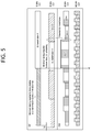
- FIG. 5 shows an example of CGs using different numerologies and different TAs according to an embodiment of the present disclosure.
- TA When determining whether there is a UL transmission in other carriers or CGs, TA, too, has to be taken into consideration.
- the guaranteed power for CG 1 may be used if there is no UL transmission in CG 1 .
- the UL transmission in the slot UL 3 - 1 spans a plurality of slots, there is a need to take account of potential UL transmission in the plurality of slots.
- UE Based on UL scheduling information at time point t 0 , UE is able to know that there is a scheduled UL transmission in the slot UL 2 - 2 overlapping the end of the slot UL 3 - 1 . This takes the TA of CC 2 into account (the slot UL 3 - 1 and the slot UL 2 - 2 do not overlap if the TA is not taken into account). Therefore, the UE cannot use the guaranteed power for CG 1 in determining the power for UL transmission in the slot UL 3 - 1 of CC 3 .
- a minimum latency required to know UL scheduling information may be shorter than the slot length.
- a minimum latency required to know UL scheduling information may be one or several OFDM symbols.
- FIG. 6 shows an example of CGs using the same numerology and different TAs according to an embodiment of the present disclosure.
- the slots between two carriers are not aligned but may only partially overlap even if the same numerology is used.
- the power for UL transmission in the slot k of CG 2 there is a need to take account of the power for UL transmission in the slots n and n+1 of CG 1 .
- the scheduling information in the slot n+1 and the power for UL transmission are not known at time point t 0 . Therefore, CG 2 cannot assume that there will be no UL transmission in CG 1 so long as CG 1 and CG 2 have a similar minimum processing time or similar minimum scheduling interval and there is potential UL transmission in the slot n+1 of CG 1 .
- power control mode 1 which is a power control mode for the synchronous mode of DC
- power control mode 1 which is a power control mode for the synchronous mode of DC
- the condition for using the configuration of power control mode 1 may vary depending on the numerology used by each CG or the slot length/scheduling interval length/TTI length.
- Power adjustment may not be performed on a carrier whose power adjustment part exceeds X % (e.g., 5%). For example, if a slot mapped at a subcarrier spacing of 15 kHz and another slot mapped at a subcarrier spacing of 15 kHz overlap with a timing difference of 33 us, the power for UL transmission in the slots mapped at a subcarrier spacing of 15 kHz may be adjusted. On the contrary, the power for UL transmission in a slot mapped at a subcarrier spacing of 60 kHz may not be adjusted.
- X % e.g., 5%
- TAGs TA groups
- the guaranteed power for the other CG may not be borrowed due to a potential transmission in the slot n+1. This means that power control mode 1 cannot be configured unless the two CGs are completely aligned. However, as long as UE ensures that there is no UL transmission in the slot n+1 due to a longer scheduling interval or DRX or configuration in CG 1 , the UE may borrow the guaranteed power for CG 1 when determining the power for UL transmission in CG 2 .
- FIG. 7 shows an example of power sharing according to an embodiment of the present disclosure.
- FIG. 7 illustrates that power adjustment is not performed on a carrier whose power adjustment part exceeds X %.
- a slot having a TTI of 14 OFDM symbols and a slot having an sTTI of 2 OFDM symbols partially overlap by having different TAs.
- the overlap is relatively small from the point of view of the slot having a TTI of 14 OFDM symbols, power adjustment may be performed in such a way that the maximum UE power is not exceeded.
- the overlap exceeds X %, the corresponding transmission may be omitted.
- the omission of UL transmission may be taken into consideration if at least discrete Fourier transform spread OFDM (DFT-s-OFDM) is used.
- DFT-s-OFDM discrete Fourier transform spread OFDM
- the same mechanism may be applied, or power adjustment at an OFDM symbol level may be taken into consideration.
- timing difference between two CGs is equal to or less than X % of a slot length corresponding to the largest subcarrier spacing used in the two CGs or the shortest scheduling interval length or shortest TTI length used in the two CGs, a partial overlap between the slot k and the slot n+1 may be handled by UE implementation.
- the guaranteed power for the other CG may not be borrowed due to a potential transmission in the slot n+1.
- the UE may borrow the guaranteed power for CG 1 when determining the power for UL transmission in CG 2 .
- the timing difference between different carriers or CGs having a short scheduling interval may have a larger effect compared to LTE.
- the timing difference may likewise have a larger effect on a numerology having a longer subcarrier spacing (e.g., 60/120/240 kHz).
- a sub CG for performing guaranteed power or power sharing may be configured within a CG to minimize the effect of the timing difference. That is, guaranteed power may be used between carriers having different TTIs, too. In this case, since there are two or more carriers, guaranteed power may be allocated to two or more groups.
- One sub CG may be configured to have the same numerology or the same scheduling interval.
- Priority on early transmission Power may be dynamically shared, and power may be allocated first for early transmission. However, there is a need to clearly define what early transmission is, considering processing time or the like.
- Priority on numerology having a short scheduling interval or a longer subcarrier spacing Power may be allocated first for UL transmission through a slot corresponding to a numerology having a short scheduling interval or a longer subcarrier spacing.
- a carrier or CG having a longer scheduling interval is not aware of a UL transmission in a carrier or CG having a short scheduling interval.
- the entire or some of a UL transmission in a carrier or CG having a longer scheduling interval may be omitted, or power adjustment may be required for an overlap.
- Guaranteed power may be allocated for each carrier or CG having a different scheduling interval or different numerology. If at least a potential UL transmission (i.e., overlapping transmission) is likely to occur, guaranteed power cannot be used for other carriers or CGs. Similarly to the allocation of guaranteed power between CGs, if UE ensures that there is no overlapping UL transmission by a semi-static configuration or dynamic signaling, the UE may use the unused power or guaranteed power for a certain carrier or CG for UL transmission of other carriers or CGs.
- FIG. 8 shows another example of power sharing according to an embodiment of the present disclosure.
- FIG. 8 illustrates a power sharing mechanism between carriers or CGs having different scheduling intervals or different numerologies according to an embodiment of the present disclosure.
- a UL transmission in CC 1 having a subcarrier spacing of 30 kHz and a UL transmission in CC 2 having a subcarrier spacing of 240 kHz partially overlap.
- FIG. 8 -( a ) illustrates a case that power is allocated first for early transmission as described above in (1). Since UL transmission in CC 1 is scheduled earlier than UL transmission in CC 2 , the power for UL transmission in CC 1 may be used as it is, and the maximum UE power minus the power for UL transmission in CC 1 may be used for UL transmission in CC 2 .
- FIG. 8 -( b ) illustrates a case that power is allocated first for UL transmission through a slot corresponding to a numerology having a short scheduling interval/s TTI or a longer subcarrier spacing s described above in (2). Since CC 2 has a longer subcarrier spacing than CC 1 , the power for UL transmission in CC 2 may be fully used, and the maximum UE power minus the power for UL transmission in CC 2 may be used for UL transmission in CC 1 .
- FIG. 8 -( c ) illustrates a case that the guaranteed power is allocated as described above in (3). Guaranteed power is allocated for UL transmission in CC 1 and UL transmission in CC 2 .
- FIG. 9 shows an example of CGs using different numerologies according to an embodiment of the present disclosure.
- MCG master cell group
- SCG secondary cell group
- the EN-DC described above in FIG. 3 may be an embodiment. Assuming that the power for UL transmission may be determined or changed one subframe or one slot before actual UL transmission, UE may have multiple time points at which the power for UL transmission has to be determined. Referring to FIG.
- t 0 is a time point at which the power for the subframe n of the MCG has to be determined
- t 0 is a time point at which the power for the slot m of the SCG has to be determined. Because the UE may not know information about the power in the slot m at time point t 0 , the UE cannot allocate the remaining power to the subframe n although the slot m precedes the subframe n. Therefore, UE cannot allocate remaining power to slot m at time point t 1 . From this point of view, early transmission may be defined based on power determination time and/or processing time, rather than by actual UL transmission time.
- FIG. 10 shows an example of allocating power first to early transmission according to an embodiment of the present disclosure.
- the time point t 0 for determining the power for the subframe n of the MCG is earlier than the time point t 1 for determining the power for the slot m of the SCG, the power for UL transmission of the MCG is allocated first.
- This problem may occur regardless of EN-DC or multi RAT DC. Also, a similar problem may occur to CA between NR carriers having different numerologies and/or different processing times. Generally, it is preferable that the UE allocates power first for early transmission in consideration of power determination time and/or processing time, in order to design a simpler power sharing mechanism.
- a particular carrier or CG does not use guaranteed power, there is an issue with the use of guaranteed power for the corresponding carrier or CG.
- the corresponding carrier or CG is in DRX state, or is configured with DL subframes/slots, or there is no UL scheduling, the particular carrier or CG do not use guaranteed power.
- semi-statically configured resources such as DRX or semi-statically configured DL subframes/slots will not be dynamically changed, and therefore the guaranteed power in the corresponding state may be used for UL transmission in other CGs.
- processing time should be further taken into consideration.
- a UL grant may be transmitted only several OFDM symbols before actual UL transmission. Therefore, the guaranteed power for UL transmission of a certain CG may be used for UL transmission of other CGs, only when UE ensures that there will be no UL transmission, based on that the certain CG will not have any UL grant in a semi-static configuration or the next overlapping UL part.
- FIG. 11 shows another example of power sharing according to an embodiment of the present disclosure.
- UE is able to know that there is no UL transmission in the subframe n+1 of the MCG at the time point t 1 for determining the power for the slot m+3 of the SCG.
- the UE can borrow the guaranteed power for the MCG for the UL transmission of the SCG.
- the UE cannot borrow the guaranteed power for the MCG for the UL transmission of the SCG, as long as there is UL transmission in the subframe n+2 of the MCG.
- FIG. 12 shows another example of power sharing according to an embodiment of the present disclosure.
- the power not used in the MCG may be used for UL transmission in the slot m+3 of the SCG, if the power requested for UL transmission in the subframe n+1 is smaller than the guaranteed power for the MCG. That is, if UE can look ahead due to the difference in processing time between CGs, the UE may use the power not used by any of the CGs for UL transmission in the other CG, regardless of synchronous/asynchronous DC.
- UE in the slot m of a certain CG is able to look ahead to the slot n of other CGs may be defined by any of the following:
- the UE may be defined as having the capability of looking ahead to the slot n when determining the power for UL transmission in the slot m.
- the UE may be defined as having the capability of looking ahead to the slot n when determining the power for UL transmission in the slot m.
- the UE may not be assumed to have any look-ahead capability, except information provided through a semi-static configuration in DC (at least EN-DC). That is, any dynamic power sharing based on dynamic scheduling may not be used.
- RAT or CG having small corresponding timing may be given priority.
- FIG. 13 shows another example of power sharing according to an embodiment of the present disclosure.
- FIG. 13 -( a ) illustrates a case that UE's look-ahead capability is defined based on the time point of transmission of scheduling information containing a TPC command described in above (1) in relation to look-ahead capability.
- a UL grant for the slot n of the MCG is transmitted at time point t 0
- a UL grant for the slot m of the SCG is transmitted at time point t 1 .
- the UE since t 0 is earlier than t 1 , the UE may be defined as having the capability of looking ahead to the slot n in determining the power for UL transmission in the slot m.
- the UE may use the remaining unused power for UL transmission in the slots m+1, m+2, and m+3 of the SCG because the requested power is smaller than the guaranteed power for the MCG.
- FIG. 13 -( b ) illustrates that UE's look-ahead capability is defined based on the time point of power allocation described in above (2) in relation to look-ahead capability.
- power allocation for the slot n of the MCG is performed at time point t 0
- power allocation for the slot m of the SCG is performed at time point t 1 .
- the UE since t 0 is later than t 1 , the UE may be defined as not having the capability of looking ahead to the slot n in determining the power for UL transmission in the slot m. That is, the UE cannot ensure that there is no UL transmission in the slot n of the MCG.
- the UE cannot use the remaining unused power for UL transmission in the slots m+1, m+2, and m+3 of the SCG.
- power adjustment is performed on the NR side but not on the LTE side.
- This offers two advantages: the first is that power adjustment should be performed on the NR side to minimize the effect on PCell coverage because an LTE cell is generally a PCell. And the second is that it is easier to implement power adjustment in terms of UE's processing because the processing time for LTE (e.g., 4 ms) is generally longer than the processing time for NR.
- FIG. 14 shows another example of power sharing according to an embodiment of the present disclosure.
- FIG. 14 illustrates that, in the DC between LTE and NR, the power for CG of LTE needs to be reduced depending on processing time in the case of dynamic power sharing, despite that NR is PCell. It is still very important to minimize the effect on PCell coverage even when NR is PCell. Therefore, in this case, power adjustment may be performed on the LTE side but not on the NR side. However, tighter processing time is required on the LTE side, for power adjustment on the LTE side.
- NR corresponds to MCG and LTE corresponds to SCG
- a UL grant for the slot n of the MCG is transmitted at time point to
- a UL grant for the subframe m of the SCG is transmitted at time point t 1 .
- the UE since t 1 is earlier than t 0 , the UE may be defined as not having the capability of looking ahead to the slot n in determining the power for UL transmission in the subframe m. Accordingly, if power adjustment is required in the subframe m of the SCG, power adjustment cannot be performed without tighter processing time.
- Power adjustment may be performed on the LTE side under the assumption that any PUSCH/PUCCH is not scheduled with processing time shorter than the processing time for LTE. That is, the network may ensure that a PUSCH/PUCCH shall be scheduled on the NR side earlier than the processing time for LTE (e.g., before 4 ms), and the UE may perform adjustment on the LTE side without tight processing time.
- Power adjustment may be performed for a later-scheduled UL transmission regardless of LTE/NR. That is, an earlier-scheduled UL transmission has priority in power allocation. For example, the power for UL transmission in LTE is protected because UL transmission in LTE is scheduled earlier than UL transmission in NR. Thus, there is no need for the UE to support tight processing time for dynamic power sharing.
- the power determined by each CG may exceed the power permitted for each CG. In this case, power adjustment or omission of channel/OFDM symbol transmission may be need.
- FIG. 15 shows the multiplexing of different TTIs and different numerologies according to an embodiment of the present disclosure. To explain the method for performing power sharing when power is limited, FIG. 15 may be taken into consideration.
- PUSCH refers to a UL data channel of a given numerology on a slot (e.g., 14 OFDM symbols).
- Short PUSCH refers to a UL data channel of a given numerology on an sTTI (e.g., 2 or 3 OFDM symbols in FIG. 15 ).
- PUCCH refers to a UL control channel of a given numerology on a slot (e.g., 14 OFDM symbols).
- Short PUCCH (sPUCCH) refers to a UL control channel of a given numerology on an sTTI (e.g., 2 or 3 OFDM symbols in FIG. 15 ).
- Different TTIs may be present within one carrier or CG, and/or a plurality of carriers or CGs may use different numerologies.
- power limitation may be required depending on a collision of a plurality of channels, and the following may be taken into consideration.
- Table 1 shows power limitations for collisions of PUSCH and PUCCH/sPUCCH.
- PUSCH (partially overlapping PUSCH (fully overlapping with PUCCH) with PUCCH) sPUCCH
- PUSCH may be If PUCCH and PUSCH have (e.g, 1/2 shortened. the same waveform and the OFDM If PUCCH and PUSCH have simultaneous configuration symbols) the same waveform and the of PUCCH and PUSCH is simultaneous configuration configured, PUCCH and of PUCCH and PUSCH is PUSCH may be configured, PUCCH and simultaneously transmitted. PUSCH may be Otherwise, PUCCH is simultaneously transmitted. piggybacked on PUSCH. Alternatively, if they partially overlap, PUCCH is piggybacked on PUSCH.
- PUCCH If PUCCH and PUSCH have If PUCCH and PUSCH have (e.g., 4 or the same waveform and the the same waveform and the more simultaneous configuration simultaneous configuration of OFDM of PUCCH and PUSCH is PUCCH and PUSCH is symbols) configured, PUCCH and configured, PUCCH and PUSCH may be PUSCH may be simultaneously transmitted. simultaneously transmitted. Alternatively, if they partially Otherwise, PUCCH is overlap, PUCCH is piggybacked on PUSCH. piggybacked on PUSCH or omitted.
- power control may be performed between carriers having different scheduling intervals. Unless two carriers have the same scheduling interval, the above-described (1) may be used.
- Table 2 shows collisions of different channels between a plurality of carriers.
- Case 1 Case 2
- Case 3 Case 3 will be described later.
- FIG. 16 shows a method for UE to control power according to an embodiment of the present disclosure. The foregoing description of the present disclosure may apply to this embodiment.
- step S 1600 UE determines whether uplink (UL) transmission is performed at a specific time point in a first carrier having a first processing time.
- step S 1610 When it is determined that UL transmission is not performed at the specific time point in the first carrier, the UE determines power for UL transmission at the specific time point in a second carrier having a second processing time shorter than the first processing time, based on guaranteed power for the first carrier.
- the power for UL transmission at the specific time point within the second carrier may be determined to be greater than the maximum UE power minus the guaranteed power for the first carrier. That is, the guaranteed power for the first carrier may be borrowed in determining the power for UL transmission at the specific time point within the second carrier.
- the first processing time may be either a first scheduling period, a first scheduling unit, or a first TTI.
- the second processing time may be either a second scheduling period, a second scheduling unit, or a second TTI.
- the first processing time may be one or more symbols or slots that are mapped to a first numerology having a first subcarrier spacing
- the second processing time may be one or more symbols or slots that are mapped to a second numerology having a second subcarrier spacing longer than the first subcarrier spacing.
- the first carrier may be a carrier of 3GPP LTE or NR
- the second carrier may be a carrier of the NR.
- the first carrier may be included in a first CG, and the second carrier may be included in a second carrier group.
- Whether UL transmission is performed at the specific time point in the first carrier or not may be determined at a first time point, and the power for UL transmission at the specific time point in the second carrier may be determined at a second time point equal to or later than the first time point. In this instance, whether UL transmission is performed at the specific time point in the first carrier or not may be determined depending on whether a UL grant is received at the first time point or not. Also, whether the UL transmission is performed at the specific time point in the first carrier or not may be determined based on different TAs the first and second carriers have.
- the power for UL transmission at the specific time point in the first carrier may be determined with higher priority than the power for UL transmission at the specific time point in the second carrier.
- FIG. 17 shows a wireless communication system implemented according to an embodiment of the present disclosure.
- a UE 1700 includes a processor 1710 , a memory 1720 , and a transceiver 1730 .
- the memory 1720 is connected to the processor 1710 and stores various information for running the processor 1710 .
- the transceiver 1730 is connected to the processor 1710 and sends a wireless signal to a network node 1800 or receives a wireless signal from the network node 1800 .
- the processor 1710 may be configured to implement the functions, processes, and/or methods explained in this disclosure. More specifically, the processor 1710 may perform the steps S 1600 and S 1610 in FIG. 16 .
- the network node 1800 includes a processor 1810 , a memory 1820 , and a transceiver 1830 .
- the memory 1820 is connected to the processor 1810 and stores various information for running the processor 1810 .
- the transceiver 1830 is connected to the processor 1810 and sends a wireless signal to the UE 1700 or receives a wireless signal from the UE 1700 .
- the processor 1810 may be configured to implement the functions, processes, and/or methods explained in this specification.
- the processors 1710 and 1810 may include application-specific integrated circuit (ASIC), other chipset, logic circuit and/or data processing device.
- the memories 1720 and 1820 may include read-only memory (ROM), random access memory (RAM), flash memory, memory card, storage medium and/or other storage device.
- the transceivers 1730 and 1830 may include baseband circuitry to process radio frequency signals.
- the techniques described herein can be implemented with modules (e.g., procedures, functions, and so on) that perform the functions described herein.
- the modules may be stored in memories 1720 and 1820 and executed by processors 1710 and 1810 .
- the memories 1720 and 1820 may be implemented within the processors 1710 and 1810 or external to the processors 1710 and 1810 in which case those can be communicatively coupled to the processors 1710 and 1810 via various means as is known in the art.
- FIG. 18 shows a processor of a UE shown in FIG. 17 .
- the processor 1710 of the UE may include a transform precoder 1711 , a subcarrier mapper 1712 , an inverse fast Fourier transform (IFFT) unit 1713 , and a cyclic prefix (CP) insertion unit ( 1714 ).
- IFFT inverse fast Fourier transform
- CP cyclic prefix
Landscapes
- Engineering & Computer Science (AREA)
- Computer Networks & Wireless Communication (AREA)
- Signal Processing (AREA)
- Mobile Radio Communication Systems (AREA)
Priority Applications (1)
| Application Number | Priority Date | Filing Date | Title |
|---|---|---|---|
| US16/609,201 US10897741B2 (en) | 2017-04-28 | 2018-04-27 | Power sharing based on processing time related to carriers |
Applications Claiming Priority (6)
| Application Number | Priority Date | Filing Date | Title |
|---|---|---|---|
| US201762491308P | 2017-04-28 | 2017-04-28 | |
| US201762492931P | 2017-05-01 | 2017-05-01 | |
| US201762557137P | 2017-09-11 | 2017-09-11 | |
| US201862654176P | 2018-04-06 | 2018-04-06 | |
| US16/609,201 US10897741B2 (en) | 2017-04-28 | 2018-04-27 | Power sharing based on processing time related to carriers |
| PCT/KR2018/004940 WO2018199691A1 (ko) | 2017-04-28 | 2018-04-27 | 무선 통신 시스템에서 전력을 공유하는 방법 및 장치 |
Publications (2)
| Publication Number | Publication Date |
|---|---|
| US20200068504A1 US20200068504A1 (en) | 2020-02-27 |
| US10897741B2 true US10897741B2 (en) | 2021-01-19 |
Family
ID=63920011
Family Applications (1)
| Application Number | Title | Priority Date | Filing Date |
|---|---|---|---|
| US16/609,201 Active US10897741B2 (en) | 2017-04-28 | 2018-04-27 | Power sharing based on processing time related to carriers |
Country Status (3)
| Country | Link |
|---|---|
| US (1) | US10897741B2 (de) |
| EP (1) | EP3606191B1 (de) |
| WO (1) | WO2018199691A1 (de) |
Cited By (2)
| Publication number | Priority date | Publication date | Assignee | Title |
|---|---|---|---|---|
| US11399346B2 (en) * | 2018-05-11 | 2022-07-26 | Samsung Electronics Co., Ltd | Method and apparatus for controlling uplink transmission power by terminal for dual connectivity in wireless communication system |
| US11924819B2 (en) * | 2019-05-24 | 2024-03-05 | Qualcomm Incorporated | Power limits based on signal type for managing maximum permissible exposure |
Families Citing this family (16)
| Publication number | Priority date | Publication date | Assignee | Title |
|---|---|---|---|---|
| JPWO2018235248A1 (ja) * | 2017-06-22 | 2020-04-23 | 株式会社Nttドコモ | ユーザ端末及び無線通信方法 |
| US10931433B2 (en) * | 2018-05-22 | 2021-02-23 | Qualcomm Incorporated | Time division duplexing techniques for dual connectivity to different radio access networks |
| US11490434B2 (en) * | 2018-06-25 | 2022-11-01 | Qualcomm Incorporated | Dual connectivity transmission techniques |
| CN110753341A (zh) * | 2018-07-23 | 2020-02-04 | 华为技术有限公司 | 一种资源配置方法及装置 |
| US11438846B2 (en) * | 2018-08-20 | 2022-09-06 | Qualcomm Incorporated | Solutions to handle mis-alignment between radio access technologies (RATs) in dual connectivity (DC) |
| CN111148202B (zh) * | 2018-11-02 | 2022-06-24 | 大唐移动通信设备有限公司 | 一种功率调整方法及终端 |
| US11595907B2 (en) * | 2019-01-11 | 2023-02-28 | Qualcomm Incorporated | Uplink power control for dual connectivity |
| US12520335B2 (en) | 2019-02-15 | 2026-01-06 | Telefonaktiebolaget Lm Ericsson (Publ) | Method and apparatus for spectrum sharing in wireless communication networks |
| CN111642001B (zh) | 2019-03-01 | 2023-11-21 | 中兴通讯股份有限公司 | 信道或信号的发送方法及装置、存储介质 |
| WO2020235874A1 (en) | 2019-05-20 | 2020-11-26 | Samsung Electronics Co., Ltd. | Electronic device supporting dual connectivity and method of controlling power of electronic device |
| CN114451051A (zh) * | 2019-07-29 | 2022-05-06 | 株式会社Ntt都科摩 | 终端及无线通信方法 |
| US11546864B2 (en) * | 2020-02-14 | 2023-01-03 | Samsung Electronics Co., Ltd. | Uplink power control in dual connectivity |
| CN113453327B (zh) * | 2020-03-28 | 2025-01-14 | 华为技术有限公司 | 一种发送功率控制方法、终端、芯片系统与系统 |
| WO2021207539A1 (en) * | 2020-04-08 | 2021-10-14 | Apple Inc. | Uplink power control for dual connectivity |
| EP4297520B1 (de) * | 2020-04-09 | 2026-02-18 | Telefonaktiebolaget LM Ericsson (publ) | Handhabung eines zeitversatzes bei dualer konnektivität |
| US11736990B2 (en) * | 2020-07-21 | 2023-08-22 | Qualcomm Incorporated | Techniques for uplink performance optimization in dual carrier operation |
Citations (7)
| Publication number | Priority date | Publication date | Assignee | Title |
|---|---|---|---|---|
| WO2014017792A1 (ko) | 2012-07-26 | 2014-01-30 | 주식회사 팬택 | 다중 요소 반송파 시스템에서 상향링크 동기의 수행장치 및 방법 |
| WO2015034299A1 (en) | 2013-09-04 | 2015-03-12 | Lg Electronics Inc. | Method and apparatus for controlling uplink power in wireless communication system |
| US20150282104A1 (en) * | 2014-03-31 | 2015-10-01 | Qualcomm Incorporated | Power sharing and power headroom reporting in dual connectivity scenarios |
| KR20160110942A (ko) | 2014-01-22 | 2016-09-23 | 엘지전자 주식회사 | 전력 제어 수행 방법 및 사용자 장치 |
| KR20160114685A (ko) | 2014-01-29 | 2016-10-05 | 인터디지탈 패튼 홀딩스, 인크 | 무선 통신에서의 업링크 송신 |
| KR20160144986A (ko) | 2014-04-09 | 2016-12-19 | 엘지전자 주식회사 | 전력 제어 수행 방법 및 사용자 장치 |
| US20170111891A1 (en) * | 2014-07-03 | 2017-04-20 | Huawei Technologies Co., Ltd. | User equipment and power allocation method |
-
2018
- 2018-04-27 WO PCT/KR2018/004940 patent/WO2018199691A1/ko not_active Ceased
- 2018-04-27 US US16/609,201 patent/US10897741B2/en active Active
- 2018-04-27 EP EP18791904.8A patent/EP3606191B1/de active Active
Patent Citations (8)
| Publication number | Priority date | Publication date | Assignee | Title |
|---|---|---|---|---|
| WO2014017792A1 (ko) | 2012-07-26 | 2014-01-30 | 주식회사 팬택 | 다중 요소 반송파 시스템에서 상향링크 동기의 수행장치 및 방법 |
| WO2015034299A1 (en) | 2013-09-04 | 2015-03-12 | Lg Electronics Inc. | Method and apparatus for controlling uplink power in wireless communication system |
| KR20160110942A (ko) | 2014-01-22 | 2016-09-23 | 엘지전자 주식회사 | 전력 제어 수행 방법 및 사용자 장치 |
| KR20160114685A (ko) | 2014-01-29 | 2016-10-05 | 인터디지탈 패튼 홀딩스, 인크 | 무선 통신에서의 업링크 송신 |
| US20150282104A1 (en) * | 2014-03-31 | 2015-10-01 | Qualcomm Incorporated | Power sharing and power headroom reporting in dual connectivity scenarios |
| KR20160138544A (ko) | 2014-03-31 | 2016-12-05 | 퀄컴 인코포레이티드 | 듀얼 접속성 시나리오들에서의 전력 공유 및 전력 헤드룸 리포팅 |
| KR20160144986A (ko) | 2014-04-09 | 2016-12-19 | 엘지전자 주식회사 | 전력 제어 수행 방법 및 사용자 장치 |
| US20170111891A1 (en) * | 2014-07-03 | 2017-04-20 | Huawei Technologies Co., Ltd. | User equipment and power allocation method |
Non-Patent Citations (4)
| Title |
|---|
| European Patent Office Application Serial No. 18791904.8, Search Report dated Mar. 16, 2020, 9 pages. |
| Huawei, et al., "Low frequency assisted high frequency operation," 3GPP TSG RAN WG1 Meeting #86, R1-166114, Aug. 2016, 4 pages. |
| NTT DOCOMO, "Power-control mechanisms for dual connectivity", 3GPP TSG RAN WG1 Meeting #77, R1-142264, May 2014, 8 pages. |
| PCT International Application No. PCT/KR2018/004940, International Search Report dated Aug. 13, 2018, 4 pages. |
Cited By (2)
| Publication number | Priority date | Publication date | Assignee | Title |
|---|---|---|---|---|
| US11399346B2 (en) * | 2018-05-11 | 2022-07-26 | Samsung Electronics Co., Ltd | Method and apparatus for controlling uplink transmission power by terminal for dual connectivity in wireless communication system |
| US11924819B2 (en) * | 2019-05-24 | 2024-03-05 | Qualcomm Incorporated | Power limits based on signal type for managing maximum permissible exposure |
Also Published As
| Publication number | Publication date |
|---|---|
| EP3606191A4 (de) | 2020-04-15 |
| WO2018199691A1 (ko) | 2018-11-01 |
| US20200068504A1 (en) | 2020-02-27 |
| EP3606191B1 (de) | 2022-03-02 |
| EP3606191A1 (de) | 2020-02-05 |
Similar Documents
| Publication | Publication Date | Title |
|---|---|---|
| US10897741B2 (en) | Power sharing based on processing time related to carriers | |
| US11863364B2 (en) | Method and apparatus for performing initial access in wireless communication system | |
| US10951377B2 (en) | Method and device for allocating resources in wireless communication system | |
| US10432289B2 (en) | Method and apparatus for processing aperiodic channel state information in wireless communication system | |
| CN110832929B (zh) | 用于在nr中支持双连接的方法和装置 | |
| US20210127367A1 (en) | Method and apparatus for allocating resource in wireless communication system | |
| CN110268671B (zh) | 在无线通信系统中发送/接收数据的方法及其装置 | |
| US10172059B2 (en) | Method and apparatus for selecting dedicated core network | |
| EP3110222B1 (de) | Verfahren und dazugehörige vorrichtung zum senden und empfangen von planungsberechtigungen in einem drahtlosen kommunikationssystem mit unterstützung von d2d-kommunikation | |
| US20170215201A1 (en) | Method and apparatus for transmitting uplink data in wireless communication system | |
| WO2014126311A1 (en) | A method of transmitting a reference signal from a base station to a user equipment in a wireless communication system and apparatus therefor | |
| EP4580078A1 (de) | Verfahren und vorrichtung zur vereinheitlichten tci-konfiguration in einem kommunikationssystem mit mehreren sende- und empfangspunkten | |
| EP4664786A1 (de) | Verfahren und vorrichtung zur strahlbestimmung in einem kommunikationssystem | |
| KR20240128623A (ko) | 통신 시스템에서 다중 송수신점을 이용한 통신 방법 및 장치 | |
| KR20250023926A (ko) | Trp 환경에서 상향링크 데이터 전송 방법 및 장치 | |
| KR20250023294A (ko) | 다중 trp 시스템에서 빔 스위칭의 방법 및 장치 |
Legal Events
| Date | Code | Title | Description |
|---|---|---|---|
| FEPP | Fee payment procedure |
Free format text: ENTITY STATUS SET TO UNDISCOUNTED (ORIGINAL EVENT CODE: BIG.); ENTITY STATUS OF PATENT OWNER: LARGE ENTITY |
|
| AS | Assignment |
Owner name: LG ELECTRONICS INC., KOREA, REPUBLIC OF Free format text: ASSIGNMENT OF ASSIGNORS INTEREST;ASSIGNORS:YI, YUNJUNG;LEE, HYUNHO;REEL/FRAME:051664/0255 Effective date: 20191030 |
|
| STPP | Information on status: patent application and granting procedure in general |
Free format text: NON FINAL ACTION MAILED |
|
| STPP | Information on status: patent application and granting procedure in general |
Free format text: RESPONSE TO NON-FINAL OFFICE ACTION ENTERED AND FORWARDED TO EXAMINER |
|
| STPP | Information on status: patent application and granting procedure in general |
Free format text: PUBLICATIONS -- ISSUE FEE PAYMENT VERIFIED |
|
| STCF | Information on status: patent grant |
Free format text: PATENTED CASE |
|
| MAFP | Maintenance fee payment |
Free format text: PAYMENT OF MAINTENANCE FEE, 4TH YEAR, LARGE ENTITY (ORIGINAL EVENT CODE: M1551); ENTITY STATUS OF PATENT OWNER: LARGE ENTITY Year of fee payment: 4 |