US10929653B2 - Method for the recognition of a moving pedestrian - Google Patents
Method for the recognition of a moving pedestrian Download PDFInfo
- Publication number
- US10929653B2 US10929653B2 US16/361,897 US201916361897A US10929653B2 US 10929653 B2 US10929653 B2 US 10929653B2 US 201916361897 A US201916361897 A US 201916361897A US 10929653 B2 US10929653 B2 US 10929653B2
- Authority
- US
- United States
- Prior art keywords
- pedestrian
- moving
- accordance
- determined
- gait cycle
- Prior art date
- Legal status (The legal status is an assumption and is not a legal conclusion. Google has not performed a legal analysis and makes no representation as to the accuracy of the status listed.)
- Active, expires
Links
Images


Classifications
-
- G06K9/00348—
-
- G—PHYSICS
- G01—MEASURING; TESTING
- G01S—RADIO DIRECTION-FINDING; RADIO NAVIGATION; DETERMINING DISTANCE OR VELOCITY BY USE OF RADIO WAVES; LOCATING OR PRESENCE-DETECTING BY USE OF THE REFLECTION OR RERADIATION OF RADIO WAVES; ANALOGOUS ARRANGEMENTS USING OTHER WAVES
- G01S7/00—Details of systems according to groups G01S13/00, G01S15/00, G01S17/00
- G01S7/02—Details of systems according to groups G01S13/00, G01S15/00, G01S17/00 of systems according to group G01S13/00
- G01S7/41—Details of systems according to groups G01S13/00, G01S15/00, G01S17/00 of systems according to group G01S13/00 using analysis of echo signal for target characterisation; Target signature; Target cross-section
- G01S7/415—Identification of targets based on measurements of movement associated with the target
-
- G—PHYSICS
- G06—COMPUTING OR CALCULATING; COUNTING
- G06V—IMAGE OR VIDEO RECOGNITION OR UNDERSTANDING
- G06V40/00—Recognition of biometric, human-related or animal-related patterns in image or video data
- G06V40/20—Movements or behaviour, e.g. gesture recognition
- G06V40/23—Recognition of whole body movements, e.g. for sport training
- G06V40/25—Recognition of walking or running movements, e.g. gait recognition
-
- G—PHYSICS
- G01—MEASURING; TESTING
- G01S—RADIO DIRECTION-FINDING; RADIO NAVIGATION; DETERMINING DISTANCE OR VELOCITY BY USE OF RADIO WAVES; LOCATING OR PRESENCE-DETECTING BY USE OF THE REFLECTION OR RERADIATION OF RADIO WAVES; ANALOGOUS ARRANGEMENTS USING OTHER WAVES
- G01S13/00—Systems using the reflection or reradiation of radio waves, e.g. radar systems; Analogous systems using reflection or reradiation of waves whose nature or wavelength is irrelevant or unspecified
- G01S13/02—Systems using reflection of radio waves, e.g. primary radar systems; Analogous systems
- G01S13/06—Systems determining position data of a target
- G01S13/46—Indirect determination of position data
-
- G—PHYSICS
- G01—MEASURING; TESTING
- G01S—RADIO DIRECTION-FINDING; RADIO NAVIGATION; DETERMINING DISTANCE OR VELOCITY BY USE OF RADIO WAVES; LOCATING OR PRESENCE-DETECTING BY USE OF THE REFLECTION OR RERADIATION OF RADIO WAVES; ANALOGOUS ARRANGEMENTS USING OTHER WAVES
- G01S13/00—Systems using the reflection or reradiation of radio waves, e.g. radar systems; Analogous systems using reflection or reradiation of waves whose nature or wavelength is irrelevant or unspecified
- G01S13/02—Systems using reflection of radio waves, e.g. primary radar systems; Analogous systems
- G01S13/50—Systems of measurement based on relative movement of target
-
- G—PHYSICS
- G01—MEASURING; TESTING
- G01S—RADIO DIRECTION-FINDING; RADIO NAVIGATION; DETERMINING DISTANCE OR VELOCITY BY USE OF RADIO WAVES; LOCATING OR PRESENCE-DETECTING BY USE OF THE REFLECTION OR RERADIATION OF RADIO WAVES; ANALOGOUS ARRANGEMENTS USING OTHER WAVES
- G01S13/00—Systems using the reflection or reradiation of radio waves, e.g. radar systems; Analogous systems using reflection or reradiation of waves whose nature or wavelength is irrelevant or unspecified
- G01S13/02—Systems using reflection of radio waves, e.g. primary radar systems; Analogous systems
- G01S13/50—Systems of measurement based on relative movement of target
- G01S13/58—Velocity or trajectory determination systems; Sense-of-movement determination systems
-
- G—PHYSICS
- G01—MEASURING; TESTING
- G01S—RADIO DIRECTION-FINDING; RADIO NAVIGATION; DETERMINING DISTANCE OR VELOCITY BY USE OF RADIO WAVES; LOCATING OR PRESENCE-DETECTING BY USE OF THE REFLECTION OR RERADIATION OF RADIO WAVES; ANALOGOUS ARRANGEMENTS USING OTHER WAVES
- G01S13/00—Systems using the reflection or reradiation of radio waves, e.g. radar systems; Analogous systems using reflection or reradiation of waves whose nature or wavelength is irrelevant or unspecified
- G01S13/02—Systems using reflection of radio waves, e.g. primary radar systems; Analogous systems
- G01S13/50—Systems of measurement based on relative movement of target
- G01S13/58—Velocity or trajectory determination systems; Sense-of-movement determination systems
- G01S13/589—Velocity or trajectory determination systems; Sense-of-movement determination systems measuring the velocity vector
-
- G—PHYSICS
- G01—MEASURING; TESTING
- G01S—RADIO DIRECTION-FINDING; RADIO NAVIGATION; DETERMINING DISTANCE OR VELOCITY BY USE OF RADIO WAVES; LOCATING OR PRESENCE-DETECTING BY USE OF THE REFLECTION OR RERADIATION OF RADIO WAVES; ANALOGOUS ARRANGEMENTS USING OTHER WAVES
- G01S13/00—Systems using the reflection or reradiation of radio waves, e.g. radar systems; Analogous systems using reflection or reradiation of waves whose nature or wavelength is irrelevant or unspecified
- G01S13/02—Systems using reflection of radio waves, e.g. primary radar systems; Analogous systems
- G01S13/50—Systems of measurement based on relative movement of target
- G01S13/58—Velocity or trajectory determination systems; Sense-of-movement determination systems
- G01S13/62—Sense-of-movement determination
-
- G—PHYSICS
- G01—MEASURING; TESTING
- G01S—RADIO DIRECTION-FINDING; RADIO NAVIGATION; DETERMINING DISTANCE OR VELOCITY BY USE OF RADIO WAVES; LOCATING OR PRESENCE-DETECTING BY USE OF THE REFLECTION OR RERADIATION OF RADIO WAVES; ANALOGOUS ARRANGEMENTS USING OTHER WAVES
- G01S13/00—Systems using the reflection or reradiation of radio waves, e.g. radar systems; Analogous systems using reflection or reradiation of waves whose nature or wavelength is irrelevant or unspecified
- G01S13/88—Radar or analogous systems specially adapted for specific applications
- G01S13/93—Radar or analogous systems specially adapted for specific applications for anti-collision purposes
- G01S13/931—Radar or analogous systems specially adapted for specific applications for anti-collision purposes of land vehicles
-
- G06K9/00369—
-
- G—PHYSICS
- G06—COMPUTING OR CALCULATING; COUNTING
- G06V—IMAGE OR VIDEO RECOGNITION OR UNDERSTANDING
- G06V40/00—Recognition of biometric, human-related or animal-related patterns in image or video data
- G06V40/10—Human or animal bodies, e.g. vehicle occupants or pedestrians; Body parts, e.g. hands
- G06V40/103—Static body considered as a whole, e.g. static pedestrian or occupant recognition
-
- G—PHYSICS
- G01—MEASURING; TESTING
- G01S—RADIO DIRECTION-FINDING; RADIO NAVIGATION; DETERMINING DISTANCE OR VELOCITY BY USE OF RADIO WAVES; LOCATING OR PRESENCE-DETECTING BY USE OF THE REFLECTION OR RERADIATION OF RADIO WAVES; ANALOGOUS ARRANGEMENTS USING OTHER WAVES
- G01S13/00—Systems using the reflection or reradiation of radio waves, e.g. radar systems; Analogous systems using reflection or reradiation of waves whose nature or wavelength is irrelevant or unspecified
- G01S13/88—Radar or analogous systems specially adapted for specific applications
- G01S13/93—Radar or analogous systems specially adapted for specific applications for anti-collision purposes
- G01S13/931—Radar or analogous systems specially adapted for specific applications for anti-collision purposes of land vehicles
- G01S2013/9327—Sensor installation details
- G01S2013/93271—Sensor installation details in the front of the vehicles
Definitions
- the present invention relates to a method for the recognition of a moving pedestrian by means of a radar sensor system, wherein a primary radar signal is transmitted into an observation space, and a secondary radar signal reflected by the moving pedestrian is received and processed.
- Radar sensor systems are used in a wide range of applications. For example, modern motor vehicles are often equipped with radar sensor systems to detect other vehicles, obstacles or vulnerable road users such as pedestrians or cyclists. A detection and classification of objects in a traffic space from a host vehicle is in particular needed for various advanced driver assistance systems (ADAS), such as advanced emergency braking (AEB) systems, collision avoidance systems and autonomous driving systems.
- ADAS advanced driver assistance systems
- AEB advanced emergency braking
- the known Doppler effect is used to gather information relating to moving objects.
- the Doppler effect or Doppler shift is a change in frequency observed when a wave source moves relative to the receiver. In case of a pedestrian crossing the street in front of a motor vehicle, the Doppler effect is the less distinct, the closer the pedestrian approaches the center of the lane. In practice, it is therefore difficult to correctly identify pedestrians crossing the lane.
- This disclosure describes techniques to enable a reliable recognition of moving pedestrians even under adverse circumstances.
- the processing of the secondary radar signal includes the steps:
- the Doppler frequency shift mainly results from the movement of the observed object as a whole, i.e. in case of an observed pedestrian from the movement of the pedestrian's torso. Beside this shift resulting from the main body movement, there usually are sidebands relating to moving parts of the object. For example, swinging arms or legs of a pedestrian can cause additional Doppler shifts. Such additional shifts are discernible in a Micro-Doppler spectrogram.
- the generation of Micro-Doppler spectrograms is disclosed, for example, in the book of Chen V.
- Micro-Doppler-signature The superposition of Doppler shifts from each individual component is called a “Micro-Doppler-signature”. Micro-Doppler-signatures can be analyzed to classify detected objects. The use of Doppler spectrograms for a discrimination of pedestrians is disclosed, for example, in the paper of Gürbüz S. Z. et al., “ Detection and Identification of Human Targets in Radar Data ”, SPIE 6567, Signal Processing, Sensor Fusion and Target Recognition XVI, 656701, May 2007.
- the illumination angle is an important quantity to be used in various processing and evaluation steps.
- the knowledge of the illumination angle enables a particularly reliable detection of crossing pedestrians.
- the speed of a pedestrian in the moving direction can be calculated if the illumination angle is known.
- the illumination angle can be estimated by means of an angle-finding process.
- Such a process requires a multiple channel radar system, which is rather costly.
- a method in accordance with the invention is not dependent on the presence of a multiple channel radar sensor and may be implemented directly in the range-Doppler domain. The invention thus enables the fabrication of low-cost pedestrian recognition systems.
- v is the speed of the moving pedestrian in the moving direction
- v ob is the observed bulk speed
- ⁇ is the illumination angle.
- the Micro-Doppler spectrogram may be generated by means of a time-frequency analysis, in particular by means of a Short-Time-Fourier-Transform (STFT) or a Wigner-Ville-Distribution technique (WVD technique).
- STFT Short-Time-Fourier-Transform
- WVD technique Wigner-Ville-Distribution technique
- the secondary radar signal or a signal derived from the secondary radar signal may be subjected to a time-frequency analysis.
- the observed bulk speed can be determined by means of a percentile-based method or a curve-fitting method. Specifically, it is possible to calculate the cumulative amplitude distribution for each time slice and to determine the observed bulk speed to correspond to a percentile of about 50% of the cumulative amplitude distribution function. According to an embodiment of the invention, a percentile-based method or a curve-fitting method as disclosed in the paper of Gürbüz S. Z. et al., “ Operational assessment and adaptive selection of micro - Doppler features ”, IET Radar Sonar Navig., Vol. 9, Iss. 9, pp. 1196-1204, 2015, may be used to determine the observed bulk speed.
- the at least one gait cycle parameter is an average duration of the pedestrian's gait cycle, an average gait cycle repetition frequency or a number of time bins related to one gait cycle.
- One gait cycle usually corresponds to two footsteps.
- the at least one gait cycle parameter is determined by means of a Fourier analysis.
- a Fourier analysis enables the extraction of periodic components related to specific movements of body parts from the Micro-Doppler spectrogram.
- a Fast Fourier Transform may be applied to an upper envelope and/or to a lower envelope of the Micro-Doppler spectrogram to estimate the gait cycle repetition frequency.
- the upper envelope and/or the lower envelope can be determined by means of a percentile-based method or a curve-fitting method as mentioned above.
- the step (iv) includes relating the determined gait cycle parameter to the determined observed speed and to an estimated height of the moving pedestrian's thigh.
- the relationship to be used can be based on a kinematic human model.
- the height of the moving pedestrian's thigh may be estimated based on a relationship between the height of the moving pedestrian's thigh and the overall height of the pedestrian, in particular based on the following relationship: H t ⁇ 0.53 ⁇ H ped wherein H t is the height of the moving pedestrian's thigh and H ped is the overall height of the pedestrian. This simple relationship has proved to provide sufficiently precise results.
- the overall height of the moving pedestrian is estimated based on a statistical average height of pedestrians. It has shown that the typical height of pedestrians is between 1.2 m and 1.8 m. Therefore, H ped may be set to 1.5 m. This enables a simple calculation of the illumination angle.
- the illumination angle may be estimated by means of a recursive state estimator, in particular an Extended Kalman Filter (EKF).
- EKF Extended Kalman Filter
- the recursive state estimator may use a state vector including the illumination angle and the gait cycle parameter as well as a measurement vector including the observed bulk speed and the gait cycle parameter.
- the invention also relates to a system for the recognition of a moving pedestrian comprising a radar sensor system for transmitting a primary radar signal into an observation space and for receiving a secondary radar signal reflected by the moving pedestrian and an electronic processing device for processing the secondary radar signal.
- the electronic processing device is configured for carrying out a method as disclosed above.
- the electronic processing device may be united with the radar sensor system or configured as a separate unit.
- the electronic processing device may comprise a computer.
- the radar sensor system is configured to be mounted at or in a motor vehicle.
- the invention further relates to a computer program product including executable program code which, when executed, carries out a method as disclosed above.
- FIG. 1 shows, in a top view, a motor vehicle, a radar sensor system mounted to the motor vehicle and a pedestrian to be detected by the radar sensor system;
- FIG. 2 is a flowchart showing different steps of a method according to an embodiment of the invention.
- FIG. 3 shows a Micro-Doppler spectrogram generated by the radar sensor system according to FIG. 1 ;
- FIG. 4 shows an enlarged section of the Micro-Doppler spectrogram according to FIG. 3 in inverted gray levels
- FIG. 5 shows an estimated angle error induced by an unknown pedestrian height
- FIG. 6 shows an estimated illumination angle over time
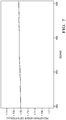
- FIG. 7 shows a pedestrian height estimated by an Extended Kalman Filter over time.
- One or more includes a function being performed by one element, a function being performed by more than one element, e.g., in a distributed fashion, several functions being performed by one element, several functions being performed by several elements, or any combination of the above.
- first, second, etc. are, in some instances, used herein to describe various elements, these elements should not be limited by these terms. These terms are only used to distinguish one element from another.
- a first contact could be termed a second contact, and, similarly, a second contact could be termed a first contact, without departing from the scope of the various described embodiments.
- the first contact and the second contact are both contacts, but they are not the same contact.
- the term “if” is, optionally, construed to mean “when” or “upon” or “in response to determining” or “in response to detecting,” depending on the context.
- the phrase “if it is determined” or “if [a stated condition or event] is detected” is, optionally, construed to mean “upon determining” or “in response to determining” or “upon detecting [the stated condition or event]” or “in response to detecting [the stated condition or event],” depending on the context.
- FIG. 1 there is shown a motor vehicle 11 and a radar sensor system 13 mounted to a front section of the motor vehicle 11 .
- the radar sensor system 13 is preferably based on a millimeter wave radar sensor.
- a single channel radar sensor is preferred to minimize the production costs.
- a multiple channel radar sensor may be provided to enhance the detection performance.
- the radar sensor system 13 can be connected to an electronic processing device (not shown), for example an advanced emergency braking system, a pedestrian collision avoidance system or an autonomous driving system.
- the motor vehicle 11 is moving in a driving direction 15 on a lane 17 .
- a pedestrian 19 crossing the lane 17 is moving in a moving direction 21 .
- the moving direction 21 is at least essentially perpendicular to the driving direction 15 .
- the moving direction 21 may be inclined to the driving direction 15 .
- the radar sensor system 13 is configured for transmitting a primary radar signal into the traffic space 23 in front of the motor vehicle 11 and for detecting pedestrians 19 present in the traffic space 23 on the basis of a secondary radar signal reflected by the pedestrians 19 .
- the line 25 which extends from the pedestrian 19 to the active region of the radar sensor system 13 is called “line of sight”.
- the observed bulk speed v ob of the pedestrian 19 i. e. the speed component related to the pedestrian's torso 27 and oriented along the line of sight 25 , can be determined in a known manner using the Doppler effect.
- the illumination angle ⁇ and the speed v are determined on the basis of a Micro-Doppler spectrogram analysis by means of the electronic processing device, as is explained in greater detail below.
- a Micro-Doppler spectrogram 30 is generated as an input for the subsequent steps.
- the observed bulk speed v ob of the moving pedestrian 19 is determined based on the Micro-Doppler spectrogram 30 .
- a gait cycle parameter in form of a gait cycle duration T gaitcycle of the moving pedestrian 19 is determined based on the Micro-Doppler spectrogram 30 .
- the illumination angle ⁇ is determined based on the observed bulk speed v ob as determined in step 31 and the gait cycle parameter T gaitcycle as determined in step 32 .
- the speed v of the moving pedestrian 19 in the moving direction 21 ( FIG. 1 ) is determined based on the observed bulk speed v ob as determined in step 31 and the illumination angle ⁇ as determined in step 33 .
- the generation of the Micro-Doppler spectrogram 30 is carried out by means of a Short-Time-Fourier-Transform (STFT) or a Wigner-Ville-Distribution technique (WVD technique).
- STFT Short-Time-Fourier-Transform
- WVD technique Wigner-Ville-Distribution technique
- FIG. 3 An exemplary Micro-Doppler spectrogram 30 is shown in FIG. 3 .
- the horizontal axis is a time axis, whereas the vertical axis is a Doppler shift axis.
- a segment of the Micro-Doppler spectrogram 30 that corresponds to a gait cycle of the pedestrian 19 .
- a gait cycle lasts from a ground contact of a certain foot to the next ground contact of this foot and thus usually corresponds to two consecutive footsteps.
- the periodic movement of the feet during walking generates an at least essentially periodic pattern in the Micro-Doppler spectrogram 30 .
- FIG. 4 shows the right portion of the Micro-Doppler spectrogram 30 according to FIG. 3 in an enlarged view.
- Three curves corresponding to the courses of different motion components are shown in the Micro-Doppler spectrogram 30 .
- the course 40 of the observed bulk speed v ob is shown as a solid black line
- the upper envelope 41 of the Micro-Doppler spectrogram 30 and the lower envelope 42 of the Micro-Doppler spectrogram 30 are shown as dashed lines.
- the cumulative amplitude distribution function is determined for each time slice.
- the course 40 of the observed bulk speed v ob is assigned to a percentile of about 50% of the cumulative amplitude distribution function.
- the upper envelope 41 is assigned to a percentile of about 95% of the cumulative amplitude distribution function, whereas the lower envelope 42 is assigned to a percentile of about 5% of the cumulative amplitude distribution function.
- the repetition frequency of the gait cycle is estimated.
- the duration of the gait cycle T gaitcycle is the reciprocal of the repetition frequency of the gait cycle.
- the duration of the gait cycle T gaitcycle can be expressed as:
- T gaitcycle 1.346 v / H t ( 2 ) wherein H t is the height of the pedestrian's thigh.
- H t is the height of the pedestrian's thigh.
- H t is the height of the pedestrian's thigh.
- H t is the height of the pedestrian's thigh.
- H t is the height of the pedestrian's thigh.
- the factor 2 accounts for the above mentioned fact that usually one gait-cycle comprises two footsteps.
- vN footstep 2 KH ped (5)
- v ob N footstep 2 KH ped cos( ⁇ ) (6)
- K is a constant for a given spectrogram:
- the illumination angle ⁇ can be determined from equation (8).
- One variant for calculating the illumination angle ⁇ is to use equation (8) and to set H ped as the statistical average pedestrian height H ped_avg for the dedicated application scenario.
- the angle estimation error induced by the unknown pedestrian height is:
- the angle estimation error is be below 6° for an illumination angle ⁇ varying between 60° and 120°, which is sufficient for most applications.
- the illumination angle ⁇ is always between 60° and 120°.
- Another variant of estimating the illumination angle ⁇ is to use a recursive state estimator such as an Extended Kalman Filter (EKF).
- EKF Extended Kalman Filter
- [ ⁇ n ⁇ n * N footstep , n H ped , n ] [ 1 ⁇ Timebin 0 0 0 1 0 0 0 0 1 0 0 0 1 ] ⁇ [ ⁇ n - 1 ⁇ n - 1 * N footstep , ⁇ n - 1 H ped , ⁇ n - 1 ] + W 1 ( 10 )
- [ v n ob N footstep , n ] [ KH ped , ⁇ n ⁇ cos ⁇ ( ⁇ n ) / N footstep , ⁇ n 2 N footstep , ⁇ n ] + q ( 11 ) wherein the random variables w n ⁇ 1 and q n represent the process noise and the measurement noise.
- the subscripts n, n ⁇ 1 indicate the current state and the previous state, respectively.
- the dot refers to the derivative of ⁇ .
- FIG. 6 shows the estimated illumination angle ⁇ for a series of scans of the radar sensor system 13 ( FIG. 1 ).
- the EKF based method provides a more reliable estimation than methods based on exemplary fixed heights.
- H ped is a component of the state vector of the EKF as given in equation (10), it can also be estimated by the EKF.
- An example of such an estimation is shown in FIG. 7 .
- the invention enables a reliable recognition of moving pedestrians by means of a radar sensor system without the necessity to use complex and expensive hardware. While this invention has been described in terms of the preferred embodiments thereof, it is not intended to be so limited, but rather only to the extent set forth in the claims that follow.
Landscapes
- Engineering & Computer Science (AREA)
- Remote Sensing (AREA)
- Radar, Positioning & Navigation (AREA)
- Physics & Mathematics (AREA)
- General Physics & Mathematics (AREA)
- Computer Networks & Wireless Communication (AREA)
- Human Computer Interaction (AREA)
- Multimedia (AREA)
- Theoretical Computer Science (AREA)
- Electromagnetism (AREA)
- Social Psychology (AREA)
- Psychiatry (AREA)
- Health & Medical Sciences (AREA)
- General Health & Medical Sciences (AREA)
- Computer Vision & Pattern Recognition (AREA)
- Radar Systems Or Details Thereof (AREA)
Applications Claiming Priority (3)
| Application Number | Priority Date | Filing Date | Title |
|---|---|---|---|
| EP18166844 | 2018-04-11 | ||
| EP18166844.3A EP3553552B1 (de) | 2018-04-11 | 2018-04-11 | Verfahren zur erkennung eines sich bewegenden fussgängers |
| EP18166844.3 | 2018-04-11 |
Publications (2)
| Publication Number | Publication Date |
|---|---|
| US20190318162A1 US20190318162A1 (en) | 2019-10-17 |
| US10929653B2 true US10929653B2 (en) | 2021-02-23 |
Family
ID=61971970
Family Applications (1)
| Application Number | Title | Priority Date | Filing Date |
|---|---|---|---|
| US16/361,897 Active 2039-05-28 US10929653B2 (en) | 2018-04-11 | 2019-03-22 | Method for the recognition of a moving pedestrian |
Country Status (3)
| Country | Link |
|---|---|
| US (1) | US10929653B2 (de) |
| EP (1) | EP3553552B1 (de) |
| CN (1) | CN110361737B (de) |
Cited By (8)
| Publication number | Priority date | Publication date | Assignee | Title |
|---|---|---|---|---|
| US20210142662A1 (en) * | 2018-04-12 | 2021-05-13 | Robert Bosch Gmbh | Method for detecting an obstacle in front of a vehicle |
| US20210141052A1 (en) * | 2019-11-08 | 2021-05-13 | Richwave Technology Corp. | Radar and Method of Updating Background Components of Echo Signal of Radar |
| US11131766B2 (en) | 2018-04-10 | 2021-09-28 | Aptiv Technologies Limited | Method for the recognition of an object |
| US11402486B2 (en) | 2018-04-11 | 2022-08-02 | Aptiv Technologies Limited | Method for the recognition of objects |
| US20230055654A1 (en) * | 2019-12-31 | 2023-02-23 | Essence Smartcare Ltd. | State Detection |
| US20240027597A1 (en) * | 2020-11-27 | 2024-01-25 | Kyocera Corporation | Electronic device, method for controlling electronic device, and program |
| US12523761B2 (en) | 2019-12-31 | 2026-01-13 | Essence Smartcare Ltd. | Device for monitoring an environment |
| US12618964B2 (en) * | 2019-12-31 | 2026-05-05 | Essence Smartcare Ltd. | State detection |
Families Citing this family (8)
| Publication number | Priority date | Publication date | Assignee | Title |
|---|---|---|---|---|
| EP4075162A4 (de) * | 2019-12-09 | 2023-12-27 | Kyocera Corporation | Elektronische vorrichtung, verfahren zum steuern einer elektronischen vorrichtung und programm |
| KR102227393B1 (ko) * | 2020-02-03 | 2021-03-15 | 재단법인대구경북과학기술원 | 도플러 정보 기반의 보행자 및 차량 인식 장치 및 그 방법 |
| US11415670B2 (en) | 2020-03-20 | 2022-08-16 | Aptiv Technologies Limited | Object classification using low-level radar data |
| JP2022138848A (ja) * | 2021-03-11 | 2022-09-26 | マツダ株式会社 | レーダによる移動体検出方法 |
| CN113189555B (zh) * | 2021-04-12 | 2023-02-14 | 浙江大学 | 基于时-距包围盒目标截取的多目标分割方法、步态识别方法、装置、系统和存储介质 |
| US12463675B2 (en) * | 2021-08-05 | 2025-11-04 | Samsung Electronics Co., Ltd. | Radio frequency exposure estimation with radar for mobile devices |
| CN114089328A (zh) * | 2021-11-23 | 2022-02-25 | 扬州宇安电子科技有限公司 | 确定行人移动速度的方法及行人定位方法、车载雷达 |
| CN116453227B (zh) * | 2023-06-19 | 2023-09-19 | 武汉理工大学 | 一种基于双毫米波雷达的船舶环境下步态识别方法 |
Citations (31)
| Publication number | Priority date | Publication date | Assignee | Title |
|---|---|---|---|---|
| US4958638A (en) | 1988-06-30 | 1990-09-25 | Georgia Tech Research Corporation | Non-contact vital signs monitor |
| US5689268A (en) | 1996-08-02 | 1997-11-18 | Boeing North American, Inc. | Radar detection and classification of helicopters |
| US6121916A (en) | 1999-07-16 | 2000-09-19 | Eaton-Vorad Technologies, L.L.C. | Method and apparatus for recognizing stationary objects with a moving side-looking radar |
| US20020028003A1 (en) * | 2000-03-27 | 2002-03-07 | Krebs David E. | Methods and systems for distinguishing individuals utilizing anatomy and gait parameters |
| US6653971B1 (en) | 1999-05-14 | 2003-11-25 | David L. Guice | Airborne biota monitoring and control system |
| US20030225517A1 (en) | 2002-05-30 | 2003-12-04 | Schiffmann Jan K. | Collision detection system and method of estimating miss distance |
| US6674394B1 (en) | 2003-03-28 | 2004-01-06 | Visteon Global Technologies, Inc. | Method for determining object location from side-looking sensor data |
| US20100074379A1 (en) | 2008-04-01 | 2010-03-25 | Ming-Chiang Li | Tuning replica generation methods and apparatus for their most optimum performance in processing transient signals |
| US20110102234A1 (en) | 2009-11-03 | 2011-05-05 | Vawd Applied Science And Technology Corporation | Standoff range sense through obstruction radar system |
| US20130329523A1 (en) | 2010-12-01 | 2013-12-12 | Matthias Karl | Driver assistance system for detecting an object in the surroundings of a vehicle |
| US20140261887A1 (en) | 2011-11-03 | 2014-09-18 | Thales Nederland B.V. | System for characterizing motion of an individual, notably a human individual, and associated method |
| US8854251B2 (en) | 2010-06-16 | 2014-10-07 | Toyota Jidosha Kabushiki Kaisha | Object identification device and method |
| CN104360336A (zh) | 2014-11-24 | 2015-02-18 | 电子科技大学 | 一种自适应提取雷达目标微动周期的新方法 |
| US20160054438A1 (en) | 2014-08-25 | 2016-02-25 | Texas Instruments Incorporated | Vibration parameters monitoring using fmcw radar |
| DE102014218092A1 (de) | 2014-09-10 | 2016-03-10 | Volkswagen Aktiengesellschaft | Erstellen eines Abbilds der Umgebung eines Kraftfahrzeugs und Bestimmen der relativen Geschwindigkeit zwischen dem Kraftfahrzeug und Objekten in der Umgebung |
| US20160124087A1 (en) | 2014-09-05 | 2016-05-05 | GM Global Technology Operations LLC | Object boundary detection for automotive radar imaging |
| US20160259037A1 (en) | 2015-03-03 | 2016-09-08 | Nvidia Corporation | Radar based user interface |
| US20160320853A1 (en) | 2015-04-30 | 2016-11-03 | Google Inc. | RF-Based Micro-Motion Tracking for Gesture Tracking and Recognition |
| DE102015007040A1 (de) | 2015-05-30 | 2016-12-01 | Audi Ag | Verfahren zur Detektion und Klassifikation von Fußgängern in einer Umgebung eines Kraftfahrzeugs und Kraftfahrzeug |
| US20170057497A1 (en) | 2015-08-28 | 2017-03-02 | Delphi Technologies, Inc. | Pedestrian-intent-detection for automated vehicles |
| WO2017039862A1 (en) | 2015-08-31 | 2017-03-09 | Autoliv Asp, Inc. | Apparatus and method for detecting blockage of an automotive radar sensor |
| US20170085771A1 (en) | 2014-03-27 | 2017-03-23 | Sony Corporation | Camera with radar system |
| US20170097413A1 (en) | 2015-10-06 | 2017-04-06 | Google Inc. | Radar-Enabled Sensor Fusion |
| DE102016213254B3 (de) | 2016-07-20 | 2017-07-13 | Volkswagen Aktiengesellschaft | Verfahren zum Erfassen einer Objektbewegung eines Objekts in einer Umgebung eines Kraftfahrzeugs, Steuervorrichtung und Kraftfahrzeugs |
| US20170276788A1 (en) | 2016-03-25 | 2017-09-28 | Magna Electronics Inc. | Vehicle short range sensing system using rf sensors |
| DE102016215102A1 (de) | 2016-08-12 | 2017-12-07 | Conti Temic Microelectronic Gmbh | Fußgängererkennung mittels Radar |
| US20170356991A1 (en) | 2016-06-13 | 2017-12-14 | Panasonic Intellectual Property Management Co., Ltd. | Radar device and detection method |
| DE102016213007A1 (de) | 2016-07-15 | 2018-01-18 | Robert Bosch Gmbh | Verfahren und System zur Abtastung eines Objekts |
| US20200064444A1 (en) * | 2015-07-17 | 2020-02-27 | Origin Wireless, Inc. | Method, apparatus, and system for human identification based on human radio biometric information |
| US20200124706A1 (en) | 2017-07-05 | 2020-04-23 | Robert Bosch Gmbh | System for detecting a moving object |
| US20200160046A1 (en) * | 2017-06-30 | 2020-05-21 | The Johns Hopkins University | Systems and method for action recognition using micro-doppler signatures and recurrent neural networks |
Family Cites Families (7)
| Publication number | Priority date | Publication date | Assignee | Title |
|---|---|---|---|---|
| JP2012189338A (ja) * | 2011-03-08 | 2012-10-04 | Panasonic Corp | レーダ装置及び移動機器用レーダシステム |
| DE102012107445B8 (de) * | 2012-08-14 | 2016-04-28 | Jenoptik Robot Gmbh | Verfahren zur Klassifizierung von fahrenden Fahrzeugen |
| US9594159B2 (en) * | 2013-07-15 | 2017-03-14 | Texas Instruments Incorporated | 2-D object detection in radar applications |
| CN104330791B (zh) * | 2014-10-24 | 2017-03-29 | 上海无线电设备研究所 | 一种基于频域切变的相参积累方法 |
| JP6778873B2 (ja) * | 2016-08-10 | 2020-11-04 | パナソニックIpマネジメント株式会社 | レーダ設置角度算出装置、レーダ装置およびレーダ設置角度算出方法 |
| CN107358250B (zh) * | 2017-06-07 | 2019-11-22 | 清华大学 | 基于双波段雷达微多普勒融合的人体步态识别方法及系统 |
| EP3553551B1 (de) * | 2018-04-10 | 2022-06-01 | Aptiv Technologies Limited | Verfahren zur erkennung eines objekts |
-
2018
- 2018-04-11 EP EP18166844.3A patent/EP3553552B1/de active Active
-
2019
- 2019-03-22 US US16/361,897 patent/US10929653B2/en active Active
- 2019-04-09 CN CN201910279440.8A patent/CN110361737B/zh active Active
Patent Citations (32)
| Publication number | Priority date | Publication date | Assignee | Title |
|---|---|---|---|---|
| US4958638A (en) | 1988-06-30 | 1990-09-25 | Georgia Tech Research Corporation | Non-contact vital signs monitor |
| US5689268A (en) | 1996-08-02 | 1997-11-18 | Boeing North American, Inc. | Radar detection and classification of helicopters |
| US6653971B1 (en) | 1999-05-14 | 2003-11-25 | David L. Guice | Airborne biota monitoring and control system |
| US6121916A (en) | 1999-07-16 | 2000-09-19 | Eaton-Vorad Technologies, L.L.C. | Method and apparatus for recognizing stationary objects with a moving side-looking radar |
| US20020028003A1 (en) * | 2000-03-27 | 2002-03-07 | Krebs David E. | Methods and systems for distinguishing individuals utilizing anatomy and gait parameters |
| US20030225517A1 (en) | 2002-05-30 | 2003-12-04 | Schiffmann Jan K. | Collision detection system and method of estimating miss distance |
| US6674394B1 (en) | 2003-03-28 | 2004-01-06 | Visteon Global Technologies, Inc. | Method for determining object location from side-looking sensor data |
| US20100074379A1 (en) | 2008-04-01 | 2010-03-25 | Ming-Chiang Li | Tuning replica generation methods and apparatus for their most optimum performance in processing transient signals |
| US20110102234A1 (en) | 2009-11-03 | 2011-05-05 | Vawd Applied Science And Technology Corporation | Standoff range sense through obstruction radar system |
| US8854251B2 (en) | 2010-06-16 | 2014-10-07 | Toyota Jidosha Kabushiki Kaisha | Object identification device and method |
| US20130329523A1 (en) | 2010-12-01 | 2013-12-12 | Matthias Karl | Driver assistance system for detecting an object in the surroundings of a vehicle |
| US20140261887A1 (en) | 2011-11-03 | 2014-09-18 | Thales Nederland B.V. | System for characterizing motion of an individual, notably a human individual, and associated method |
| US20170085771A1 (en) | 2014-03-27 | 2017-03-23 | Sony Corporation | Camera with radar system |
| US20160054438A1 (en) | 2014-08-25 | 2016-02-25 | Texas Instruments Incorporated | Vibration parameters monitoring using fmcw radar |
| US20160124087A1 (en) | 2014-09-05 | 2016-05-05 | GM Global Technology Operations LLC | Object boundary detection for automotive radar imaging |
| DE102014218092A1 (de) | 2014-09-10 | 2016-03-10 | Volkswagen Aktiengesellschaft | Erstellen eines Abbilds der Umgebung eines Kraftfahrzeugs und Bestimmen der relativen Geschwindigkeit zwischen dem Kraftfahrzeug und Objekten in der Umgebung |
| CN104360336A (zh) | 2014-11-24 | 2015-02-18 | 电子科技大学 | 一种自适应提取雷达目标微动周期的新方法 |
| US20160259037A1 (en) | 2015-03-03 | 2016-09-08 | Nvidia Corporation | Radar based user interface |
| US20160320853A1 (en) | 2015-04-30 | 2016-11-03 | Google Inc. | RF-Based Micro-Motion Tracking for Gesture Tracking and Recognition |
| DE102015007040A1 (de) | 2015-05-30 | 2016-12-01 | Audi Ag | Verfahren zur Detektion und Klassifikation von Fußgängern in einer Umgebung eines Kraftfahrzeugs und Kraftfahrzeug |
| US20200064444A1 (en) * | 2015-07-17 | 2020-02-27 | Origin Wireless, Inc. | Method, apparatus, and system for human identification based on human radio biometric information |
| US20170057497A1 (en) | 2015-08-28 | 2017-03-02 | Delphi Technologies, Inc. | Pedestrian-intent-detection for automated vehicles |
| WO2017039862A1 (en) | 2015-08-31 | 2017-03-09 | Autoliv Asp, Inc. | Apparatus and method for detecting blockage of an automotive radar sensor |
| US20170097413A1 (en) | 2015-10-06 | 2017-04-06 | Google Inc. | Radar-Enabled Sensor Fusion |
| US20170276788A1 (en) | 2016-03-25 | 2017-09-28 | Magna Electronics Inc. | Vehicle short range sensing system using rf sensors |
| US20170356991A1 (en) | 2016-06-13 | 2017-12-14 | Panasonic Intellectual Property Management Co., Ltd. | Radar device and detection method |
| DE102016213007A1 (de) | 2016-07-15 | 2018-01-18 | Robert Bosch Gmbh | Verfahren und System zur Abtastung eines Objekts |
| US20190137606A1 (en) | 2016-07-15 | 2019-05-09 | Robert Bosch Gmbh | Method and system for scanning an object |
| DE102016213254B3 (de) | 2016-07-20 | 2017-07-13 | Volkswagen Aktiengesellschaft | Verfahren zum Erfassen einer Objektbewegung eines Objekts in einer Umgebung eines Kraftfahrzeugs, Steuervorrichtung und Kraftfahrzeugs |
| DE102016215102A1 (de) | 2016-08-12 | 2017-12-07 | Conti Temic Microelectronic Gmbh | Fußgängererkennung mittels Radar |
| US20200160046A1 (en) * | 2017-06-30 | 2020-05-21 | The Johns Hopkins University | Systems and method for action recognition using micro-doppler signatures and recurrent neural networks |
| US20200124706A1 (en) | 2017-07-05 | 2020-04-23 | Robert Bosch Gmbh | System for detecting a moving object |
Non-Patent Citations (12)
Cited By (10)
| Publication number | Priority date | Publication date | Assignee | Title |
|---|---|---|---|---|
| US11131766B2 (en) | 2018-04-10 | 2021-09-28 | Aptiv Technologies Limited | Method for the recognition of an object |
| US11402486B2 (en) | 2018-04-11 | 2022-08-02 | Aptiv Technologies Limited | Method for the recognition of objects |
| US20210142662A1 (en) * | 2018-04-12 | 2021-05-13 | Robert Bosch Gmbh | Method for detecting an obstacle in front of a vehicle |
| US12033504B2 (en) * | 2018-04-12 | 2024-07-09 | Robert Bosch Gmbh | Method for detecting an obstacle in front of a vehicle |
| US20210141052A1 (en) * | 2019-11-08 | 2021-05-13 | Richwave Technology Corp. | Radar and Method of Updating Background Components of Echo Signal of Radar |
| US11573287B2 (en) * | 2019-11-08 | 2023-02-07 | Richwave Technology Corp. | Radar and method of updating background components of echo signal of radar |
| US20230055654A1 (en) * | 2019-12-31 | 2023-02-23 | Essence Smartcare Ltd. | State Detection |
| US12523761B2 (en) | 2019-12-31 | 2026-01-13 | Essence Smartcare Ltd. | Device for monitoring an environment |
| US12618964B2 (en) * | 2019-12-31 | 2026-05-05 | Essence Smartcare Ltd. | State detection |
| US20240027597A1 (en) * | 2020-11-27 | 2024-01-25 | Kyocera Corporation | Electronic device, method for controlling electronic device, and program |
Also Published As
| Publication number | Publication date |
|---|---|
| US20190318162A1 (en) | 2019-10-17 |
| EP3553552B1 (de) | 2022-05-25 |
| CN110361737B (zh) | 2023-05-23 |
| EP3553552A1 (de) | 2019-10-16 |
| CN110361737A (zh) | 2019-10-22 |
Similar Documents
| Publication | Publication Date | Title |
|---|---|---|
| US10929653B2 (en) | Method for the recognition of a moving pedestrian | |
| US11131766B2 (en) | Method for the recognition of an object | |
| CN110832340B (zh) | 用于探测运动对象的系统 | |
| US9971022B2 (en) | Radar apparatus | |
| US11099258B2 (en) | Method and system for scanning an object | |
| US6266005B1 (en) | Method for processing radar signals | |
| US9812008B2 (en) | Vehicle detection and tracking based on wheels using radar and vision | |
| JP7173735B2 (ja) | レーダ装置及び信号処理方法 | |
| KR20190125453A (ko) | 하나 이상의 표적의 반경방향 상대 가속도를 결정하기 위한 방법 및 레이더 장치 | |
| JP6993136B2 (ja) | レーダ装置および物標検知方法 | |
| Schubert et al. | A multi-reflection-point target model for classification of pedestrians by automotive radar | |
| CN111615641A (zh) | 用于探测关键横向运动的方法和设备 | |
| Held et al. | Micro-doppler extraction of bicycle pedaling movements using automotive radar | |
| CN110678776B (zh) | 用于增强的对象跟踪的系统 | |
| EP3290945A1 (de) | Fehlausrichtungserkennung für einen fahrzeugradarsensor | |
| JP7167871B2 (ja) | 物標検出装置 | |
| CN110691985B (zh) | 用于增强的对象追踪的系统 | |
| Steiner et al. | Cooperative target detection in a network of single-channel radar sensors | |
| CN114089328A (zh) | 确定行人移动速度的方法及行人定位方法、车载雷达 | |
| Schubert et al. | Target modeling and deduction of automotive radar resolution requirements for pedestrian classification | |
| JP2008026239A (ja) | レーダ |
Legal Events
| Date | Code | Title | Description |
|---|---|---|---|
| FEPP | Fee payment procedure |
Free format text: ENTITY STATUS SET TO UNDISCOUNTED (ORIGINAL EVENT CODE: BIG.); ENTITY STATUS OF PATENT OWNER: LARGE ENTITY |
|
| AS | Assignment |
Owner name: APTIV TECHNOLOGIES LIMITED, BARBADOS Free format text: ASSIGNMENT OF ASSIGNORS INTEREST;ASSIGNORS:YAN, HONGHUI;ZHANG, TAO;DOERR, WOLFGANG;AND OTHERS;SIGNING DATES FROM 20190402 TO 20190404;REEL/FRAME:048796/0449 |
|
| STCF | Information on status: patent grant |
Free format text: PATENTED CASE |
|
| AS | Assignment |
Owner name: APTIV TECHNOLOGIES (2) S.A R.L., LUXEMBOURG Free format text: ENTITY CONVERSION;ASSIGNOR:APTIV TECHNOLOGIES LIMITED;REEL/FRAME:066746/0001 Effective date: 20230818 Owner name: APTIV MANUFACTURING MANAGEMENT SERVICES S.A R.L., LUXEMBOURG Free format text: MERGER;ASSIGNOR:APTIV TECHNOLOGIES (2) S.A R.L.;REEL/FRAME:066566/0173 Effective date: 20231005 Owner name: APTIV TECHNOLOGIES AG, SWITZERLAND Free format text: ASSIGNMENT OF ASSIGNORS INTEREST;ASSIGNOR:APTIV MANUFACTURING MANAGEMENT SERVICES S.A R.L.;REEL/FRAME:066551/0219 Effective date: 20231006 |
|
| MAFP | Maintenance fee payment |
Free format text: PAYMENT OF MAINTENANCE FEE, 4TH YEAR, LARGE ENTITY (ORIGINAL EVENT CODE: M1551); ENTITY STATUS OF PATENT OWNER: LARGE ENTITY Year of fee payment: 4 |