US10938149B2 - Convertible force latching system - Google Patents
Convertible force latching system Download PDFInfo
- Publication number
- US10938149B2 US10938149B2 US16/229,121 US201816229121A US10938149B2 US 10938149 B2 US10938149 B2 US 10938149B2 US 201816229121 A US201816229121 A US 201816229121A US 10938149 B2 US10938149 B2 US 10938149B2
- Authority
- US
- United States
- Prior art keywords
- series
- magnets
- connector body
- magnet
- latching system
- Prior art date
- Legal status (The legal status is an assumption and is not a legal conclusion. Google has not performed a legal analysis and makes no representation as to the accuracy of the status listed.)
- Active
Links
Images


Classifications
-
- H—ELECTRICITY
- H01—ELECTRIC ELEMENTS
- H01R—ELECTRICALLY-CONDUCTIVE CONNECTIONS; STRUCTURAL ASSOCIATIONS OF A PLURALITY OF MUTUALLY-INSULATED ELECTRICAL CONNECTING ELEMENTS; COUPLING DEVICES; CURRENT COLLECTORS
- H01R13/00—Details of coupling devices of the kinds covered by groups H01R12/70 or H01R24/00 - H01R33/00
- H01R13/62—Means for facilitating engagement or disengagement of coupling parts or for holding them in engagement
- H01R13/6205—Two-part coupling devices held in engagement by a magnet
-
- G—PHYSICS
- G06—COMPUTING OR CALCULATING; COUNTING
- G06F—ELECTRIC DIGITAL DATA PROCESSING
- G06F12/00—Accessing, addressing or allocating within memory systems or architectures
- G06F12/02—Addressing or allocation; Relocation
- G06F12/08—Addressing or allocation; Relocation in hierarchically structured memory systems, e.g. virtual memory systems
- G06F12/0802—Addressing of a memory level in which the access to the desired data or data block requires associative addressing means, e.g. caches
- G06F12/0804—Addressing of a memory level in which the access to the desired data or data block requires associative addressing means, e.g. caches with main memory updating
-
- G—PHYSICS
- G06—COMPUTING OR CALCULATING; COUNTING
- G06F—ELECTRIC DIGITAL DATA PROCESSING
- G06F12/00—Accessing, addressing or allocating within memory systems or architectures
- G06F12/02—Addressing or allocation; Relocation
- G06F12/08—Addressing or allocation; Relocation in hierarchically structured memory systems, e.g. virtual memory systems
- G06F12/0802—Addressing of a memory level in which the access to the desired data or data block requires associative addressing means, e.g. caches
- G06F12/0864—Addressing of a memory level in which the access to the desired data or data block requires associative addressing means, e.g. caches using pseudo-associative means, e.g. set-associative or hashing
-
- G—PHYSICS
- G06—COMPUTING OR CALCULATING; COUNTING
- G06F—ELECTRIC DIGITAL DATA PROCESSING
- G06F12/00—Accessing, addressing or allocating within memory systems or architectures
- G06F12/02—Addressing or allocation; Relocation
- G06F12/08—Addressing or allocation; Relocation in hierarchically structured memory systems, e.g. virtual memory systems
- G06F12/0802—Addressing of a memory level in which the access to the desired data or data block requires associative addressing means, e.g. caches
- G06F12/0891—Addressing of a memory level in which the access to the desired data or data block requires associative addressing means, e.g. caches using clearing, invalidating or resetting means
-
- G—PHYSICS
- G06—COMPUTING OR CALCULATING; COUNTING
- G06F—ELECTRIC DIGITAL DATA PROCESSING
- G06F21/00—Security arrangements for protecting computers, components thereof, programs or data against unauthorised activity
- G06F21/60—Protecting data
- G06F21/602—Providing cryptographic facilities or services
-
- G—PHYSICS
- G06—COMPUTING OR CALCULATING; COUNTING
- G06F—ELECTRIC DIGITAL DATA PROCESSING
- G06F9/00—Arrangements for program control, e.g. control units
- G06F9/06—Arrangements for program control, e.g. control units using stored programs, i.e. using an internal store of processing equipment to receive or retain programs
- G06F9/44—Arrangements for executing specific programs
- G06F9/455—Emulation; Interpretation; Software simulation, e.g. virtualisation or emulation of application or operating system execution engines
- G06F9/45533—Hypervisors; Virtual machine monitors
- G06F9/45558—Hypervisor-specific management and integration aspects
-
- H—ELECTRICITY
- H01—ELECTRIC ELEMENTS
- H01R—ELECTRICALLY-CONDUCTIVE CONNECTIONS; STRUCTURAL ASSOCIATIONS OF A PLURALITY OF MUTUALLY-INSULATED ELECTRICAL CONNECTING ELEMENTS; COUPLING DEVICES; CURRENT COLLECTORS
- H01R13/00—Details of coupling devices of the kinds covered by groups H01R12/70 or H01R24/00 - H01R33/00
- H01R13/62—Means for facilitating engagement or disengagement of coupling parts or for holding them in engagement
- H01R13/629—Additional means for facilitating engagement or disengagement of coupling parts, e.g. aligning or guiding means, levers, gas pressure electrical locking indicators, manufacturing tolerances
- H01R13/631—Additional means for facilitating engagement or disengagement of coupling parts, e.g. aligning or guiding means, levers, gas pressure electrical locking indicators, manufacturing tolerances for engagement only
-
- H—ELECTRICITY
- H01—ELECTRIC ELEMENTS
- H01R—ELECTRICALLY-CONDUCTIVE CONNECTIONS; STRUCTURAL ASSOCIATIONS OF A PLURALITY OF MUTUALLY-INSULATED ELECTRICAL CONNECTING ELEMENTS; COUPLING DEVICES; CURRENT COLLECTORS
- H01R13/00—Details of coupling devices of the kinds covered by groups H01R12/70 or H01R24/00 - H01R33/00
- H01R13/62—Means for facilitating engagement or disengagement of coupling parts or for holding them in engagement
- H01R13/629—Additional means for facilitating engagement or disengagement of coupling parts, e.g. aligning or guiding means, levers, gas pressure electrical locking indicators, manufacturing tolerances
- H01R13/633—Additional means for facilitating engagement or disengagement of coupling parts, e.g. aligning or guiding means, levers, gas pressure electrical locking indicators, manufacturing tolerances for disengagement only
-
- H—ELECTRICITY
- H01—ELECTRIC ELEMENTS
- H01R—ELECTRICALLY-CONDUCTIVE CONNECTIONS; STRUCTURAL ASSOCIATIONS OF A PLURALITY OF MUTUALLY-INSULATED ELECTRICAL CONNECTING ELEMENTS; COUPLING DEVICES; CURRENT COLLECTORS
- H01R13/00—Details of coupling devices of the kinds covered by groups H01R12/70 or H01R24/00 - H01R33/00
- H01R13/62—Means for facilitating engagement or disengagement of coupling parts or for holding them in engagement
- H01R13/639—Additional means for holding or locking coupling parts together, after engagement, e.g. separate keylock, retainer strap
-
- H—ELECTRICITY
- H04—ELECTRIC COMMUNICATION TECHNIQUE
- H04L—TRANSMISSION OF DIGITAL INFORMATION, e.g. TELEGRAPHIC COMMUNICATION
- H04L9/00—Cryptographic mechanisms or cryptographic arrangements for secret or secure communications; Network security protocols
- H04L9/08—Key distribution or management, e.g. generation, sharing or updating, of cryptographic keys or passwords
- H04L9/0861—Generation of secret information including derivation or calculation of cryptographic keys or passwords
- H04L9/0866—Generation of secret information including derivation or calculation of cryptographic keys or passwords involving user or device identifiers, e.g. serial number, physical or biometrical information, DNA, hand-signature or measurable physical characteristics
-
- G—PHYSICS
- G06—COMPUTING OR CALCULATING; COUNTING
- G06F—ELECTRIC DIGITAL DATA PROCESSING
- G06F9/00—Arrangements for program control, e.g. control units
- G06F9/06—Arrangements for program control, e.g. control units using stored programs, i.e. using an internal store of processing equipment to receive or retain programs
- G06F9/44—Arrangements for executing specific programs
- G06F9/455—Emulation; Interpretation; Software simulation, e.g. virtualisation or emulation of application or operating system execution engines
- G06F9/45533—Hypervisors; Virtual machine monitors
- G06F9/45558—Hypervisor-specific management and integration aspects
- G06F2009/45583—Memory management, e.g. access or allocation
-
- H—ELECTRICITY
- H01—ELECTRIC ELEMENTS
- H01R—ELECTRICALLY-CONDUCTIVE CONNECTIONS; STRUCTURAL ASSOCIATIONS OF A PLURALITY OF MUTUALLY-INSULATED ELECTRICAL CONNECTING ELEMENTS; COUPLING DEVICES; CURRENT COLLECTORS
- H01R13/00—Details of coupling devices of the kinds covered by groups H01R12/70 or H01R24/00 - H01R33/00
- H01R13/02—Contact members
- H01R13/10—Sockets for co-operation with pins or blades
- H01R13/11—Resilient sockets
- H01R13/111—Resilient sockets co-operating with pins having a circular transverse section
-
- H—ELECTRICITY
- H01—ELECTRIC ELEMENTS
- H01R—ELECTRICALLY-CONDUCTIVE CONNECTIONS; STRUCTURAL ASSOCIATIONS OF A PLURALITY OF MUTUALLY-INSULATED ELECTRICAL CONNECTING ELEMENTS; COUPLING DEVICES; CURRENT COLLECTORS
- H01R13/00—Details of coupling devices of the kinds covered by groups H01R12/70 or H01R24/00 - H01R33/00
- H01R13/64—Means for preventing incorrect coupling
- H01R13/645—Means for preventing incorrect coupling by exchangeable elements on case or base
- H01R13/6456—Means for preventing incorrect coupling by exchangeable elements on case or base comprising keying elements at different positions along the periphery of the connector
-
- H—ELECTRICITY
- H01—ELECTRIC ELEMENTS
- H01R—ELECTRICALLY-CONDUCTIVE CONNECTIONS; STRUCTURAL ASSOCIATIONS OF A PLURALITY OF MUTUALLY-INSULATED ELECTRICAL CONNECTING ELEMENTS; COUPLING DEVICES; CURRENT COLLECTORS
- H01R2201/00—Connectors or connections adapted for particular applications
- H01R2201/26—Connectors or connections adapted for particular applications for vehicles
-
- H—ELECTRICITY
- H01—ELECTRIC ELEMENTS
- H01R—ELECTRICALLY-CONDUCTIVE CONNECTIONS; STRUCTURAL ASSOCIATIONS OF A PLURALITY OF MUTUALLY-INSULATED ELECTRICAL CONNECTING ELEMENTS; COUPLING DEVICES; CURRENT COLLECTORS
- H01R24/00—Two-part coupling devices, or either of their cooperating parts, characterised by their overall structure
- H01R24/20—Coupling parts carrying sockets, clips or analogous contacts and secured only to wire or cable
-
- H—ELECTRICITY
- H01—ELECTRIC ELEMENTS
- H01R—ELECTRICALLY-CONDUCTIVE CONNECTIONS; STRUCTURAL ASSOCIATIONS OF A PLURALITY OF MUTUALLY-INSULATED ELECTRICAL CONNECTING ELEMENTS; COUPLING DEVICES; CURRENT COLLECTORS
- H01R24/00—Two-part coupling devices, or either of their cooperating parts, characterised by their overall structure
- H01R24/28—Coupling parts carrying pins, blades or analogous contacts and secured only to wire or cable
Definitions
- the present description relates generally to electrical connectors and more precisely to a convertible force latching system for an electrical connector.
- U.S. Pat. No. 3,790,197 describes a magnetic latch that is used for maintaining a hinged member in a closed position.
- the magnets are movable in an axial direction and require a manually operable member such as a lever bar mounted on a pivot in order to change the magnet position for repulsion force.
- U.S. Pat. No. 2,990,210 which describes a magnetic latch that is used for securing a member such as swinging doors of cabinets, cupboards, closets, or other objects.
- U.S. Pat. No. 2,877,041 describes a magnetic latch for a refrigerator door, which is used for securing a refrigerator door to prevent air leakage from within the cabinet.
- US Patent Publication No. 2011/0193354 describes a magnetic gate latch device.
- U.S. Pat. No. 3,984,795 describes a magnetic latch construction that utilizes the electromagnetic characteristic of magnets.
- U.S. Pat. No. 6,195,898 describes a quick release magnetic latch.
- U.S. Pat. No. 5,909,100 describes a charging connector for an electric vehicle.
- Threaded latches typically add threads to the mating parts for retention, requiring tooling to mate and unmate and being time consuming to mate and unmate.
- Spring latches add locking features to the parts with spring mechanism to activate and deactivate the lock for mating and unmating.
- the retention force oftentimes degrades over time due to material wear out and spring degradation from mating and unmating, thereby typically shortening the cycle life.
- a manual latch typically hooks onto physical stops for retention.
- FIG. 1A is a perspective view of an example first and second connector body of the latching system according to the teachings of the present disclosure.
- FIG. 1B is a perspective view of another example first and second connector body of the latching system according to the teachings of the present disclosure.
- FIG. 2 shows a perspective view of the mating face of the first connector body of the example latching system of FIG. 1A .
- FIG. 3 shows a perspective view of the mating face of the second connector body of the example latching system of FIG. 1A in a first position.
- FIG. 4 shows another perspective view of the mating face of the second connector body of the example latching system of FIG. 1A in a second position.
- FIG. 5A shows a first perspective views of the mating face of the second connector body of the example latching system of FIG. 1A exhibiting the motion guide features in a first position.
- FIG. 5B shows a second perspective views of the mating face of the second connector body of the example latching system of FIG. 1A exhibiting the motion guide features in a second position.
- FIG. 6 shows an exploded view of the first connector body of the example latching system of FIG. 1A .
- FIG. 7 shows an exploded view of the second connector body of the example latching system of FIG. 1A .
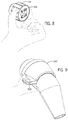
- FIG. 8 is a perspective view exhibiting the user manually activating the example latching system of FIG. 1A .
- FIG. 9 is a perspective view exhibiting the user utilizing a force actuation interface mechanism.
- Some of the problems with some of the known prior art mentioned above include: connectors, particularly electrical connectors tend to have a high mating and unmating force.
- Physical latches can be hard to disengage due to the size of any kind of connector. Physical latches also take up a lot of space that some designs do not have. Latches can wear out and fail to hold connection and maintain necessary connective force. Latches can also have an issue with ease of use for both engaging and disengaging as well as alignment to ensure the latch is in the proper position.
- the example latching systems disclosed herein have nearly unlimited cycle life with consistent retention, and are easy to mate and unmate. More specifically, the act of latching is easier with the presently disclosed magnet latches because the attraction of unlike magnetic poles help to align and pull connectors together, which makes it easy to mate.
- the arrangement of the magnets with alternating poles is a pattern which allows the force to be switched between attraction and repulsion as needed. The repulsion of like magnetic poles can then be used to push connectors away from each other, which makes it easier to unmate.
- By putting magnets in a circular pattern some of the examples disclosed below can help to reduce the overall size of latch without sacrificing the strength of latch.
- alternate magnetic poles are allocated in a circular pattern in the example shown in FIG. 1A and are arranged with a magnetic orientation that makes this latching system unique.
- Circular pattern was chosen instead of others to provide the maximum latch strength with the most compact size, but other examples are shown and discussed below as may be more beneficial to a specific user's needs.
- the example device utilizes both the attraction and repulsion characteristics of magnets in one single application, and also allows the force to be easily switched between attraction and repulsion as needed by simple rotation, translation, or other movement of the latching portion of the connector.
- the latch in one example of the present latching system is external to the connector which is more accessible by hand for rotation to unlatch. This eliminates the need for additional mechanism connected internally for unlatching, which allows the latch to have a more compact size and lower manufacturing cost due to less components involved.
- FIGS. 1A and 1B show two examples of a pair of connectors which embody one example of the convertible force latching system according to the teachings of the present disclosure.
- the latching system in this example is comprised of two matched connector bodies, shown in FIG. 1A as first connector body 102 and second connector body 104 .
- the first and second connector body 102 , 104 are connected at mating surfaces 106 , 108 thereby coupling the respective electrical connectors 110 .
- the first and second connector bodies 102 , 104 are adapted to be mated with complementary shaping as such that the form of the first connector body 102 securely accepts the projections of the second connector body 104 within a recess.
- the coupling of the first and second connectors 102 , 104 in some examples is a slight press fit such that the connectors cannot move relative to one another when connected.
- first and second connector bodies 102 , 104 have at least two possible subsections: a connecting portion 112 housing the electrical contacts 110 and latch portion 114 .
- the latching portion 114 is usually positioned around the connecting portion 112 .
- the second connecting body 104 has a moving latching portion 114 .
- the latching portion may slide to translate linearly or move by any other suitable means as one of ordinary skill in the art would comprehend.
- the first and second connector bodies 102 and 104 each have mating faces 106 and 108 , respectively, positioned around electrical contacts 110 .
- electrical contacts 110 in the example shown are but one of many configurations that can be used. Any number of electrical connections of various gauges and arrangements thereof can be accommodated in each connector body 102 , 104 .
- teachings of this disclosure could equally be applied to other types of releasable connections like data, fluid transfer, or other suitable connections.
- the connector bodies are adapted to swap the connections enabled inside, allowing different electrical connectors to be inserted for example.
- each connector body 102 , 104 as a part of the latching portion 114 there are magnets positioned just under the mating faces 106 , 108 .
- the latching portion 114 can move relative to the connecting portion 112 .
- the rotation of the latching portion 114 in this example allows the magnets on one connecting body 104 to be repositioned relative to the other connecting body 102
- the magnets can be any type of magnet, such as permanently magnetized ferromagnetic materials or rare earth magnets.
- an electromagnet could be used to selectively engage or reverse the magnetic poles.
- each magnet regardless of its shape and attendant magnetic field, has a north and south pole.
- the magnet orientation is based on how the poles are positioned within the magnet and their relative organization when the magnet is installed in the connector body 102 , 104 .
- a magnet is termed to be facing up if the north pole of that magnet is closest to the respective mating surface 106 or 108 and a magnet is termed to be facing down if the south pole of the magnet is closest to the mating surface 106 or 108 .
- the illustrated green circle represents North Magnetic Pole and the purple circle represents South Magnetic Pole for visualization only.
- Magnets are exposed in FIGS. 2 and 3 for illustrated purpose only, but are enclosed in some examples by a cover 600 with screws 602 as shown in FIGS. 6-7 . Magnets may be exposed, partially exposed, or fully enclosed and retained by any other means as desired.
- each of the series of magnets are placed in an alternating pattern. This pattern is repeated in a similar manner on the opposite connector body 104 as in the connector body 102 .
- the magnets are placed in a circular pattern on the connector body 102 with the north poles of the first series of magnets closest to the mating surface 106 , facing “up”, and the south poles of the second series of magnets closest to the mating surface 106 , facing “down”.
- the arrangement enables different uses depending on the relative arrangements of the magnets on one connecting body to the other depending on the position of the moving latching portion 114 .
- a first arrangement illustrated in FIG. 3 , the magnets in the respective alternating series on each connector body 102 , 104 with opposite poles are facing each other to assist in holding the latching system 100 together.
- the first and second series of magnets are aligned with the third and fourth series of magnets, respectively, in a first position such that the first and second series of magnets are attracted to the third and fourth series of magnets.
- the latching portion 114 can be moved in along a predetermined motion path to alter the alignments of the magnets.
- the latching portion can be rotated to shift the magnets in each series 202 and 204 from facing opposite magnetic poles to facing identical charged magnetic poles to the position shown in FIG. 4 .
- the repulsion of the similar poles assists in decoupling the latching system 100 .
- the second arrangement illustrated in FIG. 4 has the first and second series of magnets aligned with the fourth and third series of magnets, respectively, in a second position such that the first and second series of magnets are repelled by the third and fourth series of magnets.
- a locking mechanism can be added to prevent rotation when not desired by the user.
- the connection allows for assistive coupling and decoupling.
- the attraction of unlike magnetic poles from both connector bodies 102 , 104 automatically pulls the parts together which makes them easy to mate.
- the magnets on connector bodies 102 , 104 do not line up perfectly, as the latches get close to each other, the repulsion of magnets pushes like magnetic poles away from each other and the attraction of magnets pulls unlike magnetic poles together.
- This push/pull effect forces Latch 2 to rotate automatically and align all magnets in Latch 2 to Latch 1 for mating.
- the combination of attraction for all magnet pairs also acts as retention to keep the parts mated.
- the attraction helps correctly seat the connector bodies within each other.
- the repulsion helps push the connectors apart. Rather than requiring the user to apply sufficient force, the magnets thereby increasing the user ability to couple these connectors by reducing the force needed to couple the connectors.
- the latch portion 114 is external to the connector body which is accessible by hand for rotation to unlatch, for any size of a scalable latching system 100 .
- Such an example latching system 100 is shown used in FIG. 8 .
- the connector body 104 further includes a force actuation interface mechanism such as a handle or tab to more easily utilize the latching portion 114 .
- Such an example latching system 100 is shown in FIG. 1B and used in FIG. 9 a second connector body 104 ′ with handle 902 .
- Motion of the latching portion 114 of the connector body 104 shown in FIG. 3 is restrained in the example shown by a series of motion guides including a motion stop 502 .
- the stop 502 is a projection from second connector body 104 that fits into a matching recess 504 in the second connector body 104 .
- the shape and size of the stop 502 and recess 504 are determined to allow the shifting of the magnets between each of the alignments discussed above. For example, when the latching system 100 is rotated to the position shown in FIG. 4 , the stop 502 and recess 504 together with the shaping of the connector bodies 102 and 104 themselves form a predetermined motion path which directs and guides user interaction along the proper shift between the attracting position and repelling position. After rotation, all magnets in corresponding connector body 102 have same exact poles as the corresponding mating magnets in corresponding connector body 104 .
- both connector bodies 102 , 104 have rotational alignment features 300 as shown.
- Rotational alignment features such as the features shown in FIG. 1A are included in some examples added to the connector bodies 102 , 104 to prevent them from mating in the wrong orientation.
- the alignment feature changes the mating surface from a perfect round shape to a “D” shape.
- the flat on the “D” shape interferes with the round when the two connectors are mated in the wrong orientation. They can only be mated while the flats align with each other.
- the alignment features can be in any other forms, shapes or means as desired.
- the arrangement of the series of magnets 202 , 204 can include many combinations of size, shape and total number of magnets used and can vary based on application. The size and total number of screws or any other suitable fasteners used can also vary based on requirement.
- another example latching system 100 according to the teachings of the presentation could include as little as two magnets oriented in opposite orientations.
- the alternating series of magnets can be arranged in other shapes with repeating patterns of upward and downward facing magnets.
- the magnets are arranged in two rows and the connector bodies 102 , 104 can be shaped to enable translationary motion to alter the alignment of the magnets relative to one another.
- any repeating pattern and combination of restraints would be suitable if used according to the teachings of this disclosure.
Landscapes
- Engineering & Computer Science (AREA)
- Theoretical Computer Science (AREA)
- General Engineering & Computer Science (AREA)
- General Physics & Mathematics (AREA)
- Physics & Mathematics (AREA)
- Software Systems (AREA)
- Computer Security & Cryptography (AREA)
- Computer Networks & Wireless Communication (AREA)
- Health & Medical Sciences (AREA)
- Bioethics (AREA)
- General Health & Medical Sciences (AREA)
- Computer Hardware Design (AREA)
- Signal Processing (AREA)
- Details Of Connecting Devices For Male And Female Coupling (AREA)
Priority Applications (2)
| Application Number | Priority Date | Filing Date | Title |
|---|---|---|---|
| US16/229,121 US10938149B2 (en) | 2017-12-21 | 2018-12-21 | Convertible force latching system |
| US17/173,352 US11539161B2 (en) | 2017-12-21 | 2021-02-11 | Convertible force latching system |
Applications Claiming Priority (2)
| Application Number | Priority Date | Filing Date | Title |
|---|---|---|---|
| US201762608958P | 2017-12-21 | 2017-12-21 | |
| US16/229,121 US10938149B2 (en) | 2017-12-21 | 2018-12-21 | Convertible force latching system |
Related Child Applications (1)
| Application Number | Title | Priority Date | Filing Date |
|---|---|---|---|
| US17/173,352 Continuation US11539161B2 (en) | 2017-12-21 | 2021-02-11 | Convertible force latching system |
Publications (2)
| Publication Number | Publication Date |
|---|---|
| US20190199032A1 US20190199032A1 (en) | 2019-06-27 |
| US10938149B2 true US10938149B2 (en) | 2021-03-02 |
Family
ID=66951541
Family Applications (2)
| Application Number | Title | Priority Date | Filing Date |
|---|---|---|---|
| US16/229,121 Active US10938149B2 (en) | 2017-12-21 | 2018-12-21 | Convertible force latching system |
| US17/173,352 Active 2039-07-12 US11539161B2 (en) | 2017-12-21 | 2021-02-11 | Convertible force latching system |
Family Applications After (1)
| Application Number | Title | Priority Date | Filing Date |
|---|---|---|---|
| US17/173,352 Active 2039-07-12 US11539161B2 (en) | 2017-12-21 | 2021-02-11 | Convertible force latching system |
Country Status (5)
| Country | Link |
|---|---|
| US (2) | US10938149B2 (fr) |
| EP (1) | EP3729480B1 (fr) |
| JP (2) | JP2021507475A (fr) |
| CN (1) | CN111742382B (fr) |
| WO (1) | WO2019126658A1 (fr) |
Cited By (5)
| Publication number | Priority date | Publication date | Assignee | Title |
|---|---|---|---|---|
| US11260711B2 (en) * | 2019-02-21 | 2022-03-01 | Jost-Werke Deutschland Gmbh | Connection device, connection system and tractor-trailer combination |
| US20220144107A1 (en) * | 2020-11-12 | 2022-05-12 | Rivian Ip Holdings, Llc | Automated plug-in system and method |
| US11381033B2 (en) * | 2020-08-06 | 2022-07-05 | Onanon, Inc. | Self-locking connector |
| US20220297798A1 (en) * | 2021-03-16 | 2022-09-22 | Tien Hsin Industries Co., Ltd. | Electronic derailleur |
| US20230108638A1 (en) * | 2021-10-04 | 2023-04-06 | Bunn-O-Matic Corporation | Magnetic light cord for use with a beverage making and dispensing machine |
Families Citing this family (4)
| Publication number | Priority date | Publication date | Assignee | Title |
|---|---|---|---|---|
| US12184957B2 (en) * | 2021-12-20 | 2024-12-31 | Karl Storz Imaging, Inc. | Electrical device with a single interface for accommodating multiple connector types, and a connector kit |
| JP1737239S (ja) * | 2021-12-28 | 2023-02-20 | 車両充電インレット取り付け用ブラケット | |
| DE102022206945A1 (de) * | 2022-07-07 | 2024-01-18 | Richard Wolf Gmbh | Endoskopisches Instrument mit einem Handstück |
| WO2024090164A1 (fr) * | 2022-10-24 | 2024-05-02 | ソニーグループ株式会社 | Dispositif magnétique, structure de connexion magnétique et procédé de connexion magnétique |
Citations (27)
| Publication number | Priority date | Publication date | Assignee | Title |
|---|---|---|---|---|
| US1238345A (en) | 1916-10-04 | 1917-08-28 | Frank A Schoenle | Magnetic latch device. |
| US2609221A (en) | 1949-08-06 | 1952-09-02 | Lab Equipment Corp | Magnetic door catch |
| US2813741A (en) | 1955-10-05 | 1957-11-19 | Gen Electric | Magnetic latch |
| US2877041A (en) | 1955-10-04 | 1959-03-10 | Gen Electric | Magnetic latch for refrigerator door |
| US2877040A (en) | 1954-11-24 | 1959-03-10 | Stanley Works | Magnetic latch |
| US2901278A (en) | 1957-06-17 | 1959-08-25 | Philips Corp | Magnetic latch assembly |
| US2990210A (en) | 1956-06-11 | 1961-06-27 | Ajax Hardware Mfg Corp | Magnetic latch |
| US3276804A (en) | 1964-07-02 | 1966-10-04 | Heppner Mfg Company | Magnetic latch |
| US3345102A (en) | 1966-07-01 | 1967-10-03 | Gen Electric | Magnetic latch assembly |
| US3350127A (en) | 1964-03-24 | 1967-10-31 | Philips Corp | Magnetic latch for a door |
| US3425729A (en) | 1967-11-17 | 1969-02-04 | Southco | Magnetic latch fastener |
| US3492037A (en) | 1968-06-26 | 1970-01-27 | Harold D Hutchinson | Magnetic touch latch |
| US3744833A (en) | 1970-04-15 | 1973-07-10 | D Berducone | Magnetic latch |
| US3794366A (en) | 1972-12-11 | 1974-02-26 | P Graham | Magnetic latch and lock |
| US3984795A (en) | 1976-02-09 | 1976-10-05 | I-T-E Imperial Corporation | Magnetic latch construction |
| US5485733A (en) | 1993-05-13 | 1996-01-23 | Hoffman; Charles G. | Concealed magnetic lock for cabinet closure |
| US5611120A (en) | 1991-05-24 | 1997-03-18 | International Patent Holdings Ltd. | Magnetic latch |
| US5829987A (en) * | 1995-04-01 | 1998-11-03 | Fritsch; Klaus-Dieter | Electromechanical connection device |
| US5909100A (en) | 1996-08-09 | 1999-06-01 | Sumitomo Wiring Systems, Ltd. | Charging connector for electric vehicle |
| US6195898B1 (en) | 1998-12-04 | 2001-03-06 | Adam M. Lemisch | Magnetically latching butterfly knife |
| US20040183313A1 (en) | 2003-03-19 | 2004-09-23 | Sherman Robert A. | Display case with magnetic latch assembly |
| US20110193354A1 (en) | 2010-02-08 | 2011-08-11 | Carl Simmonds | Magnetic gate latch device |
| US20150102879A1 (en) | 2013-10-11 | 2015-04-16 | Olio Devices, Inc. | Wireless electronic device and method of use |
| US20160180999A1 (en) | 2014-12-23 | 2016-06-23 | Qualcomm Incorporated | Electromagnetic mating interface |
| US20160285198A1 (en) * | 2015-03-27 | 2016-09-29 | Foxconn Interconnect Technology Limited | Method of retaining magnets to insulative housing of connector |
| US20170005435A1 (en) | 2010-12-24 | 2017-01-05 | Phitek Systems Ltd. | Magnetic connector apparatus |
| US20170062999A1 (en) | 2015-08-28 | 2017-03-02 | Jean-Michel Andre Thiers | Rotatable Electrical Connector |
Family Cites Families (16)
| Publication number | Priority date | Publication date | Assignee | Title |
|---|---|---|---|---|
| JPS509990B1 (fr) * | 1970-06-01 | 1975-04-17 | ||
| US3790197A (en) | 1972-06-22 | 1974-02-05 | Gen Electric | Magnetic latch |
| JPH10112354A (ja) * | 1996-08-09 | 1998-04-28 | Sumitomo Wiring Syst Ltd | 電気自動車用充電コネクタ |
| EA006279B1 (ru) * | 2001-08-24 | 2005-10-27 | Дзе Осси Кидз Той Компани Пти Лимитед | Переключаемое магнитное устройство |
| US7869974B2 (en) * | 2003-01-15 | 2011-01-11 | Plishner Paul J | Connector or other circuit element having an indirectly coupled integrated circuit |
| JP2009205912A (ja) * | 2008-02-27 | 2009-09-10 | Tokyo Seimitsu Co Ltd | コネクタ |
| US8571366B2 (en) * | 2008-05-09 | 2013-10-29 | Hewlett-Packard Development Company, L.P. | Proximity free space optical interconnect |
| US8348678B2 (en) * | 2010-01-11 | 2013-01-08 | Automotive Industrial Marketing Corp. | Magnetic cable connector systems |
| US8596881B2 (en) * | 2010-12-09 | 2013-12-03 | Microsoft Corporation | Power and data connector |
| KR101265730B1 (ko) * | 2013-02-20 | 2013-05-21 | (주)에스피에스 | 전력공급차단회로를 구비한 마그네틱 커넥터 모듈 |
| US20160003270A1 (en) * | 2013-03-15 | 2016-01-07 | L. Christopher Franklin | Mounting apparatus |
| US9017092B1 (en) * | 2014-05-07 | 2015-04-28 | Microsoft Technology Licensing, Llc | Electronic connector |
| JP6537819B2 (ja) * | 2014-12-18 | 2019-07-03 | 日本航空電子工業株式会社 | コネクタ対 |
| FR3038460B1 (fr) * | 2015-07-01 | 2019-09-13 | Gulplug | Ensemble de prise electrique |
| US10361508B2 (en) * | 2016-03-14 | 2019-07-23 | Drägerwerk AG & Co. KGaA | Docking devices and cable connectors for patient monitoring systems |
| CN106505363B (zh) * | 2016-12-23 | 2019-11-26 | 深圳市泰科汉泽精密电子有限公司 | 磁性电极纽扣 |
-
2018
- 2018-12-21 JP JP2020534359A patent/JP2021507475A/ja active Pending
- 2018-12-21 CN CN201880089982.2A patent/CN111742382B/zh active Active
- 2018-12-21 US US16/229,121 patent/US10938149B2/en active Active
- 2018-12-21 EP EP18892895.6A patent/EP3729480B1/fr active Active
- 2018-12-21 WO PCT/US2018/067116 patent/WO2019126658A1/fr not_active Ceased
-
2021
- 2021-02-11 US US17/173,352 patent/US11539161B2/en active Active
-
2022
- 2022-11-10 JP JP2022180252A patent/JP2023001331A/ja active Pending
Patent Citations (27)
| Publication number | Priority date | Publication date | Assignee | Title |
|---|---|---|---|---|
| US1238345A (en) | 1916-10-04 | 1917-08-28 | Frank A Schoenle | Magnetic latch device. |
| US2609221A (en) | 1949-08-06 | 1952-09-02 | Lab Equipment Corp | Magnetic door catch |
| US2877040A (en) | 1954-11-24 | 1959-03-10 | Stanley Works | Magnetic latch |
| US2877041A (en) | 1955-10-04 | 1959-03-10 | Gen Electric | Magnetic latch for refrigerator door |
| US2813741A (en) | 1955-10-05 | 1957-11-19 | Gen Electric | Magnetic latch |
| US2990210A (en) | 1956-06-11 | 1961-06-27 | Ajax Hardware Mfg Corp | Magnetic latch |
| US2901278A (en) | 1957-06-17 | 1959-08-25 | Philips Corp | Magnetic latch assembly |
| US3350127A (en) | 1964-03-24 | 1967-10-31 | Philips Corp | Magnetic latch for a door |
| US3276804A (en) | 1964-07-02 | 1966-10-04 | Heppner Mfg Company | Magnetic latch |
| US3345102A (en) | 1966-07-01 | 1967-10-03 | Gen Electric | Magnetic latch assembly |
| US3425729A (en) | 1967-11-17 | 1969-02-04 | Southco | Magnetic latch fastener |
| US3492037A (en) | 1968-06-26 | 1970-01-27 | Harold D Hutchinson | Magnetic touch latch |
| US3744833A (en) | 1970-04-15 | 1973-07-10 | D Berducone | Magnetic latch |
| US3794366A (en) | 1972-12-11 | 1974-02-26 | P Graham | Magnetic latch and lock |
| US3984795A (en) | 1976-02-09 | 1976-10-05 | I-T-E Imperial Corporation | Magnetic latch construction |
| US5611120A (en) | 1991-05-24 | 1997-03-18 | International Patent Holdings Ltd. | Magnetic latch |
| US5485733A (en) | 1993-05-13 | 1996-01-23 | Hoffman; Charles G. | Concealed magnetic lock for cabinet closure |
| US5829987A (en) * | 1995-04-01 | 1998-11-03 | Fritsch; Klaus-Dieter | Electromechanical connection device |
| US5909100A (en) | 1996-08-09 | 1999-06-01 | Sumitomo Wiring Systems, Ltd. | Charging connector for electric vehicle |
| US6195898B1 (en) | 1998-12-04 | 2001-03-06 | Adam M. Lemisch | Magnetically latching butterfly knife |
| US20040183313A1 (en) | 2003-03-19 | 2004-09-23 | Sherman Robert A. | Display case with magnetic latch assembly |
| US20110193354A1 (en) | 2010-02-08 | 2011-08-11 | Carl Simmonds | Magnetic gate latch device |
| US20170005435A1 (en) | 2010-12-24 | 2017-01-05 | Phitek Systems Ltd. | Magnetic connector apparatus |
| US20150102879A1 (en) | 2013-10-11 | 2015-04-16 | Olio Devices, Inc. | Wireless electronic device and method of use |
| US20160180999A1 (en) | 2014-12-23 | 2016-06-23 | Qualcomm Incorporated | Electromagnetic mating interface |
| US20160285198A1 (en) * | 2015-03-27 | 2016-09-29 | Foxconn Interconnect Technology Limited | Method of retaining magnets to insulative housing of connector |
| US20170062999A1 (en) | 2015-08-28 | 2017-03-02 | Jean-Michel Andre Thiers | Rotatable Electrical Connector |
Non-Patent Citations (1)
| Title |
|---|
| ISA/US, International Search Report and Written Opinion issued on PCT application No. US18/67116, dated Mar. 26, 2019, 10 pages. |
Cited By (8)
| Publication number | Priority date | Publication date | Assignee | Title |
|---|---|---|---|---|
| US11260711B2 (en) * | 2019-02-21 | 2022-03-01 | Jost-Werke Deutschland Gmbh | Connection device, connection system and tractor-trailer combination |
| US11381033B2 (en) * | 2020-08-06 | 2022-07-05 | Onanon, Inc. | Self-locking connector |
| US11710926B2 (en) | 2020-08-06 | 2023-07-25 | Onanon, Inc. | Self-locking connector |
| US12368266B2 (en) | 2020-08-06 | 2025-07-22 | Onanon, Inc. | Self-locking connector |
| US20220144107A1 (en) * | 2020-11-12 | 2022-05-12 | Rivian Ip Holdings, Llc | Automated plug-in system and method |
| US11904715B2 (en) * | 2020-11-12 | 2024-02-20 | Rivian Ip Holdings, Llc | Automated plug-in system and method |
| US20220297798A1 (en) * | 2021-03-16 | 2022-09-22 | Tien Hsin Industries Co., Ltd. | Electronic derailleur |
| US20230108638A1 (en) * | 2021-10-04 | 2023-04-06 | Bunn-O-Matic Corporation | Magnetic light cord for use with a beverage making and dispensing machine |
Also Published As
| Publication number | Publication date |
|---|---|
| EP3729480A1 (fr) | 2020-10-28 |
| CN111742382A (zh) | 2020-10-02 |
| CN111742382B (zh) | 2023-01-06 |
| US11539161B2 (en) | 2022-12-27 |
| WO2019126658A1 (fr) | 2019-06-27 |
| JP2021507475A (ja) | 2021-02-22 |
| JP2023001331A (ja) | 2023-01-04 |
| EP3729480A4 (fr) | 2022-01-05 |
| US20210173947A1 (en) | 2021-06-10 |
| EP3729480B1 (fr) | 2025-07-09 |
| US20190199032A1 (en) | 2019-06-27 |
Similar Documents
| Publication | Publication Date | Title |
|---|---|---|
| US10938149B2 (en) | Convertible force latching system | |
| JP7381664B2 (ja) | 磁気バックル組立体 | |
| CN103957739B (zh) | 锁紧设备 | |
| US4099755A (en) | Releasable magnet assembly | |
| US8454063B2 (en) | Mode-switchable door strike | |
| CN103563018B (zh) | 磁性固定件和连接件 | |
| CN106030926B (zh) | 具有卡合部件的插拔连接器部件 | |
| US10347408B2 (en) | Magnetic fixings and connectors | |
| US7361045B1 (en) | Locking device for an electrical receptacle | |
| US20060174455A1 (en) | Magnetically actuated locking mechanism | |
| EP3729479B1 (fr) | Actionneur comprenant un aimant électropermanent et procédé | |
| US9806459B2 (en) | Plug connector part with a latching element | |
| EP2599943A1 (fr) | Dispositif de verrouillage électronique de portière pour coupler facilement un embrayage | |
| WO2021004457A1 (fr) | Dispositif de fixation magnétique | |
| CN112854911B (zh) | 一种电子锁的空转离合机构以及具有其的电子锁 | |
| US20020149208A1 (en) | Latch mechanism | |
| EP1950370A1 (fr) | Dispositif de verrouillage pour portes, volets et similaires | |
| CN103608537B (zh) | 磁性排斥锁组件 | |
| CN220069030U (zh) | 一种锁扣装置及穿戴设备 | |
| US20250257588A1 (en) | Magnetically Coded Lock | |
| CN213393793U (zh) | 一种离合装置 | |
| CN120938200A (zh) | 磁性扣具 | |
| US20230400749A1 (en) | Lens Cap | |
| CN117905936A (zh) | 一种双控阀 | |
| CN115045924A (zh) | 一种电磁离合器及核反应堆 |
Legal Events
| Date | Code | Title | Description |
|---|---|---|---|
| AS | Assignment |
Owner name: IDEAL INDUSTRIES, INC., ILLINOIS Free format text: PATENT ASSIGNMENT;ASSIGNORS:LI, JIA YONG;PETERSON, BRIAN ROBERT;REEL/FRAME:047973/0771 Effective date: 20181220 |
|
| FEPP | Fee payment procedure |
Free format text: ENTITY STATUS SET TO UNDISCOUNTED (ORIGINAL EVENT CODE: BIG.); ENTITY STATUS OF PATENT OWNER: LARGE ENTITY |
|
| STPP | Information on status: patent application and granting procedure in general |
Free format text: NON FINAL ACTION MAILED |
|
| STPP | Information on status: patent application and granting procedure in general |
Free format text: RESPONSE TO NON-FINAL OFFICE ACTION ENTERED AND FORWARDED TO EXAMINER |
|
| STPP | Information on status: patent application and granting procedure in general |
Free format text: DOCKETED NEW CASE - READY FOR EXAMINATION |
|
| STPP | Information on status: patent application and granting procedure in general |
Free format text: NOTICE OF ALLOWANCE MAILED -- APPLICATION RECEIVED IN OFFICE OF PUBLICATIONS |
|
| STCF | Information on status: patent grant |
Free format text: PATENTED CASE |
|
| AS | Assignment |
Owner name: JPMORGAN CHASE BANK, N.A., AS ADMINISTRATIVE AGENT, ILLINOIS Free format text: SECURITY INTEREST;ASSIGNORS:IDEAL INDUSTRIES, INC.;ANDERSON POWER PRODUCTS, INC.;REEL/FRAME:066358/0354 Effective date: 20240119 |
|
| MAFP | Maintenance fee payment |
Free format text: PAYMENT OF MAINTENANCE FEE, 4TH YEAR, LARGE ENTITY (ORIGINAL EVENT CODE: M1551); ENTITY STATUS OF PATENT OWNER: LARGE ENTITY Year of fee payment: 4 |