US11045654B2 - Tissue conduction communication using ramped drive signal - Google Patents
Tissue conduction communication using ramped drive signal Download PDFInfo
- Publication number
- US11045654B2 US11045654B2 US16/204,172 US201816204172A US11045654B2 US 11045654 B2 US11045654 B2 US 11045654B2 US 201816204172 A US201816204172 A US 201816204172A US 11045654 B2 US11045654 B2 US 11045654B2
- Authority
- US
- United States
- Prior art keywords
- signal
- tcc
- ramp
- peak
- transmitter
- Prior art date
- Legal status (The legal status is an assumption and is not a legal conclusion. Google has not performed a legal analysis and makes no representation as to the accuracy of the status listed.)
- Active, expires
Links
Images



Classifications
-
- A—HUMAN NECESSITIES
- A61—MEDICAL OR VETERINARY SCIENCE; HYGIENE
- A61N—ELECTROTHERAPY; MAGNETOTHERAPY; RADIATION THERAPY; ULTRASOUND THERAPY
- A61N1/00—Electrotherapy; Circuits therefor
- A61N1/18—Applying electric currents by contact electrodes
- A61N1/32—Applying electric currents by contact electrodes alternating or intermittent currents
- A61N1/36—Applying electric currents by contact electrodes alternating or intermittent currents for stimulation
- A61N1/372—Arrangements in connection with the implantation of stimulators
- A61N1/37211—Means for communicating with stimulators
- A61N1/37217—Means for communicating with stimulators characterised by the communication link, e.g. acoustic or tactile
-
- A—HUMAN NECESSITIES
- A61—MEDICAL OR VETERINARY SCIENCE; HYGIENE
- A61N—ELECTROTHERAPY; MAGNETOTHERAPY; RADIATION THERAPY; ULTRASOUND THERAPY
- A61N1/00—Electrotherapy; Circuits therefor
- A61N1/18—Applying electric currents by contact electrodes
- A61N1/32—Applying electric currents by contact electrodes alternating or intermittent currents
- A61N1/36—Applying electric currents by contact electrodes alternating or intermittent currents for stimulation
- A61N1/372—Arrangements in connection with the implantation of stimulators
- A61N1/37211—Means for communicating with stimulators
- A61N1/37252—Details of algorithms or data aspects of communication system, e.g. handshaking, transmitting specific data or segmenting data
- A61N1/37288—Communication to several implantable medical devices within one patient
-
- A—HUMAN NECESSITIES
- A61—MEDICAL OR VETERINARY SCIENCE; HYGIENE
- A61N—ELECTROTHERAPY; MAGNETOTHERAPY; RADIATION THERAPY; ULTRASOUND THERAPY
- A61N1/00—Electrotherapy; Circuits therefor
- A61N1/18—Applying electric currents by contact electrodes
- A61N1/32—Applying electric currents by contact electrodes alternating or intermittent currents
- A61N1/36—Applying electric currents by contact electrodes alternating or intermittent currents for stimulation
- A61N1/372—Arrangements in connection with the implantation of stimulators
- A61N1/375—Constructional arrangements, e.g. casings
- A61N1/3756—Casings with electrodes thereon, e.g. leadless stimulators
-
- A—HUMAN NECESSITIES
- A61—MEDICAL OR VETERINARY SCIENCE; HYGIENE
- A61N—ELECTROTHERAPY; MAGNETOTHERAPY; RADIATION THERAPY; ULTRASOUND THERAPY
- A61N1/00—Electrotherapy; Circuits therefor
- A61N1/18—Applying electric currents by contact electrodes
- A61N1/32—Applying electric currents by contact electrodes alternating or intermittent currents
- A61N1/38—Applying electric currents by contact electrodes alternating or intermittent currents for producing shock effects
- A61N1/39—Heart defibrillators
- A61N1/3956—Implantable devices for applying electric shocks to the heart, e.g. for cardioversion
-
- A—HUMAN NECESSITIES
- A61—MEDICAL OR VETERINARY SCIENCE; HYGIENE
- A61N—ELECTROTHERAPY; MAGNETOTHERAPY; RADIATION THERAPY; ULTRASOUND THERAPY
- A61N1/00—Electrotherapy; Circuits therefor
- A61N1/02—Details
- A61N1/04—Electrodes
- A61N1/05—Electrodes for implantation or insertion into the body, e.g. heart electrode
-
- A—HUMAN NECESSITIES
- A61—MEDICAL OR VETERINARY SCIENCE; HYGIENE
- A61N—ELECTROTHERAPY; MAGNETOTHERAPY; RADIATION THERAPY; ULTRASOUND THERAPY
- A61N1/00—Electrotherapy; Circuits therefor
- A61N1/18—Applying electric currents by contact electrodes
- A61N1/32—Applying electric currents by contact electrodes alternating or intermittent currents
- A61N1/36—Applying electric currents by contact electrodes alternating or intermittent currents for stimulation
- A61N1/372—Arrangements in connection with the implantation of stimulators
- A61N1/37211—Means for communicating with stimulators
- A61N1/37252—Details of algorithms or data aspects of communication system, e.g. handshaking, transmitting specific data or segmenting data
- A61N1/37264—Changing the program; Upgrading firmware
-
- A—HUMAN NECESSITIES
- A61—MEDICAL OR VETERINARY SCIENCE; HYGIENE
- A61N—ELECTROTHERAPY; MAGNETOTHERAPY; RADIATION THERAPY; ULTRASOUND THERAPY
- A61N1/00—Electrotherapy; Circuits therefor
- A61N1/18—Applying electric currents by contact electrodes
- A61N1/32—Applying electric currents by contact electrodes alternating or intermittent currents
- A61N1/38—Applying electric currents by contact electrodes alternating or intermittent currents for producing shock effects
- A61N1/39—Heart defibrillators
- A61N1/3975—Power supply
Definitions
- the disclosure relates generally to devices, systems and methods for communicating using tissue conduction communication.
- TCC tissue conduction communication
- HBC human body conduction
- IMDs implantable medical devices
- Examples include IMDs that deliver therapy to and/or monitor conditions associated with the heart, muscle, nerve, brain, stomach or other tissue.
- Some therapies include the delivery of electrical stimulation to such tissues.
- Some IMDs may employ electrodes for the delivery of therapeutic electrical signals to such organs or tissues, electrodes for sensing intrinsic physiological electrical signals within the patient, which may be propagated by such organs or tissue, and/or other sensors for sensing physiological signals of a patient.
- Implantable cardioverter defibrillators may be used to deliver high energy defibrillation and/or cardioversion shocks to a patient's heart when atrial or ventricular tachyarrhythmia, e.g., tachycardia or fibrillation, is detected.
- An ICD may detect a tachyarrhythmia based on an analysis of a cardiac electrogram sensed via electrodes, and may deliver anti-tachyarrhythmia shocks, e.g., defibrillation shocks and/or cardioversion shocks, via electrodes.
- extracardiovascular ICD systems are not coupled to any transvenous leads, and instead sense and deliver shocks via electrodes implanted away from the patient's heart, e.g., implanted subcutaneously or substernally.
- the extra-cardiovascular electrodes may be provided along the housing of the subcutaneous ICD and/or coupled to the housing via one or more leads extending subcutaneously, submuscularly or substernally from the housing.
- the techniques of this disclosure generally relate to TCC signal transmission techniques performed by a device.
- the techniques of this disclosure are described in the context of an IMD. However, the techniques can be utilized by any device, medical or non-medical, implanted or external, that communicates using TCC.
- a TCC transmitter included in a transmitting IMD is configured to generate at least one beacon signal during a wakeup mode of the TCC transmitter and transmit data signals during a data transmission mode of the TCC transmitter.
- a TCC transmitter operating according to the techniques disclosed herein is configured to transmit a ramp on signal to charge an alternating current (AC) coupling capacitor prior to transmitting a TCC signal, e.g., at the beginning of a TCC transmission session, to minimize interference of the TCC signal with electrical signal sensing circuitry in the IMD system.
- the TCC transmitter may be controlled to produce a ramp off signal to control discharge of the coupling capacitor after a TCC signal, e.g., at the end of a TCC transmission session.
- the disclosure provides a method comprising generating, with a tissue conduction communication (TCC) transmitter, a TCC ramp on signal having a peak-to-peak amplitude that is stepped up from a starting peak-to-peak amplitude to an ending peak-to-peak amplitude according to a step increment and a step up interval, transmitting, with the TCC transmitter, the TCC ramp on signal via a coupling capacitor coupled to a transmitting electrode vector, and transmitting, with the TCC transmitter, a second TCC signal after the TCC ramp on signal.
- TCC tissue conduction communication
- FIG. 1 is a conceptual diagram of an IMD system capable of TCC according to one example.
- FIG. 3B is a schematic diagram of circuitry that may be included in the pacemaker of FIG. 3A according to one example.
- FIG. 4 illustrates a perspective view of a leadless pressure sensor according to one example.
- FIG. 5 is a schematic diagram of an ICD capable of transmitting TCC signals according to one example.
- FIG. 6 is a conceptual diagram illustrating an example configuration of a TCC transmitter that may be included in the ICD of FIG. 5 or in the pacemaker of FIG. 3B or pressure sensor of FIG. 4 .
- FIG. 7 is a conceptual diagram of a TCC transmission session that may be executed by the TCC transmitter of FIG. 6 .
- FIG. 8 is a diagram of operations performed by an IMD system during the wakeup mode of the TCC transmitter of FIG. 6 .
- FIG. 9 is a diagram of a TCC ramp on signal, beacon signal, and ramp off signal according to one example.
- FIG. 10 is a diagram of one example of a transmission session performed by a transmitting device of an IMD system.
- FIG. 11 is a diagram of a data packet that may be transmitted during the data transmission mode of FIG. 10 by the transmitting device according to one example.
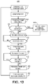
- FIG. 13 is a flow chart of a method for transmitting TCC signals that may be performed by an IMD system according to one example.
- FIG. 14 is a conceptual diagram of a method for transmitting TCC signals during multiple transmission sessions according to one example.
- TCC signals may be wirelessly transmitted from one IMD to one or more IMDs co-implanted within a patient and/or to an external medical device having skin or surface electrodes coupled to the patient for transmitting and/or receiving TCC signals.
- Some IMDs and external medical devices may be configured to sense an electrophysiological signal via sensing electrodes and/or monitor electrical impedance such as transthoracic impedance signals. Examples of electrophysiological signals include a cardiac electrical signal produced by the patient's heart, an electromyogram signal produced by skeletal muscle tissue, and other electrophysiological signals produced by the brain, nerve or muscle tissue. Transmission of a communication signal through body tissue may cause interference with electrical signal sensing circuitry and/or may unintentionally cause electrical stimulation of muscle or nerves depending on the amplitude and frequency of the transmitted signal.
- the TCC signal transmission techniques may also reduce the likelihood that another IMD implanted in patient 12 that is configured to sense electrophysiological signals, such as R-waves and/or P-waves, falsely senses TCC signals as physiological signals.
- Another IMD implanted in patient 12 may be the intended receiving device of the transmitted TCC signals, e.g., pacemaker 100 receiving signals from ICD 14 or vice versa.
- another IMD co-implanted in patient 12 may not be the receiving device of transmitted TCC signals but may be configured to sense electrophysiological signals via electrodes coupled to the co-implanted IMD.
- a voltage signal may develop across sensing electrodes of the intended or unintended receiving device and interfere with electrophysiological sensing and event detection.
- the TCC signal transmission techniques of the present disclosure may reduce or eliminate the incidence of TCC signals being sensed as electrophysiological signals or events by any other IMD implanted in patient 12 or an external device having electrodes coupled to the patient externally.
- ICD 14 includes a connector assembly 17 (also referred to as a connector block or header) that includes electrical feedthroughs crossing housing 15 to provide electrical connections between conductors extending within the lead body 18 of lead 16 and electronic components included within the housing 15 of ICD 14 .
- housing 15 may house one or more processors, memories, transceivers, cardiac electrical signal sensing circuitry, therapy delivery circuitry, TCC transmitting and receiving circuitry, power sources and other components for sensing cardiac electrical signals, detecting a heart rhythm, and controlling and delivering electrical stimulation pulses to treat an abnormal heart rhythm and for transmitting TCC signals to pacemaker 100 and/or receiving TCC signals from pacemaker 100 .
- Lead 16 includes an elongated lead body 18 having a proximal end 27 that includes a lead connector (not shown) configured to be connected to ICD connector assembly 17 and a distal portion 25 that includes one or more electrodes.
- the distal portion 25 of lead body 18 includes defibrillation electrodes 24 and 26 and pace/sense electrodes 28 and 30 .
- defibrillation electrodes 24 and 26 may together form a defibrillation electrode in that they may be configured to be activated concurrently.
- defibrillation electrodes 24 and 26 may form separate defibrillation electrodes in which case each of the electrodes 24 and 26 may be selectively activated independently.
- Electrodes 24 and 26 are referred to herein as defibrillation electrodes because they are utilized, individually or collectively, for delivering high voltage stimulation therapy (e.g., cardioversion or defibrillation shocks). Electrodes 24 and 26 may be elongated coil electrodes and generally have a relatively high surface area for delivering high voltage electrical stimulation pulses compared to pacing and sensing electrodes 28 and 30 . However, electrodes 24 and 26 and housing 15 may also be utilized to provide pacing functionality, sensing functionality, and/or TCC signal transmission and receiving in addition to or instead of high voltage stimulation therapy.
- high voltage stimulation therapy e.g., cardioversion or defibrillation shocks.
- Electrodes 24 and 26 may be elongated coil electrodes and generally have a relatively high surface area for delivering high voltage electrical stimulation pulses compared to pacing and sensing electrodes 28 and 30 . However, electrodes 24 and 26 and housing 15 may also be utilized to provide pacing functionality, sensing functionality, and/or TCC signal transmission
- electrodes 24 and 26 may be used in a sensing vector used to sense cardiac electrical signals and detect and discriminate tachyarrhythmias. Electrodes 24 and 26 may be used in a TCC signal transmitting electrode vector in combination with each other, collectively with housing 15 , or individually with housing 15 . In the case of ICD 14 being configured to receive TCC signals from pacemaker 100 , electrodes 24 , 26 and/or housing 15 may be used in a TCC receiving electrode vector. The transmitting and receiving electrode vectors may be the same or different vectors.
- Electrodes 28 and 30 are relatively smaller surface area electrodes which are available for use in sensing electrode vectors for sensing cardiac electrical signals and may be used for delivering relatively low voltage pacing pulses in some configurations. Electrodes 28 and 30 are referred to as pace/sense electrodes because they are generally configured for use in low voltage applications, e.g., delivery of relatively low voltage pacing pulses and/or sensing of cardiac electrical signals, as opposed to delivering high voltage cardioversion defibrillation shocks. In some instances, electrodes 28 and 30 may provide only pacing functionality, only sensing functionality or both. Furthermore, one or both of electrodes 28 and 30 may be used in TCC signal transmitting and/or receiving in some examples, e.g., in conjunction with electrodes 24 , 26 and/or housing electrode 15 .
- ICD 14 may obtain cardiac electrical signals corresponding to electrical activity of heart 8 via a combination of sensing electrode vectors that include combinations of electrodes 24 , 26 , 28 , 30 and/or housing 15 .
- Various sensing electrode vectors utilizing combinations of electrodes 24 , 26 , 28 , and 30 may be selected by sensing circuitry included in ICD 14 for receiving a cardiac electrical signal via one or more sensing electrode vectors.
- a TCC transmitting electrode vector may be selected from defibrillation electrodes 24 , 26 , 28 , 30 and housing 15 for transmitting TCC signals produced by a TCC transmitter included in ICD 14 . Electrodes, such as defibrillation electrodes 24 and 26 and housing 15 , having a relatively large surface area may be used to transmit TCC signals to minimize the impedance of the transmitting electrode vector. A low impedance of the transmitting electrode vector maximizes the injected current signal.
- the TCC transmitting electrode vector may be selected to both minimize impedance of the transmitting electrode vector and maximize transimpedance from the transmitting electrode vector to the intended receiving electrode vector.
- the term “transimpedance” refers to the voltage received at a TCC signal receiving electrode vector divided by the transmitted current (voltage out divided by current in).
- the transimpedance for a given TCC communication electrode vector for each of two IMDs configured to communicate bidirectionally is the same for communication in both directions for a given set of transmitting and receiving electrode vectors.
- the voltage signal at the intended receiving electrodes is maximized for a given current signal injected into the tissue conductance pathway.
- a low impedance of the transmitting electrode vector and high transimpedance of the TCC pathway increases the received TCC signal strength (voltage signal) at the receiving electrode vector.
- a substantially parallel electrical configuration of the transmitting and receiving electrode vectors relatively wide spacing of the transmitting electrodes, relatively wide spacing of the receiving electrodes, and close proximity of the transmitting electrode vector to the receiving electrode vector.
- a transmitting electrode vector closer in proximity to the receiving electrode vector improves the strength of the TCC signal compared to a larger separation of the transmitting and receiving electrode vectors.
- the optimal orientation for the receiving electrode vector is parallel to the conductive tissue pathway of the current flow.
- a transmitting electrode vector that is substantially electrically parallel to the receiving electrode vector improves the strength of the TCC signal compared to the receiving electrode vector being orthogonal to the pathway of the current flow through the body tissue, which may result in a null signal.
- the TCC transmitting electrode vector may include one or more electrodes coupled to a cardiac electrical event detector included in ICD 14 .
- a transmitting electrode vector may include electrodes coupled to the ICD sensing circuitry when the resulting transmitting electrode vector is optimal in other ways, e.g., low impedance and high transimpedance. Transmission of TCC signals using one or both electrodes included in a sensing electrode vector coupled to a cardiac event detector may be selected in a trade-off for optimizing other considerations in achieving reliable TCC signal transmission and reception.
- TCC signal transmission techniques disclosed herein may reduce or eliminate interference of the TCC signal transmission with cardiac event (or other electrophysiological signal) sensing as well as other sensing functions such as electrical impedance monitoring of a medical electrical lead or body tissue.
- defibrillation electrode 24 may be selected in combination with housing 15 for transmitting TCC signals to pacemaker 100 .
- TCC signals may be transmitted by ICD 14 using defibrillation electrode 26 and housing 15 or using two defibrillation electrodes 24 and 26 .
- the transmitting electrode vector impedance (delivered voltage divided by delivered current) may be up to hundreds of ohms.
- the transimpedance of the TCC pathway that includes a transmitting electrode vector including one defibrillation electrode 24 or 26 paired with housing 15 may be less than 10 ohms and even less than 1 ohm.
- a high transimpedance at the TCC signal transmission frequency is desired to produce a relatively high voltage on the receiving electrodes for a given injected current of the TCC signal.
- lead 16 extends subcutaneously or submuscularly over the ribcage 32 medially from the connector assembly 27 of ICD 14 toward a center of the torso of patient 12 , e.g., toward xiphoid process 20 of patient 12 .
- lead 16 bends or turns and extends superior subcutaneously or submuscularly over the ribcage and/or sternum or substernally under the ribcage and/or sternum 22 .
- Electrical conductors extend through one or more lumens of the elongated lead body 18 of lead 16 from the lead connector at the proximal lead end 27 to electrodes 24 , 26 , 28 , and 30 located along the distal portion 25 of the lead body 18 .
- the elongated electrical conductors contained within the lead body 18 are each electrically coupled with respective defibrillation electrodes 24 and 26 and pace/sense electrodes 28 and 30 , which may be separate respective insulated conductors within the lead body 18 .
- the respective conductors electrically couple the electrodes 24 , 26 , 28 , and 30 to circuitry of ICD 14 , such as a signal generator for therapy delivery and TCC signal transmission and/or a sensing circuit for sensing cardiac electrical signals and/or receiving TCC signals, via connections in the connector assembly 17 , including associated electrical feedthroughs crossing housing 15 .
- the lead body 18 of lead 16 may be formed from a non-conductive material and shaped to form one or more lumens within which the one or more conductors extend.
- Lead body 18 may be a flexible lead body that conforms to an implant pathway. In other examples, lead body 18 may include one or more preformed curves.
- Various example configurations of extra-cardiovascular leads and electrodes and dimensions that may be implemented in conjunction with the TCC transmission techniques disclosed herein are described in pending U.S. Publication No. 2015/0306375 (Marshall, et al.) and pending U.S. Publication No. 2015/0306410 (Marshall, et al.), both of which are incorporated herein by reference in their entirety.
- Pacemaker 100 is shown as a leadless intracardiac pacemaker configured to receive TCC signals from ICD 14 via housing-based electrodes in the examples presented herein and may be configured to transmit TCC signals via housing-based electrodes to ICD 14 , examples of which are illustrated in FIG. 3A and the associated description.
- Pacemaker 100 may be delivered transvenously and anchored by a fixation member at an intracardiac pacing and sensing site.
- pacemaker 100 may be implanted in an atrial or ventricular chamber of the patient's heart.
- pacemaker 100 may be attached to an external surface of heart 8 (e.g., in contact with the epicardium) such that pacemaker 100 is disposed outside of heart 8 .
- FIG. 2 is a conceptual diagram of an IMD system 200 configured to communicate using TCC transmission techniques disclosed herein according to another example.
- the IMD system 200 of FIG. 2 includes an ICD 214 coupled to a patient's heart 8 via transvenous electrical leads 204 , 206 , and 208 .
- IMD system 200 may include a leadless pacemaker 100 and/or a leadless sensor 50 .
- Sensor 50 is shown as a leadless pressure sensor positioned in the pulmonary artery for monitoring pulmonary arterial pressure.
- Leadless pressure sensor 50 also referred to herein as “pressure sensor” 50 , may be positioned at other intracardiac or arterial locations for monitoring blood pressure.
- the IMD system 200 (or IMD system 10 of FIG.
- wireless sensors may include other wireless sensors performing sensing-only or monitoring-only functions configured to send and/or receive TCC signals to/from ICD 214 (or ICD 14 of FIG. 1 ) and/or pacemaker 100 .
- Other wireless sensors may include, for example, an electrogram (EGM) monitor, electrocardiogram (ECG) monitor, an oxygen monitor, acoustical monitor, accelerometer, bioimpedance monitor, pH monitor, temperature monitor, insulin monitor, or other sensing device including one or any combination of sensors.
- ICD 214 includes a connector block 212 that may be configured to receive the proximal ends of a right atrial (RA) lead 204 , a right ventricular (RV) lead 206 and a coronary sinus (CS) lead 208 , which are advanced transvenously for positioning electrodes for sensing and stimulation in three or all four heart chambers.
- RV lead 206 is positioned such that its distal end is in the right ventricle for sensing RV cardiac signals and delivering pacing or shocking pulses in the right ventricle.
- RV lead 206 is equipped with pacing and sensing electrodes shown as a tip electrode 228 and a ring electrode 230 .
- RV lead 206 is further shown to carry defibrillation electrodes 224 and 226 , which may be elongated coil electrodes used to deliver high voltage CV/DF pulses.
- Defibrillation electrode 224 may be referred to herein as the “RV defibrillation electrode” or “RV coil electrode” because it may be carried along RV lead 206 such that it is positioned substantially within the right ventricle when distal pacing and sensing electrodes 228 and 230 are positioned for pacing and sensing in the right ventricle.
- ICD 214 may be a single-chamber device coupled to RV lead 206 and may be configured to perform the TCC techniques disclosed herein using electrodes 224 , 226 , 228 , and 230 and/or housing 215 in addition to receiving cardiac electrical signals from heart 8 and delivering electrical stimulation therapy to heart 8 .
- RA lead 204 is positioned such that its distal end is in the vicinity of the right atrium and the superior vena cava.
- Lead 204 is equipped with pacing and sensing electrodes 220 and 222 , shown as a tip electrode 220 and a ring electrode 222 spaced proximally from tip electrode 220 .
- the electrodes 220 and 222 provide sensing and pacing in the right atrium and are each connected to a respective insulated conductor within the body of RA lead 206 .
- Each insulated conductor is coupled at its proximal end to a connector carried by proximal lead connector 210 .
- CS lead 208 is advanced within the vasculature of the left side of the heart via the coronary sinus (CS) and a cardiac vein (CV).
- CS lead 208 is shown in FIG. 2 as having one or more electrodes 232 , 234 that may be used in delivering pacing and/or sensing cardiac electrical signals in the left chambers of the heart, i.e., the left ventricle and/or the left atrium.
- the one or more electrodes 232 , 234 of CS lead 208 are coupled to respective insulated conductors within the body of CS lead 208 , which provide connection to the proximal lead connector 218 .
- Electrodes 220 , 222 , 224 , 226 , 228 , 230 , 232 , 234 may be selected by ICD 214 in a TCC electrode vector for transmitting and/or receiving TCC signals.
- housing 215 is selected in a TCC transmitting electrode vector along with a lead-based defibrillation electrode, e.g., RV coil electrode 224 or SVC coil electrode 226 , to provide a low impedance and high transimpedance TCC transmitting electrode vector.
- TCC transmission is performed using the RV coil electrode 224 and the SVC coil electrode 226 .
- an electrode 232 or 234 carried by the CS lead 208 may be selected in combination with housing 215 , RV coil electrode 224 , or SVC coil electrode 226 . It is recognized that numerous TCC transmitting electrode vectors may be available using the various electrodes carried by one or more of leads 204 , 206 and 208 coupled to ICD 214 . In some examples, multiple vectors may be selected to promote transmission via a vector that is substantially parallel to the housing-based electrodes of pacemaker 100 or to receiving electrodes of leadless pressure sensor 50 for transmitting signals to the respective pacemaker 100 or pressure sensor 50 .
- Housing 215 encloses internal circuitry generally corresponding to the various circuits and components described in conjunction with FIG. 5 below, for sensing cardiac signals from heart 8 , detecting arrhythmias, controlling therapy delivery and performing TCC with pacemaker 100 and/or pressure sensor 50 using the techniques disclosed herein. It is recognized that these TCC transmission techniques may be practiced in conjunction with alternative lead and electrode configurations other than those depicted in the examples of FIG. 1 and FIG. 2 .
- Pressure sensor 50 may be implanted in the pulmonary artery of the patient for monitoring the pulmonary arterial pressure as an indication of the hemodynamic status of the patient 12 .
- Pressure sensor 50 may be configured to receive pressure signals via a pressure sensor and receive TCC signals via a TCC receiver coupled to electrodes carried by pressure sensor 50 .
- two or more IMDs may be co-implanted in a patient and communicate via TCC to enable a system level of functionality such as sharing the detection of arrhythmias between devices, synchronized timing of anti-tachyarrhythmia shocks, ATP, and/or post-shock pacing, optimization of the resources (e.g., battery capacity or processing power) available to each device, or sharing or coordination of physiological signal acquisition.
- communication between the ICD 14 or ICD 214 and pacemaker 100 may be used to initiate therapy and/or confirm that therapy should be delivered.
- Communication between ICD 14 or ICD 214 and pressure sensor 50 may be used to initiate pressure signal acquisition and/or retrieval of pressure signal data from pressure sensor 50 .
- ICD 14 or ICD 214 may function as a control device and pacemaker 100 and/or sensor 50 to function as responders. For instance, a TCC signal from ICD 14 or 214 may cause pacemaker 100 to deliver a cardiac pacing pulse or therapy.
- ICD 214 may transmit a TCC command signal to pressure sensor 50 for causing pressure sensor 50 to begin acquiring a pressure signal.
- Pressure sensor 50 may be configured to transmit pressure signal data via TCC to ICD 214 or to external device 40 (shown in FIG. 1 ).
- ICD 214 may transmit a TCC command to pressure sensor 50 to cause pressure sensor 50 to transmit a pressure signal in real time, transmit a pressure signal previously acquired and stored by pressure sensor 50 , or transmit pressure data derived from a pressure signal received by pressure sensor 50 .
- pressure sensor 50 may be configured to transmit pressure signal data via RF telemetry to ICD 214 and/or to an external device, such as device 40 shown in FIG. 1 in response to a TCC command signal received from ICD 214 .
- the transmitting IMD e.g., ICD 14 or 214
- the current spreads through the patient's body, e.g., through the thorax, producing a potential field.
- the receiving IMD e.g., pacemaker 100 or sensor 50 or other implanted or external device
- the receiving electrodes are parallel to the tissue conduction pathway of the injected current to maximize the potential difference developed on the receiving electrode vector.
- the current injected to transmit the TCC signal is of sufficient amplitude to produce a voltage potential that can be detected by an intended receiving IMD but should at the same time not capture excitable body tissue, e.g., causing unintended stimulation of nerve or muscle tissue, possibly leading to muscle contraction, pain or even cardiac capture. Any unintended stimulation of nerve or muscle tissue also likely increases noise received on the sensing electrodes of a device of system 10 or 200 .
- Pacemaker 100 may be an unintended receiver of the transmitted TCC signal.
- the voltage developed across the housing-based electrodes of pacemaker 100 may interfere with a cardiac event detector included in pacemaker 100 .
- a subcutaneous cardiac electrical signal monitor having housing-based electrodes for monitoring a subcutaneously-acquired electrocardiogram (ECG) signal such as the REVEAL LINQTM Insertable Cardiac Monitor (available from Medtronic, Inc., Minneapolis, Minn., USA) may be implanted in a patient having two other IMDs configured to communicate via TCC, such as ICD 214 and pressure sensor 50 .
- the cardiac electrical signal monitor may be an unintended receiver of TCC signals transmitted between ICD 214 and pressure sensor 50 .
- the methods disclosed herein for transmitting TCC signals may eliminate or minimize interference of TCC signals with electrical signal sensing circuitry of other IMDs or external devices in or on the patient, which may be intended or unintended receivers.
- FIG. 3A is a conceptual diagram of pacemaker 100 according to one example.
- pacemaker 100 may be a leadless pacemaker including a housing 150 , housing end cap 158 , distal electrode 160 , proximal electrode 152 , fixation member 162 , and a delivery tool interface member 154 .
- Housing 150 sealed with end cap 158 , encloses and protects the various electrical components within pacemaker 100 .
- Pacemaker 100 is shown including two electrodes 152 and 160 but may include two or more electrodes for delivering cardiac electrical stimulation pulses (such as pacing pulses or ATP), sensing cardiac electrical signals for detecting cardiac electrical events, and for receiving and/or transmitting TCC signals.
- cardiac electrical stimulation pulses such as pacing pulses or ATP
- Electrodes 160 and 152 may be used as a cathode and anode pair for cardiac pacing therapy and receiving and/or transmitting TCC signals.
- electrodes 152 and 160 may be used to detect intrinsic electrical signals from the patient's heart 8 .
- pacemaker 100 may include three or more electrodes, where any two or more of the electrodes may be selected to form a vector for delivery of electrical stimulation therapy, detecting intrinsic cardiac electrical signals from the patient's heart 8 , transmitting TCC signals, and receiving TCC signals.
- two or more of the electrodes may be selected, e.g., via switches, to form a vector for TCC.
- Pacemaker 100 may use multiple vectors for TCC transmission or receiving, for example, to promote a substantially parallel electrical configuration with a TCC transmitting electrode vector of ICD 14 or ICD 214 , which may increase the transimpedance and increase the received voltage signal.
- Fixation member 162 may include multiple tines of a shape memory material that retains a preformed curved shape as shown. During implantation, fixation member 162 may be flexed forward to pierce tissue and elastically flex back towards housing 150 to regain their pre-formed curved shape. In this manner, fixation member 162 may be embedded within cardiac tissue at the implant site. In other examples, fixation member 162 may include helical fixation tines, barbs, hooks or other fixation features.
- Delivery tool interface member 154 may be provided for engaging with a delivery tool used to advance pacemaker 100 to an implant site.
- a delivery tool may be removably coupled to delivery tool interface member 154 for retrieving pacemaker 100 back into a delivery tool if removal or repositioning of pacemaker 100 is required.
- FIG. 3B is a schematic diagram of circuitry that may be enclosed by pacemaker housing 150 according to one example.
- Pacemaker housing 150 may enclose a control circuit 170 , memory 172 , pulse generator 176 , sensing circuit 174 , and a power source 178 .
- Control circuit 170 may include a microprocessor and/or other control circuitry for controlling the functions attributed to pacemaker 100 herein, such as controlling pulse generator 176 to deliver signals via electrodes 152 and 160 and controlling sensing circuit 174 to detect signals from electrical signals received via electrodes 152 and 160 .
- Power source 178 may include one or more rechargeable or non-rechargeable batteries for providing power to control circuit 170 , memory 172 , pulse generator 176 and sensing circuit 174 as needed.
- Control circuit 170 may execute instructions stored in memory 172 and may control pulse generator 176 and sensing circuit 174 according to control parameters stored in memory 172 , such as various timing intervals, pacing pulse parameters and cardiac event sensing parameters.
- Pulse generator 176 generates therapeutic pacing pulses delivered via electrodes 152 and 160 under the control of timing circuitry included in control circuit 170 .
- Pulse generator 176 may include charging circuitry, one or more charge storage devices such as one or more capacitors, and switching circuitry that couples the charge storage device(s) to an output capacitor coupled to electrodes 160 and 152 to discharge the charge storage devices via electrodes 160 and 152 .
- pulse generator includes a TCC transmitter (standalone or as part of a transceiver), such as the transmitter described below in conjunction with FIG. 6 , for generating TCC signals transmitted via electrodes 160 and 152 .
- Power source 178 provides power to the charging circuit of pulse generator 176 and the TCC transmitter when present.
- Pacemaker 100 may be configured for sensing cardiac electrical signals, e.g., R-waves or P-waves, and include a cardiac event detector 173 .
- Intrinsic cardiac electrical events may be detected from an electrical signal produced by the heart and received via electrodes 152 and 160 .
- Cardiac event detector 173 may include filters, amplifiers, an analog-to-digital converter, rectifier, comparator, sense amplifier or other circuitry for detecting cardiac events from a cardiac electrical signal received via electrodes 152 and 160 .
- cardiac event detector 173 may apply various blanking and/or refractory periods to circuitry included in event detector 173 and an auto-adjusting cardiac event detection threshold amplitude, e.g., an R-wave detection threshold amplitude or a P-wave detection threshold amplitude, to the electrical signal received via electrodes 152 and 160 .
- an auto-adjusting cardiac event detection threshold amplitude e.g., an R-wave detection threshold amplitude or a P-wave detection threshold amplitude
- Sensing circuit 174 may further include a TCC signal detector 175 for detecting a TCC signal from ICD 14 (or ICD 214 ).
- a voltage potential develops across electrodes 152 and 160 in response to current conducted via a tissue pathway during TCC signal transmission from ICD 14 or ICD 214 .
- the voltage signal may be received and demodulated by TCC signal detector 175 and decoded by control circuit 170 .
- TCC signal detector 175 may include amplifiers, filters, analog-to-digital converters, rectifiers, comparators, counters, a phase locked loop and/or other circuitry configured to detect a wakeup beacon signal from a transmitting device and detect and demodulate the modulated carrier signal transmitted in data packets including encoded data.
- TCC signal detector 175 of pacemaker 100 may include a pre-amplifier and a high-Q filter tuned to the carrier frequency of a carrier signal that is used to transmit beacon signals and data signals during a TCC transmission session.
- the filter may be followed by another amplifier and a demodulator that converts the received signals to a binary signal representing coded data.
- the TCC signal transmission techniques disclosed herein may reduce or prevent oversensing of a TCC signal produced by the TCC transmitter and transmitted via electrodes 152 and 160 from being detected as a cardiac event by cardiac event detector 173 .
- the TCC transmitter or transceiver may include circuitry shared with pulse generator 176 , such that the TCC signals are transmitted using the pacing circuitry of pacemaker 100 and/or transmitted as sub-threshold pacing pulses or pacing pulses that occur during the refractory period of the heart.
- pacemaker 100 may include fewer or more components than the circuits and components shown in FIG. 3B .
- pacemaker 100 may include other physiological sensors and/or an RF telemetry circuit for communication with external device 40 instead of or in addition to TCC signal detector 175 and a TCC transmitter (if included).
- FIG. 4 illustrates a perspective view of leadless pressure sensor 50 according to one example.
- Leadless pressure sensor 50 may generally correspond to the IMD disclosed in U.S. Pat. Publication No. 2012/0323099 A1 (Mothilal, et al.), incorporated herein by reference in its entirety.
- pressure sensor 50 includes an elongated housing 250 having a pressure sensitive diaphragm or window 252 that exposes a pressure sensitive element within housing 250 to the surrounding pressure.
- Electrodes 260 and 262 may be secured to opposite ends of housing 250 and may be electrically insulated from housing 250 to form an electrode pair for receiving TCC signals.
- Electrodes 260 and 262 may be coupled to a TCC signal detector (corresponding to the TCC signal detector 175 described above) enclosed by housing 250 .
- the TCC signal detector is configured to detect and demodulate TCC signals received from ICD 14 or ICD 214 .
- a fixation member 270 extends from housing 250 and may include a self-expanding stent or one or more self-expanding loops 272 that stabilize the position of pressure sensor 50 along an artery, such as the pulmonary artery, by gently pressing against the interior walls of the artery. When deployed in an arterial location, pressure sensor 50 produces and stores pressure signals correlated to arterial blood pressure.
- pressure sensor 50 includes a TCC transmitter or transceiver, such as the transmitter shown in FIG. 6 , for transmitting TCC signals to another medical device, such as ICD 14 or ICD 214 , pacemaker 100 or external device 40 .
- Pressure sensor 50 may transmit a pressure signal, data extracted from a pressure signal or other communication data in a TCC signal via electrodes 260 and 262 .
- pressure sensor 50 may include a TCC transmitter or transceiver for at least producing acknowledgment and/or confirmation signals transmitted back to a transmitting device, e.g., ICD 14 or ICD 214 , in response to receiving a TCC signal to confirm detection of a beacon signal and/or reception of transmitted data packets.
- FIG. 5 is a schematic diagram of an ICD capable of transmitting TCC signals according to one example.
- ICD 14 of FIG. 1 is depicted in FIG. 5 coupled to electrodes 24 , 26 , 28 , and 30 , with housing 15 represented schematically as an electrode.
- housing 15 represented schematically as an electrode.
- the circuitry and components shown in FIG. 5 may generally correspond to circuitry included in ICD 214 of FIG. 2 and adapted accordingly for single, dual, or multi-chamber cardiac signal sensing and therapy delivery functions using electrodes carried by transvenous leads.
- ICD 214 of FIG. 2 the example of the multi-chamber ICD 214 of FIG.
- signal generator 84 may include multiple therapy delivery output channels and sensing circuit 86 may include multiple sensing channels each selectively coupled to respective electrodes of RA lead 204 , RV lead 206 and CS lead 208 , corresponding to each cardiac chamber, e.g., the right atrium, the right ventricle, and the left ventricle.
- the ICD circuitry may include a control circuit 80 , memory 82 , signal generator 84 , sensing circuit 86 , and RF telemetry circuit 88 .
- a power source 89 provides power to the circuitry of the ICD, including each of the circuits 80 , 82 , 84 , 86 , and 88 as needed.
- Power source 89 may include one or more energy storage devices, such as one or more rechargeable or non-rechargeable batteries.
- the connections between power source 89 and each of the other circuits 80 , 82 , 84 , 86 and 88 are to be understood from the general block diagram of FIG. 5 , but are not shown for the sake of clarity.
- power source 89 may be coupled to charging circuits included in signal generator 84 for charging capacitors or other charge storage devices included in therapy circuit 85 for producing electrical stimulation pulses such as CV/DF shock pulses and pacing pulses.
- Power source 89 is coupled to TCC transmitter 90 for providing power for generating TCC signals.
- Power source 89 provides power to processors and other components of control circuit 80 , memory 82 , amplifiers, analog-to-digital converters and other components of sensing circuit 86 , and a transceiver of RF telemetry circuit 88 , as examples.
- Memory 82 may store computer-readable instructions that, when executed by a processor included in control circuit 80 , cause ICD 14 to perform various functions attributed to ICD 14 (e.g., detection of arrhythmias, communication with pacemaker 100 or pressure sensor 50 , and/or delivery of electrical stimulation therapy).
- Memory 82 may include any volatile, non-volatile, magnetic, optical, or electrical media, such as a random access memory (RAM), read-only memory (ROM), non-volatile RAM (NVRAM), electrically-erasable programmable ROM (EEPROM), flash memory, or any other digital or analog media.
- RAM random access memory
- ROM read-only memory
- NVRAM non-volatile RAM
- EEPROM electrically-erasable programmable ROM
- flash memory or any other digital or analog media.
- Control circuit 80 communicates with signal generator 84 and sensing circuit 86 for sensing cardiac electrical activity, detecting cardiac rhythms, and controlling delivery of cardiac electrical stimulation therapies in response to sensed cardiac signals.
- the functional blocks shown in FIG. 5 represent functionality included in ICD 14 (or ICD 214 ) and may include any discrete and/or integrated electronic circuit components that implement analog and/or digital circuits capable of producing the functions attributed to ICD 14 herein. Providing software, hardware, and/or firmware to accomplish the described functionality in the context of any modern IMD system, given the disclosure herein, is within the abilities of one of skill in the art.
- Sensing circuit 86 may be selectively coupled to electrodes 24 , 26 , 28 , 30 and/or housing 15 in order to monitor electrical activity of the patient's heart 8 .
- Sensing module 86 may include switching circuitry for selecting which of electrodes 24 , 26 , 28 , 30 and housing 15 are coupled to sense amplifiers or other cardiac event detection circuitry included in cardiac event detector 85 .
- Switching circuitry may include a switch array, switch matrix, multiplexer, or any other type of switching device suitable to selectively couple sense amplifiers to selected electrodes.
- the cardiac event detector 85 within sensing circuit 86 may include one or more sense amplifiers, filters, rectifiers, threshold detectors, comparators, analog-to-digital converters (ADCs), or other analog or digital components configured to detect cardiac electrical events from a cardiac electrical signal received from heart 8 .
- ADCs analog-to-digital converters
- sensing circuit 86 includes multiple sensing channels for acquiring cardiac electrical signals from multiple sensing vectors selected from electrodes 24 , 25 , 28 , 30 and housing 15 .
- Each sensing channel may be configured to amplify, filter, digitize and rectify the cardiac electrical signal received from selected electrodes coupled to the respective sensing channel to improve the signal quality for sensing cardiac events, e.g., P-waves attendant to atrial depolarizations and/or R-waves attendant to ventricular depolarizations.
- each sensing channel in sensing circuit 86 may include an input or pre-filter and amplifier for receiving a cardiac electrical signal developed across a selected sensing electrode vector, an analog-to-digital converter, a post-amplifier and filter, and a rectifier to produce a filtered, digitized, rectified and amplified cardiac electrical signal that is passed to a cardiac event detector included in sensing circuit 86 .
- the cardiac event detector 85 may include a sense amplifier, comparator or other circuitry for comparing the rectified cardiac electrical signal to a cardiac event sensing threshold, such as an R-wave sensing threshold amplitude, which may be an auto-adjusting threshold.
- Sensing circuit 86 may produce a sensed cardiac event signal in response to a sensing threshold crossing.
- ICD 214 of FIG. 2 may include a sensing circuit having a separate atrial sensing channel for sensing P-waves using atrial electrodes and a ventricular sensing channel for sensing R-waves using ventricular electrodes.
- Control circuit 80 may include interval counters, which may be reset upon receipt of a cardiac sensed event signal from sensing circuit 86 .
- the value of the count present in an interval counter when reset by a sensed R-wave or P-wave may be used by control circuit 80 to measure the durations of R-R intervals, P-P intervals, P-R intervals and R-P intervals, which are measurements that may be stored in memory 82 .
- Control circuit 80 may use the count in the interval counters to detect a tachyarrhythmia event, such as atrial fibrillation (AF), atrial tachycardia (AT), VF or VT. These intervals may also be used to detect the overall heart rate, ventricular contraction rate, and heart rate variability.
- AF atrial fibrillation
- AT atrial tachycardia
- VF VF
- VT VT
- Signal generator 84 includes a therapy circuit 92 and a TCC transmitter 90 .
- the therapy circuit 92 is configured to generate cardiac electrical stimulation pulses, e.g., CV/DF shock pulses and cardiac pacing pulses for delivery to heart 8 via electrodes carried by lead 16 (and in some cases housing 15 ).
- Signal generator 84 may include one or more energy storage elements, such as one or more capacitors, configured to store the energy required for a therapeutic CV/DF shock or pacing pulse.
- control circuit 80 controls therapy circuit 83 to charge the energy storage element(s) to prepare for delivering a CV/DF shock.
- the pace timing circuit may set various escape intervals for timing pacing pulses, e.g., to provide bradycardia pacing or post-shock pacing, or in response to detecting a tachyarrhythmia by delivering ATP.
- pacemaker 100 is provided for delivering at least some low voltage pacing therapies, e.g., when signaled to do so by a TCC signal transmitted from ICD 14 .
- ICD 14 (or ICD 214 ) is configured to monitor the impedance of an electrode vector.
- signal generator 84 may apply a current drive signal to a pair of electrodes coupled to ICD 14 .
- Sensing circuit 86 may detect the resulting voltage developed across the pair of electrodes. Impedance monitoring may be performed for detecting a lead or electrode issue and for selecting a therapy delivery electrode vector, a TCC transmitting electrode vector, or a sensing electrode vector based at least in part on the lead/electrode impedance.
- ICD 14 or ICD 214 may be configured to monitor bioimpedance in a tissue volume, e.g., thoracic impedance or cardiac impedance, for monitoring a patient condition.
- Balanced pulses of opposite polarity may be used to shift the phase of the TCC signal, e.g., by 180 degrees positively or negatively, and balance the charge injected into the body tissue during the phase shift to minimize the likelihood of interfering with cardiac event sensing operations of the cardiac event detector 85 .
- Techniques for BPSK modulation of the TCC carrier signal using charge balanced phase shifts are disclosed in U.S. patent application Ser. No. 16/202,418 (Roberts, et al.) incorporated herein by reference in its entirety.
- the data modulated on TCC signals e.g., being sent to pacemaker 100 or pressure sensor 50 , may include “wakeup” commands, commands to deliver a therapy, and/or commands to collect or send physiological signal data, as examples.
- TCC receiver 87 and/or TCC transmitter 90 may be distinct components separate from sensing circuit 86 and signal generator 84 , respectively.
- ICD 14 may include a TCC transceiver that incorporates the circuitry of TCC receiver 87 and/or TCC transmitter 90 .
- the functionality described with respect to TCC receiver 87 and/or TCC transmitter 90 may be performed via a distinct TCC component instead of being part of sensing circuit 86 and signal generator 84 .
- Memory 82 may be configured to store a variety of operational parameters, therapy parameters, sensed and detected data, and any other information related to the monitoring, therapy and treatment of patient 12 .
- Memory 82 may store, for example, thresholds and parameters indicative of tachyarrhythmias and/or therapy parameter values that at least partially define delivered anti-tachyarrhythmia shocks and pacing pulses.
- memory 82 may also store communications transmitted to and/or received from pacemaker 100 , pressure sensor 50 or another device.
- ICD 14 may have an RF telemetry circuit 88 including an antenna and transceiver for RF telemetry communication with external device 40 .
- RF telemetry circuit 88 may include an oscillator and/or other circuitry configured to generate a carrier signal at the desired frequency.
- RF telemetry circuit 88 further includes circuitry configured to modulate data, e.g., stored physiological and/or therapy delivery data, on the carrier signal.
- the modulation of RF telemetry signals may be, as examples, AM, FM, or DM, such as FSK or PSK.
- these circuits may include common components or a common circuit may perform the functions attributed to the separate circuit blocks shown in FIG. 6 .
- generating a carrier current signal having a carrier frequency and a peak-to-peak amplitude may be performed by drive signal circuit 92 and polarity switching circuit 94 under the control of controller 91 .
- Controller 91 may include a processor, logic circuitry, data registers, a clock circuit and/or other circuitry or structures for providing the functionality attributed to controller 91 herein. Controller 91 may include a dedicated clock circuit 93 for generating clock signals used to control the frequency of the transmitted TCC signals. In other examples, controller 91 may be implemented within control circuit 80 . The clock circuit 93 may be configured to provide a clock signal that may be used to transmit the TCC signal during a transmission session using more than one frequency.
- the TCC transmitter 90 may be configured to transmit subsequent TCC signals at the carrier frequency, different than the distinct high and low frequencies used during the beacon signal transmission.
- the carrier signal is modulated using BPSK in one example such that the TCC signals are transmitted using a single frequency during the data transmission mode.
- the drive signal generated by drive signal circuit 92 may be a voltage signal in some examples.
- the drive signal circuit 92 generates a current signal to deliver TCC signal current through the transmitting electrode vector 99 having a desired peak-to-peak amplitude, e.g., high enough to produce a voltage signal on receiving electrodes of a receiving device that is detectable by the receiving device, which may be pacemaker 100 , sensor 50 or another intended receiving medical device, implanted or external.
- the peak-to-peak current amplitude is low enough to avoid or minimize the likelihood of stimulation of tissue.
- Polarity switching circuit 94 receives the drive signal from drive signal circuit 92 and includes circuitry configured to switch the polarity of the drive signal current at a carrier frequency of the TCC signal.
- polarity switching circuit 94 may include transistors and/or switches configured to switch the polarity of the drive current signal at the frequency of the TCC signal.
- polarity switching circuit includes a respective one or more transistors and/or switches coupled to each of electrode 24 and housing 15 , and the on-off states of the respective transistor(s) and/or switch(es) are alternated to switch the polarity of the TCC signal current between the electrodes at the carrier frequency.
- the carrier frequency may be approximately 100 kHz.
- the carrier frequency may be within a range from approximately 33 kHz to approximately 250 kHz.
- Polarity switching circuit 94 is capacitively coupled to the transmitting electrode vector 99 (e.g., electrode 24 and housing 15 in the example shown) via AC coupling capacitor 96 .
- AC coupling capacitor 96 couples the current signal output from polarity switching circuit 94 to the transmitting electrode vector 99 to inject the current into the conductive body tissue pathway.
- AC coupling capacitor 96 may include one or more capacitors coupled in series with one or each of the electrodes included in electrode vector 99 .
- the AC coupling capacitor 96 is charged to a DC operating voltage at the beginning of a TCC signal.
- AC coupling capacitor 96 is selected to have a minimum capacitance that is based on the frequency and the peak-to-peak current amplitude of the carrier signal being used to transmit beacon and data signals.
- AC coupling capacitor 96 may have a capacitance of at least one nanofarad and up to ten microfarads for coupling a carrier signal having a frequency between 25 kHz and 250 kHz and peak-to-peak current amplitude of 100 microamps to 10 milliamps. Larger capacitances may be used but may increase the time required to charge the AC coupling capacitor to a DC operating voltage.
- This low frequency current is more likely to interfere with the operation of cardiac event detector 85 or other electrophysiological signal sensing circuits included in co-implanted IMDs or external devices coupled to the patient.
- Cardiac event detector 85 and other electrophysiological signal sensing circuits of intended or unintended receiving devices may operate in a low frequency band, e.g., 1 to 100 Hz.
- TCC transmitter 90 may include a voltage holding circuit 98 coupled to AC coupling capacitor 96 .
- Voltage holding circuit 98 is configured to hold the AC coupling capacitor 96 at the DC operating voltage between transmitted TCC signals during a TCC transmission session and/or between TCC transmission sessions. By holding the AC coupling capacitor at a DC voltage during time intervals between TCC signal transmissions, interference with sensing circuitry that may otherwise occur due to the low frequency artifact injected during charging of the AC coupling capacitor 96 to the DC operating voltage is minimized or avoided.
- Protection circuit 97 may be coupled between drive signal circuit 92 and the transmitting electrode vector 99 , e.g., between AC coupling capacitor 96 and electrode 24 and housing 15 as shown.
- protection circuit 97 may include circuitry before and/or after AC coupling capacitor 96 .
- Protection circuit 97 may include, as examples, capacitors, inductors, switches, resistors, and/or diodes. Examples of TCC signal generation and protection circuitry that may be utilized in conjunction with the signal transmission techniques disclosed herein are generally described in U.S. Pat. No. 9,636,511 (Carney, et al.), incorporated herein by reference in its entirety.
- TCC transmitter 90 may be controlled by control circuit 80 to transmit data via TCC multiple times throughout a cardiac cycle. In some cases, multiple transmissions at different times during the cardiac cycle increase the likelihood that the data is sent during both systole and diastole to make use of cardiac motion to increase the chance that the intended receiving electrode vector, such as housing-based electrodes of pacemaker 100 or pressure sensor 50 , is orientated in a non-orthogonal position relative to the transmitting electrode vector. Multiple transmissions at different times during the cardiac cycle may thereby increase the likelihood that that the packet is received. While TCC transmitter 90 is shown coupled to a transmitting electrode bipole (vector 99 ) in FIG. 6 , it is to be understood that multiple transmitting electrode vectors may be coupled to TCC transmitter 90 for transmitting a TCC current signal along multiple conductive tissue pathways for reception by multiple receiving electrode vectors or to increase the likelihood of being received by a single receiving electrode vector.
- the early cycles of the carrier signal establish a DC voltage across the AC coupling capacitor 96 .
- a low frequency current may be injected into the body tissue conductive pathway via the TCC transmitting electrode vector.
- the low frequency current is more likely to cause interference with cardiac event detector 85 of sensing circuit 86 (or other electrical signal sensing circuits of other implanted devices) than the relatively high carrier frequency of the TCC signal.
- the gradual charging of the AC coupling capacitor 96 to the DC operating voltage is controlled in a manner that minimizes potential interference with cardiac event detector 85 and/or other electrophysiological sensing circuits co-implanted IMDs.
- the TCC ramp on signal 366 may be transmitted as an unmodulated carrier signal and may be up to 200 ms long in some examples.
- the TCC ramp on signal 366 may be digitally controlled to step up the peak-to-peak amplitude of the AC carrier signal in a manner that minimizes any low frequency current that may be received at a sensing electrode vector to avoid interfering with electrical signal sensing.
- the TCC ramp on signal 366 may be stepped up in amplitude according to a step increment and step up interval that results in step changes in the voltage potential developed at a sensing electrode vector that are below the sensitivity of the electrical signal sensing circuit 86 .
- the duration of the ramp on signal 366 may be selected based on the time required to reach the peak-to-peak amplitude of the carrier signal used to transmit the beacon signal 312 given a selected step increment and the step up interval.
- the maximum size of the step increment and minimum step up interval that can be used without causing interference with electrophysiological signal sensing circuitry of the IMD system may depend on the programmed sensitivity of electrophysiological sensing circuity, e.g., cardiac event detector 85 , the proximity of the transmitting electrode vector and the sensing electrode vector and associated transimpedance and other factors that influence the size of the DC voltage shift at a sensing electrode vector.
- the ramp on signal 366 may optionally be started during a blanking period 304 applied to the sensing circuit 86 following a cardiac event 302 .
- the DC voltage is established on the AC coupling capacitor 96 mostly or entirely during the blanking period 304 when the cardiac event detector 85 is blanked and relatively immune to the low frequency artifact.
- the blanking period 304 may be an automatic blanking period that the control circuit 80 applies to the cardiac event detector 85 following an intrinsic or paced cardiac event 302 .
- Cardiac event 302 may be an intrinsic cardiac event sensed by the cardiac event detector 85
- blanking period 304 may be a post-sense blanking period set in response to detecting the intrinsic cardiac event, e.g., an R-wave or P-wave.
- a post-sense blanking period may be applied to a sense amplifier or other cardiac event detection circuitry of sensing circuit 86 in response to a cardiac event sensing threshold crossing.
- cardiac events 302 may be pacing pulses delivered at a pacing interval 306 , in which case blanking period 304 is a post-pace blanking period automatically applied to the sensing circuit 86 upon delivery of the pacing pulse by therapy circuit 83 .
- a post-pace or post-shock blanking period may be applied to prevent saturation of the sense amplifier(s) of sensing circuit 86 during delivery of a pacing pulse or cardioversion/defibrillation shock.
- An automatic post-sense or post-pace blanking period may be in the range of 50 to 200 ms, for example 150 ms.
- a communication blanking period may be shorter or longer than the automatic post-sense or post-pace blanking period.
- a communication blanking period may be in the range of 10 ms to 200 ms and may depend on the programmed sensitivity of the cardiac event detector 85 .
- the communication blanking period may be applied for only a starting portion of ramp on signal 366 , e.g., the first one or more step up increments.
- the maximum duration of the communication blanking period may be limited based on the particular clinical application. For example, in the cardiac monitoring and therapy delivery IMD systems 10 and 200 disclosed herein, the maximum time that cardiac event detector 85 is blinded to detecting cardiac events may be 200 ms or less. In non-cardiac applications, e.g., monitoring muscle or nerve signals, longer or shorter communication blanking intervals may be applied.
- both pacemaker 100 and ICD 14 may be configured to sense cardiac electrical signals from heart 8 , and may be configured to detect pacing pulses delivered by another co-implanted device
- both cardiac event detectors 85 and 173 of the transmitting and receiving devices may be in a blanking period at the same time or at least during overlapping time periods.
- sensing circuitry of other co-implanted devices configured to detect cardiac electrical signals may also be in a blanking period, reducing the likelihood of low frequency interference with cardiac event detection by other sensing circuits during AC coupling capacitor charging.
- beacon signals 312 may be transmitted consecutively after the ramp on signal 366 to wake up the receiving device.
- control circuit 170 may power up TCC signal detector 175 (shown in FIG. 3B ) periodically for a beacon search period 320 to detect the beacon signal 312 .
- the beacon signal 312 may be transmitted multiple times as needed until a response is received from the receiving device.
- the beacon signal 312 is sent four times, each time followed by a receiving period 314 for waiting for acknowledgement signal 328 transmitted from the receiving device to confirm detection of the beacon signal 312 .
- the transmitter 90 stops transmitting the beacon signal 312 and switches from the wakeup mode 310 to the transmission mode 311 as shown in FIG. 7 .
- the beacon signal 312 may be shorter or longer than the ramp on signal 366 .
- the TCC ramp on signal 366 is up to 200 ms long and the beacon signal 312 is up to 120 ms long.
- Beacon signal 312 may include a single tone at the unmodulated carrier signal frequency, e.g., 100 kHz and may be transmitted for 100 ms, 200 ms, 500 ms, 1 second, 2 seconds, or even up to 8 seconds.
- the beacon signal 312 may vary between two or more tones within a range of the carrier signal.
- the beacon signal 312 may be an FSK signal modulated between two different frequencies to transmit beacon signal 312 having a pre-defined frequency signature that is detected by the TCC signal detector.
- the TCC signal detector of the receiving device e.g., TCC signal detector 175 included in pacemaker 100 or in pressure sensor 50 , is configured to detect the beacon signal frequency and compare the frequency to detection criteria.
- the TCC signal detector may include a comparator and counter configured to count pulses, e.g., by counting zero crossings, edges or other features of the voltage signal received at the receiving electrode vector, and comparing the count to a beacon detection threshold value.
- the TCC signal detector of the receiving device may include a phase locked loop (PLL) that detects the frequency of the voltage signal at the receiving electrode vector. The frequency signal output of the PLL may be compared to the expected beacon signal frequency or frequency pattern.
- PLL phase locked loop
- the peak-to-peak amplitude of the carrier signal may be ramped up from a starting peak-to-peak amplitude to the maximum peak-to-peak amplitude of the beacon signal 312 using digitally controlled, charge balanced steps.
- the rate of charging the AC coupling capacitor 96 to the DC operating voltage is controlled and any injected current signal during the ramp on signal 366 is at a frequency that is substantially attenuated by a filter included in cardiac event detector 85 and/or produces an amplitude shift that is less than the sensitivity of the cardiac event detector 85 .
- the receiving device controls the TCC signal detector, e.g., TCC detector 175 , to operate in a polling mode until a beacon signal 312 is detected.
- the polling mode includes beacon search periods 320 scheduled at polling interval 322 .
- Polling interval 322 may be a pre-determined time interval, e.g., from 0.5 seconds to 8 seconds. In other examples, the polling interval 322 may be variable, for example as generally disclosed in the above-incorporated U.S. Pat. Application No. 62/591,810 (Reinke, et al.).
- the duration of the beacon search period 320 may be less than, equal to or greater than the beacon signal 312 in various examples.
- the beacon signal 312 may be approximately 8 ms to 150 ms long.
- the beacon search period 320 may be 0.4 to 4 ms long.
- the beacon signal 312 may be up to one second long, up to four seconds long, or even up to eight seconds long.
- the beacon signal transmission may be suspended if a therapy such as a pacing pulse is scheduled for delivery, e.g., by therapy circuit 83 . Transmission of a suspended beacon signal may be resumed after delivery of the pacing pulse.
- the duration of the beacon search period 320 may be any portion of the duration of the beacon signal 312 .
- the first, earliest beacon search period 320 only partially overlaps with the first beacon signal 312 of wakeup mode 310 . If the overlap of beacon search period 320 and beacon signal 312 is too short, beacon detection criteria applied by the receiving device may not be met, and beacon signal 312 may go undetected.
- the first beacon search period 320 is shown overlapping in time with the TCC ramp on signal 366 .
- the TCC ramp on signal 366 may be undetected by the receiving device.
- the initial, low peak-to-peak amplitude of ramp on signal 366 may be too low to be detected by the TCC signal detector.
- the ramp on signal 366 may not meet the beacon signal detection criteria applied by the receiving device.
- beacon signal 312 may be transmitted as an unmodulated carrier signal having a carrier frequency and maximum peak-to-peak amplitude approached or reached during the TCC ramp on signal 366 .
- the TCC signal detector 175 of the intended receiving device is configured to detect the unmodulated carrier signal to wake up and switch from the polling mode to the receiving mode.
- carrier signal cycles of the ramp on signal 366 may be detected by the TCC signal detector 175 of the receiving device during beacon search period 320 .
- Beacon signal detection may occur relatively early, e.g., within or even before the first beacon signal 312 .
- the receiving device may include a TCC transmitter that is controlled to transmit an acknowledgement signal 328 back to the transmitting device to confirm beacon signal detection and that the receiving device is waiting to receive data packet transmissions.
- the acknowledgement signal 328 may be transmitted after a delay period 326 to ensure that the transmitting device is no longer transmitting the beacon signal 312 and has switched to a receiving period 314 and is capable of receiving the acknowledgement signal.
- Acknowledgement signal 328 may be the carrier signal transmitted for a predetermined time interval, e.g., 10 ms or less.
- the TCC signal transmission techniques disclosed herein which include a ramp on signal are described in the context of a controlling device transmitting beacon signals and data packets to a responder (receiving device). However, it is to be understood that the TCC signal transmission techniques including a ramp on signal may be used by the receiving device in generating and transmitting the acknowledgment signal 328 as well.
- the transmitting device enables TCC receiver 87 to detect the acknowledgement signal 328 , e.g., by powering the TCC receiver 87 to enable the various filters, amplifiers, comparators, phase locked loops, or other circuitry to receive and detect the acknowledgement signal 328 .
- TCC receiver 87 may generate an acknowledgement detect signal 316 to control circuit 80 .
- Control circuit 80 switches the transmitting device from the wakeup mode 310 to a data transmission mode 311 during which the data packets 330 are transmitted.
- TCC signals may be transmitted outside of the blanking periods 304 , enabling TCC signal transmission independent of cardiac event timing. All or a portion of the first ramp on signal 366 of a TCC transmission session may be started during a blanking period 304 to ensure that any small low frequency artifact is blanked. Subsequent TCC signals transmitted during the same TCC transmission session, such as multiple beacon signals 312 and/or one or more data packets 330 , may or may not start during a blanking period 304 .
- Beacon signal 312 may be transmitted multiple times during a cardiac cycle or over more than one cardiac cycle.
- each beacon signal 312 may be followed by an OPEN command signal transmitted to the receiving device.
- the OPEN command signal may, for example, be a request to initiate a TCC communication session and, in some instances, may include some communication parameters of the session.
- the receiving device may detect the beacon signal and switch to a data receiving mode. Upon receiving the subsequent OPEN command signal, the receiving device may transmit an acknowledgement signal back to the transmitting device to confirm to the transmitting device that the TCC signal detector is powered on and ready to receive data transmissions.
- the large resistor may be included in voltage holding circuit 98 to provide controlled discharge of AC coupling capacitor 96 .
- the ramp on signal 366 is controlled digitally and the ramp off signal 368 is a passive discharge of the AC coupling capacitor 96 using a resistance included in voltage holding circuit 98 that is selected to provide a long RC time constant producing a slow exponential discharge of the AC coupling capacitor 96 during the ramp off signal 368 .
- Controller 91 may control drive signal circuit 92 to step up the peak-to-peak amplitude during ramp on signal 366 according to a step increment 374 made after each step up interval 376 .
- the step increment 374 and step up interval 376 are selected to minimize low frequency current injected into the conductive tissue pathway, which may be result in a low frequency voltage signal at a receiving electrode vector intended to receive the subsequent beacon signal 312 or unintended receiving electrode vector(s) coupled to electrical signal sensing circuitry included in the IMD system.
- the maximum peak-to-peak amplitude 372 and frequency of the carrier signal of beacon signal 312 are expected to be ineffective in stimulating cardiac or other muscle or nerve tissue.
- the step increment 374 and step up interval 376 may be selected to minimize low frequency artifact (by minimizing each step size and maximizing each step increment) within the time limitation of the blanking period while still reaching or approaching the maximum peak-to-peak amplitude 372 of the carrier signal during the beacon signal 312 .
- Ending peak-to-peak amplitude 371 may be equal to or less than maximum peak-to-peak amplitude 372 of beacon signal 312 .
- ending peak-to-peak amplitude 371 may be one step increment 374 less than maximum peak-to-peak amplitude 372 .
- step increment 374 is selected to minimize the amplitude and/or frequency of low frequency artifact during charging of the AC coupling capacitor 96 to the DC operating voltage within any given time constraints.
- a more gradual, longer ramp on signal 366 may be required depending on the programmed sensitivity and a high pass pole of the cardiac event detector 85 (or other sensing circuits included in the IMD system) and the proximity of the receiving electrode vector to the transmitting electrode vector.
- Higher sensitivity, lower high pass pole, and closer proximity may increase the likelihood of low frequency artifact interfering with electrical signal sensing circuitry and may be avoided by using a slower ramp rate (smaller step up interval 376 and/or longer ramp on signal 366 ) and overall longer duration 367 of the ramp on signal 366 .
- the duration 367 of ramp on signal 366 may be, without limitation, at least 50 ms, at least 100 ms or at least 200 ms in some examples.
- the peak-to-peak current amplitude may be increased from 0 mA up to an ending peak-to-peak amplitude 371 of 3 mA, 5 mA, 8 mA, or 10 mA as examples.
- the frequency of any low frequency current signal injected during the ramp on signal 366 which may produce a voltage signal at a receiving electrode vector, may be limited to be less than 10 Hz, less than 5 Hz or even less than 2.5 Hz by selecting an appropriate step increment 366 and step up interval 376 .
- a high pass pole of a filter included in cardiac event detector 85 is 5 Hz
- the ramp on signal duration 367 is at least 100 ms during which the peak-to-peak current amplitude is increased from 0 up to the maximum peak-to-peak amplitude 371 to limit any injected low frequency current signal to be less than 5 Hz.
- the DC operating voltage is established on the AC coupling capacitor 96 within the ramp on signal 366 .
- charging of the AC coupling capacitor 96 to the DC operating voltage may be ongoing at the expiration of the ramp on signal 366 .
- the control circuit 80 of the transmitting device may monitor low frequency artifact at the sensing electrode vector, e.g., during ramp on signal 366 and/or at the start of beacon signal 312 .
- Control circuit 80 may be configured to signal the TCC transmitter controller 91 to adjust one or more parameters controlling ramp on signal 366 , e.g., step increment 374 , step up interval 376 , starting peak-to-peak amplitude 370 , ending peak-to-peak amplitude 371 , ramp on signal duration 367 , and/or the carrier signal frequency to decrease the low frequency artifact if detected.
- step increment 374 e.g., step increment 374 , step up interval 376 , starting peak-to-peak amplitude 370 , ending peak-to-peak amplitude 371 , ramp on signal duration 367 , and/or the carrier signal frequency to decrease the low frequency artifact if detected.
- one or more control parameters may be adjusted to minimize the likelihood of low frequency artifact interfering with sensing circuit 86 (and/or other electrical signal sensing circuit(s) included in the IMD system).
- Adjustments to the step increment 374 and step up interval 376 may be made by drive signal circuit 92 under the control of controller 91 , for example, such that multiple settings of each of the step increment 374 and/or the step up interval 376 are used during the ramp on signal 366 .
- the ramp off signal 368 may follow beacon signal 312 but does not necessarily follow every (or any) beacon signal 312 .
- the ramp off signal 368 may be provided after a last beacon signal at the end of a wake up mode or only after a last data packet 330 at the end of a transmission session as further described below. If the ramp off signal 368 is a transmitted signal coupled to transmitting electrode vector 99 , ramp off signal 368 may be provided as a digitally controlled, charge balanced ramp off signal to discharge the AC coupling capacitor 96 at a stepped rate that is slow enough to avoid or minimize low frequency artifact that may interfere with electrical signal sensing circuits included in the IMD system, including sensing circuit 86 of the transmitting device.
- Ramp off signal 368 is provided so that the DC voltage across the AC coupling capacitor 96 is in a known state at the start of the next TCC signal transmission. If the DC voltage established on the AC coupling capacitor 96 during the ramp on signal 366 is held by voltage holding circuit 98 or not ramped down to control the discharge of the AC coupling capacitor 96 , the DC voltage across the AC coupling capacitor is likely to drift to an unknown voltage between transmitted signals or between transmission sessions due to leakage currents inherent in the IMD circuitry. If the voltage change is large enough when the next TCC signal is transmitted, a large artifact may develop across a sensing electrode vector, even if the TCC ramp on signal 366 is provided prior to the next TCC signal.
- the ramp off signal 368 may be provided only after the last beacon signal during the wake up mode in some examples.
- the time between beacon signals 312 may be relatively short such that the AC coupling capacitor remains at the DC operating voltage between beacon signals.
- the DC voltage established on the AC coupling capacitor during the ramp on signal 366 may be held between beacon signals 312 by voltage holding circuit 98 .
- the ramp off signal 368 is not provided immediately and consecutively following every (or any) beacon signal 312 .
- a ramp off signal 368 is not provided during the wake up mode 310 at all and is only provided consecutively following the last data packet 330 of the data transmission mode 311 (shown in FIG. 7 ).
- the beacon signal 312 shown in FIG. 9 is an FSK modulated beacon signal that alternates between a high frequency 360 and a low frequency 362 .
- a TCC signal detector configured to detect a single tone beacon signal, e.g., at the carrier signal frequency, may make false beacon signal detections at an unacceptably high rate. EMI or other baseline noise may cause false beacon signal detections when no beacon signal is being transmitted. False wakeups unnecessarily use battery power of the receiving device.
- transmitter 90 may be controlled to transmit an FSK modulated beacon signal.
- An FSK modulated beacon signal may be discriminated from other noise or EMI that the receiving device may be subjected to.
- the high frequency 360 may be in the range of 102 kHz to 120 kHz, and the low frequency 362 may be in the range of 85 to 98 kHz.
- the beacon signal 312 may alternate between 98 kHz and 102 kHz, 95 kHz and 105 kHz, or 92 kHz and 108 kHz. Keeping the high and low frequencies within a bandpass filter range of the carrier signal frequency may enable the TCC signal detector 175 to use a common bandpass filter for detecting the FSK modulated beacon signal and a PSK modulated carrier signal transmitted as a data packet or datagram.
- the total duration of beacon signal 312 may be 50 ms to 1000 ms after the ramp on signal 366 and before the ramp off signal 368 .
- ramp on signal 366 is up to 200 ms long, followed by a beacon signal 312 including FSK modulation of the carrier signal at the maximum peak-to-peak amplitude 372 for at least 8 ms and up to 120 ms or more, and an end-of-beacon signature that may be 60 ms or less.
- the controller 91 may control the drive signal circuit 92 and polarity switching circuit 94 to wait for a post-beacon interval 413 after beacon signal 412 before transmitting an OPEN command 415 .
- the post-beacon interval 413 is provided to allow time for the receiving device to detect the beacon signal, including detecting the frequency pattern of alternating intervals of high and low frequencies and the end-of-beacon signature for an FSK modulated beacon, and power up the TCC signal detector 175 to enable searching for the OPEN command 415 .
- the beacon signal 412 may be 50 ms to 1 second in duration and is 80 to 120 ms in some examples.
- the beacon signal 412 may be followed by a post-beacon interval 413 that is 100 ms and 200 ms in duration.
- Relatively short beacon signals may be repeated at multiple times during the cardiac cycle to promote transmission at a time that the receiving electrode vector is parallel to the tissue conductance pathway of the injected current.
- each beacon signal 412 is followed by an OPEN command 415 .
- the beacon signal 412 may be transmitted repeatedly, e.g., two or more times during a cardiac cycle, separated by post-beacon intervals 413 and a single OPEN command 415 is transmitted after multiple short beacon signals 412 to increase the likelihood of the beacon signal being detected by the receiving device in advance of the OPEN command 415 .
- the controller 91 may control transmitter 90 to wait for a beacon control interval 422 before sending another beacon signal 412 .
- the voltage holding circuit 98 may be enabled to hold the AC coupling capacitor 96 at the DC voltage established during ramp on signal 466 during the beacon control interval 422 .
- controller 91 may control transmitter 90 to provide a ramp off signal 468 after the last beacon signal 412 is transmitted and an acknowledgement signal is not received. Controller 91 may control the drive signal circuit 91 to digitally step down the peak-to-peak amplitude of a carrier signal from the maximum peak-to-peak amplitude of the beacon signals 412 according to a step decrement and step down interval.
- an acknowledgement detect signal 416 may be generated by the TCC receiver 87 and passed to control circuit 80 of the transmitting device.
- Control circuit 80 switches TCC transmitter 90 from the wakeup mode 410 to the data transmission mode 411 to begin transmitting data packets 430 .
- the voltage holding circuit 98 may hold the AC coupling capacitor 96 at the DC voltage established during the ramp on signal 466 to maintain the DC voltage during the wakeup mode 410 , between beacon signals 412 and from the time of the last OPEN command 415 until the first data packet 430 .
- a ramped charge adjustment period 452 may be applied prior to the first packet 430 .
- the ramped charge adjustment period 452 may include a ramp on signal or a ramp off signal.
- the charge adjustment period 452 may include a ramp on signal if the AC coupling capacitor 96 is partially or wholly discharged during the time delay between the last OPEN command 415 and the start of the first packet 430 . For example, if the delay until the start of the first packet 430 is relatively long, AC coupling capacitor 96 may at least partially discharge before the first data packet 430 due to leakage currents.
- controller 91 may determine the remaining charge on the AC coupling capacitor 96 to determine a starting amplitude of the ramp on signal and control drive signal circuit 92 and polarity switching circuit 94 to pass the carrier signal to the AC coupling capacitor 96 while stepping up the peak-to-peak amplitude of the carrier signal to the maximum peak-to-peak amplitude of the data packets 430 according to a step increment and step up interval.
- the beacon signals 412 are transmitted at a higher peak-to-peak amplitude than the data packets 430 .
- the charge adjustment period 452 may include a ramp down signal that includes an AC carrier signal having a current amplitude that is ramped down from the maximum peak-to-peak amplitude of the beacon signals 412 to the maximum peak-to-peak amplitude of the data packets 430 .
- Each data packet 430 is transmitted during the data transmission mode 411 using a modulated carrier signal, e.g., an FSK or PSK modulated signal.
- a modulated carrier signal e.g., an FSK or PSK modulated signal.
- Each data packet 430 may include a number of fields as described below in conjunction with FIG. 11 .
- controller 91 may be configured to control the drive signal circuit 92 and polarity switching circuit 94 to generate BPSK modulated signals during the data transmission mode 411 , e.g., by producing 180 degree phase shifts in the carrier signal to encode digital signals in the modulated carrier.
- Methods for transmitting a BPSK signal by TCC transmitter 90 disclosed in the above-incorporated U.S. Patent Application No. 62/591,800 (Roberts, et al.) and U.S. Patent Application No. 62/591,806 (Reinke, et al.) may be used in conjunction with the various examples of the ramp on signal 466 , ramp off signal 4
- Packets 430 may be separated by receiving windows 450 during which TCC receiver 87 may be enabled to detect signals transmitted by the receiving device, such as a confirmation signal or other data requested by the transmitting device.
- Voltage holding circuit 98 may be enabled to hold the AC coupling capacitor at the DC voltage originally established during ramp on signal 466 during the receiving windows 450 .
- each data packet 430 may be followed by a ramp off signal 468 and the next data packet may be preceded by a ramp on signal 466 to re-establish the DC operating voltage on the AC coupling capacitor 96 prior to transmission of each packet 430 .
- Controller 91 may control drive signal circuit 92 to digitally step down the carrier signal amplitude from the maximum peak-to-peak amplitude of the data packets 430 to complete discharge of the AC coupling capacitor 96 during the ramp off signal 468 .
- the carrier signal amplitude may be stepped down according to a step decrement and step down interval as described above in conjunction with FIG. 9 .
- one or more ramp on signals and one or more ramp off signals may be applied to enable charging and discharging of the AC coupling capacitor 96 to occur at controlled rates to minimize low frequency current being injected into the conductive body tissue pathway.
- the one or more ramp on signals 466 are each transmitted as AC signals, which may be at the carrier frequency used to generate the beacon signals 412 and data packets 430 .
- the one or more ramp off signals 468 may be transmitted AC signals at the carrier frequency or a non-transmitted, exponentially decaying signal produced by connecting the AC coupling capacitor 96 to a high impedance resistive load with the drive signal circuit 92 and polarity switching circuit 94 powered down.
- a ramp on signal 466 may be provided prior to synchronization field 470 in some examples. Depending on how often data packets 430 are being sent, a ramp on signal 466 may be provided to charge the AC coupling capacitor to the DC voltage before synchronization field 470 of the data packet 430 is transmitted at the carrier frequency and maximum peak-to-peak amplitude of the data packet.
- the DC voltage initially established during a ramp on signal 466 applied prior to the first beacon signal may be maintained throughout the transmission session by enabling voltage holding circuit 98 to hold the AC coupling capacitor 98 at the DC voltage between TCC signal transmissions such that ramp on signal 466 is not required at the beginning of packet 430 .
- Data fields 474 include the information being communicated to the receiving device, which may include commands to perform therapy delivery or signal acquisition, requests for data, control parameter settings to be used by the receiving device for sensing physiological signals and/or delivering a therapy, or numerous other types of encoded information that enable coordination of the IMD system in monitoring the patient and delivering therapy.
- Each data field 474 may include one byte and each byte may be a predetermined number of bits, e.g., 8 bits, 9 bits, 13 bits or other predetermined number, representing a stream of digital values.
- Each data packet 430 may include 1 to 256 data fields or bytes. In some examples, the data packet 430 may be terminated with a cyclic redundancy check (CRC) field to enable the receiving device to perform an error check. While a particular example of a data packet 430 (or datagram) is shown in FIG. 11 , numerous data frame structures including various fields may be conceived according to a particular clinical application and IMD system that utilize ramp on and ramp off signals as described herein.
- the last data field 474 may be followed consecutively by a ramp off signal 468 .
- the ramp off signal 468 is provided to step down the DC voltage charge of the AC coupling capacitor 96 in decrements that do not cause a detectable low frequency signal or DC voltage shift on a sensing electrode vector coupled to an electrical signal sensing circuit of the transmitting device or another co-implanted device, which may be the intended receiving device or an unintended receiver.
- each data packet may be preceded by a ramp on signal 466 and followed by a ramp off signal 468 to minimize the likelihood of TCC signal interference with electrical signal sensing circuitry of the IMD system.
- leakage current from the AC coupling capacitor may be small enough to not require a ramp on signal 466 . If leakage current is relatively high and/or time between transmitted signals is relatively long, controlled discharge of AC coupling capacitor 96 by applying ramp off signal 468 after and controlled recharging by applying ramp on signal 466 before each data packet 430 .
- An input digital signal 520 may be generated by transmitter controller 91 to control drive signal circuit 92 and/or polarity switching circuit 94 of transmitter 90 (all shown in FIG. 6 ) to control modulation of the carrier signal 501 during transmission of packet 430 ending with data field 474 and followed by ramp off signal 468 .
- Each bit 505 - 509 of the transmitted data field 474 is transmitted with a predetermined number of carrier frequency cycles.
- Each bit value is encoded by controlling the phase shift between bits according to input digital signal 520 .
- each bit 505 - 509 includes eight carrier frequency cycles 504 .
- the bit value is encoded by controlling drive signal circuit 92 and/or polarity switching circuit 94 to produce either a zero phase shift between bits or a phase shift between bits. No phase shift may correspond to a digital “0” in the bit stream, and a phase shift may correspond to a digital “1” in the bit stream.
- the first bit 505 may be a digital “0” and is followed by a phase shift 510 leading into the next bit 506 .
- the phase shift is a positive 180 degrees in this example, but other phase shifts, between +360 degrees may be used.
- the TCC signal detector 175 of the receiving device that is locked into the frequency of the carrier signal 501 is configured to detect the phase shift 510 .
- the TCC signal detector outputs a digital “1” in digital output signal 524 that is passed to the control circuit of the receiving device for decoding.
- Bit 506 is followed by no phase shift 512 according to the digital input signal 520 which changes from a digital “1” to a digital “0.”
- the TCC signal detector 175 of the receiving device detects no phase shift and produces a digital “0” for bit 507 in response to detecting no phase shift after the eight cycles of bit 506 .
- the next bit 507 is followed by a 180 degree positive phase shift 514 in accordance with the change from a digital “0” to a digital “1” in the input digital signal 520 .
- the phase shift 514 is detected by the TCC signal detector 175 and the bit value in the output digital signal 524 changes from “0” to “1” for bit 508 .
- the eight cycles of bit 508 are followed by no phase shift 516 , in accordance with a change from “1” to “0” in the input signal 524 .
- the TCC signal detector 175 produces a digital “0” in the output digital signal 524 corresponding to the last bit 509 .
- the last five bits of data byte 500 are represented in FIG.
- data byte 500 may include 2, 4, 8, 16, or other predetermined number of bits.
- the last four bits 506 - 509 may represent a nibble (four bits) of byte 500 including at least 8 bits (an octet) in a hexadecimal encoding scheme.
- the encoded data is transmitted during a data packet by continuously transmitting the carrier signal without interruption while controlling the drive signal circuit 92 and the polarity switching circuit 94 to shift the phase of the carrier signal.
- each data packet 430 may include a header or preamble that includes one or more bytes to provide various header information including the number of data fields 474 .
- the receiving device may be configured to ignore a ramp off signal 468 for the purposes of producing digital output signal 524 after the expected number of data fields 474 has been received.
- the controller 91 may control the drive signal circuit 92 and polarity switching circuit 94 to step down the peak-to-peak amplitude of the carrier signal 501 during the ramp off signal 468 according to a step decrement 484 and step down interval 486 . In other examples, controller 91 may disable the drive signal circuit 92 and polarity switching circuit 94 during the ramp off signal 468 .
- the ramp on signal 466 and ramp off signal 468 have been described in conjunction with an FSK modulated beacon signal and a BPSK modulated data packet. It is to be understood that the ramp on signal 466 and ramp off signal 468 may be applied at least at the beginning and end, respectively, of a transmission session that utilizes other modulation techniques and the ramp on and off signals 466 and 468 applied to the carrier signal, modulated or unmodulated, are not limited to use with a particular modulation scheme.
- FIG. 13 is a flow chart 600 of a method for transmitting TCC signals that may be performed by an IMD system, e.g., system 10 of FIG. 1 or system 200 of FIG. 2 , according to one example.
- the control circuit of the transmitting device e.g., control circuit 80 of ICD 14 or ICD 214 , determines that pending data are ready for TCC transmission at block 601 .
- the transmitting device may be ICD 14 or ICD 214 operating as a controlling device and the receiving device may be pacemaker 100 or pressure sensor 50 operating as a responder.
- the receiving device may be a reduced function device with a smaller power supply.
- the receiving device may be configured to operate in a polling mode to be woken up by another device but may not be configured to operate in a wakeup mode to initiate TCC transmission sessions.
- the transmitting device performing the method of flow chart 600 may be any IMD included in an IMD system that is configured to initiate a transmission session, which may include pacemaker 100 or pressure sensor 50 in some examples.
- Control circuit 80 powers up transmitter 90 at block 602 to switch transmitter 90 to the wakeup mode from a sleep state, in which power supplied to the circuitry of transmitter 90 is minimized.
- the ramp on signal is transmitted at the start of TCC signal transmission.
- the ramp on signal may be transmitted via the transmitting electrode vector 99 coupled to AC coupling capacitor 96 as the unmodulated, AC carrier signal having a ramped peak-to-peak amplitude.
- the AC ramp on signal is transmitted prior to transmission of the first beacon signal of the transmission session.
- the ramp on signal may be a modulated carrier signal, e.g., FSK modulation may be applied to the ramp on signal corresponding to the FSK beacon signal modulation as described in conjunction with FIG. 9 .
- Performing FSK modulation of the carrier signal during the ramp on signal may allow early detection of the alternating frequencies of the beacon signal by a receiving device if the peak-to-peak amplitude of the TCC signal during the ramp on signal causes a detectable FSK modulated voltage signal to be developed across the receiving electrode vector before the maximum peak-to-peak amplitude of the beacon signal is reached.
- the ramp on signal may be controlled according to a step increment, step up interval, and total ramp duration as described above.
- control circuit 80 may be configured to control sensing circuit 86 to monitor a voltage signal developed across a sensing electrode vector at block 606 . If the voltage signal meets artifact detection criteria, the ramp control parameters may be adjusted at block 608 . For example, if the voltage signal crosses a threshold during the ramp on signal, artifact detection criteria may be met. In some examples, the ramp on signal is applied during a blanking or refractory period applied to cardiac event detector 85 so that if the voltage signal crosses a cardiac event detection threshold, it is ignored for the purposes of determining a cardiac rate or detecting a cardiac rhythm.
- the voltage signal received by a sense amplifier or other component of sensing circuit 86 from the sensing electrode vector during the ramp on signal may be monitored, however, for detecting a voltage change induced by the TCC ramp on signal.
- the control circuit 80 may control transmitter 90 to decrease the step increment and/or increase the step up interval at block 608 to decrease any low frequency voltage signal that may be occurring at a sensing electrode vector coupled to sensing circuit 86 .
- the adjustment at block 608 is applied immediately during the ongoing ramp on signal.
- the ramp on signal may be completed using the unadjusted control parameters and the adjusted control parameters are applied during the next ramp on signal produced by transmitter 90 , e.g., at the start of the next transmission session.
- the beacon signal is transmitted at block 610 , e.g., using FSK modulation of the carrier signal as described in conjunction with FIG. 9 and terminated with an end-of beacon signature.
- the beacon signal may be followed by an OPEN command as described above in conjunction with FIG. 10 .
- the transmitting device waits for an acknowledgement (ACK) signal from the receiving device at block 612 . If the acknowledgement signal is not received before the receiving window times out, as described in conjunction with FIG. 10 , the beacon signal may be re-transmitted by returning to block 610 .
- ACK acknowledgement
- a ramp on signal is applied a single time during the transmission session, at the beginning of the wakeup mode.
- the transmitter 90 may return to block 604 to apply another ramp on signal before the beacon signal is transmitted again.
- the controller 91 switches the operation of transmitter 90 from the wakeup mode to the data transmission mode at block 614 .
- the transmitter 90 may transmit the beacon signal and switch to the data transmission mode without detecting an acknowledgement signal.
- the transmitter 90 may switch to the data transmission mode after a delay interval to allow the receiving device time to detect the beacon signal and switch from the polling mode to the receiving mode.
- the transmitter 90 is controlled to transmit each data packet during the data transmission mode, e.g., using BPSK modulation of the carrier signal, at block 616 . Multiple data packets may be transmitted in a single transmission session. While not shown explicitly in FIG. 13 , it is understood that between data packets, the transmitting device may enable a TCC receiver 87 for a receiving window, e.g., receiving window 350 shown in FIG. 7 , to detect and demodulate TCC signals requested from and transmitted by the receiving device. In some cases, a return signal from the receiving device is not requested by the transmitting device so that the receiving window may not be required.
- the ramp off signal is produced at block 620 .
- the maximum peak-to-peak amplitude of the last data field may be stepped down according to a step decrement and step down interval to allow a controlled, gradual discharge the AC coupling capacitor 96 through the transmitting electrode vector and tissue pathway.
- the voltage signal received at a sensing electrode vector may be monitored by sensing circuit 86 to detect artifact during the ramp off signal.
- the ramp off signal control parameters may be adjusted by the control circuit 80 in response to detecting a threshold level of voltage artifact by the sensing circuit 86 .
- the step decrement may be decreased and/or the step down interval increased to reduce the artifact that may be caused during discharge of the AC coupling capacitor.
- the ramp off signal is produced at block 620 by uncoupling the AC coupling capacitor 96 from the transmitting electrode vector 99 and coupling the AC coupling capacitor 96 to a resistor included in voltage holding circuit 98 .
- the AC coupling capacitor 96 is slowly discharged through the resistor according to the RC time constant.
- the controller 92 may disable the drive signal circuit 92 and the polarity switching circuit 94 during the ramp off signal, e.g., by powering down the drive signal and polarity switching circuits 92 and 94 .
- the example of flow chart 600 includes a single ramp off signal applied after the last data field of the last data packet of the transmission session.
- a ramp off signal may be applied at the end of each data packet, in which case a ramp on signal may be applied at the beginning of each data packet.
- Monitoring a voltage signal at a sensing electrode vector by sensing circuit 86 may be performed during any one or more of the ramp on and/or ramp off signals applied during a TCC transmission session to allow adjustments of ramp control parameters as needed to minimize interference of the TCC signal with electrical signal sensing circuits of the IMD system.
- Transmitter 90 may be switched back to a low power, sleep state at block 622 , until the next pending TCC transmission session.
- the ramp off signal is not applied at block 620 .
- the next transmission session may be started without applying a ramp on signal.
- the leakage currents may be minimal such that minimal discharge of the AC coupling capacitor 96 occurs between transmission sessions.
- the voltage holding circuit 98 may be enabled by controller 91 to hold the AC coupling capacitor 96 at the DC voltage established during the most recently completed transmission session until the next transmission session. As such, not all transmission sessions may be required to include a ramp on signal and a ramp off signal.
- FIG. 14 is a conceptual diagram of a method for transmitting TCC signals during multiple transmission sessions 700 a - n according to one example. If multiple transmission sessions 700 a - n are expected to be scheduled to occur sequentially within a relatively short period of time, e.g., within several minutes or within one hour of each other, control circuit 80 may control transmitter 90 to apply a ramp on signal 766 only at the beginning of the first transmission session 700 a and apply the ramp off signal 768 only at the end of the last transmission session 700 n .
- Each transmission session 700 a - n may include a wakeup mode 710 during which at least one beacon signal is transmitted and a data transmission mode 711 during which at least one data packet or datagram is transmitted.
- Voltage holding circuit 98 may optionally be controlled to hold the DC voltage initially established (at least partially) during the ramp on signal 766 in between beacon signals and data packets within a transmission session and during time intervals 720 between consecutive transmission sessions 700 a - n .
- the intervals 720 between successive transmission sessions 700 a - n are relatively short, e.g., 10 minutes or less, 5 minutes or less, 2 minutes or 1 minute or less, a ramp on signal 766 may be transmitted only at the start of the first transmission session 700 a , and a ramp off signal 768 may be produced only at the end of the last transmission session 700 n .
- relatively long intervals 720 are expected between transmission sessions, e.g., more than ten minutes or more than one hour, a ramp on signal and a ramp off signal may initiate and terminate each transmission session 700 a - n.
- acts or events may be performed concurrently, e.g., through multi-threaded processing, interrupt processing, or multiple processors, rather than sequentially.
- acts or events may be performed concurrently, e.g., through multi-threaded processing, interrupt processing, or multiple processors, rather than sequentially.
- aspects of this disclosure are described as being performed by a single circuit or component for purposes of clarity, it should be understood that the techniques of this disclosure may be performed by a combination of circuits or components associated with, for example, a medical device and/or a single circuit or component may perform multiple functions that are represented as separate circuits or components in the accompanying drawings.
- the functions described may be implemented in hardware, software, firmware, or any combination thereof. If implemented in software, the functions may be stored as one or more instructions or code on a computer-readable medium and executed by a hardware-based processing unit.
- Computer-readable media may include computer-readable storage media, which corresponds to a tangible medium such as data storage media (e.g., RAM, ROM, EEPROM, flash memory, or any other non-transitory computer-readable medium that can be used to store desired program code in the form of instructions or data structures and that can be accessed by a computer).
- processors such as one or more digital signal processors (DSPs), general purpose microprocessors, application specific integrated circuits (ASICs), field programmable logic arrays (FPGAs), or other equivalent integrated or discrete logic circuitry.
- DSPs digital signal processors
- ASICs application specific integrated circuits
- FPGAs field programmable logic arrays
- processors may refer to any of the foregoing structure or any other structure suitable for implementation of the techniques described herein. Also, the techniques could be fully implemented in one or more circuits or logic elements.
Landscapes
- Health & Medical Sciences (AREA)
- Animal Behavior & Ethology (AREA)
- Public Health (AREA)
- Nuclear Medicine, Radiotherapy & Molecular Imaging (AREA)
- Radiology & Medical Imaging (AREA)
- Life Sciences & Earth Sciences (AREA)
- Engineering & Computer Science (AREA)
- General Health & Medical Sciences (AREA)
- Biomedical Technology (AREA)
- Veterinary Medicine (AREA)
- Cardiology (AREA)
- Physics & Mathematics (AREA)
- Acoustics & Sound (AREA)
- Heart & Thoracic Surgery (AREA)
- Electrotherapy Devices (AREA)
Priority Applications (4)
| Application Number | Priority Date | Filing Date | Title |
|---|---|---|---|
| US16/204,172 US11045654B2 (en) | 2017-11-29 | 2018-11-29 | Tissue conduction communication using ramped drive signal |
| US17/355,905 US11660455B2 (en) | 2017-11-29 | 2021-06-23 | Tissue conduction communication using ramped drive signal |
| US18/320,192 US12179025B2 (en) | 2017-11-29 | 2023-05-18 | Tissue conduction communication using ramped drive signal |
| US18/983,323 US20250114619A1 (en) | 2017-11-29 | 2024-12-16 | Tissue conduction communication using ramped drive signal |
Applications Claiming Priority (2)
| Application Number | Priority Date | Filing Date | Title |
|---|---|---|---|
| US201762591813P | 2017-11-29 | 2017-11-29 | |
| US16/204,172 US11045654B2 (en) | 2017-11-29 | 2018-11-29 | Tissue conduction communication using ramped drive signal |
Related Child Applications (1)
| Application Number | Title | Priority Date | Filing Date |
|---|---|---|---|
| US17/355,905 Continuation US11660455B2 (en) | 2017-11-29 | 2021-06-23 | Tissue conduction communication using ramped drive signal |
Publications (2)
| Publication Number | Publication Date |
|---|---|
| US20190160292A1 US20190160292A1 (en) | 2019-05-30 |
| US11045654B2 true US11045654B2 (en) | 2021-06-29 |
Family
ID=64755723
Family Applications (4)
| Application Number | Title | Priority Date | Filing Date |
|---|---|---|---|
| US16/204,172 Active 2039-03-16 US11045654B2 (en) | 2017-11-29 | 2018-11-29 | Tissue conduction communication using ramped drive signal |
| US17/355,905 Active 2039-01-11 US11660455B2 (en) | 2017-11-29 | 2021-06-23 | Tissue conduction communication using ramped drive signal |
| US18/320,192 Active US12179025B2 (en) | 2017-11-29 | 2023-05-18 | Tissue conduction communication using ramped drive signal |
| US18/983,323 Pending US20250114619A1 (en) | 2017-11-29 | 2024-12-16 | Tissue conduction communication using ramped drive signal |
Family Applications After (3)
| Application Number | Title | Priority Date | Filing Date |
|---|---|---|---|
| US17/355,905 Active 2039-01-11 US11660455B2 (en) | 2017-11-29 | 2021-06-23 | Tissue conduction communication using ramped drive signal |
| US18/320,192 Active US12179025B2 (en) | 2017-11-29 | 2023-05-18 | Tissue conduction communication using ramped drive signal |
| US18/983,323 Pending US20250114619A1 (en) | 2017-11-29 | 2024-12-16 | Tissue conduction communication using ramped drive signal |
Country Status (4)
| Country | Link |
|---|---|
| US (4) | US11045654B2 (fr) |
| EP (1) | EP3717061B1 (fr) |
| CN (1) | CN111417431B (fr) |
| WO (1) | WO2019108765A1 (fr) |
Cited By (4)
| Publication number | Priority date | Publication date | Assignee | Title |
|---|---|---|---|---|
| US11297575B2 (en) * | 2019-01-07 | 2022-04-05 | Innophase Inc. | System and method for low-power wireless beacon monitor |
| US20230285759A1 (en) * | 2017-11-29 | 2023-09-14 | Medtronic, Inc. | Tissue conduction communication using ramped drive signal |
| WO2024089511A1 (fr) | 2022-10-26 | 2024-05-02 | Medtronic, Inc. | Système et procédé de détection de rythmes cardiaques hémodynamiquement instables |
| WO2024176028A1 (fr) | 2023-02-24 | 2024-08-29 | Medtronic, Inc. | Appareil et procédé de communication par conduction tissulaire |
Families Citing this family (19)
| Publication number | Priority date | Publication date | Assignee | Title |
|---|---|---|---|---|
| US11833034B2 (en) | 2016-01-13 | 2023-12-05 | Shifamed Holdings, Llc | Prosthetic cardiac valve devices, systems, and methods |
| US11229796B2 (en) * | 2017-12-15 | 2022-01-25 | Medtronic Inc. | Device, system and method with adaptive timing for tissue conduction communication transmission |
| US12290456B2 (en) | 2018-08-21 | 2025-05-06 | Shifamed Holdings, Llc | Prosthetic cardiac valve devices, systems, and methods |
| EP3860519A4 (fr) | 2018-10-05 | 2022-07-06 | Shifamed Holdings, LLC | Dispositifs, systèmes et méthodes pour valvule cardiaque prothétique |
| CN113056302B (zh) | 2018-10-19 | 2023-03-28 | 施菲姆德控股有限责任公司 | 可调节医疗装置 |
| EP3672350A1 (fr) * | 2018-12-18 | 2020-06-24 | BIOTRONIK SE & Co. KG | Concept d'évitement de collision de communication par réseau corporel pour systèmes médicaux |
| WO2020191216A1 (fr) | 2019-03-19 | 2020-09-24 | Shifamed Holdings, Llc | Dispositifs, systèmes et procédés pour valvule cardiaque prothétique |
| WO2021021977A1 (fr) * | 2019-07-31 | 2021-02-04 | Med-El Elektromedizinische Geraete Gmbh | Capteur de respiration d'électrode de tatouage imprimé pour stimulateurs laryngiens |
| EP4203860A4 (fr) | 2020-08-31 | 2024-10-09 | Shifamed Holdings, LLC | Système de pose d'implant prothétique |
| US20230355380A1 (en) * | 2020-09-22 | 2023-11-09 | Shifamed Holdings, Llc | Systems, methods, and devices for expandable sensors |
| EP4221572A1 (fr) | 2020-09-30 | 2023-08-09 | Boston Scientific Scimed Inc. | Diagramme de dispersion 2d interactif de métriques caractéristiques d'egm |
| WO2022072449A1 (fr) | 2020-09-30 | 2022-04-07 | Boston Scientific Scimed Inc | Système d'électrophysiologie et procédé de détermination d'une longueur de cycle local et d'un cycle actif local |
| AU2021356662A1 (en) | 2020-10-07 | 2023-06-15 | Canary Medical Switzerland Ag | Providing medical devices with sensing functionality |
| US12329635B2 (en) | 2020-12-04 | 2025-06-17 | Shifamed Holdings, Llc | Flared prosthetic cardiac valve delivery devices and systems |
| US12201521B2 (en) | 2021-03-22 | 2025-01-21 | Shifamed Holdings, Llc | Anchor position verification for prosthetic cardiac valve devices |
| KR20240027015A (ko) * | 2021-06-30 | 2024-02-29 | 노보큐어 게엠베하 | 종양 치료 필드(ttfield)를 전달하고 임피던스 측정하기 위한 시스템과 방법 |
| US20230254010A1 (en) * | 2022-02-06 | 2023-08-10 | Dion Khodagholy | Systems for ionic communication in electrolyte |
| US20250303180A1 (en) * | 2022-05-25 | 2025-10-02 | Medtronic, Inc. | Requesting channel wakeup in implantable medical devices |
| CN120345107A (zh) * | 2022-11-28 | 2025-07-18 | 美敦力公司 | 用于医疗植入式装置的电化学电池单元 |
Citations (40)
| Publication number | Priority date | Publication date | Assignee | Title |
|---|---|---|---|---|
| EP0362611A1 (fr) | 1988-09-19 | 1990-04-11 | Medtronic, Inc. | Canal de corps dans un système de communication dans un dispositif médical |
| US4987897A (en) | 1989-09-18 | 1991-01-29 | Medtronic, Inc. | Body bus medical device communication system |
| US5591214A (en) | 1995-11-20 | 1997-01-07 | Telectronics Pacing Systems, Inc. | Pacemaker with automatic blanking period function |
| US6076016A (en) | 1995-10-19 | 2000-06-13 | Feierbach; Gary F. | Galvanic transdermal conduction communication system and method |
| US6115636A (en) | 1998-12-22 | 2000-09-05 | Medtronic, Inc. | Telemetry for implantable devices using the body as an antenna |
| US6167310A (en) | 1999-03-31 | 2000-12-26 | Medtronic, Inc. | Downlink telemetry system and method for implantable medical device |
| US20040011366A1 (en) | 1997-02-26 | 2004-01-22 | Schulman Joseph H. | System of implantable devices for monitoring and/or affecting body parameters |
| US20060241701A1 (en) * | 2005-04-26 | 2006-10-26 | Markowitz H T | Remotely enabled pacemaker and implantable subcutaneous cardioverter/defibrillator system |
| US7542800B2 (en) | 2005-04-05 | 2009-06-02 | Cardiac Pacemakers, Inc. | Method and apparatus for synchronizing neural stimulation to cardiac cycles |
| US7623930B2 (en) | 2003-09-30 | 2009-11-24 | Medtronic, Inc. | Controlling telemetry during magnetic resonance imaging |
| US7912537B2 (en) | 2006-04-27 | 2011-03-22 | Medtronic, Inc. | Telemetry-synchronized physiological monitoring and therapy delivery systems |
| US8041418B2 (en) | 2004-12-17 | 2011-10-18 | Medtronic, Inc. | System and method for regulating cardiac triggered therapy to the brain |
| US8055345B2 (en) | 2007-08-31 | 2011-11-08 | Proteus Biomedical, Inc. | Self-referencing communication in implantable devices |
| US20120109258A1 (en) | 2010-10-29 | 2012-05-03 | Medtronic, Inc. | Determination of dipole for tissue conductance communication |
| US8275444B2 (en) | 2003-09-29 | 2012-09-25 | Medtronic, Inc. | Timing techniques for magnetic resonance imaging |
| US20120277600A1 (en) | 2011-04-28 | 2012-11-01 | Greenhut Saul E | Measurement of cardiac cycle length and pressure metrics from pulmonary arterial pressure |
| US20120323099A1 (en) | 2011-04-20 | 2012-12-20 | Medtronic, Inc. | Implantable medical device electrode assembly |
| US8412352B2 (en) | 2011-01-28 | 2013-04-02 | Medtronic, Inc. | Communication dipole for implantable medical device |
| US8457742B2 (en) | 2005-10-14 | 2013-06-04 | Nanostim, Inc. | Leadless cardiac pacemaker system for usage in combination with an implantable cardioverter-defibrillator |
| US20130253345A1 (en) | 2012-03-26 | 2013-09-26 | Medtronic, Inc. | Implantable medical device delivery catheter with tether |
| US20130324825A1 (en) | 2012-06-05 | 2013-12-05 | Alan Ostroff | Leadless Pacemaker with Multiple Electrodes |
| CN103532637A (zh) | 2013-10-09 | 2014-01-22 | 北京理工大学 | 面向植入式电子装置的低衰减信号耦合与传输方法 |
| US8720276B2 (en) | 2011-03-24 | 2014-05-13 | Medtronic, Inc. | Moment fraction computation for sensors |
| US8738126B2 (en) | 2006-03-29 | 2014-05-27 | Catholic Healthcare West | Synchronization of vagus nerve stimulation with the cardiac cycle of a patient |
| US8744572B1 (en) | 2013-01-31 | 2014-06-03 | Medronic, Inc. | Systems and methods for leadless pacing and shock therapy |
| US20140222109A1 (en) * | 2013-02-07 | 2014-08-07 | Biotronik Se & Co. Kg | Implantable medical device, medical system and method for data communication |
| US20140228913A1 (en) | 2011-02-09 | 2014-08-14 | Sorin Crm S.A.S. | Apparatus and method for quantification of the desynchronization between the clocks of two hbc active implants |
| US8924008B2 (en) | 2011-01-20 | 2014-12-30 | Yuyama Mfg. Co., Ltd. | Medicine feeding device and a medicine counting device using the medicine feeding device |
| US8954008B2 (en) | 2013-01-29 | 2015-02-10 | Medtronic, Inc. | Medical device communication system and method |
| US20150057721A1 (en) | 2013-08-23 | 2015-02-26 | Cardiac Pacemakers, Inc. | Leadless pacemaker with improved conducted communication |
| US8996115B2 (en) | 2011-04-07 | 2015-03-31 | Greatbatch, Ltd. | Charge balancing for arbitrary waveform generator and neural stimulation application |
| US20150257647A1 (en) * | 2014-03-17 | 2015-09-17 | Cardiac Technologies International, Inc. | Method and device for patient monitoring using dynamic multi-function device |
| US9168383B2 (en) | 2005-10-14 | 2015-10-27 | Pacesetter, Inc. | Leadless cardiac pacemaker with conducted communication |
| US20150306410A1 (en) | 2014-04-25 | 2015-10-29 | Medtronic, Inc. | Implantable extravascular electrical stimulation lead having improved sensing and pacing capability |
| US20160213937A1 (en) | 2015-01-23 | 2016-07-28 | Medtronic, Inc. | Implantable medical device with dual-use communication module |
| US20160296760A1 (en) | 2015-04-08 | 2016-10-13 | Pacesetter, Inc. | Systems and methods for leadless pacemaker electronics assemblies |
| US9636511B2 (en) | 2015-01-23 | 2017-05-02 | Medtronic, Inc. | Tissue conduction communication (TCC) transmission |
| US20170173346A1 (en) | 2015-12-17 | 2017-06-22 | Cardiac Pacemakers, Inc. | Conducted communication in a medical device system |
| US9687659B2 (en) | 2013-06-25 | 2017-06-27 | Biotronik Se & Co. Kg | Conductive intra-body communication for implantable medical devices |
| US9713434B2 (en) | 2012-02-11 | 2017-07-25 | Sensifree Ltd. | Microwave contactless heart rate sensor |
Family Cites Families (6)
| Publication number | Priority date | Publication date | Assignee | Title |
|---|---|---|---|---|
| US20120256704A1 (en) * | 2011-03-01 | 2012-10-11 | Greatbatch Ltd. | Rf filter for an active medical device (amd) for handling high rf power induced in an associated implanted lead from an external rf field |
| EP3717062B1 (fr) | 2017-11-29 | 2022-10-12 | Medtronic, Inc. | Communication entre les dispositifs par conduction tissulaire |
| WO2019108765A1 (fr) * | 2017-11-29 | 2019-06-06 | Medtronic, Inc. | Communication de conduction de tissu utilisant un signal d'entraînement à rampe |
| EP3717065B1 (fr) | 2017-11-29 | 2023-05-24 | Medtronic, Inc. | Dispositif et procédé permettant de réduire un artefact provenant d'une transmission de communication de conductivité tissulaire |
| US11110279B2 (en) | 2017-11-29 | 2021-09-07 | Medtronic, Inc. | Signal transmission optimization for tissue conduction communication |
| US11229796B2 (en) | 2017-12-15 | 2022-01-25 | Medtronic Inc. | Device, system and method with adaptive timing for tissue conduction communication transmission |
-
2018
- 2018-11-29 WO PCT/US2018/063018 patent/WO2019108765A1/fr not_active Ceased
- 2018-11-29 US US16/204,172 patent/US11045654B2/en active Active
- 2018-11-29 CN CN201880077645.1A patent/CN111417431B/zh active Active
- 2018-11-29 EP EP18825836.2A patent/EP3717061B1/fr active Active
-
2021
- 2021-06-23 US US17/355,905 patent/US11660455B2/en active Active
-
2023
- 2023-05-18 US US18/320,192 patent/US12179025B2/en active Active
-
2024
- 2024-12-16 US US18/983,323 patent/US20250114619A1/en active Pending
Patent Citations (41)
| Publication number | Priority date | Publication date | Assignee | Title |
|---|---|---|---|---|
| EP0362611A1 (fr) | 1988-09-19 | 1990-04-11 | Medtronic, Inc. | Canal de corps dans un système de communication dans un dispositif médical |
| US4987897A (en) | 1989-09-18 | 1991-01-29 | Medtronic, Inc. | Body bus medical device communication system |
| US6076016A (en) | 1995-10-19 | 2000-06-13 | Feierbach; Gary F. | Galvanic transdermal conduction communication system and method |
| US5591214A (en) | 1995-11-20 | 1997-01-07 | Telectronics Pacing Systems, Inc. | Pacemaker with automatic blanking period function |
| US20040011366A1 (en) | 1997-02-26 | 2004-01-22 | Schulman Joseph H. | System of implantable devices for monitoring and/or affecting body parameters |
| US6115636A (en) | 1998-12-22 | 2000-09-05 | Medtronic, Inc. | Telemetry for implantable devices using the body as an antenna |
| US6167310A (en) | 1999-03-31 | 2000-12-26 | Medtronic, Inc. | Downlink telemetry system and method for implantable medical device |
| US8275444B2 (en) | 2003-09-29 | 2012-09-25 | Medtronic, Inc. | Timing techniques for magnetic resonance imaging |
| US7623930B2 (en) | 2003-09-30 | 2009-11-24 | Medtronic, Inc. | Controlling telemetry during magnetic resonance imaging |
| US8041418B2 (en) | 2004-12-17 | 2011-10-18 | Medtronic, Inc. | System and method for regulating cardiac triggered therapy to the brain |
| US7542800B2 (en) | 2005-04-05 | 2009-06-02 | Cardiac Pacemakers, Inc. | Method and apparatus for synchronizing neural stimulation to cardiac cycles |
| US20060241701A1 (en) * | 2005-04-26 | 2006-10-26 | Markowitz H T | Remotely enabled pacemaker and implantable subcutaneous cardioverter/defibrillator system |
| US9168383B2 (en) | 2005-10-14 | 2015-10-27 | Pacesetter, Inc. | Leadless cardiac pacemaker with conducted communication |
| US8457742B2 (en) | 2005-10-14 | 2013-06-04 | Nanostim, Inc. | Leadless cardiac pacemaker system for usage in combination with an implantable cardioverter-defibrillator |
| US8738126B2 (en) | 2006-03-29 | 2014-05-27 | Catholic Healthcare West | Synchronization of vagus nerve stimulation with the cardiac cycle of a patient |
| US7912537B2 (en) | 2006-04-27 | 2011-03-22 | Medtronic, Inc. | Telemetry-synchronized physiological monitoring and therapy delivery systems |
| US8055345B2 (en) | 2007-08-31 | 2011-11-08 | Proteus Biomedical, Inc. | Self-referencing communication in implantable devices |
| US20120109258A1 (en) | 2010-10-29 | 2012-05-03 | Medtronic, Inc. | Determination of dipole for tissue conductance communication |
| US8924008B2 (en) | 2011-01-20 | 2014-12-30 | Yuyama Mfg. Co., Ltd. | Medicine feeding device and a medicine counting device using the medicine feeding device |
| US8412352B2 (en) | 2011-01-28 | 2013-04-02 | Medtronic, Inc. | Communication dipole for implantable medical device |
| US20140228913A1 (en) | 2011-02-09 | 2014-08-14 | Sorin Crm S.A.S. | Apparatus and method for quantification of the desynchronization between the clocks of two hbc active implants |
| US8720276B2 (en) | 2011-03-24 | 2014-05-13 | Medtronic, Inc. | Moment fraction computation for sensors |
| US8996115B2 (en) | 2011-04-07 | 2015-03-31 | Greatbatch, Ltd. | Charge balancing for arbitrary waveform generator and neural stimulation application |
| US20120323099A1 (en) | 2011-04-20 | 2012-12-20 | Medtronic, Inc. | Implantable medical device electrode assembly |
| US20120277600A1 (en) | 2011-04-28 | 2012-11-01 | Greenhut Saul E | Measurement of cardiac cycle length and pressure metrics from pulmonary arterial pressure |
| US9713434B2 (en) | 2012-02-11 | 2017-07-25 | Sensifree Ltd. | Microwave contactless heart rate sensor |
| US20130253345A1 (en) | 2012-03-26 | 2013-09-26 | Medtronic, Inc. | Implantable medical device delivery catheter with tether |
| US20130324825A1 (en) | 2012-06-05 | 2013-12-05 | Alan Ostroff | Leadless Pacemaker with Multiple Electrodes |
| US8954008B2 (en) | 2013-01-29 | 2015-02-10 | Medtronic, Inc. | Medical device communication system and method |
| US8744572B1 (en) | 2013-01-31 | 2014-06-03 | Medronic, Inc. | Systems and methods for leadless pacing and shock therapy |
| US20140222109A1 (en) * | 2013-02-07 | 2014-08-07 | Biotronik Se & Co. Kg | Implantable medical device, medical system and method for data communication |
| US9687659B2 (en) | 2013-06-25 | 2017-06-27 | Biotronik Se & Co. Kg | Conductive intra-body communication for implantable medical devices |
| US20150057721A1 (en) | 2013-08-23 | 2015-02-26 | Cardiac Pacemakers, Inc. | Leadless pacemaker with improved conducted communication |
| CN103532637A (zh) | 2013-10-09 | 2014-01-22 | 北京理工大学 | 面向植入式电子装置的低衰减信号耦合与传输方法 |
| US20150257647A1 (en) * | 2014-03-17 | 2015-09-17 | Cardiac Technologies International, Inc. | Method and device for patient monitoring using dynamic multi-function device |
| US20150306375A1 (en) | 2014-04-25 | 2015-10-29 | Medtronic, Inc. | Implantable extravascular electrical stimulation lead having improved sensing and pacing capability |
| US20150306410A1 (en) | 2014-04-25 | 2015-10-29 | Medtronic, Inc. | Implantable extravascular electrical stimulation lead having improved sensing and pacing capability |
| US20160213937A1 (en) | 2015-01-23 | 2016-07-28 | Medtronic, Inc. | Implantable medical device with dual-use communication module |
| US9636511B2 (en) | 2015-01-23 | 2017-05-02 | Medtronic, Inc. | Tissue conduction communication (TCC) transmission |
| US20160296760A1 (en) | 2015-04-08 | 2016-10-13 | Pacesetter, Inc. | Systems and methods for leadless pacemaker electronics assemblies |
| US20170173346A1 (en) | 2015-12-17 | 2017-06-22 | Cardiac Pacemakers, Inc. | Conducted communication in a medical device system |
Non-Patent Citations (5)
| Title |
|---|
| (PCT/US2018/063018) PCT Notification of Transmittal of the International Search Report and the Written Opinion of the International Searching Authority, dated Feb. 28, 2019, 11 pages. |
| Peichel et al., "Implantable Medical Device and Method to Minimize Artifact from Tissue Conduction Communication Transmission", U.S. Appl. No. 62/591,806, filed Nov. 29, 2017, 76 pages. |
| Reinke et al., "Tissue Conduction Communication for Implantable Medical Devices", U.S. Appl. No. 62/591,810, filed Nov. 29, 2017, 87 pages. |
| Roberts et al, "Signal Transmission Optimization for Tissue Conduction Communication", U.S. Appl. No. 16/202,418, filed Nov. 28, 2018, 82 pages. |
| Zhao et al, "Device, System and Method with Adaptive Timing for Tissue Conduction Communication Transmission", U.S. Appl. No. 16/220,093, filed Dec. 14, 2018, 65 pages. |
Cited By (5)
| Publication number | Priority date | Publication date | Assignee | Title |
|---|---|---|---|---|
| US20230285759A1 (en) * | 2017-11-29 | 2023-09-14 | Medtronic, Inc. | Tissue conduction communication using ramped drive signal |
| US12179025B2 (en) * | 2017-11-29 | 2024-12-31 | Medtronic, Inc. | Tissue conduction communication using ramped drive signal |
| US11297575B2 (en) * | 2019-01-07 | 2022-04-05 | Innophase Inc. | System and method for low-power wireless beacon monitor |
| WO2024089511A1 (fr) | 2022-10-26 | 2024-05-02 | Medtronic, Inc. | Système et procédé de détection de rythmes cardiaques hémodynamiquement instables |
| WO2024176028A1 (fr) | 2023-02-24 | 2024-08-29 | Medtronic, Inc. | Appareil et procédé de communication par conduction tissulaire |
Also Published As
| Publication number | Publication date |
|---|---|
| US20250114619A1 (en) | 2025-04-10 |
| US20210316149A1 (en) | 2021-10-14 |
| WO2019108765A1 (fr) | 2019-06-06 |
| US11660455B2 (en) | 2023-05-30 |
| EP3717061A1 (fr) | 2020-10-07 |
| CN111417431B (zh) | 2024-08-06 |
| CN111417431A (zh) | 2020-07-14 |
| US12179025B2 (en) | 2024-12-31 |
| US20190160292A1 (en) | 2019-05-30 |
| EP3717061B1 (fr) | 2021-12-29 |
| US20230285759A1 (en) | 2023-09-14 |
Similar Documents
| Publication | Publication Date | Title |
|---|---|---|
| US12179025B2 (en) | Tissue conduction communication using ramped drive signal | |
| US11213684B2 (en) | Device and method to reduce artifact from tissue conduction communication transmission | |
| US11110279B2 (en) | Signal transmission optimization for tissue conduction communication | |
| US10561850B2 (en) | Implantable medical device with dual-use communication module | |
| US11235162B2 (en) | Tissue conduction communication between devices | |
| US9072914B2 (en) | Systems and methods for leadless pacing and shock therapy | |
| EP3723848B1 (fr) | Dispositif et procédé à temps adaptatif de transmission de communication de conduction tissulaire | |
| US10549105B2 (en) | Apparatuses and methods that improve conductive communication between external programmers and implantable medical devices | |
| WO2024176028A1 (fr) | Appareil et procédé de communication par conduction tissulaire | |
| WO2025078897A1 (fr) | Communication de dispositif médical permettant de commander une fonction de système de dispositif médical | |
| WO2025078899A1 (fr) | Communication de dispositif médical pour commander le réglage de paramètres de commande par un dispositif médical | |
| WO2025068782A1 (fr) | Programmation de dispositif médical | |
| CN121941529A (zh) | 医疗装置编程 |
Legal Events
| Date | Code | Title | Description |
|---|---|---|---|
| FEPP | Fee payment procedure |
Free format text: ENTITY STATUS SET TO UNDISCOUNTED (ORIGINAL EVENT CODE: BIG.); ENTITY STATUS OF PATENT OWNER: LARGE ENTITY |
|
| AS | Assignment |
Owner name: MEDTRONIC, INC. (CVG), MINNESOTA Free format text: ASSIGNMENT OF ASSIGNORS INTEREST;ASSIGNORS:PEICHEL, DAVID J.;ROBERTS, JONATHAN P.;REINKE, JAMES D.;AND OTHERS;SIGNING DATES FROM 20181214 TO 20181221;REEL/FRAME:047977/0513 |
|
| STPP | Information on status: patent application and granting procedure in general |
Free format text: APPLICATION DISPATCHED FROM PREEXAM, NOT YET DOCKETED |
|
| STPP | Information on status: patent application and granting procedure in general |
Free format text: DOCKETED NEW CASE - READY FOR EXAMINATION |
|
| STPP | Information on status: patent application and granting procedure in general |
Free format text: NON FINAL ACTION MAILED |
|
| STPP | Information on status: patent application and granting procedure in general |
Free format text: RESPONSE TO NON-FINAL OFFICE ACTION ENTERED AND FORWARDED TO EXAMINER |
|
| STPP | Information on status: patent application and granting procedure in general |
Free format text: NOTICE OF ALLOWANCE MAILED -- APPLICATION RECEIVED IN OFFICE OF PUBLICATIONS |
|
| STPP | Information on status: patent application and granting procedure in general |
Free format text: PUBLICATIONS -- ISSUE FEE PAYMENT RECEIVED |
|
| STPP | Information on status: patent application and granting procedure in general |
Free format text: PUBLICATIONS -- ISSUE FEE PAYMENT VERIFIED |
|
| STCF | Information on status: patent grant |
Free format text: PATENTED CASE |
|
| MAFP | Maintenance fee payment |
Free format text: PAYMENT OF MAINTENANCE FEE, 4TH YEAR, LARGE ENTITY (ORIGINAL EVENT CODE: M1551); ENTITY STATUS OF PATENT OWNER: LARGE ENTITY Year of fee payment: 4 |