US11167790B2 - Steering control device - Google Patents
Steering control device Download PDFInfo
- Publication number
- US11167790B2 US11167790B2 US17/013,957 US202017013957A US11167790B2 US 11167790 B2 US11167790 B2 US 11167790B2 US 202017013957 A US202017013957 A US 202017013957A US 11167790 B2 US11167790 B2 US 11167790B2
- Authority
- US
- United States
- Prior art keywords
- angle
- value
- steering
- control
- motor
- Prior art date
- Legal status (The legal status is an assumption and is not a legal conclusion. Google has not performed a legal analysis and makes no representation as to the accuracy of the status listed.)
- Active
Links
Images




Classifications
-
- B—PERFORMING OPERATIONS; TRANSPORTING
- B62—LAND VEHICLES FOR TRAVELLING OTHERWISE THAN ON RAILS
- B62D—MOTOR VEHICLES; TRAILERS
- B62D5/00—Power-assisted or power-driven steering
- B62D5/04—Power-assisted or power-driven steering electrical, e.g. using an electric servo-motor connected to, or forming part of, the steering gear
- B62D5/0457—Power-assisted or power-driven steering electrical, e.g. using an electric servo-motor connected to, or forming part of, the steering gear characterised by control features of the drive means as such
- B62D5/046—Controlling the motor
-
- B—PERFORMING OPERATIONS; TRANSPORTING
- B62—LAND VEHICLES FOR TRAVELLING OTHERWISE THAN ON RAILS
- B62D—MOTOR VEHICLES; TRAILERS
- B62D5/00—Power-assisted or power-driven steering
- B62D5/04—Power-assisted or power-driven steering electrical, e.g. using an electric servo-motor connected to, or forming part of, the steering gear
- B62D5/0457—Power-assisted or power-driven steering electrical, e.g. using an electric servo-motor connected to, or forming part of, the steering gear characterised by control features of the drive means as such
- B62D5/046—Controlling the motor
- B62D5/0469—End-of-stroke control
-
- B—PERFORMING OPERATIONS; TRANSPORTING
- B62—LAND VEHICLES FOR TRAVELLING OTHERWISE THAN ON RAILS
- B62D—MOTOR VEHICLES; TRAILERS
- B62D15/00—Steering not otherwise provided for
- B62D15/02—Steering position indicators ; Steering position determination; Steering aids
- B62D15/021—Determination of steering angle
- B62D15/0215—Determination of steering angle by measuring on the steering column
-
- B—PERFORMING OPERATIONS; TRANSPORTING
- B62—LAND VEHICLES FOR TRAVELLING OTHERWISE THAN ON RAILS
- B62D—MOTOR VEHICLES; TRAILERS
- B62D5/00—Power-assisted or power-driven steering
- B62D5/04—Power-assisted or power-driven steering electrical, e.g. using an electric servo-motor connected to, or forming part of, the steering gear
- B62D5/0457—Power-assisted or power-driven steering electrical, e.g. using an electric servo-motor connected to, or forming part of, the steering gear characterised by control features of the drive means as such
- B62D5/0481—Power-assisted or power-driven steering electrical, e.g. using an electric servo-motor connected to, or forming part of, the steering gear characterised by control features of the drive means as such monitoring the steering system, e.g. failures
-
- B—PERFORMING OPERATIONS; TRANSPORTING
- B62—LAND VEHICLES FOR TRAVELLING OTHERWISE THAN ON RAILS
- B62D—MOTOR VEHICLES; TRAILERS
- B62D6/00—Arrangements for automatically controlling steering depending on driving conditions sensed and responded to, e.g. control circuits
- B62D6/02—Arrangements for automatically controlling steering depending on driving conditions sensed and responded to, e.g. control circuits responsive only to vehicle speed
Definitions
- the present disclosure relates to a steering control device.
- an electric power steering device including an actuator that uses a motor as a drive source.
- Some kinds of EPSs acquire the steering angle of a steering wheel as an absolute value having a range beyond 360°, and perform various controls based on the steering angle.
- Japanese Unexamined Patent Application Publication No. 2015-20506 JP 2015-20506 A
- Japanese Patent No. 5962881 disclose EPSs each of which executes an end-abutting relaxation control for relaxing impact of so-called end abutting in which a rack end that is an end portion of a rack shaft abuts on a rack housing, for example.
- the EPS in JP 2015-20506 A relaxes the impact of the end abutting, by correcting a current command value corresponding to a target value of motor torque to be output by a motor, using a steering reaction component based on the steering angle.
- the EPS in Japanese Patent No. 5962881 relaxes the impact of the end abutting, by limiting the current command value corresponding to the target value of the motor torque to be output by the motor, to a value that is equal to or smaller than a limit value based on the steering angle.
- the steering angle is smaller than in the case where the rack shaft is at the actual rack end position. That is, the minimum slewing radius in the case where the movement of the rack shaft is restricted at the virtual rack end position is larger than the minimum slewing radius based on the structure of the vehicle. Accordingly, at the time of slewing travel of the vehicle, the small-slewing performance of the vehicle can decrease due to the execution of the end-abutting relaxation control.
- the present disclosure provides a steering control device that makes it possible to restrain the decrease in the small-slewing performance of the vehicle.
- a steering control device includes a control circuit that controls a steering device, the steering device including a housing, a turning shaft contained in the housing so as to be capable of reciprocating, and an actuator configured to give motor torque by which the turning shaft reciprocates using a motor as a drive source.
- the control circuit is configured to detect an absolute steer angle that is indicated by an absolute angle having a range beyond 360°, the absolute steer angle being the rotation angle of a rotation shaft and being capable of being converted into the turning angle of a turning wheel that is coupled to the turning shaft.
- the control circuit is configured to compute a current command value corresponding to a target value of the motor torque to be output by the motor.
- the control circuit is configured to control driving of the motor such that the actual current value of electric current to be supplied to the motor becomes the current command value.
- the control circuit is configured to store an end position correspondence angle associated with the absolute steer angle, the end position correspondence angle being an angle indicating an end position where movement of the turning shaft is restricted by end abutting in which the turning shaft abuts on the housing.
- the control circuit is configured to execute an end-abutting relaxation control to correct the current command value such that decrease in an end interval angle is restricted, when the end interval angle is equal to or smaller than a predetermined angle, the end interval angle indicating the distance of the absolute steer angle from the end position correspondence angle.
- the control circuit is configured to perform a slewing intention determination of whether it is intended to perform slewing travel of a vehicle during the execution of the end-abutting relaxation control, and is configured to perform a partial release control to reduce a correction amount of the current command value in the execution of the end-abutting relaxation control when it is determined that it is intended to perform the slewing travel of the vehicle.
- the correction amount for correcting the current command value by the execution of the partial release control decreases.
- the limitation of the current command value by the execution of the end-abutting relaxation control is partially released, and the current command value increases. Accordingly, for example, even when the movement of the turning shaft is restricted at a virtual end position due to the execution of the end-abutting relaxation control, the partial release control is executed and the current command value increases because of the driver's intention to perform the slewing travel. Therefore, it is possible to move the turning shaft to an actual end position. As a result, it is possible to restrain the decrease in the small-slewing performance of the vehicle.
- the control circuit may be configured to compute a steer angle limit value that decreases based on the decrease in the end interval angle, when the end interval angle is equal to or smaller than the predetermined angle.
- the control circuit may be configured to set a limit value that is an upper limit of the absolute value of the current command value, to a value that is equal to or smaller than the steer angle limit value.
- the control circuit may be configured to execute the end-abutting relaxation control by limiting the absolute value of the current command value to the steer angle limit value.
- the control circuit may be configured to compute the steer angle limit value based on a value resulting from subtracting an angle limit component from a rated current of the motor, the angle limit component being based on the end interval angle.
- the control circuit may be configured to execute the partial release control by reducing the angle limit component.
- the steering control device in the configuration of executing the end-abutting relaxation control in a manner in which the current command value is limited to the value that is equal to or smaller than the steer angle limit value, it is possible to easily execute the partial release control to reduce the correction amount of the current command value by reducing the angle limit component that is a base of the steer angle limit value.
- a condition for satisfaction of the slewing intention determination may include a condition that the angle limit component is larger than a current threshold that is set based on the rated current, and a condition that a steering torque to be input to the steering device is equal to or larger than a steering torque threshold indicating a torque necessary for the slewing travel of the vehicle.
- the condition for the satisfaction of the slewing intention determination may include a condition that a vehicle speed is in a predetermined vehicle speed range indicating a low speed range.
- the condition for the satisfaction of the slewing intention determination may include at least one of a condition that the angular velocity of the motor is equal to or lower than an angular velocity threshold indicating a stop state of the motor and a condition that the angular velocity change amount of the motor is smaller than an angular velocity change amount threshold indicating the stop state of the motor.
- the control circuit may be configured to determine that it is intended to perform the slewing travel of the vehicle, when the slewing intention determination is continuously satisfied for a predetermined time.
- the control circuit may be configured to linearly reduce the angle limit component, with time lapse from a start time of the partial release control.
- the control circuit may be configured to reduce the absolute value of the change rate of the angle limit component and reduce the angle limit component, with time lapse from a start time of the partial release control, the change rate of the angle limit component being a change rate with respect to the time lapse.
- the steering control device it is possible to suitably reduce the angle limit component, that is, to suitably increase the steer angle limit value, and furthermore it is possible to suitably increase the current command value.
- the angle limit component that is, to suitably increase the steer angle limit value
- the current command value for example, even when the turning shaft is moved by the execution of the partial release control and the end abutting occurs, it is possible to restrain a great load from being given to the steering device at the time of the end abutting.
- control circuit may be configured to reduce the angle limit component until the angle limit component becomes a preset release target value, during the execution of the partial release control.
- the control circuit may be configured to stop the partial release control when the angle limit component before the reduction by the execution of the partial release control is smaller than the release target value.
- the partial release control is stopped when a return steering is performed after the execution of the partial release control and the angle limit component before the reduction by the execution of the partial release control becomes smaller than the release target value. Therefore, for example, unlike the case of stopping the partial release control in a state where the angle limit component before the reduction by the execution of the partial release control is equal to or larger than the release target value, it is possible to prevent the steer angle limit value, that is, the current command value from changing suddenly, and to restrain a steering feeling from being worsened.
- FIG. 1 is a schematic diagram of an electric power steering device in an embodiment
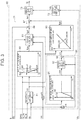
- FIG. 2 is a block diagram of a steering control device in the embodiment
- FIG. 3 is a block diagram of a limit value setting unit in the embodiment
- FIG. 4 is a flowchart showing a processing procedure of execution and stop of a partial release control by a release control unit in the embodiment
- FIG. 5 is a graph showing a temporal change in an angle limit component after correction in the embodiment.
- FIG. 6 is a graph showing a temporal change in the angle limit component after correction in a modification.
- an electric power steering device (EPS) 2 as a steering device that is controlled by a steering control device 1 includes a steering mechanism 5 that turns turning wheels 4 based on operation of a steering wheel 3 by a driver.
- the EPS 2 includes an EPS actuator 6 as an actuator that gives assist force for assisting steering operation, to the steering mechanism 5 .
- the steering mechanism 5 includes a steering shaft 11 to which a steering wheel 3 is fixed, a rack shaft 12 as a turning shaft that is coupled to the steering shaft 11 , a rack housing 13 as a housing into which a rack shaft 12 is inserted so as to be capable of reciprocating, and a rack-and-pinion mechanism 14 that transforms rotation of the steering shaft 11 into movement of the rack shaft 12 .
- the steering shaft 11 is constructed by coupling a column shaft 15 , an intermediate shaft 16 and a pinion shaft 17 in order from the position of the steering wheel 3 .
- the rack shaft 12 and the pinion shaft 17 are disposed at a predetermined crossing angle in the rack housing 13 .
- the rack-and-pinion mechanism 14 is constructed by engaging rack teeth 12 a formed on the rack shaft 12 and pinion teeth 17 a formed on the pinion shaft 17 .
- Tie rods 19 are rotatably coupled to both ends of the rack shaft 12 through rack ends 18 each of which is constituted by a ball joint provided at an end portion of the rack shaft 12 . Distal ends of the tie rods 19 are coupled to unillustrated knuckles to which the turning wheels 4 are attached.
- the rotation of the steering shaft 11 due to the steering operation is transformed into the axial movement of the rack shaft 12 by the rack-and-pinion mechanism 14 , and the axial movement is transmitted to the knuckles through the tie rods 19 , so that the turning angle of the turning wheels 4 , that is, the running direction of the vehicle is changed.
- a position of the rack shaft 12 where the rack end 18 abuts on the left end of the rack housing 13 is a position that allows a maximum rightward steering, and this position corresponds to a rack end position that is an end position on the right side. Further, a position of the rack shaft 12 where the rack end 18 abuts on the right end of the rack housing 13 is a position that allows a maximum leftward steering, and this position corresponds to a rack end position that is an end position on the left side.
- the EPS actuator 6 includes a motor 21 that is a drive source, and a speed reducer 22 such as a worm and wheel mechanism.
- the motor 21 is coupled to the column shaft 15 through the speed reducer 22 .
- the EPS actuator 6 reduces the speed of the rotation of the motor 21 with the speed reducer 22 , and then transmits the rotation of the motor 21 to the column shaft 15 . Thereby, the EPS actuator 6 gives motor torque to the steering mechanism 5 as the assist force.
- a three-phase brushless motor is employed as the motor 21 in the embodiment.
- the steering control device 1 is connected to the motor 21 , and controls action of the motor 21 .
- the steering control device 1 includes an unillustrated central processing unit (CPU) and an unillustrated memory, and the CPU executes programs stored in the memory in a predetermined computation cycle. Thereby, various controls are executed.
- the steering control device 1 is connected to a vehicle speed sensor 31 that detects a vehicle speed SPD of the vehicle, and a torque sensor 32 that detects a steering torque Th given to the steering shaft 11 due to the steering by the driver.
- the steering control device 1 is connected to a rotation sensor 33 that detects a rotation angle ⁇ m of the motor 21 as a relative angle in a range of 360°.
- the steering torque Th and the rotation angle ⁇ m are detected as positive values in the case of rightward steering, and are detected as negative values in the case of leftward steering.
- the steering control device 1 supplies drive electric power to the motor 21 based on signals that are input from the sensors and that indicate state quantities, and thereby controls the action of the EPS actuator 6 , that is, the assist force that is given to the steering mechanism 5 for reciprocating the rack shaft 12 .
- the steering control device 1 includes a microcomputer 41 as a control circuit that outputs a motor control signal Sm, and a drive circuit 42 that supplies the drive electric power to the motor 21 based on the motor control signal Sm.
- a drive circuit 42 in the embodiment, a well-known PWM inverter including a plurality of switching elements such as FETs is employed.
- the motor control signal Sm that is output by the microcomputer 41 specifies an on-state or off-state of each switching element.
- each switching element in response to the motor control signal Sm, each switching element is turned on or off, and a pattern of energization to motor coils for the respective phases is switched, so that direct-current electric power of an in-vehicle electric source 43 is transformed into three-phase drive electric power and the three-phase drive electric power is output to the motor 21 .
- Control blocks described below are realized by computer programs that are executed by the microcomputer 41 .
- the state quantities are detected in a predetermined sampling cycle, and computation processes indicated by the control blocks described below are executed in a predetermined computation cycle.
- the microcomputer 41 receives the vehicle speed SPD, the steering torque Th, and the rotation angle ⁇ m of the motor 21 . Further, the microcomputer 41 receives current values Iu, Iv, Iw in the respective phases of the motor 21 , which are current values detected by current sensors 44 , and a source voltage Vb of the in-vehicle electric source 43 , which is a source voltage detected by a voltage sensor 45 .
- the current sensors 44 are provided on connecting wires 46 between the drive circuit 42 and the motor coils for the respective phases.
- the voltage sensor 45 is provided on a connecting wire 47 between the in-vehicle electric source 43 and the drive circuit 42 . In FIG.
- the current sensors 44 for the respective phases and the connecting wires 46 for the respective phases are illustrated as a single current sensor 44 and a single connecting wire 46 , respectively.
- the microcomputer 41 outputs the motor control signal Sm based on the state quantities.
- the microcomputer 41 includes a current command value computation unit 51 that computes current command values Id*, Iq*, a motor control signal generation unit 52 that outputs the motor control signal Sm based on the current command values Id*, Iq*, and an absolute steer angle detection unit 53 that detects an absolute steer angle ⁇ s.
- the current command value computation unit 51 receives the vehicle speed SPD, the steering torque Th, the rotation angle ⁇ m and the absolute steer angle ⁇ s.
- the current command value computation unit 51 computes current command values Id*, Iq* based on the state quantities.
- the current command values Id*, Iq* are target values of electric currents that should be supplied to the motor 21 , and respectively indicate a current command value on a d-axis and a current command value on a q-axis in a d/q coordinate system.
- the q-axis current command value Iq* indicates a target value of the motor torque that is output by the motor 21 .
- the d-axis current command value Id* is basically fixed at zero.
- the current command values Id*, Iq* are positive values in the case of assist of the rightward steering, and are negative values in the case of assist of the leftward steering.
- the motor control signal generation unit 52 receives the current command values Id*, Iq*, the current values Iu, Iv, Iw in the respective phases, and the rotation angle ⁇ m of the motor 21 .
- the motor control signal generation unit 52 generates the motor control signal Sm by executing a current feedback control in the d/q ⁇ ordinate system based on the state quantities.
- the motor control signal generation unit 52 computes a d-axis current value Id and a q-axis current value Iq that are actual current values of the motor 21 in the d/q ⁇ ordinate system, by mapping the current values Iu, Iv, Iw in the respective phases on the d/q ⁇ ordinate system based on the rotation angle ⁇ m. Then, the motor control signal generation unit 52 generates the motor control signal Sm, by performing the current feedback control such that the d-axis current value Id follows the d-axis current command value Id* and performing the current feedback control such that the q-axis current value Iq follows the q-axis current command value Iq*.
- the motor control signal generation unit 52 outputs the motor control signal Sm generated in this way, to the drive circuit 42 . Thereby, the drive electric power corresponding to the motor control signal Sm is supplied to the motor 21 , and the motor torque corresponding to the q-axis current command value Iq* is output from the motor 21 , so that the assist force is given to the steering mechanism 5 .
- the absolute steer angle detection unit 53 receives the rotation angle ⁇ m.
- the absolute steer angle detection unit 53 detects a motor absolute angle that is expressed as an absolute angle having a range beyond 360°, based on the rotation angle ⁇ m.
- the absolute steer angle detection unit 53 in the embodiment sets, as a starting point, the rotation angle ⁇ m when a start switch such as an ignition switch is turned on for the first time, for example, after replacement of the in-vehicle electric source 43 , adds up the rotation number of the motor 21 , and detects the motor absolute angle based on the rotation number and the rotation angle ⁇ m.
- the absolute steer angle detection unit 53 detects the absolute steer angle ⁇ s indicating the steering angle of the steering shaft 11 , by multiplying the motor absolute angle by a conversion factor based on the reduction ratio of the speed reducer 22 .
- the steering control device 1 in the embodiment monitors whether the motor 21 rotates, even while the start switch is in the off-state, and adds up the rotation number of the motor 21 at all times. Therefore, even when the start switch is turned on for the second time after the replacement of the in-vehicle electric source 43 , the starting point of the absolute steer angle ⁇ s is the same as the starting point set when the start switch is turned on for the first time.
- the absolute steer angle ⁇ s indicates a rotation angle of a rotation shaft that is capable of being converted into the turning angle of the turning wheel 4 .
- the motor absolute angle and the absolute steer angle ⁇ s are positive values in the case of a rightward rotation angle with respect to the starting point, and are negative values in the case of a leftward rotation angle with respect to the starting point.
- the current command value computation unit 51 includes an assist command value computation unit 61 that computes an assist command value Ias* that is a basic component of the q-axis current command value Iq*. Further, the current command value computation unit 51 includes a limit value setting unit 62 that sets a limit value Ig that is an upper limit of the absolute value of the q-axis current command value Iq*, and a guard processing unit 63 that limits the absolute value of the assist command value Ias* to a value that is equal to or smaller than the limit value Ig.
- the limit value setting unit 62 is connected to a memory 64 .
- the assist command value computation unit 61 receives the steering torque Th and the vehicle speed SPD.
- the assist command value computation unit 61 computes the assist command value Ias* based on the steering torque Th and the vehicle speed SPD. Specifically, the assist command value computation unit 61 computes the assist command value Ias* having a larger absolute value as the absolute value of the steering torque Th increases and the vehicle speed SPD decreases.
- the assist command value Ias* computed in this way is output to the guard processing unit 63 .
- the guard processing unit 63 receives the limit value Ig that is set in the limit value setting unit 62 as described later.
- the guard processing unit 63 outputs, as the q-axis current command value Iq*, the value of the assist command value Ias* with no change, to the motor control signal generation unit 52 .
- the guard processing unit 63 outputs, as the q-axis current command value Iq*, a value resulting from limiting the absolute value of the assist command value Ias* to the limit value Ig, to the motor control signal generation unit 52 .
- a rated current Ir corresponding to a rated torque previously set as the motor torque that can be output by the motor 21 , end position correspondence angles ⁇ s_le, ⁇ s_re, and the like are stored.
- the end position correspondence angle ⁇ s_le on the left side is the absolute steer angle ⁇ s corresponding to the rack end position on the left side
- the end position correspondence angle ⁇ s_re on the right side is the absolute steer angle ⁇ s corresponding to the rack end position on the right side.
- the end position correspondence angle ⁇ s_le, ⁇ s_re are set, for example, by a learning that is appropriately performed based on the steering by the driver.
- the limit value setting unit 62 receives the rotation angle ⁇ m, the absolute steer angle ⁇ s, the vehicle speed SPD, the steering torque Th, the source voltage Vb, the rated current Ir, and the end position correspondence angles ⁇ s_le, ⁇ s_re.
- the limit value setting unit 62 sets the limit value Ig based on the state quantities.
- the limit value setting unit 62 includes a steer angle limit value computation unit 71 that computes the steer angle limit value Ien based on the absolute steer angle ⁇ s, a voltage limit value computation unit 72 that computes a voltage limit value Ivb as another limit value based on the source voltage Vb, and a minimum value selection unit 73 that selects the smaller one of the steer angle limit value Ien and the voltage limit value Ivb.
- the steer angle limit value computation unit 71 receives the rotation angle ⁇ m, the absolute steer angle ⁇ s, the vehicle speed SPD, the steering torque Th, the rated current Ir, and the end position correspondence angles ⁇ s_le, ⁇ s_re.
- an end interval angle ⁇ indicating the distance of the absolute steer angle ⁇ s from the end position correspondence angle ⁇ s_le, ⁇ s_re is equal to or smaller than a predetermined angle ⁇ 1 as described later, based on the state quantities
- the steer angle limit value computation unit 71 computes the steer angle limit value Ien that decreases based on decrease in the end interval angle ⁇ .
- the steer angle limit value Ien computed in this way is output to the minimum value selection unit 73 .
- the voltage limit value computation unit 72 receives the source voltage Vb. When the absolute value of the source voltage Vb is equal to or smaller than a preset voltage threshold Vth, the voltage limit value computation unit 72 computes the voltage limit value Ivb that is smaller than a rated voltage for supplying the rated current Ir. Specifically, when the absolute value of the source voltage Vb is equal to or smaller than the voltage threshold Vth, the voltage limit value computation unit 72 computes the voltage limit value Ivb having a smaller absolute value based on the decrease in the absolute value of the source voltage Vb. The voltage limit value Ivb computed in this way is output to the minimum value selection unit 73 .
- the minimum value selection unit 73 selects, as the limit value Ig, the smaller one of the steer angle limit value Ien and voltage limit value Ivb that are input, and outputs the smaller one to the guard processing unit 63 .
- the steer angle limit value Ien is output to the guard processing unit 63 as the limit value Ig
- the absolute value of the q-axis current command value Iq* is limited to the steer angle limit value Ien.
- the end-abutting relaxation control relaxes impact of end abutting. That is, the current command value computation unit 51 in the embodiment corrects the q-axis current command value Iq* in a manner in which the absolute value of the q-axis current command value Iq* is limited to a value that is equal to or smaller than the limit value Ig.
- the correction amount of the q-axis current command value Iq* is an excess of the assist command value Ias* relative to the limit value Ig, that is, an excess relative to the steer angle limit value Ien.
- the absolute value of the q-axis current command value Iq* is limited to the voltage limit value Ivb.
- a source protection control is executed.
- the absolute value of the q-axis current command value Iq* decreases based on the decrease in the absolute value of the source voltage Vb.
- the steer angle limit value computation unit 71 includes an end interval angle computation unit 81 that computes the end interval angle ⁇ , an angle limit component computation unit 82 that computes an angle limit component Iga that is a current limit amount decided depending on the end interval angle ⁇ , and a release control unit 83 that corrects the angle limit component Iga.
- the steer angle limit value computation unit 71 includes an excess angular velocity computation unit 84 that computes an excess angular velocity ⁇ o that is an excess of a steering velocity cos relative to an upper limit angular velocity ⁇ lim, and a velocity limit component computation unit 85 that computes a velocity limit component Igs that is a current limit amount decided depending on the excess angular velocity ⁇ o.
- the end interval angle computation unit 81 receives the absolute steer angle ⁇ s and the end position correspondence angles ⁇ s_le, ⁇ s_re.
- the end interval angle computation unit 81 computes the difference between the absolute steer angle ⁇ s in the last computation cycle and the end position correspondence angle ⁇ s_le on the left side and the difference between the absolute steer angle ⁇ s in the last computation cycle and the end position correspondence angle ⁇ s_re on the right side. Then, the end interval angle computation unit 81 outputs a difference that is of the computed differences and that is smaller in absolute value, to the angle limit component computation unit 82 and the excess angular velocity computation unit 84 , as the end interval angle ⁇ .
- the angle limit component computation unit 82 receives the end interval angle ⁇ and the vehicle speed SPD.
- the angle limit component computation unit 82 includes a map deciding a relation of the end interval angle ⁇ , the vehicle speed SPD and the angle limit component Iga, and computes the angle limit component Iga corresponding to the end interval angle ⁇ and the vehicle speed SPD, by referring to the map.
- the angle limit component Iga is set so as to decrease in proportion to increase in the end interval angle ⁇ from zero and to become zero when the end interval angle ⁇ becomes larger than the predetermined angle ⁇ 1.
- a region where the end interval angle ⁇ is negative is also set.
- the angle limit component Iga increases in proportion to decrease in the end interval angle ⁇ when the end interval angle ⁇ is smaller than zero, and is constant after the angle limit component Iga becomes the same value as the rated current Ir.
- the rotation of the motor 21 due to elastic deformation of the EPS 2 by further performing an additional steering in the state where the rack end 18 abuts on the rack housing 13 is considered.
- the predetermined angle ⁇ 1 is set to a small angle indicating ranges of vicinities of the end position correspondence angles ⁇ s_le, ⁇ s_re. That is, the angle limit component Iga is set so as to be smaller as the absolute steer angle ⁇ s is closer to a steering neutral side with respect to the end position correspondence angles ⁇ s_le, ⁇ s_re, and to be zero when the absolute steer angle ⁇ s is on the steering neutral position side beyond the vicinities of the end position correspondence angles ⁇ s_le, ⁇ s_re.
- the angle limit component Iga is set so as to decrease based on increase in the vehicle speed SPD, in a region in which the end interval angle M is equal to or smaller than the predetermined angle ⁇ 1. Specifically, in a region in which the vehicle speed SPD is in a low speed range, the angle limit component Iga is set so as to be larger than zero, and in a region in which the vehicle speed SPD is in a middle or high speed range, the angle limit component Iga is set so as to be zero.
- the angle limit component Iga computed in this way is output to the release control unit 83 .
- the release control unit 83 corrects the angle limit component Iga described later, and outputs an angle limit component Iga′ after the correction, to a subtracter 86 .
- the excess angular velocity computation unit 84 receives the end interval angle ⁇ and the steering velocity cos that is obtained by differentiating the absolute steer angle ⁇ s.
- the excess angular velocity computation unit 84 computes the excess angular velocity ⁇ o based on the state quantities.
- the excess angular velocity computation unit 84 includes an upper limit angular velocity computation unit 91 that computes the upper limit angular velocity ⁇ lim.
- the upper limit angular velocity computation unit 91 receives the end interval angle ⁇ .
- the upper limit angular velocity computation unit 91 includes a map deciding a relation of the end interval angle ⁇ and the upper limit angular velocity ⁇ lim, and computes the upper limit angular velocity ⁇ lim corresponding to the end interval angle ⁇ , by referring to the map.
- the upper limit angular velocity ⁇ lim is set such that the upper limit angular velocity ⁇ lim is lowest when the end interval angle ⁇ is larger than zero but is close to zero and the upper limit angular velocity ⁇ lim increases in proportion to increase in the end interval angle ⁇ . Further, the upper limit angular velocity ⁇ lim is set so as to be kept at a value that is previously set as the maximum angular velocity at which the motor 21 can rotate, when the end interval angle ⁇ is larger than a predetermined angle ⁇ 2.
- the predetermined angle ⁇ 2 is set to an angle that is larger than the above predetermined angle ⁇ 1.
- the excess angular velocity computation unit 84 When the absolute value of the steering velocity cos is higher than the upper limit angular velocity ⁇ lim corresponding to the end interval angle ⁇ , the excess angular velocity computation unit 84 outputs the excess of the steering velocity ⁇ s relative to the upper limit angular velocity ⁇ lim, to the velocity limit component computation unit 85 , as the excess angular velocity ⁇ o.
- the excess angular velocity computation unit 84 outputs the excess angular velocity ⁇ o indicating zero, to the velocity limit component computation unit 85 .
- the excess angular velocity computation unit 84 includes a minimum value selection unit 92 that receives the upper limit angular velocity ⁇ lim and the steering velocity ⁇ s.
- the minimum value selection unit 92 selects the smaller one of the upper limit angular velocity ⁇ lim and the absolute value of the steering velocity ⁇ s, and outputs the smaller one to a subtracter 93 .
- the excess angular velocity computation unit 84 computes the excess angular velocity ⁇ o by subtracting the output value of the minimum value selection unit 92 from the absolute value of the steering velocity ⁇ s.
- the steering velocity ⁇ s is subtracted from the steering velocity cos by the subtracter 93 , so that the excess angular velocity ⁇ o becomes zero.
- the upper limit angular velocity ⁇ lim is subtracted from the absolute value of the steering velocity ⁇ s by the subtracter 93 , so that the excess of the steering velocity ⁇ s relative to the upper limit angular velocity ⁇ lim is the excess angular velocity ⁇ o.
- the velocity limit component computation unit 85 receives the excess angular velocity ⁇ o and the vehicle speed SPD.
- the velocity limit component computation unit 85 includes a map deciding a relation of the excess angular velocity ⁇ o, the vehicle speed SPD and the velocity limit component Igs, and computes the velocity limit component Igs corresponding to the excess angular velocity ⁇ o and the vehicle speed SPD, by referring to the map.
- the velocity limit component Igs is set such that the velocity limit component Igs is smallest when the excess angular velocity ⁇ o is zero and the velocity limit component Igs increases in proportion to increase in the excess angular velocity ⁇ o. Further, in the map, the velocity limit component Igs is set so as to decrease based on increase in the vehicle speed SPD. In the map, the absolute value of the velocity limit component Igs is set so as to be smaller than the absolute value of the angle limit component Iga. The velocity limit component Igs computed in this way is output to a subtracter 87 .
- the rated current Ir is input to the subtracter 86 that receives the angle limit component Iga′ after the above correction.
- the steer angle limit value computation unit 71 outputs a value resulting from subtracting the angle limit component Iga′ after the correction from the rated current Ir with the subtracter 86 , to the subtracter 87 that receives the velocity limit component Igs.
- the steer angle limit value computation unit 71 outputs a value resulting from subtracting the velocity limit component Igs from the output value of the subtracter 86 with the subtracter 87 , that is, a value resulting from subtracting the angle limit component Iga′ after the correction and the velocity limit component Igs from the rated current Ir, to the minimum value selection unit 73 , as the steer angle limit value Ien.
- the release control unit 83 When movement of the rack shaft 12 is restricted at a virtual rack end position on a steering neutral position side of an actual rack end position due to the execution of the end-abutting relaxation control, the small-slewing performance of the vehicle can decrease. In view of this point, when the driver intends to perform slewing travel, the release control unit 83 allows the rack shaft 12 to move to the actual rack end position, by executing a partial release control to reduce the correction amount of the q-axis current command value Iq* in the execution of the end-abutting relaxation control, that is, to partially release the limitation of the q-axis current command value Iq*.
- the guard processing unit 63 limits the absolute value of the q-axis current command value Iq* to a value that is equal to or smaller than the limit value Ig. Therefore, as the steer angle limit value Ien as the limit value Ig is larger, the correction amount of the q-axis current command value Iq* is smaller.
- the steer angle limit value Ien is computed by subtracting the angle limit component Iga′ after the correction and the velocity limit component Igs from the rated current Ir. Therefore, as the angle limit component Iga′ is smaller, the steer angle limit value Ien is larger and the correction amount of the q-axis current command value Iq* is smaller.
- the release control unit 83 in the embodiment performs the correction such that the input angle limit component Iga decreases, and thereby executes the partial release control to reduce the correction amount of the q-axis current command value Iq* in the execution of the end-abutting relaxation control.
- the release control unit 83 receives the vehicle speed SPD, the steering torque Th, and a motor angular velocity ⁇ m obtained by differentiating the rotation angle ⁇ m. Based on the state quantities, the release control unit 83 performs a slewing intention determination of whether the driver intends to perform the slewing travel of the vehicle by performing the additional steering or keeping the steering state during the execution of the end-abutting relaxation control. Then, when it is determined that the driver intends to perform the slewing travel, the release control unit 83 corrects the angle limit component Iga such that the angle limit component Iga decreases, and outputs the angle limit component Iga′ after the correction, to the subtracter 86 .
- the release control unit 83 performs computation during the execution of the partial release control, such that the angle limit component Iga′ after the correction is gradually reduced to a release target value Itrg. Specifically, the release control unit 83 linearly reduces the angle limit component Iga such that the angle limit component Iga′ after the correction becomes the release target value Itrg, with time lapse from the start time of the partial release control.
- the release target value Itrg is set such that, when the angle limit component Iga′ after the correction becomes the release target value Itrg, a predetermined assist force allowing the rack shaft 12 to move to the rack end position is given from the motor 21 , for example, in the case where the vehicle travels on a normal road surface at low speed.
- the absolute value of the steer angle limit value Ien obtained by subtracting the release target value Itrg and the velocity limit component Igs from the rated current Ir has such a magnitude that the predetermined assist force is output from the motor 21 by the supply of the electric current to the motor 21 .
- the release target value Itrg is a current value based on the rated current Ir, and is set to 50% of the rated current Ir, for example.
- the release control unit 83 stops the partial release control, when the angle limit component Iga before the correction based on the end interval angle ⁇ becomes smaller than the release target value Itrg, for example, by driver's return steering. That is, the release control unit 83 outputs the input angle limit component Iga, with no change, as the angle limit component Iga′ after the correction, and does not change the correction amount in the execution of the end-abutting relaxation control.
- the release control unit 83 When it is determined that the driver does not intend to perform the slewing travel during the execution of the end-abutting relaxation control, the release control unit 83 outputs the input angle limit component Iga, with no change, as the angle limit component Iga′ after the correction. That is, when it is determined that the driver does not intend to the slewing travel, the release control unit 83 does not execute the partial release control.
- the release control unit 83 determines that the driver intends to perform the slewing travel of the vehicle during the execution of the end-abutting relaxation control, when a condition for the slewing intention determination that is constituted by (a) to (e) described below is continuously satisfied for a predetermined time.
- the predetermined time is set to an appropriate time allowing the determination that the driver is performing the additional steering or is keeping the steering state.
- the vehicle speed SPD is in a predetermined vehicle speed range.
- the release control unit 83 computes the angular velocity change amount ⁇ m that is the change amount of the motor angular velocity ⁇ m, based on the input motor angular velocity ⁇ m, and uses the computed angular velocity change amount ⁇ m subjected to a low-pass filter process.
- the current threshold Ith is a current value based on the rated current Ir, and is set to the same value as the above release target value Itrg, in the embodiment.
- the steering torque threshold Tth is a steering torque necessary to keep the steering wheel 3 for the slewing travel of the vehicle in the state where the rack end 18 abuts on the rack housing 13 , and is set to an appropriate value that is larger than zero.
- the predetermined vehicle speed range indicates a vehicle speed range of equal to or higher than a lower limit vehicle speed Slo and lower than an upper limit vehicle speed Sup.
- the lower limit vehicle speed Slo indicates that the vehicle is not in a stop state
- the upper limit vehicle speed Sup indicates that the vehicle is traveling at low speed.
- the lower limit vehicle speed Slo is set to a value that is slightly higher than zero
- the upper limit vehicle speed Sup is set to an appropriate value that is higher than the lower limit vehicle speed Slo.
- the angular velocity threshold wth is an angular velocity indicating the stop of the motor 21 , and is set to a value that is slightly higher than zero.
- the angular velocity change amount threshold ⁇ th is an angular velocity change amount indicating that the motor 21 roughly neither accelerates nor decelerates, and is set to a value that is slightly larger than zero.
- the release control unit 83 acquires various state quantities (step 101 ), and then determines whether a flag indicating that the partial release control is being executed is set (step 102 ).
- the release control unit 83 determines whether the vehicle speed SPD is equal to or higher than the lower limit vehicle speed Slo and is lower than the upper limit vehicle speed Sup (step 103 ). In the case where the vehicle speed SPD is equal to or higher than the lower limit vehicle speed Slo and is lower than the upper limit vehicle speed Sup and is in the predetermined vehicle speed range (step 103 : YES), the release control unit 83 determines whether the angle limit component Iga is larger than the current threshold Ith (step 104 ).
- the release control unit 83 determines whether the absolute value of the steering torque Th is equal to or larger than the steering torque threshold Tth (step 105 ). In the case where the absolute value of the steering torque Th is equal to or larger than the steering torque threshold Tth (step 105 : YES), the release control unit 83 determines whether the absolute value of the motor angular velocity wm is equal to or smaller than the angular velocity threshold wth (step 106 ).
- the release control unit 83 determines whether the angular velocity change amount ⁇ m is smaller than the angular velocity change amount threshold ⁇ th (step 107 ). In the case where the angular velocity change amount ⁇ m is smaller than the angular velocity change amount threshold ⁇ th (step 107 ; YES), the release control unit 83 transitions to step 108 .
- step 108 the release control unit 83 increments a count value Cn of a counter indicating a time that has lapsed since the determination in steps 103 to 107 , that is, the satisfaction of the conditions (a) to (e). Subsequently, the release control unit 83 determines whether the count value Cn is larger than a predetermined count value Cth corresponding to the predetermined time (step 109 ). In the case where the count value Cn is larger than the predetermined count value Cth (step 109 : YES), the release control unit 83 starts the partial release control (step 110 ), sets the flag (step 111 ), and clears the count value Cn of the counter (step 112 ).
- step 109 the release control unit 83 does not execute the processes after that. Further, in the case where one of steps 103 to 107 is not satisfied (steps 103 to 107 : NO), the release control unit 83 does not execute the processes in steps 108 to 111 , and transitions to step 112 to clear the count value Cn.
- the release control unit 83 determines whether the angle limit component Iga computed based on the end interval angle ⁇ is smaller than the release target value Itrg, that is, the current threshold Ith (step 113 ). In the case where the angle limit component Iga is smaller than the release target value Itrg (step 113 : YES), the release control unit 83 stops the partial release control (step 114 ), and resets the flag (step 115 ). In the case where the angle limit component Iga is equal to or larger than the release target value Itrg (step 113 : NO), the release control unit 83 does not execute the processes after that.
- the release control unit 83 When it is determined that the driver intends to perform the slewing travel of the vehicle during the execution of the end-abutting relaxation control, the release control unit 83 performs the partial release control to reduce the correction amount of the q-axis current command value Iq* in the execution of the end-abutting relaxation control. Thereby, the limitation of the q-axis current command value Iq* by the execution of the end-abutting relaxation control is partially released, and the q-axis current command value Iq* increases.
- the partial release control is executed and the q-axis current command value Iq* increases because of the driver's intention to perform the slewing travel. Therefore, it is possible to move the rack shaft 12 to the actual rack end position. As a result, it is possible to restrain the decrease in the small-slewing performance of the vehicle.
- the current command value computation unit 51 includes the steer angle limit value computation unit 71 that computes the steer angle limit value Ien that decreases based on the decrease in the end interval angle ⁇ when the end interval angle ⁇ is equal to or smaller than the predetermined angle ⁇ 1, and the limit value setting unit 62 that sets the limit value Ig to the value that is equal to or smaller than the steer angle limit value Ien.
- the current command value computation unit 51 executes the end-abutting relaxation control by limiting the absolute value of the q-axis current command value Iq* to the steer angle limit value Ien.
- the steer angle limit value computation unit 71 computes, as the steer angle limit value Ien, the value resulting from subtracting the angle limit component Iga′ and the velocity limit component Igs from the rated current Ir.
- the release control unit 83 reduces the angle limit component Iga during the execution of the partial release control. Accordingly, with the embodiment, in the configuration of executing the end-abutting relaxation control in the manner in which the q-axis current command value Iq* is limited to the value that is equal to or smaller than the steer angle limit value Ien, it is possible to easily execute the partial release control to reduce the correction amount of the q-axis current command value Iq* by reducing the angle limit component Iga that is a base of the steer angle limit value Ien.
- the release control unit 83 determines that the driver intends to perform the slewing travel of the vehicle during the execution of the end-abutting relaxation control, when the conditions (a) to (e) are continuously satisfied for the predetermined time. Therefore, it is possible to more exactly determine the situation in which the driver intends to perform the slewing travel while performing the additional steering or keeping the steering state in the state where the movement of the rack shaft 12 is restricted at the virtual rack end position due to the execution of the end-abutting relaxation control.
- the release control unit 83 linearly reduces the angle limit component Iga, with time lapse from the start time of the partial release control. Therefore, it is possible to suitably increase the steer angle limit value Ien, and furthermore it is possible to suitably increase the q-axis current command value Iq*. Thereby, for example, even when the rack shaft 12 is moved by the execution of the partial release control and the end abutting occurs, it is possible to restrain a great load from being given to the EPS 2 at the time of the end abutting.
- the release control unit 83 stops the partial release control, when the return steering is performed after the execution of the partial release control and the angle limit component Iga before the reduction by the execution of the partial release control, that is, the angle limit component Iga before the correction becomes smaller than the release target value Itrg. Therefore, for example, unlike the case of stopping the partial release control in a state where the angle limit component Iga before the reduction by the execution of the partial release control is equal to or larger than the release target value Itrg, it is possible to prevent the steer angle limit value Ien, that is, the q-axis current command value Iq* from changing suddenly, and to restrain a steering feeling from being worsened.
- the embodiment can be carried out while being modified as follows.
- the embodiment and the following modifications can be carried out while being mutually combined as long as there is no technical inconsistency.
- the angle limit component Iga′ after the correction is linearly reduced with time lapse from a start time of the partial release control.
- the manner in which the angle limit component Iga is reduced can be appropriately modified.
- the release target value Itrg is set to the same value as the current threshold Ith.
- the release target value Itrg may be set to a value that is larger than the current threshold Ith, for example.
- the partial release control is stopped when the angle limit component Iga before the reduction by the execution of the partial release control becomes smaller than the release target value Itrg after the execution of the partial release control.
- the partial release control may be stopped, for example, when one of the conditions (a) to (e) is not satisfied.
- the condition for the determination can be appropriately modified. For example, it may be determined that the driver intends to perform the slewing travel of the vehicle, when the conditions (a) to (e) are satisfied, regardless of whether the satisfaction continues for the predetermined time.
- the condition (d) and (e) it is not necessary to determine whether the condition is satisfied, and furthermore, for example, it is allowable to determine whether the yaw rate of the vehicle is equal to or higher than a yaw rate threshold indicating the slewing state, instead of the condition (c). Moreover, in the conditions (d) and (e), it is allowable to use the steering velocity cos instead of the motor angular velocity ⁇ m.
- the steering control device 1 when it is determined that the driver intends to perform the slewing travel of the vehicle during the execution of the end-abutting relaxation control, the steering control device 1 reduces the correction amount of the q-axis current command value Iq* by correcting the angle limit component Iga such that the angle limit component Iga decreases.
- the manner of the partial release control can be appropriately modified. For example, it is allowable to reduce the correction amount of the q-axis current command value Iq* by correcting the steer angle limit value Ien such that the steer angle limit value Ien increases.
- the steering control device 1 by monitoring whether the motor 21 rotates even while the ignition switch is in the off-state, the steering control device 1 adds up the rotation number of the motor 21 from the starting point at all times, and computes the motor absolute angle.
- the steering control device 1 may be provided with a steering sensor that detects the steering angle as an absolute angle. The steering control device 1 may add up the rotation number of the motor 21 from the starting point, based on the steering angle detected by the steering sensor and the reduction ratio of the speed reducer 22 , and may compute the motor absolute angle.
- the steering control device 1 executes the end-abutting relaxation control, by limiting the assist command value Ias* to the steer angle limit value Ien.
- the steering control device 1 may execute the end-abutting relaxation control, by adding, to the assist command value Ias*, a steering reaction component that is larger as the rack shaft 12 approaches the rack end position, that is, a component that has a sign opposite to the sign of the assist command value Ias*.
- a steering reaction component that is larger as the rack shaft 12 approaches the rack end position, that is, a component that has a sign opposite to the sign of the assist command value Ias*.
- the steering control device 1 performs the guard process to the assist command value Ias*.
- the steering control device 1 may perform the guard process for a value resulting from correcting the assist command value Ias* with a compensation amount based on a torque differential value resulting from differentiating the steering torque Th.
- the limit value setting unit 62 includes the voltage limit value computation unit 72 that computes the voltage limit value Ivb based on the source voltage Vb.
- the limit value setting unit 62 may include another computation unit that computes another limit value based on another state quantity, in addition to or instead of the voltage limit value computation unit 72 .
- the limit value setting unit 62 may be configured to set the steer angle limit value Ien itself as the limit value Ig, without including the voltage limit value computation unit 72 .
- the steer angle limit value Ien may be a value resulting from subtracting only the angle limit component Iga from the rated current Ir.
- the steering control device 1 controls the EPS 2 , which is a type of steering device in which the EPS actuator 6 gives the motor torque to the column shaft 15 .
- the steering control device 1 may control a type of steering device that gives the motor torque to the rack shaft 12 through a ball screw nut.
- the steering control device 1 may control a steer-by-wire steering device in which dynamic power is not transmitted between a steering unit that is operated by the driver and a turning unit that turns turning wheels, and may execute the end-abutting relaxation control in the embodiment, for a torque command value or q-axis current command value of a motor of a turning actuator provided in the turning unit.
Landscapes
- Engineering & Computer Science (AREA)
- Chemical & Material Sciences (AREA)
- Combustion & Propulsion (AREA)
- Transportation (AREA)
- Mechanical Engineering (AREA)
- Steering Control In Accordance With Driving Conditions (AREA)
- Power Steering Mechanism (AREA)
Applications Claiming Priority (3)
| Application Number | Priority Date | Filing Date | Title |
|---|---|---|---|
| JPJP2019-164432 | 2019-09-10 | ||
| JP2019-164432 | 2019-09-10 | ||
| JP2019164432A JP7404004B2 (ja) | 2019-09-10 | 2019-09-10 | 操舵制御装置 |
Publications (2)
| Publication Number | Publication Date |
|---|---|
| US20210070352A1 US20210070352A1 (en) | 2021-03-11 |
| US11167790B2 true US11167790B2 (en) | 2021-11-09 |
Family
ID=72340285
Family Applications (1)
| Application Number | Title | Priority Date | Filing Date |
|---|---|---|---|
| US17/013,957 Active US11167790B2 (en) | 2019-09-10 | 2020-09-08 | Steering control device |
Country Status (4)
| Country | Link |
|---|---|
| US (1) | US11167790B2 (ja) |
| EP (1) | EP3792152B1 (ja) |
| JP (1) | JP7404004B2 (ja) |
| CN (1) | CN112550435B (ja) |
Citations (7)
| Publication number | Priority date | Publication date | Assignee | Title |
|---|---|---|---|---|
| EP0325148A2 (en) | 1988-01-20 | 1989-07-26 | Mitsubishi Denki Kabushiki Kaisha | Power steering system of motor drive type |
| WO2002081288A2 (de) | 2001-04-09 | 2002-10-17 | Mercedes Benz Lenkungen Gmbh | Motorgetriebene servolenkungseinheit |
| DE102005038390A1 (de) | 2004-12-07 | 2006-06-14 | Volkswagen Ag | Lenkung eines Fahrzeugs |
| DE102012004503A1 (de) | 2012-03-05 | 2013-09-05 | Audi Ag | Verfahren zum Betreiben eines elektronischen Servolenksystems |
| JP2015020506A (ja) | 2013-07-17 | 2015-02-02 | 株式会社ジェイテクト | ステアリング装置 |
| JP5962881B1 (ja) | 2014-10-01 | 2016-08-03 | 日本精工株式会社 | 電動パワーステアリング装置 |
| US20180079447A1 (en) | 2016-09-16 | 2018-03-22 | Jtekt Corporation | Steering Device |
Family Cites Families (7)
| Publication number | Priority date | Publication date | Assignee | Title |
|---|---|---|---|---|
| JP2007153158A (ja) | 2005-12-06 | 2007-06-21 | Toyota Motor Corp | 車両の操舵装置 |
| JP2008137486A (ja) * | 2006-12-01 | 2008-06-19 | Jtekt Corp | 電動パワーステアリング装置 |
| JP2008213643A (ja) * | 2007-03-02 | 2008-09-18 | Nsk Ltd | 電動パワーステアリング装置 |
| JP6380014B2 (ja) * | 2014-11-04 | 2018-08-29 | 株式会社ジェイテクト | 電動パワーステアリング装置 |
| JP2017210216A (ja) | 2016-05-27 | 2017-11-30 | 日本精工株式会社 | 電動パワーステアリング装置の制御装置 |
| JP6760799B2 (ja) * | 2016-08-26 | 2020-09-23 | 株式会社ジェイテクト | 操舵制御装置 |
| JP6965697B2 (ja) * | 2017-11-09 | 2021-11-10 | 株式会社ジェイテクト | 操舵制御装置 |
-
2019
- 2019-09-10 JP JP2019164432A patent/JP7404004B2/ja active Active
-
2020
- 2020-09-02 EP EP20194101.0A patent/EP3792152B1/en active Active
- 2020-09-08 CN CN202010935756.0A patent/CN112550435B/zh active Active
- 2020-09-08 US US17/013,957 patent/US11167790B2/en active Active
Patent Citations (10)
| Publication number | Priority date | Publication date | Assignee | Title |
|---|---|---|---|---|
| EP0325148A2 (en) | 1988-01-20 | 1989-07-26 | Mitsubishi Denki Kabushiki Kaisha | Power steering system of motor drive type |
| WO2002081288A2 (de) | 2001-04-09 | 2002-10-17 | Mercedes Benz Lenkungen Gmbh | Motorgetriebene servolenkungseinheit |
| US20040098180A1 (en) | 2001-04-09 | 2004-05-20 | Klaus Von Hammel | Motor-driven power steering unit |
| DE102005038390A1 (de) | 2004-12-07 | 2006-06-14 | Volkswagen Ag | Lenkung eines Fahrzeugs |
| DE102012004503A1 (de) | 2012-03-05 | 2013-09-05 | Audi Ag | Verfahren zum Betreiben eines elektronischen Servolenksystems |
| JP2015020506A (ja) | 2013-07-17 | 2015-02-02 | 株式会社ジェイテクト | ステアリング装置 |
| JP5962881B1 (ja) | 2014-10-01 | 2016-08-03 | 日本精工株式会社 | 電動パワーステアリング装置 |
| EP3170720A1 (en) | 2014-10-01 | 2017-05-24 | NSK Ltd. | Electric power steering device |
| US20180194389A1 (en) | 2014-10-01 | 2018-07-12 | Nsk Ltd. | Electric power steering apparatus |
| US20180079447A1 (en) | 2016-09-16 | 2018-03-22 | Jtekt Corporation | Steering Device |
Non-Patent Citations (1)
| Title |
|---|
| Feb. 2, 2021 Search Report issued in European Patent Application No. 20194101.0. |
Also Published As
| Publication number | Publication date |
|---|---|
| CN112550435A (zh) | 2021-03-26 |
| US20210070352A1 (en) | 2021-03-11 |
| CN112550435B (zh) | 2024-11-26 |
| EP3792152B1 (en) | 2025-10-15 |
| JP7404004B2 (ja) | 2023-12-25 |
| EP3792152A1 (en) | 2021-03-17 |
| JP2021041785A (ja) | 2021-03-18 |
Similar Documents
| Publication | Publication Date | Title |
|---|---|---|
| US8272474B2 (en) | Electric power steering system | |
| US11926375B2 (en) | Steering control device | |
| JP7122160B2 (ja) | 操舵制御装置 | |
| US11679802B2 (en) | Steering control device | |
| US11685429B2 (en) | Steering control device | |
| US11919581B2 (en) | Steering control device | |
| US11897555B2 (en) | Steering control device | |
| US11685428B2 (en) | Steering control device | |
| US11975772B2 (en) | Steering control device | |
| US11167790B2 (en) | Steering control device | |
| JP7772100B2 (ja) | 操舵制御装置及び操舵制御方法 |
Legal Events
| Date | Code | Title | Description |
|---|---|---|---|
| FEPP | Fee payment procedure |
Free format text: ENTITY STATUS SET TO UNDISCOUNTED (ORIGINAL EVENT CODE: BIG.); ENTITY STATUS OF PATENT OWNER: LARGE ENTITY |
|
| AS | Assignment |
Owner name: JTEKT CORPORATION, JAPAN Free format text: ASSIGNMENT OF ASSIGNORS INTEREST;ASSIGNORS:KATAOKA, NOBUAKI;TOKO, TAKAHIRO;YAMAGUCHI, TAKAFUMI;AND OTHERS;SIGNING DATES FROM 20201101 TO 20201222;REEL/FRAME:055183/0657 |
|
| STPP | Information on status: patent application and granting procedure in general |
Free format text: NOTICE OF ALLOWANCE MAILED -- APPLICATION RECEIVED IN OFFICE OF PUBLICATIONS |
|
| STPP | Information on status: patent application and granting procedure in general |
Free format text: PUBLICATIONS -- ISSUE FEE PAYMENT VERIFIED |
|
| STCF | Information on status: patent grant |
Free format text: PATENTED CASE |
|
| CC | Certificate of correction | ||
| MAFP | Maintenance fee payment |
Free format text: PAYMENT OF MAINTENANCE FEE, 4TH YEAR, LARGE ENTITY (ORIGINAL EVENT CODE: M1551); ENTITY STATUS OF PATENT OWNER: LARGE ENTITY Year of fee payment: 4 |