US1120597A - Bottle-filling apparatus. - Google Patents
Bottle-filling apparatus. Download PDFInfo
- Publication number
- US1120597A US1120597A US68134012A US1912681340A US1120597A US 1120597 A US1120597 A US 1120597A US 68134012 A US68134012 A US 68134012A US 1912681340 A US1912681340 A US 1912681340A US 1120597 A US1120597 A US 1120597A
- Authority
- US
- United States
- Prior art keywords
- bottle
- vent tube
- valve
- filling
- tube
- Prior art date
- Legal status (The legal status is an assumption and is not a legal conclusion. Google has not performed a legal analysis and makes no representation as to the accuracy of the status listed.)
- Expired - Lifetime
Links
- 230000001276 controlling effect Effects 0.000 description 18
- 238000013022 venting Methods 0.000 description 18
- 239000007788 liquid Substances 0.000 description 10
- 230000008878 coupling Effects 0.000 description 7
- 238000010168 coupling process Methods 0.000 description 7
- 238000005859 coupling reaction Methods 0.000 description 7
- 238000013459 approach Methods 0.000 description 5
- 210000002445 nipple Anatomy 0.000 description 5
- XLYOFNOQVPJJNP-UHFFFAOYSA-N water Substances O XLYOFNOQVPJJNP-UHFFFAOYSA-N 0.000 description 4
- 238000012856 packing Methods 0.000 description 3
- 230000001105 regulatory effect Effects 0.000 description 3
- 238000007789 sealing Methods 0.000 description 3
- 241001446467 Mama Species 0.000 description 1
- 240000007182 Ochroma pyramidale Species 0.000 description 1
- 229940000425 combination drug Drugs 0.000 description 1
- 230000002222 downregulating effect Effects 0.000 description 1
- VBCVPMMZEGZULK-NRFANRHFSA-N indoxacarb Chemical compound C([C@@]1(OC2)C(=O)OC)C3=CC(Cl)=CC=C3C1=NN2C(=O)N(C(=O)OC)C1=CC=C(OC(F)(F)F)C=C1 VBCVPMMZEGZULK-NRFANRHFSA-N 0.000 description 1
- 239000000463 material Substances 0.000 description 1
- 235000019988 mead Nutrition 0.000 description 1
- 239000006188 syrup Substances 0.000 description 1
- 235000020357 syrup Nutrition 0.000 description 1
- 239000002699 waste material Substances 0.000 description 1
- 239000003643 water by type Substances 0.000 description 1
Images


Classifications
-
- B—PERFORMING OPERATIONS; TRANSPORTING
- B67—OPENING, CLOSING OR CLEANING BOTTLES, JARS OR SIMILAR CONTAINERS; LIQUID HANDLING
- B67C—CLEANING, FILLING WITH LIQUIDS OR SEMILIQUIDS, OR EMPTYING, OF BOTTLES, JARS, CANS, CASKS, BARRELS, OR SIMILAR CONTAINERS, NOT OTHERWISE PROVIDED FOR; FUNNELS
- B67C7/00—Concurrent cleaning, filling, and closing of bottles; Processes or devices for at least two of these operations
Definitions
- I provide improved means for adjusting the position of the vent tube in relation to the bottle for filling to different heights and improved means for cutting off the venting and regulating the size of the venting orifice to meet different conditions, as for instance. of the character of material being supplied to the bottle and the gaseous pressure.
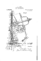
- Figure 1 s a vertical sectional view through a filling mead of a bottling machine and associated parts, embodying my invention, and With i vent tube raised above the bottle when upper end is in the filling chamber.
- Fig. s a vievv similar to Fig. 1 of some of the its there shown but with the vent tube in lowest position.
- Fig. 3 is a view on a larger scale, of the vent tube, its carrier leeve, the stop sleeve, needle valve and associate features, this view being a section taken a quarter turn from that of Figs. 1 and '2.
- 3 is a detail vievv.
- Fig. l is a sectional plan view substantially on the line l--t of Fig. 3.
- Fig. 5 18 a cross section of Fig. 3 on the line 5-5.
- Fig. 6 is a plan view of an abutment ring.
- 1 represents the filling head having lower end a rubber gasket 2, mounta' ring 3, which is vertically movable, suspended by a vertical pintle 4, in t e housing.
- This gasket when the ring is is compressed and thus its opening is of less diameter than that of the head of the bottle, in order to provide a gas-tight contact therewith and also with the neck beloiv the bottle.
- the position of the bottle yvhen ready for filling is shownin Fig. 2, it being understood that the bottle is presented to the filling head in any suitable manner, for instance, as shown in Letters Patent of the United States #101298, granted to me December 26, 1911.
- vent tube to occupy a prede termined position with its lower end Within the bottle, or any one of a number of such positions according to the height it is desired to fill the bottle, the said vent tube being movable from the bottle to permit it to be closed or capped While under gaseous pressure.
- the means for closing the bottle when filled may be of various forms, but in the particular machine shown, this consists of a capping tool 5, of the form shown in the patent above referred to, and While the cap feeding means and the means for sealing the cap port may be varied, these means, in the machine chosen for illustrating my invention, may be also of the forms shown in said patent, consisting generally of an oscillating cap feed chute 6 to convey the caps from a hopper 7 and direct them through the cap port 8, into the filling head to be supported at one side of the center of the filling chamber, but with the flange overhanging to be struck by the bottle as the latter is raised to the capping tool after filling. to thereby release.
- the cap from its retaining means, as will be hereinafter described, the cap after being so released, being projected over the mouth of the bottle by a spring pressed finger 9 carried by a pad block 10, which is employed to close the cap port gas-tight during the filling and capping of the bottle.
- the cap having been thrust into position over the bottle will be carried up therewith and affixed thereto by contact with the tapered capping tool 5.
- vent tube, ofcourse must be raised from the bottles.
- lVhile the raising and lowering of the vent tube may be accomplished in various ways in the machine shown, I employ a cam 11, on a shaft 12, and a lever 13, pivotally mounted on the frame at 1%.
- This lever is connected by a link 15 with a tubular carrier 16, into the head of which a-tube 17 is screwed.
- This tube forms the extension or stem of the vent tube. It is screw threaded at its lower end into a coupling or socket piece 18, to which the vent tube is also connected.
- a nipple 19 is screwed into the lower end of the socket piece and the vent tube is screwed into the nipple and up against a packing Washer 20 seated in the nipple.
- the lower end of the venttube passes through the capping plunger 21, suitable packing being employed at 22 around the vent tube and held in place by the nipple 23, Figs. 3, 3
- the stem 24 of the capping plunger is hollow and contains the vent tube, its tubular extension and the coupling socket.
- vent tube is under pressure of a spring 25, bearing at its upper end on a cap 26, screw threaded into the upper end of the stem of the capping plunger and at its lower end upon the socket or coupling piece 18.
- This spring causes the vent tube to move
- This adjustable sleeve may be set at diflerdown when the low art of the cam 11 comes opposite the rolleron the end of the lever 13, so that the tube will be positioned with its lower end at the'point predetermined upon within the bottle. This position is variable at the will of the operator according to the height it is desired to fill the bottle.
- the clamp is released to ermit the adjustment of the sleeve vertically, suitable graduations being provided on the stem to accord with the different po sitions the lowerend of the vent tube may occupy in relation to the bottle.
- the vent tube moves down under the action of the spring 24, the cam 11 having brought its low part to the lever 13, it will be arrested, when its lower end reaches the de sired position within the bottle, by the lower end of the tubular carrier 10 coming in contact with the head 28 of the adjustable sleeve which therefore acts as a stop. It is desir able to cut off the venting by a valve cooperating with the vent .tube. This may be accomplished in various ways.
- valve 31 preferably of conical or needle form, is arrangedto close or open a small orifice 32 in the valve seat block held within the nipple 19, which as "before mentioned, connects the vent tube with the socket block or coupling.
- the valve member is connected by its screw threaded shankto a valve stem 33, which extends up through and above the tubular extension of the vent tube, where it is connected to a weight 34.
- This weight has a depending flange embracing and guided by the upper end of tubular carrier 16, or outer sleeve to which the vent tube extension is connected as above described.
- the connection of the valve stem with the weight is an adjustable one, the stem being screw threaded into the weight and having a finger piece 35 by which it may be turned for adjustment and a wing nut 36 by which the said stem may be set in the position to which it is adjusted.
- the weight carries pins 37, which, when the vent tube is moved down, will strike upon a plate-38 at the upper end of the adjustable stop sleeve 27, just before the vent tube reaches the low position for which the parts are adjusted and thus, because of the continued downward movement of the vent tube and valve .seat, open the valve for the escape of the air and gas through the vent tube from the interior of the bottle.
- the outlet or outlets for the gas and air may be variously arranged.
- the outlet consists of a lateral port or ports 39, 40, in the socket or coupling piece 18 and the stem of the capping plunger and thence into the housing of the filling chamber and out through a suitably disposed port leading from the said housing.
- the lower portion of the socket or coupling piece is of reduced diameter to maintain connection between the outlet ports as the vent tube and socket or coupling piece are raised,
- valve stem of the needle or conical valve By the adjustment of the valve stem of the needle or conical valve, if such be used, a larger or smaller escape opening may be provided through the valve seat, when the vent tube reaches the low osition for which the parts are adjusted, t ereby regulating the rapidity of the escape of gas and air and the speed-of filling with the least possible.
- a screw 43 prevents the weight 34: and valve stem from dropping from the tubular carrier should, for any reason this be removed and turned upside down in handling.
- the capping plunger may be pressed downwardly by a snring i i.
- the tube is down with its lower end within the bottle, at approximately the line or level to which the bottle is to be filled, this point being variable at the will of the operator by adjusting the stop sleeve 27, 28, as above described; the syrup and charged water are progressively delivered through the port l5 into the bottle; the air and gas displaced from the bottle by the liquid begins to pass ofi through the vent tube and as the pressure in the filling chamber rises the venting through the tube is proportionately increased and to a degree which will prevent such a rise of pressure in the filling chamber as would obstruct the inflow of liquid, thus assuring a rapid fill; the liquid on reaching the lower end of the vent tube cuts off the further escape of gas and is itself vented, but slowly, and in such small quantity that the pressure in the filling chamber is promptly raised to a degree which will hold back the gas charged liquid in its duct and arrest its further delivery into filling chamber; the water valve controlling said duct is still open, as in the applicat n abov referred to; the vent tube it
- the continued upward movement of the bottle causes the capping tool to lock the cap to the bottle, and the lifting of the capping plunger by the bottle enables the gas to escape from the filling chamber into the housing above the capping tool and thence to a suitable waste pipe leading off from the filling head housing and which,
- the level to which the bottle will be filled is determined by adiusting the vent tube so that its lower end will occupy the proper position within the bottle, higher or lower according as the bottle is to be filled to a greater or less height, the cessation of the gas and air venting and the rise of the pressure within the filling chamber taking place when the liquid rises in the bottle to the end of the vent tube, and the slow venting of the liquid being completely out ofi by the raising of the vent tube, for example, one sixteenth of an inch.
- the needle valve may be adjusted to occupy a position more or less distant from its seat when the vent tube is down regulating the degree of venting and consequently the rapidity of fill.
- the lever is raised by a cam, not shown, on the main shaft of the machine, through a rod
- the lever has the pad-block 10 mounted pivotally thereon and a spring 49 presses the pad-block forward so that it will have resilient contact with the housing about the cap port when moved thereto by the raising of the lever 48'.
- the cap chute is retired from the cap port after having deposited a cap therein to permit the padblock to seal the same gas tight, by a link device, one of the links being shown at 50, connected with a bell-crank lever 51, pivoted to the cap chute at 52, which bell-crank lever carries a spring pin 53 which bears on the lowermost cap in the chute and retains it inposition, thus holding all the caps in the chute while the cap chute is retired.
- the lever 46 is moved downwardly. This will release the gasket 2 fromncompression, allowing it to open for the downward movement of the capped bottle; "the pad-block retires from the cap port and the cap chute advent tube and thereby moving the seat to or from the valve for 'closing or opening vances to said port to deliver a cap into position in the filling head for the next capping operation, it being understood that in the advance of the cap chute the spring the lower end thereof a strainer of wire gauze 56 to prevent extraneous matter as cork wood'particle-s from being carried by the strong draft of escaping gas and air from the bottle up into the vent tube, which would result in clogging the said tube and thereby prevent the bottle from filling to the proper height.
- a vent tube movable through the filling chamber into and from the bottle
- a valve movable with the vent tube and also --movable. in relation thereto, a seat for the valve movable 'with the vent tube, and means for mechanically controlling said valve by the movement of the vent tube to open when the vent tube isilowered and to close when the vent tube is raised.
- a filling chamber which is'sealed by the bottle when the bottle is. in position to be filled, a vent tube movable through v the filling chamber into and from the bottle,
- valve controlling the passage through the vent tube andhaving a seat on the vent tube, means for ralsing and lowering the the vent tube, said valve being adjustable in relation to its seat on the vent tube to allowmore or less venting, substantially as described.
- a filling chamber which is sealed by the bottle when the bottle is in position to be filled, avent tube movable through the filling chamber into and from the bottle,
- valve movable with the vent tube and "also movable in relation thereto, a seat for the valve movable with the vent tube, and
- valve means for mechanically controlling said valve by the movement of the vent tube to open when the vent. tube is lowered and to close when the vent tube is raised, said valve being arranged axially of the vent tube, substantially as described.
- a filling chamber which is sealed by the bottle when the bottle is in position to be filled, a vent tube movable in relation to the filling chamber, means for raising and lowering the vent tube, a valve controlling the passage through the vent tube, said valve moving with the vent tube with means for arresting the valve as the vent tube approaches its lower limit to open the venting passage, substantially as described.
- a filling oh%iber which is sealed by the bottle when the bottle is in position to be filled, a vent tube, a carrier therefor, means for raising and lowering the carrier,
- a needle valve controlling the passagethrough the vent tube, and moving with the vent tube and its carrier, with means for arresting the valve to. open the vent tube as the latter approaches its lower limit, substantially as described.
- a filling chamber which is sealed by the bottle when thg; bottle is in position to be filled, a vent tube movableto and from position within the bottle, a carrier, a tubular extension of the vent tube connected with the carrier, means for raising and lowering the carrier, a valve controlling the passage through the vent tube and having a stem extending-through the vent tube extension and means for arresting the stem to open the valve as the vent tube approaches its lower. limit, substantially as described.
- a vent tube movable vertically therethrough, a carrier movable vertically and connected with the vent tube, a valve controlling the passage through the vent tube, and adjustablestop means acting to arrest the downward movement of the vent tube and also to arrest the movement of the valve just prior to the termination of the downward movement of the vent tube toopen said vent tube, substantially as described.
- a capping plunger therein having a tubular stem, a spring for pressing the capping plunger downwardly, a vent tube extending through the capping plunger and having an extension above the stem of the capping plunger, a carrier sleeve connected with the stem of the vent tube and slidably mounted outside of jthe stem of the capping plunger, a valve controlling the passage through the vent tube 25 limitthe downward movement of the vent 1:0
- a venttube mow able therethrough a carrier for raising and lowering the vent tube, a weighted valve for controlling the vent tube; and means for arresting the'weighted valve in its downward movement prior to the termination of the downward movement of the vent tube,
- a vent tube movable therethrough, a capping plunger having a stem provided with a lateral port adjacent the upper end of the vent tube, said capping plunger having a tubular stem, a valve controlling the opening at the upper end of the vent tube adjacent the lateral port, a carrier for the vent tube, and means for raising the valve as the vent tube and carrier approach their lower limit of movement to thereby open the vent tube, substantially as described.
- a vent tube movable therethrough, a vertically movable carrier connected with the vent tube, a valve to control the vent tube having a stem, a block in which said stem is adjustably mounted, and means for arresting the block and valve when the vent tube approaches the lower limit of its movement, substantially as de scribed.
- a vent tube movable therethrough, a carrier for the vent tube, a valve controlling the vent tube, a stop sleeve having a portion at its lower end arrest the carrier and a portion at its upper end to arrest the movement of the valve, substantially as described.
- a vent tube movable therethrough and having its stem extending upwardly, a carrier sleeve connected with said stem, a. valve extending through the stem of the vent tube and controlling the outlet port of said vent tube, a stop sleeve having a lower portion to arrest the carrier sleeve and means connected with the valve stem to strike upon the upper end of the said stop sleeve for arresting the valve, substantially as described.
- a vent tube In combination with a filling chamber which is sealed by the bottle when the bottle is in position to be filled, a vent tube, means for moving the vent tube into and out of lot from the vent tube, said valve the bottle, and a valve controlling the outmoving with the vent tube, and means for effecting the opening and closing of the valve, sub stantially as described.
- a filling chamber which is sealed by the bottle when the bottle is in position to be filled, ent tube movable through the filling ch nber, mechanism to move the vent tube into and out of the bottle to any one of a plurality of venting positions, a valve controlling the action of the vent tube, said valve moving with the vent tube and also movable in re lation thereto, and means for opening and closing the valve mechanically at different elevated positions of the vent tube.
- a filling chamber with which the bottle makes sealing connection when in position to be filled, a vent tube, means to move the vent tube to its operative and inoperative positions with respect to the bottle, a valve adapted to regulate the venting capacity of the said tube, and mechanism adapted to open the said valve when the vent tube is in its operative position.
- a filling chamber with which the bottle makes sealing connection when in position to be filled, a vent tube, means to move the vent tube to any one of a plurality of operative positions within the bottle, a valve controlling the action of the vent tube, and mechanism to open the said valve when the tube is in operative position, the said valve and valve mechanism including means whereby the venting capacity of the said tube" may be regulated.
- a vent tube In combination with the filling chamber of a bottle filling machine, which is sealed by the bottle when in position to be filled, a vent tube, means for moving the tube through the filling chamber into and from the bottle, a valve moving with the vent tube and also movable in relation thereto, a seat for said valve also movable with the vent tube and means mechanically opening said valve when the vent tube is lowered and closing said valve when the vent tube is raised.
- a filling chamber which is sealed by the bottle when the bottle is in position to be filled
- a vent tube means for moving the same through the filling chamber into and from the bottle
- a valve controlling the passage through the vent tube, and means mechanically holding the valve open while the vent tube is in venting position for the continuous escape of the gas, and closing the valve when the vent tube is raised, substantially as described.
- a filling chamber which is sealed by the bottle when the bottle is in position to be filled
- a vent tube movable in relation to the filling chamber and into and from th bottle
- means for raising and lowering the vent tube means for raising and lowering the vent tube
- a valve movable with the vent tube and controlling the passage therethrough, said valve being continuously open when the tube is in venting position and being closed when it is moved up therefrom, substantially as described.
Landscapes
- Filling Of Jars Or Cans And Processes For Cleaning And Sealing Jars (AREA)
Description
A A. OARPER. BOTTLE FILLING APPARATUS.
APPLICATION FILED MAB..4,1912.
Patented Dec; 3, 1914.
A. A. CARPBR.
BOTTLE FILLING APPARATUS.
APPLICATION FILED MAR.4,1912.
Patented Dec. 8, 19.14.
3 SHEBTSSHEBT 3.
irl/Ania Z V /Ar/ ALBERT ALFRED CAREER, F BALTIMORE, MARYLAND, ASSIGNOR TO THE CROWN COBK 8: SEAL COMPANY, OF BALTIMORE, MARYLAND.
BOTTLE-FILLING APPARATUS.
sensor.
Specification 01! Letters Patent.
latentezil Dec. 8, 191%.
Patent of the United States, filed by me December 1, 1908 #465533.
in my present invention I provide improved means for adjusting the position of the vent tube in relation to the bottle for filling to different heights and improved means for cutting off the venting and regulating the size of the venting orifice to meet different conditions, as for instance. of the character of material being supplied to the bottle and the gaseous pressure.
The invention consists in the features and combination and arrangement of parts hereinafter described and particularly pointed out in the claims.
In the accompanying drawings, Figure 1 s a vertical sectional view through a filling mead of a bottling machine and associated parts, embodying my invention, and With i vent tube raised above the bottle when upper end is in the filling chamber. Fig. s a vievv similar to Fig. 1 of some of the its there shown but with the vent tube in lowest position. Fig. 3 is a view on a larger scale, of the vent tube, its carrier leeve, the stop sleeve, needle valve and associate features, this view being a section taken a quarter turn from that of Figs. 1 and '2. 3 is a detail vievv. Fig. l is a sectional plan view substantially on the line l--t of Fig. 3. Fig. 5 18 a cross section of Fig. 3 on the line 5-5. Fig. 6 is a plan view of an abutment ring.
in the particular machine selected for illustrating an embodiment of my invention, 1 represents the filling head having lower end a rubber gasket 2, mounta' ring 3, which is vertically movable, suspended by a vertical pintle 4, in t e housing. This gasket, when the ring is is compressed and thus its opening is of less diameter than that of the head of the bottle, in order to provide a gas-tight contact therewith and also with the neck beloiv the bottle. The position of the bottle yvhen ready for filling is shownin Fig. 2, it being understood that the bottle is presented to the filling head in any suitable manner, for instance, as shown in Letters Patent of the United States #101298, granted to me December 26, 1911.
In bottling liquids under pressure such as carbonated waters, and particularly when the liquids are discharged into a filling chamber wherein the head of the bottle is located while being filled and capped, provision should be made for the escape, from the bottle, of the air therein, and also for the escape of a certain amount of gas, with which the liquid is charged. Provision should. also be made to regulate the rate of venting, to vent from different heights within the bottle and to stop the venting at the proper times. As a means for venting I employ a vent tube to occupy a prede termined position with its lower end Within the bottle, or any one of a number of such positions according to the height it is desired to fill the bottle, the said vent tube being movable from the bottle to permit it to be closed or capped While under gaseous pressure.
The means for closing the bottle when filled may be of various forms, but in the particular machine shown, this consists of a capping tool 5, of the form shown in the patent above referred to, and While the cap feeding means and the means for sealing the cap port may be varied, these means, in the machine chosen for illustrating my invention, may be also of the forms shown in said patent, consisting generally of an oscillating cap feed chute 6 to convey the caps from a hopper 7 and direct them through the cap port 8, into the filling head to be supported at one side of the center of the filling chamber, but with the flange overhanging to be struck by the bottle as the latter is raised to the capping tool after filling. to thereby release. the cap from its retaining means, as will be hereinafter described, the cap after being so released, being projected over the mouth of the bottle by a spring pressed finger 9 carried by a pad block 10, which is employed to close the cap port gas-tight during the filling and capping of the bottle. The cap having been thrust into position over the bottle will be carried up therewith and affixed thereto by contact with the tapered capping tool 5.
Before the capping operation takes place the vent tube, ofcourse, must be raised from the bottles.
lVhile the raising and lowering of the vent tube may be accomplished in various ways in the machine shown, I employ a cam 11, on a shaft 12, and a lever 13, pivotally mounted on the frame at 1%. This lever is connected by a link 15 with a tubular carrier 16, into the head of which a-tube 17 is screwed. This tube forms the extension or stem of the vent tube. It is screw threaded at its lower end into a coupling or socket piece 18, to which the vent tube is also connected. For this purpose a nipple 19 is screwed into the lower end of the socket piece and the vent tube is screwed into the nipple and up against a packing Washer 20 seated in the nipple. The lower end of the venttube passes through the capping plunger 21, suitable packing being employed at 22 around the vent tube and held in place by the nipple 23, Figs. 3, 3
The stem 24 of the capping plunger is hollow and contains the vent tube, its tubular extension and the coupling socket.
The vent tube is under pressure of a spring 25, bearing at its upper end on a cap 26, screw threaded into the upper end of the stem of the capping plunger and at its lower end upon the socket or coupling piece 18.
. This spring causes the vent tube to move This adjustable sleeve may be set at diflerdown when the low art of the cam 11 comes opposite the rolleron the end of the lever 13, so that the tube will be positioned with its lower end at the'point predetermined upon within the bottle. This position is variable at the will of the operator according to the height it is desired to fill the bottle.
Various means may be employed for determining and varying the position of the vent tube, but in the machine shown I em ploy an adjustable sleeve 27 outside of the stem of the capping plungerand within the tubular sleeve or carrier 16 for the vent tube.
ent heights along the stem of the capping plunger for which purpose its lower end, headed at 28, is split at 29, Figs. 3 and 4 and clamped by screws 30 to the said stem. By
loosening the screws the clamp is released to ermit the adjustment of the sleeve vertically, suitable graduations being provided on the stem to accord with the different po sitions the lowerend of the vent tube may occupy in relation to the bottle. WVhen now the vent tube moves down under the action of the spring 24, the cam 11 having brought its low part to the lever 13, it will be arrested, when its lower end reaches the de sired position within the bottle, by the lower end of the tubular carrier 10 coming in contact with the head 28 of the adjustable sleeve which therefore acts as a stop. It is desir able to cut off the venting by a valve cooperating with the vent .tube. This may be accomplished in various ways. In the machine shown a valve 31, preferably of conical or needle form, is arrangedto close or open a small orifice 32 in the valve seat block held within the nipple 19, which as "before mentioned, connects the vent tube with the socket block or coupling. -The valve member is connected by its screw threaded shankto a valve stem 33, which extends up through and above the tubular extension of the vent tube, where it is connected to a weight 34. This weight has a depending flange embracing and guided by the upper end of tubular carrier 16, or outer sleeve to which the vent tube extension is connected as above described. The connection of the valve stem with the weight is an adjustable one, the stem being screw threaded into the weight and having a finger piece 35 by which it may be turned for adjustment and a wing nut 36 by which the said stem may be set in the position to which it is adjusted. The weight carries pins 37, which, when the vent tube is moved down, will strike upon a plate-38 at the upper end of the adjustable stop sleeve 27, just before the vent tube reaches the low position for which the parts are adjusted and thus, because of the continued downward movement of the vent tube and valve .seat, open the valve for the escape of the air and gas through the vent tube from the interior of the bottle. The outlet or outlets for the gas and air may be variously arranged. In the machine shown the outlet consists of a lateral port or ports 39, 40, in the socket or coupling piece 18 and the stem of the capping plunger and thence into the housing of the filling chamber and out through a suitably disposed port leading from the said housing. The lower portion of the socket or coupling piece is of reduced diameter to maintain connection between the outlet ports as the vent tube and socket or coupling piece are raised,
By the adjustment of the valve stem of the needle or conical valve, if such be used, a larger or smaller escape opening may be provided through the valve seat, when the vent tube reaches the low osition for which the parts are adjusted, t ereby regulating the rapidity of the escape of gas and air and the speed-of filling with the least possible.
mamas? the screws 42 to clamp the head about the threaded tubular extension of the vent tube.
A screw 43 prevents the weight 34: and valve stem from dropping from the tubular carrier should, for any reason this be removed and turned upside down in handling.
The capping plunger, as usual, may be pressed downwardly by a snring i i.
The operation briefly described is as fol lows: Referring to, Fig. 2, in which the bottle is shown in position for filling, it will be understood that the bottle head and gasket are in gas tight contact; the vent i can, tig
tube is down with its lower end within the bottle, at approximately the line or level to which the bottle is to be filled, this point being variable at the will of the operator by adjusting the stop sleeve 27, 28, as above described; the syrup and charged water are progressively delivered through the port l5 into the bottle; the air and gas displaced from the bottle by the liquid begins to pass ofi through the vent tube and as the pressure in the filling chamber rises the venting through the tube is proportionately increased and to a degree which will prevent such a rise of pressure in the filling chamber as would obstruct the inflow of liquid, thus assuring a rapid fill; the liquid on reaching the lower end of the vent tube cuts off the further escape of gas and is itself vented, but slowly, and in such small quantity that the pressure in the filling chamber is promptly raised to a degree which will hold back the gas charged liquid in its duct and arrest its further delivery into filling chamber; the water valve controlling said duct is still open, as in the applicat n abov referred to; the vent tube it d and as a consequence the valve 3 seated. thus positively and co1n p c1 ting oil? the venting; the bottle head and neck is now forced into the filling chamber until the bottle releases the cap at cap port; the spring linger forces the cap over the bottle head which continuing its upward mo ement carries the cap up into compressing contact with the cap plunthus initially, by the packing in the i I closing the bottle just before, or about at, the time the water closes and completely cuts the further delivery of gas charged li-tpiid to the filling chamber. The iottle is thus instantly closed while its contents are under the full gaseous pressure because it is closed before the water valve cuts the pressure from the filling chamber. The continued upward movement of the bottle causes the capping tool to lock the cap to the bottle, and the lifting of the capping plunger by the bottle enables the gas to escape from the filling chamber into the housing above the capping tool and thence to a suitable waste pipe leading off from the filling head housing and which,
sun
at all times receives the gas and whatever small quantity of liquid is vented through the tube.
It will be understood from the above that the level to which the bottle will be filled is determined by adiusting the vent tube so that its lower end will occupy the proper position within the bottle, higher or lower according as the bottle is to be filled to a greater or less height, the cessation of the gas and air venting and the rise of the pressure within the filling chamber taking place when the liquid rises in the bottle to the end of the vent tube, and the slow venting of the liquid being completely out ofi by the raising of the vent tube, for example, one sixteenth of an inch. As above stated the needle valve may be adjusted to occupy a position more or less distant from its seat when the vent tube is down regulating the degree of venting and consequently the rapidity of fill.
It will be understood that while the filling and capping of the bottle is being done the filling chamber must be closed gas tight, various forms and arrangements of devices may be employed for this purpose, but in the machine shown the gasket 2, above mentioned, is employed to make gas tight contact with the bottle and the pad-block 10 is employed to close the cap port. As an example of means for operating these parts and also for operating the cap chute I show a lever 46 pivoted to the housing and having pins, one of which is shown at 47, to bear on the lugs on the gasket compressor ring 3, for raising this ring and compressing the gasket into gas tight contact with the bottle when the lever is swung upwardly. The lever is raised by a cam, not shown, on the main shaft of the machine, through a rod The lever has the pad-block 10 mounted pivotally thereon and a spring 49 presses the pad-block forward so that it will have resilient contact with the housing about the cap port when moved thereto by the raising of the lever 48'. The cap chute is retired from the cap port after having deposited a cap therein to permit the padblock to seal the same gas tight, by a link device, one of the links being shown at 50, connected with a bell-crank lever 51, pivoted to the cap chute at 52, which bell-crank lever carries a spring pin 53 which bears on the lowermost cap in the chute and retains it inposition, thus holding all the caps in the chute while the cap chute is retired.
After the cap, which has been deposited in the cap port, is applied to the bottle by the vertical movement thereof, the lever 46 is moved downwardly. This will release the gasket 2 fromncompression, allowing it to open for the downward movement of the capped bottle; "the pad-block retires from the cap port and the cap chute advent tube and thereby moving the seat to or from the valve for 'closing or opening vances to said port to deliver a cap into position in the filling head for the next capping operation, it being understood that in the advance of the cap chute the spring the lower end thereof a strainer of wire gauze 56 to prevent extraneous matter as cork wood'particle-s from being carried by the strong draft of escaping gas and air from the bottle up into the vent tube, which would result in clogging the said tube and thereby prevent the bottle from filling to the proper height.
1. In a bottle filling machine, and in bination, a filling chamber, which is sealed -I claim z. 1
com-
by the bottle when the bottle is in position to be filled, a vent tube movable through the filling chamber into and from the bottle, a valve movable with the vent tube and also --movable. in relation thereto, a seat for the valve movable 'with the vent tube, and means for mechanically controlling said valve by the movement of the vent tube to open when the vent tube isilowered and to close when the vent tube is raised.
2. In a bottle filling'machine and in com bination, a filling chamber which is'sealed by the bottle when the bottle is. in position to be filled, a vent tube movable through v the filling chamber into and from the bottle,
a. valve controlling the passage through the vent tube andhaving a seat on the vent tube, means for ralsing and lowering the the vent tube, said valve being adjustable in relation to its seat on the vent tube to allowmore or less venting, substantially as described. a
1 3. In a bottle filling machine, and in combination, a filling chamber which is sealed by the bottle when the bottle is in position to be filled, avent tube movable through the filling chamber into and from the bottle,
a valve movable with the vent tube and "also movable in relation thereto, a seat for the valve movable with the vent tube, and
means for mechanically controlling said valve by the movement of the vent tube to open when the vent. tube is lowered and to close when the vent tube is raised, said valve being arranged axially of the vent tube, substantially as described.
4. In combination in a bottle filling machine, a filling chamber which is sealed by the bottle when the bottle is in position to be filled, a vent tube movable in relation to the filling chamber, means for raising and lowering the vent tube, a valve controlling the passage through the vent tube, said valve moving with the vent tube with means for arresting the valve as the vent tube approaches its lower limit to open the venting passage, substantially as described.
'5. In combinati in a bottle filling machine, a filling oh%iber which is sealed by the bottle when the bottle is in position to be filled, a vent tube, a carrier therefor, means for raising and lowering the carrier,
a needle valve controlling the passagethrough the vent tube, and moving with the vent tube and its carrier, with means for arresting the valve to. open the vent tube as the latter approaches its lower limit, substantially as described. {a
6. In combination in a bottle filling machine, a filling chamber which is sealed by the bottle when thg; bottle is in position to be filled, a vent tube movableto and from position within the bottle, a carrier, a tubular extension of the vent tube connected with the carrier, means for raising and lowering the carrier, a valve controlling the passage through the vent tube and having a stem extending-through the vent tube extension and means for arresting the stem to open the valve as the vent tube approaches its lower. limit, substantially as described.
7. In combination with a filling chamber which is sealed by the bottle when the bottle is in position to be filled,'.a vent tube movable vertically therethrough, a carrier movable vertically and connected with the vent tube, a valve controlling the passage through the vent tube, and adjustablestop means acting to arrest the downward movement of the vent tube and also to arrest the movement of the valve just prior to the termination of the downward movement of the vent tube toopen said vent tube, substantially as described.
8..In combination with a filling chamber which is sealed by the bottle when the bottle 4 is in position tobe filled, a capping plunger therein having a tubular stem, a spring for pressing the capping plunger downwardly, a vent tube extending through the capping plunger and having an extension above the stem of the capping plunger, a carrier sleeve connected with the stem of the vent tube and slidably mounted outside of jthe stem of the capping plunger, a valve controlling the passage through the vent tube 25 limitthe downward movement of the vent 1:0
tube and to arrest the downward movement of the valve to open the vent tube prior to the termination of its downward movement, substantially as described.
9. In combination with a filling chamber which is sealed by the bottle when the bottle is in position to be filled, a venttube mow able therethrough, a carrier for raising and lowering the vent tube, a weighted valve for controlling the vent tube; and means for arresting the'weighted valve in its downward movement prior to the termination of the downward movement of the vent tube,
' substantially as described.
10. In combination with a filling chamber which is sealed by the bottle when the bottle is in position to be filled, a vent tube movable therethrough, a capping plunger having a stem provided with a lateral port adjacent the upper end of the vent tube, said capping plunger having a tubular stem, a valve controlling the opening at the upper end of the vent tube adjacent the lateral port, a carrier for the vent tube, and means for raising the valve as the vent tube and carrier approach their lower limit of movement to thereby open the vent tube, substantially as described.
11. In combination with a filling chamber which is sealed b y the bottle when the bottle is in position to be filled, a vent tube movable therethrough, a vertically movable carrier connected with the vent tube, a valve to control the vent tube having a stem, a block in which said stem is adjustably mounted, and means for arresting the block and valve when the vent tube approaches the lower limit of its movement, substantially as de scribed.
12. In combination with a filling chamber which is sealed by the bottle when the bottle is in position to be filled, a vent tube movable therethrough, a carrier for the vent tube, a valve controlling the vent tube, a stop sleeve having a portion at its lower end arrest the carrier and a portion at its upper end to arrest the movement of the valve, substantially as described.
13. In combination with a filling chamber which is sealed by the bottle when the bottle is in position to be filled, a vent tube movable therethrough and having its stem extending upwardly, a carrier sleeve connected with said stem, a. valve extending through the stem of the vent tube and controlling the outlet port of said vent tube, a stop sleeve having a lower portion to arrest the carrier sleeve and means connected with the valve stem to strike upon the upper end of the said stop sleeve for arresting the valve, substantially as described.
14. In combination with a filling chamber which is sealed by the bottle when the bottle is in position to be filled, a vent tube, means for moving the vent tube into and out of lot from the vent tube, said valve the bottle, and a valve controlling the outmoving with the vent tube, and means for effecting the opening and closing of the valve, sub stantially as described.
15. In a bottle filling machine, a filling chamber which is sealed by the bottle when the bottle is in position to be filled, ent tube movable through the filling ch nber, mechanism to move the vent tube into and out of the bottle to any one of a plurality of venting positions, a valve controlling the action of the vent tube, said valve moving with the vent tube and also movable in re lation thereto, and means for opening and closing the valve mechanically at different elevated positions of the vent tube.
16. In a bottle filling machine a filling chamber with which the bottle makes sealing connection when in position to be filled, a vent tube, means to move the vent tube to its operative and inoperative positions with respect to the bottle, a valve adapted to regulate the venting capacity of the said tube, and mechanism adapted to open the said valve when the vent tube is in its operative position.
1?. In a bottle filling machine a filling chamber with which the bottle makes sealing connection when in position to be filled, a vent tube, means to move the vent tube to any one of a plurality of operative positions Within the bottle, a valve controlling the action of the vent tube, and mechanism to open the said valve when the tube is in operative position, the said valve and valve mechanism including means whereby the venting capacity of the said tube" may be regulated.
18. In combination with the filling chamber of a bottle filling machine, which is sealed by the bottle when in position to be filled, a vent tube, means for moving the tube through the filling chamber into and from the bottle, a valve moving with the vent tube and also movable in relation thereto, a seat for said valve also movable with the vent tube and means mechanically opening said valve when the vent tube is lowered and closing said valve when the vent tube is raised.
19. In combination in a bottle filling machine, a filling chamber which is sealed by the bottle when the bottle is in position to be filled, a vent tube, means for moving the same through the filling chamber into and from the bottle, a valve controlling the passage through the vent tube, and means mechanically holding the valve open while the vent tube is in venting position for the continuous escape of the gas, and closing the valve when the vent tube is raised, substantially as described.
20. In combination in a bottle filling machine, a filling chamber which is sealed by the bottle when the bottle is in position to be filled, a vent tube movable in relation to the filling chamber and into and from th bottle, means for raising and lowering the vent tube, a valve movable with the vent tube and controlling the passage therethrough, said valve being continuously open when the tube is in venting position and being closed when it is moved up therefrom, substantially as described. 10
In testimony whereof, I afiix. my signature in presence oftwo witnesses.
ALBERT ALFRED QARPER. Witnesses:
H. W. LAITHIJ,
HOWARD S. Grams.
Priority Applications (1)
| Application Number | Priority Date | Filing Date | Title |
|---|---|---|---|
| US68134012A US1120597A (en) | 1912-03-04 | 1912-03-04 | Bottle-filling apparatus. |
Applications Claiming Priority (1)
| Application Number | Priority Date | Filing Date | Title |
|---|---|---|---|
| US68134012A US1120597A (en) | 1912-03-04 | 1912-03-04 | Bottle-filling apparatus. |
Publications (1)
| Publication Number | Publication Date |
|---|---|
| US1120597A true US1120597A (en) | 1914-12-08 |
Family
ID=3188761
Family Applications (1)
| Application Number | Title | Priority Date | Filing Date |
|---|---|---|---|
| US68134012A Expired - Lifetime US1120597A (en) | 1912-03-04 | 1912-03-04 | Bottle-filling apparatus. |
Country Status (1)
| Country | Link |
|---|---|
| US (1) | US1120597A (en) |
Cited By (3)
| Publication number | Priority date | Publication date | Assignee | Title |
|---|---|---|---|---|
| US2695743A (en) * | 1951-11-20 | 1954-11-30 | Washington Kyle Sheffield | Sterile filling and closing machine |
| US2972216A (en) * | 1958-07-28 | 1961-02-21 | United Shoe Machinery Corp | Container filling and sealing machines |
| US3138288A (en) * | 1961-05-09 | 1964-06-23 | Mohr & Sons John | Mechanism for feeding mu-shaped clips |
-
1912
- 1912-03-04 US US68134012A patent/US1120597A/en not_active Expired - Lifetime
Cited By (3)
| Publication number | Priority date | Publication date | Assignee | Title |
|---|---|---|---|---|
| US2695743A (en) * | 1951-11-20 | 1954-11-30 | Washington Kyle Sheffield | Sterile filling and closing machine |
| US2972216A (en) * | 1958-07-28 | 1961-02-21 | United Shoe Machinery Corp | Container filling and sealing machines |
| US3138288A (en) * | 1961-05-09 | 1964-06-23 | Mohr & Sons John | Mechanism for feeding mu-shaped clips |
Similar Documents
| Publication | Publication Date | Title |
|---|---|---|
| US2063326A (en) | Filler valve | |
| US2467684A (en) | Filler valve | |
| US4086943A (en) | Valve for filling bottles with pressurized drinks | |
| US3845791A (en) | Universal filling head | |
| US966270A (en) | Bottle-filling machine. | |
| US2597943A (en) | Filler valve with automatic and emergency cutoff | |
| US2167123A (en) | Filler valve | |
| US1120597A (en) | Bottle-filling apparatus. | |
| GB621682A (en) | A control head for devices for filling bottles or other like containers under counter-pressure | |
| US3018804A (en) | Filler valves for pulp drinks or the like | |
| US6308752B1 (en) | Filler | |
| US2461326A (en) | Filler valve for container filling machines | |
| US3595280A (en) | Automatic filling valve | |
| US3052377A (en) | Apparatus for delivering a liquid in rations of any amount under action of a compressed gas | |
| US1860270A (en) | Bottling of liquids | |
| US1550726A (en) | Bottle-filler valve | |
| US1010909A (en) | Bottling-machine. | |
| US2390443A (en) | Apparatus for filling containers | |
| US2174384A (en) | Apparatus for filling containers | |
| US926424A (en) | Bottle filling and capping machine. | |
| GB966246A (en) | Improvements relating to filling apparatus | |
| US608158A (en) | painter | |
| US1141271A (en) | Filling and capping machine. | |
| GB958985A (en) | Container filling machine | |
| US2010565A (en) | Bottle filling machinery |