US1120955A - Expansible box. - Google Patents
Expansible box. Download PDFInfo
- Publication number
- US1120955A US1120955A US81759614A US1914817596A US1120955A US 1120955 A US1120955 A US 1120955A US 81759614 A US81759614 A US 81759614A US 1914817596 A US1914817596 A US 1914817596A US 1120955 A US1120955 A US 1120955A
- Authority
- US
- United States
- Prior art keywords
- slits
- sections
- section
- box
- straps
- Prior art date
- Legal status (The legal status is an assumption and is not a legal conclusion. Google has not performed a legal analysis and makes no representation as to the accuracy of the status listed.)
- Expired - Lifetime
Links
- 206010044625 Trichorrhexis Diseases 0.000 description 3
- 239000000463 material Substances 0.000 description 3
- 230000008602 contraction Effects 0.000 description 2
- 102000010029 Homer Scaffolding Proteins Human genes 0.000 description 1
- 108010077223 Homer Scaffolding Proteins Proteins 0.000 description 1
- 239000002184 metal Substances 0.000 description 1
- 230000004048 modification Effects 0.000 description 1
- 238000012986 modification Methods 0.000 description 1
- 238000000926 separation method Methods 0.000 description 1
Images


Classifications
-
- B—PERFORMING OPERATIONS; TRANSPORTING
- B65—CONVEYING; PACKING; STORING; HANDLING THIN OR FILAMENTARY MATERIAL
- B65D—CONTAINERS FOR STORAGE OR TRANSPORT OF ARTICLES OR MATERIALS, e.g. BAGS, BARRELS, BOTTLES, BOXES, CANS, CARTONS, CRATES, DRUMS, JARS, TANKS, HOPPERS, FORWARDING CONTAINERS; ACCESSORIES, CLOSURES, OR FITTINGS THEREFOR; PACKAGING ELEMENTS; PACKAGES
- B65D5/00—Rigid or semi-rigid containers of polygonal cross-section, e.g. boxes, cartons or trays, formed by folding or erecting one or more blanks made of paper
- B65D5/0005—Rigid or semi-rigid containers of polygonal cross-section, e.g. boxes, cartons or trays, formed by folding or erecting one or more blanks made of paper of variable capacity
-
- Y—GENERAL TAGGING OF NEW TECHNOLOGICAL DEVELOPMENTS; GENERAL TAGGING OF CROSS-SECTIONAL TECHNOLOGIES SPANNING OVER SEVERAL SECTIONS OF THE IPC; TECHNICAL SUBJECTS COVERED BY FORMER USPC CROSS-REFERENCE ART COLLECTIONS [XRACs] AND DIGESTS
- Y10—TECHNICAL SUBJECTS COVERED BY FORMER USPC
- Y10S—TECHNICAL SUBJECTS COVERED BY FORMER USPC CROSS-REFERENCE ART COLLECTIONS [XRACs] AND DIGESTS
- Y10S292/00—Closure fasteners
- Y10S292/42—Trunk latches
Definitions
- This invention relates to receptacles such as-are usually made of paper and like stock and more particularly relates to such receptacles as are made from folded blanks.
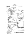
- the object of the invention is to produce a telescopic receptacle with or without a cover which latter is also capable of enlargement to fit the body when enlarged, the whole being especially .adapted 4for use for containing material such as index cards which increase in bulk and therefore retion with its parts distended;
- Fig. 2 is an enlarged horizontal section of one end of the box taken on the line 2-2 Aof Fig. 1;
- Fig. 3 is a transverse vertical section taken on the line 3 3 of Fig.- 2;
- Fig. 4 is a detail longitudinal section taken on the line 4-4 of Fig. 3;
- Fig. 5 is a perspective view showing a slightly different form of the invention;
- Fig. 6 is a longitudinal section thereof taken on the line 6-6 of Fig. 5;
- Fig. 7 is aperspective view showing a modified form of fastening means;
- Fig. 8 is a detail horizontal section taken on the line 8-8 of Fig. 7;
- l" ig. 9 is a ⁇ perspective view showing an lintermediate section in connection with the form o fastening illustrated in Figs. 7 and 8; and Fig. 10 is a detail horizontal section taken on the line 10#10 of Fig. 9.
- Fig. 11 represents a perspective view of a box equipped with anotherv form of this invention
- Fig. 12 is a transverse section thereof taken on the line 12-12 of Fig. 11
- Fig. 13 is a detail vertical longitudinal section taken on the line 13-13 of Fig. 12;
- Fig. 15 is a horizontal section taken on the line 15-15 of Fig. 14;
- Fig. 16 isv a. detail perspective view of a box end showing another forrn of the invention;
- Fig.. 17 is ahorizontal section thereof, taken on the line 17-17 of Fig. 16.
- a paperA box is shown especially adapted for use as a filing device for legal papers or card indexes but ⁇ the invention is notf'limited to such a form of box nor the material from which it is formed as the box is susceptible of wide'modifications both as to dimensions and material.
- the cover may be 'madeto telescope as shown in Figs. 1 and 2 or it may be dispensed with if no cover is required.
- the front. section of the box shown in the accompanying drawings comprises a panel 1 turned inward at its lowercedge tov forma bottom 2 and two ends 3 are turned inward from the extremity of the front panel and themselves have bottom flanges 4 turned undei ⁇ and secured beneath the bottom 2.
- the rear section comprises a rear panel 5,a bottom 6, two ends 7 and flanges 8 with the ends turned in under and secured to the bottom.
- the 4rear panel as illustrated also carries a cover 9 composed of two telescopieally engaged. sections 9* and 9".
- the bottom portion 6 formed on the rear panel 5- and the bottom 2 of the front panel 1 may be made sufficiently long to overlap a suflicient distance to provide for a predeterminedextensionv or expansibility of the box and the end members 3 of the front panel and 7 of the rear panel are correspondingly formed.
- These voverlapping bottom and end sections are telescopically engaged and slidably connected by means to be described whereby the box may be enlarged as its contents are increased and the cover sections 9a and 9" are corre'- spondingly formed.
- the means for providing a slidable connection between the4 corre'- sponding panels of the sections which constitutes the gist of this invention comprises slits 10 formed in either the bottom 2 or 6 the slits being here shown formed in the bottom member 6 of the rear panel and extending transversely thereof at-spaced intervals'and being arranged in parallel relation. Secured to the bottom 2 of the front them and the outer face of the bottom section 6 to permit the free movement of said section relatively to the section 2 but these washers may if desired, be dispensed with.
- Similar slits 10 are arranged in the end' section 7 of the rear panel -5 and are adapted to slidably engage with similar connecting elements 11 carried by the end members 3 of the front panel 1.
- the front panel 1 and rear panel 5 may be adjusted relatively to each other by simply moving them toward or away from ⁇ each other,-the slits 10-10 and the connecting elements 11-11 serving to guide the sections and hold them against separation, suilicient friction being exerted between the heads of the connecting elements 11 and the slit members to hold said sections in adjusted position.
- an intermediate section 14 may be arranged between the front and rear sections and as shown, this intermediate section comprises a bottom 15 overlying the rear edge of the bottom 2 of the front section and underlying the rear edge of the bottom 6 of the rear section and having upright ends llrising from the bottom 15, each standing inside one front end 3 and outside the adjacent rear end 7. It will be obvious that if the intermediate section were duplicated or multiplied, a much larger box than that shown would result.
- the headed connecting elements 11 are Acarried by the bottom 15 and the ends 16 thereof, said elements being arranged in pairs those of each pair being in transverse alinement and adapted to engage correspondingly arranged slits formed in the bottom sections 2 and 6 and the end sections 3 and 7 as is clearly shown in Figs. 4, '5 and 6.
- pairs of parallel slits 20 are arranged in one of the members and the connecting elements carried by the other member are shown in the form of metal strips 17 substantially U- shaped in form and which pass through the member to which they are to be secured and have their free ends turned inwardly after being passed through the slits 20 to form guides and retaining members for holding the sections of the box together as is shown clearly in-the drawings.
- pairs of parallel slits 20 are shown in this form, it is obvious that one of the slits may be omitted from each pair if desired and one end only of the ⁇ connecting element 17 engaged with the remaining slit but it is prei ferred that both ends be connected and two slits employed to strengthen the connection between the sections.
- FIGs. 9 and 10 the same form of fastening employed in Figs. 7 and 8 is used, the only difference betweenthe structure shown in these figures and that shown in Figs. 9 and 10 is that an intermediate section 14! is shown.
- FIGs. 11 to 13 another form of the invention is shown in which the overlapping ends 21 and 22 of the front and rear sections-1a and 2a of a box are slidably connected, one of said ends being provided with spaced slits 23 extending longitudinally of said end, the slits being alined with each other and disposed suiiicientlynear the edge of the ends 22 to provide ample room for the contraction of the sections, the extent of. which is limited by the engagement of said edges with the ends of the straps 24 disposed nearest the front section l".
- the end 22 of the rear section2a is shown overlapping end 21 of theV front section 1a and provided with these slits, but it is obvious that the positions lof these ends may be reversed if desired.
- the under lapping end, here shown as 21, is equipped with spaced straps 24 extending transversely of said end in planes at right angles to the slits 23 in theend 22 and positioned to re ister with said slits 23 and to be. slidably engaged therewith for adjustably connecting said front and rear sections of the box.
- T he straps 24 arel produced by forming pairs of parallel slits 25 in the ends 21, said slits extending transversely of saidends and beingspaced apart a distance-'equal to the width of the strap to be formed, preferably a distance slightly less than the length of the slits 23 and said slits 25 are of a length corresponding to the length of the strap.
- the portions ofthe ends opposite' the slits 23 therein are split transversely from said slits 23 to the' edge of the ends as shown in dotted lines at 26 in Fig. ⁇ 12, whereby these portions may be inserted under the straps 24, and after having been so inserted, the split or cut portions thereof are 'joined in any suitable manner, a strip of paper 27 being here shown glued over and connecting the split portions of the ends (see Fig. 13).
- the sections are slidably engaged and may be contracted or' expanded as desired, the extent of outward movement or expansion being limited bythe engagement of the outer walls of the slits 23 with the outer ends of the straps 24 as shown in Fig. 11.
- the extent of contraction Vis limited by the engagement of the edges of the ends 22 with the inner ends of the straps 24.
- Figs. '14 and 15 a slightly different form of the invention is shown, the ends 22 of the box being shown slit similarly to the form shown in Figs. 11 to 13, but these ends are not split from their edges inward to these slits, the assembling of the sections bein accomplished by severing the inner ends o the straps 24 (which in this form are extended .into the front section 1) and connecting them with the front section 1 in any suitable manner, an inner lining 28 being here shown glued to the inner face of the section 1 and to the outer face of which lining, the severed ends of the straps are glued, whereby the box sections are held in sliding engagement similarly to those shown in Figs. 11 to 13.
- the end 22 of the rear section 2aL underlaps the end 21 of the front section 1 and is provided withI pairs of parallel slits 25 extending transversely of said end 22 near the top and bottom thereof to form straps 24 which are slidably engaged -with straps 29 extending longitudinally of the end 21 ofthe front'section 1a near the outer edge of said end.
- the straps 29 of the end 21 are produced by forming longitudinally extending pairs of parallel slits 30 near the top and bottom of said end in position to register .with the straps 24 of the end ⁇ 22, said lslitsBO-"extending in planes at right angles to the slits 25 and the straps 29 also extend in planes at right angles to the straps 24.
- These4 straps 29 are split transversely intermediatel of their ends to permit the assembling o the sections and after they have been assed under the straps 24, the split ends o? said straps arev connected together in any suitable manner a strip 31 being here shown for this purpose glued to the inner face of the split ends of said strap 'whereby said ends are connected and the sections slidably engaged.
- a telescopic box composed of lappin sections, one of which has a pair of s aced slits extending in one direction an the other a pair of slits extending in a plane at right angles to the first mentioned pair forming straps adaptable for slidable engagement with each other to provide for the adjustment of said sections toward or away from each other.
- a telescopic box composed oflapping sections, one of which has a pair of arallel slits extending transversely thereof) forming a strap between them, the other section having parallel slits extending longitudinally thereof to form a strap, said straps being slidably engaged to provide for the adjustment of said sections toward or away from each other.
- a telescopic box composed of lapping sections, one of lwhich has a pair of parallel 4slits extending transversely thereof forming a strap between them, the other section having parallel slits extending longitudinally thereof to form a strap, said straps being slidably engaged to provide for the adjustment of said sections toward and away from each other, one of said straps being split transversely intermediate its ends to permit its engagement with the other strap and means for -connecting said split ends together.
Landscapes
- Engineering & Computer Science (AREA)
- Mechanical Engineering (AREA)
- Cartons (AREA)
Description
H. V. MARTIN.
EXPANSIBLB BOX.
APPLICATION FILED 1EB.9, 1914.
Patented Dec. 15y 1914.
3 SHEETS-SHEET 1.
] 1 1 u a 11 *oz H.-V. MARTIN.
BXPANSIBLE BOX.
APPLICATION FILED 11.3.9, 1914.
Patented Dec. 15` 1914.
H. V. MARTIN.
EXPANSIBLE BOX.
APPLICATION NLBD Num, 1914.
1,120,955. Patented Dec. 15, 1914.
3l/vi tu una Q Mw HOMER V. MARTIN, OF LINCOLN, NEBRASKA.
EXPANSIBLE BOX.
Specification of Letters Patent.-
Patented Dee. 15, v1914.
Appiication ined February 9, 1914. 'serian No. 817,596.
To all 'whom it may concern:
Beit known that I, HoMnR V. MARTIN, a citizen of the United States, residing at Lincoln, in the county of Lancaster and State of Nebraska, have invented certain new and useful Improvements -in Expansible Boxes; and I do declare the following to be a full, clear, and exact description of the invention,-sucli as will enable others skilled in the art to which it appertains to make and use the same.
This invention relates to receptacles such as-are usually made of paper and like stock and more particularly relates to such receptacles as are made from folded blanks.
The object of the invention is to produce a telescopic receptacle with or without a cover which latter is also capable of enlargement to fit the body when enlarged, the whole being especially .adapted 4for use for containing material such as index cards which increase in bulk and therefore retion with its parts distended; Fig. 2 is an enlarged horizontal section of one end of the box taken on the line 2-2 Aof Fig. 1; Fig. 3 is a transverse vertical section taken on the line 3 3 of Fig.- 2; Fig. 4 is a detail longitudinal section taken on the line 4-4 of Fig. 3; Fig. 5 is a perspective view showing a slightly different form of the invention; Fig. 6 is a longitudinal section thereof taken on the line 6-6 of Fig. 5; Fig. 7 is aperspective view showing a modified form of fastening means; Fig. 8 is a detail horizontal section taken on the line 8-8 of Fig. 7;
l" ig. 9 is a` perspective view showing an lintermediate section in connection with the form o fastening illustrated in Figs. 7 and 8; and Fig. 10 is a detail horizontal section taken on the line 10#10 of Fig. 9.
Fig. 11 represents a perspective view of a box equipped with anotherv form of this invention; Fig. 12 is a transverse section thereof taken on the line 12-12 of Fig. 11; Fig. 13 is a detail vertical longitudinal section taken on the line 13-13 of Fig. 12;
showing still another form of the invention;
Fig. 15 is a horizontal section taken on the line 15-15 of Fig. 14; Fig. 16 isv a. detail perspective view of a box end showing another forrn of the invention; Fig.. 17 is ahorizontal section thereof, taken on the line 17-17 of Fig. 16.
In the embodiment illustrated, a paperA box is shown especially adapted for use as a filing device for legal papers or card indexes but` the invention is notf'limited to such a form of box nor the material from which it is formed as the box is susceptible of wide'modifications both as to dimensions and material. A
l The cover may be 'madeto telescope as shown in Figs. 1 and 2 or it may be dispensed with if no cover is required. The front. section of the box shown in the accompanying drawings comprises a panel 1 turned inward at its lowercedge tov forma bottom 2 and two ends 3 are turned inward from the extremity of the front panel and themselves have bottom flanges 4 turned undei` and secured beneath the bottom 2. lIn like manner the rear section comprises a rear panel 5,a bottom 6, two ends 7 and flanges 8 with the ends turned in under and secured to the bottom. The 4rear panel as illustrated also carries a cover 9 composed of two telescopieally engaged. sections 9* and 9". The bottom portion 6 formed on the rear panel 5- and the bottom 2 of the front panel 1 may be made sufficiently long to overlap a suflicient distance to provide for a predeterminedextensionv or expansibility of the box and the end members 3 of the front panel and 7 of the rear panel are correspondingly formed. These voverlapping bottom and end sections are telescopically engaged and slidably connected by means to be described whereby the box may be enlarged as its contents are increased and the cover sections 9a and 9" are corre'- spondingly formed. 1
In Figs. 1 to 5 the means for providing a slidable connection between the4 corre'- sponding panels of the sections which constitutes the gist of this invention, comprises slits 10 formed in either the bottom 2 or 6 the slits being here shown formed in the bottom member 6 of the rear panel and extending transversely thereof at-spaced intervals'and being arranged in parallel relation. Secured to the bottom 2 of the front them and the outer face of the bottom section 6 to permit the free movement of said section relatively to the section 2 but these washers may if desired, be dispensed with.
If desired, an intermediate section 14 may be arranged between the front and rear sections and as shown, this intermediate section comprises a bottom 15 overlying the rear edge of the bottom 2 of the front section and underlying the rear edge of the bottom 6 of the rear section and having upright ends llrising from the bottom 15, each standing inside one front end 3 and outside the adjacent rear end 7. It will be obvious that if the intermediate section were duplicated or multiplied, a much larger box than that shown would result. When this intermediate section 14 is employed the headed connecting elements 11 are Acarried by the bottom 15 and the ends 16 thereof, said elements being arranged in pairs those of each pair being in transverse alinement and adapted to engage correspondingly arranged slits formed in the bottom sections 2 and 6 and the end sections 3 and 7 as is clearly shown in Figs. 4, '5 and 6.
In the form shown in Figs. 7 to 10, pairs of parallel slits 20 are arranged in one of the members and the connecting elements carried by the other member are shown in the form of metal strips 17 substantially U- shaped in form and which pass through the member to which they are to be secured and have their free ends turned inwardly after being passed through the slits 20 to form guides and retaining members for holding the sections of the box together as is shown clearly in-the drawings. While pairs of parallel slits 20 are shown in this form, it is obvious that one of the slits may be omitted from each pair if desired and one end only of the `connecting element 17 engaged with the remaining slit but it is prei ferred that both ends be connected and two slits employed to strengthen the connection between the sections.
In Figs. 9 and 10 the same form of fastening employed in Figs. 7 and 8 is used, the only difference betweenthe structure shown in these figures and that shown in Figs. 9 and 10 is that an intermediate section 14! is shown.
In Figs. 11 to 13, another form of the invention is shown in which the overlapping ends 21 and 22 of the front and rear sections-1a and 2a of a box are slidably connected, one of said ends being provided with spaced slits 23 extending longitudinally of said end, the slits being alined with each other and disposed suiiicientlynear the edge of the ends 22 to provide ample room for the contraction of the sections, the extent of. which is limited by the engagement of said edges with the ends of the straps 24 disposed nearest the front section l". In this instance, the end 22 of the rear section2a is shown overlapping end 21 of theV front section 1a and provided with these slits, but it is obvious that the positions lof these ends may be reversed if desired. The under lapping end, here shown as 21, is equipped with spaced straps 24 extending transversely of said end in planes at right angles to the slits 23 in theend 22 and positioned to re ister with said slits 23 and to be. slidably engaged therewith for adjustably connecting said front and rear sections of the box. T he straps 24 arel produced by forming pairs of parallel slits 25 in the ends 21, said slits extending transversely of saidends and beingspaced apart a distance-'equal to the width of the strap to be formed, preferably a distance slightly less than the length of the slits 23 and said slits 25 are of a length corresponding to the length of the strap.
To permit the assembling of the sections and their slidable connection, the portions ofthe ends opposite' the slits 23 therein are split transversely from said slits 23 to the' edge of the ends as shown in dotted lines at 26 in Fig. `12, whereby these portions may be inserted under the straps 24, and after having been so inserted, the split or cut portions thereof are 'joined in any suitable manner, a strip of paper 27 being here shown glued over and connecting the split portions of the ends (see Fig. 13). When so assembled, the sections are slidably engaged and may be contracted or' expanded as desired, the extent of outward movement or expansion being limited bythe engagement of the outer walls of the slits 23 with the outer ends of the straps 24 as shown in Fig. 11. The extent of contraction Vis limited by the engagement of the edges of the ends 22 with the inner ends of the straps 24.
In Figs. '14 and 15, a slightly different form of the invention is shown, the ends 22 of the box being shown slit similarly to the form shown in Figs. 11 to 13, but these ends are not split from their edges inward to these slits, the assembling of the sections bein accomplished by severing the inner ends o the straps 24 (which in this form are extended .into the front section 1) and connecting them with the front section 1 in any suitable manner, an inner lining 28 being here shown glued to the inner face of the section 1 and to the outer face of which lining, the severed ends of the straps are glued, whereby the box sections are held in sliding engagement similarly to those shown in Figs. 11 to 13.
In the form shown in Figs. 16 and 17, the end 22 of the rear section 2aL underlaps the end 21 of the front section 1 and is provided withI pairs of parallel slits 25 extending transversely of said end 22 near the top and bottom thereof to form straps 24 which are slidably engaged -with straps 29 extending longitudinally of the end 21 ofthe front'section 1a near the outer edge of said end. The straps 29 of the end 21 are produced by forming longitudinally extending pairs of parallel slits 30 near the top and bottom of said end in position to register .with the straps 24 of the end `22, said lslitsBO-"extending in planes at right angles to the slits 25 and the straps 29 also extend in planes at right angles to the straps 24. These4 straps 29 are split transversely intermediatel of their ends to permit the assembling o the sections and after they have been assed under the straps 24, the split ends o? said straps arev connected together in any suitable manner a strip 31 being here shown for this purpose glued to the inner face of the split ends of said strap 'whereby said ends are connected and the sections slidably engaged.
I claim as my invention:
1. A telescopic box composed of lappin sections, one of which has a pair of s aced slits extending in one direction an the other a pair of slits extending in a plane at right angles to the first mentioned pair forming straps adaptable for slidable engagement with each other to provide for the adjustment of said sections toward or away from each other.
2. A telescopic box composed oflapping sections, one of which has a pair of arallel slits extending transversely thereof) forming a strap between them, the other section having parallel slits extending longitudinally thereof to form a strap, said straps being slidably engaged to provide for the adjustment of said sections toward or away from each other.
3. A telescopic box composed of lapping sections, one of lwhich has a pair of parallel 4slits extending transversely thereof forming a strap between them, the other section having parallel slits extending longitudinally thereof to form a strap, said straps being slidably engaged to provide for the adjustment of said sections toward and away from each other, one of said straps being split transversely intermediate its ends to permit its engagement with the other strap and means for -connecting said split ends together.
In testimony whereof I have hereunto set my hand in presence of two subscribing witnesses.
HOMER V. MARTIN.
Witnesses E. M. WARNER, G. M. SEMANN.
Priority Applications (1)
| Application Number | Priority Date | Filing Date | Title |
|---|---|---|---|
| US81759614A US1120955A (en) | 1914-02-09 | 1914-02-09 | Expansible box. |
Applications Claiming Priority (1)
| Application Number | Priority Date | Filing Date | Title |
|---|---|---|---|
| US81759614A US1120955A (en) | 1914-02-09 | 1914-02-09 | Expansible box. |
Publications (1)
| Publication Number | Publication Date |
|---|---|
| US1120955A true US1120955A (en) | 1914-12-15 |
Family
ID=3189115
Family Applications (1)
| Application Number | Title | Priority Date | Filing Date |
|---|---|---|---|
| US81759614A Expired - Lifetime US1120955A (en) | 1914-02-09 | 1914-02-09 | Expansible box. |
Country Status (1)
| Country | Link |
|---|---|
| US (1) | US1120955A (en) |
Cited By (44)
| Publication number | Priority date | Publication date | Assignee | Title |
|---|---|---|---|---|
| US2595375A (en) * | 1949-04-04 | 1952-05-06 | William F Weirich | Dispensing unit for slot insulation material |
| US2598320A (en) * | 1948-08-02 | 1952-05-27 | Charles W Turbyfill | Adjustable container |
| US2709547A (en) * | 1953-01-26 | 1955-05-31 | Marion W Niedringhaus | Containers |
| US2730291A (en) * | 1949-03-25 | 1956-01-10 | Patent & Licensing Corp | Shipping container |
| US2771235A (en) * | 1949-07-11 | 1956-11-20 | Robert P Stephenson | Reinforced case |
| US2827222A (en) * | 1951-06-23 | 1958-03-18 | Sutherland Paper Co | Covered boxes or cartons |
| US2941670A (en) * | 1956-10-09 | 1960-06-21 | Gen Mills Inc | Merchandise display device |
| US2953244A (en) * | 1958-04-30 | 1960-09-20 | Curtis A Phillips | Adjustable display and storage device |
| US3013814A (en) * | 1958-06-16 | 1961-12-19 | Donald A Becks | Side-cart attachment for bicycles |
| US3071425A (en) * | 1960-08-19 | 1963-01-01 | Dade C West | Adjustable safety cabinet |
| US3463343A (en) * | 1967-08-28 | 1969-08-26 | Shell Oil Co | Adjustable circuit board box |
| US3691671A (en) * | 1971-01-11 | 1972-09-19 | Frederick H Kroll | Expandable doll house |
| US3700159A (en) * | 1970-11-09 | 1972-10-24 | Raymond J Beigel | Foldable container and blanks therefor |
| US3815799A (en) * | 1969-11-12 | 1974-06-11 | Emt Enterprises Inc | Litter container in an automobile seat assembly |
| US4025137A (en) * | 1975-07-25 | 1977-05-24 | Wyler Margaret C | Terraced telescopic storage shelves |
| US4184602A (en) * | 1978-05-30 | 1980-01-22 | Henry Moliard | Collapsible expansible container |
| US4416414A (en) * | 1982-07-22 | 1983-11-22 | Edgerton Allen T | Utility yard marker |
| US4941716A (en) * | 1986-01-03 | 1990-07-17 | Rome Eugene P | Cabinet construction |
| US5046607A (en) * | 1989-05-11 | 1991-09-10 | Focke & Co. (Gmbh) | Pack container, especially tray, for receiving (cardboard) packs |
| US5192019A (en) * | 1992-06-18 | 1993-03-09 | The Mike Meehan Company | Package product display box having adjustable length feature |
| US5230551A (en) * | 1991-09-03 | 1993-07-27 | Kramer Peter H | Concealed case chest of drawers |
| US5249381A (en) * | 1992-05-20 | 1993-10-05 | Raffy Panossian | Vehicle emergency sign |
| US5314046A (en) * | 1991-03-15 | 1994-05-24 | Fabio Pedrini | Expandable container with internal manual operation system |
| US5513580A (en) * | 1994-02-28 | 1996-05-07 | Franks; Curtis | Lockbox for installation in closets |
| US6116447A (en) * | 1999-07-19 | 2000-09-12 | Lucent Technologies Inc. | Expandable enclosure |
| US6227438B1 (en) * | 2000-03-07 | 2001-05-08 | Smurfit Stone Corporation | Expandable depth tray |
| US6796890B1 (en) * | 2003-02-20 | 2004-09-28 | Edward K Goldrick | Extendable wet saw water shield |
| US20070236111A1 (en) * | 2006-04-07 | 2007-10-11 | Fasteners For Retail, Inc. | Security case |
| US20080105594A1 (en) * | 2006-08-30 | 2008-05-08 | Henschel-Steinau, Inc. | Merchandise Packaging and display |
| EP1958546A1 (en) * | 2007-02-16 | 2008-08-20 | Energizer Group France | Display stand for assorted items |
| US7455214B2 (en) | 2006-04-13 | 2008-11-25 | Henkel Corporation | Adjustable volume storage container |
| US20110219988A1 (en) * | 2010-03-11 | 2011-09-15 | Stephens Jim O | Adjustable table and method |
| US20110233082A1 (en) * | 2010-03-25 | 2011-09-29 | Thomas Omer Muskopf | Electronic Media Storage Apparatus |
| US8608262B1 (en) * | 2010-11-15 | 2013-12-17 | Davide A. Daros | Expandable drawer |
| US20150282373A1 (en) * | 2014-03-25 | 2015-10-01 | Hubbell Incorporated | Telescoping security enclosure |
| US20180105317A1 (en) * | 2016-01-22 | 2018-04-19 | Boe Technology Group Co., Ltd. | Package box and liner for the same |
| US10028558B1 (en) * | 2015-05-15 | 2018-07-24 | Nancy Dou | Expandable and collapsible handbag |
| US20180274741A1 (en) * | 2017-03-24 | 2018-09-27 | Hubbell Incorporated | Adjustable luminaire housing |
| US20190274422A1 (en) * | 2018-03-09 | 2019-09-12 | Discovery Inc. | Expandable spice rack |
| CN111290215A (en) * | 2018-12-06 | 2020-06-16 | 家登精密工业股份有限公司 | Light shield container |
| CN112249478A (en) * | 2020-11-19 | 2021-01-22 | 马紫严 | Self-adaptation commodity circulation transport case of adjustable volume |
| US20220258040A1 (en) * | 2021-02-18 | 2022-08-18 | Pinnacle Puzzle Pty Ltd | Puzzle case |
| USD1039057S1 (en) | 2022-03-16 | 2024-08-13 | Pinnacle Puzzle Pty Ltd | Puzzle case |
| US20250331661A1 (en) * | 2024-04-29 | 2025-10-30 | Vira Insight, Llc | Security case |
-
1914
- 1914-02-09 US US81759614A patent/US1120955A/en not_active Expired - Lifetime
Cited By (52)
| Publication number | Priority date | Publication date | Assignee | Title |
|---|---|---|---|---|
| US2598320A (en) * | 1948-08-02 | 1952-05-27 | Charles W Turbyfill | Adjustable container |
| US2730291A (en) * | 1949-03-25 | 1956-01-10 | Patent & Licensing Corp | Shipping container |
| US2595375A (en) * | 1949-04-04 | 1952-05-06 | William F Weirich | Dispensing unit for slot insulation material |
| US2771235A (en) * | 1949-07-11 | 1956-11-20 | Robert P Stephenson | Reinforced case |
| US2827222A (en) * | 1951-06-23 | 1958-03-18 | Sutherland Paper Co | Covered boxes or cartons |
| US2709547A (en) * | 1953-01-26 | 1955-05-31 | Marion W Niedringhaus | Containers |
| US2941670A (en) * | 1956-10-09 | 1960-06-21 | Gen Mills Inc | Merchandise display device |
| US2953244A (en) * | 1958-04-30 | 1960-09-20 | Curtis A Phillips | Adjustable display and storage device |
| US3013814A (en) * | 1958-06-16 | 1961-12-19 | Donald A Becks | Side-cart attachment for bicycles |
| US3071425A (en) * | 1960-08-19 | 1963-01-01 | Dade C West | Adjustable safety cabinet |
| US3463343A (en) * | 1967-08-28 | 1969-08-26 | Shell Oil Co | Adjustable circuit board box |
| US3815799A (en) * | 1969-11-12 | 1974-06-11 | Emt Enterprises Inc | Litter container in an automobile seat assembly |
| US3700159A (en) * | 1970-11-09 | 1972-10-24 | Raymond J Beigel | Foldable container and blanks therefor |
| US3691671A (en) * | 1971-01-11 | 1972-09-19 | Frederick H Kroll | Expandable doll house |
| US4025137A (en) * | 1975-07-25 | 1977-05-24 | Wyler Margaret C | Terraced telescopic storage shelves |
| US4184602A (en) * | 1978-05-30 | 1980-01-22 | Henry Moliard | Collapsible expansible container |
| US4416414A (en) * | 1982-07-22 | 1983-11-22 | Edgerton Allen T | Utility yard marker |
| US4941716A (en) * | 1986-01-03 | 1990-07-17 | Rome Eugene P | Cabinet construction |
| US5046607A (en) * | 1989-05-11 | 1991-09-10 | Focke & Co. (Gmbh) | Pack container, especially tray, for receiving (cardboard) packs |
| US5314046A (en) * | 1991-03-15 | 1994-05-24 | Fabio Pedrini | Expandable container with internal manual operation system |
| US5230551A (en) * | 1991-09-03 | 1993-07-27 | Kramer Peter H | Concealed case chest of drawers |
| US5249381A (en) * | 1992-05-20 | 1993-10-05 | Raffy Panossian | Vehicle emergency sign |
| US5192019A (en) * | 1992-06-18 | 1993-03-09 | The Mike Meehan Company | Package product display box having adjustable length feature |
| US5513580A (en) * | 1994-02-28 | 1996-05-07 | Franks; Curtis | Lockbox for installation in closets |
| US6116447A (en) * | 1999-07-19 | 2000-09-12 | Lucent Technologies Inc. | Expandable enclosure |
| US6227438B1 (en) * | 2000-03-07 | 2001-05-08 | Smurfit Stone Corporation | Expandable depth tray |
| US6796890B1 (en) * | 2003-02-20 | 2004-09-28 | Edward K Goldrick | Extendable wet saw water shield |
| US20070236111A1 (en) * | 2006-04-07 | 2007-10-11 | Fasteners For Retail, Inc. | Security case |
| US7455214B2 (en) | 2006-04-13 | 2008-11-25 | Henkel Corporation | Adjustable volume storage container |
| US20080105594A1 (en) * | 2006-08-30 | 2008-05-08 | Henschel-Steinau, Inc. | Merchandise Packaging and display |
| US20100170825A1 (en) * | 2006-08-30 | 2010-07-08 | Henschel-Steinau, Inc. | Merchandise Packaging and Display |
| EP1958546A1 (en) * | 2007-02-16 | 2008-08-20 | Energizer Group France | Display stand for assorted items |
| FR2912627A1 (en) * | 2007-02-16 | 2008-08-22 | Energizer Group France Sa | DISPLAY FOR MISCELLANEOUS ARTICLES. |
| US20110219988A1 (en) * | 2010-03-11 | 2011-09-15 | Stephens Jim O | Adjustable table and method |
| US20110233082A1 (en) * | 2010-03-25 | 2011-09-29 | Thomas Omer Muskopf | Electronic Media Storage Apparatus |
| US8585159B2 (en) * | 2010-03-25 | 2013-11-19 | Thomas Omer Muskopf | Electronic media storage apparatus |
| US8608262B1 (en) * | 2010-11-15 | 2013-12-17 | Davide A. Daros | Expandable drawer |
| US20150282373A1 (en) * | 2014-03-25 | 2015-10-01 | Hubbell Incorporated | Telescoping security enclosure |
| US10104798B2 (en) * | 2014-03-25 | 2018-10-16 | Hubbell Incorporated | Telescoping security enclosure |
| US10028558B1 (en) * | 2015-05-15 | 2018-07-24 | Nancy Dou | Expandable and collapsible handbag |
| US20180105317A1 (en) * | 2016-01-22 | 2018-04-19 | Boe Technology Group Co., Ltd. | Package box and liner for the same |
| US10252833B2 (en) * | 2016-01-22 | 2019-04-09 | Boe Technology Group Co., Ltd. | Package box and liner for the same |
| US20180274741A1 (en) * | 2017-03-24 | 2018-09-27 | Hubbell Incorporated | Adjustable luminaire housing |
| US10591117B2 (en) * | 2017-03-24 | 2020-03-17 | Hubbell Incorporated | Luminaire housing having adjustable dimension |
| US20190274422A1 (en) * | 2018-03-09 | 2019-09-12 | Discovery Inc. | Expandable spice rack |
| CN111290215A (en) * | 2018-12-06 | 2020-06-16 | 家登精密工业股份有限公司 | Light shield container |
| US11333967B2 (en) * | 2018-12-06 | 2022-05-17 | Gudeng Precision Industrial Co., Ltd. | Reticle container |
| CN112249478A (en) * | 2020-11-19 | 2021-01-22 | 马紫严 | Self-adaptation commodity circulation transport case of adjustable volume |
| US20220258040A1 (en) * | 2021-02-18 | 2022-08-18 | Pinnacle Puzzle Pty Ltd | Puzzle case |
| US12251640B2 (en) * | 2021-02-18 | 2025-03-18 | Pinnacle Puzzle Pty Ltd | Puzzle case |
| USD1039057S1 (en) | 2022-03-16 | 2024-08-13 | Pinnacle Puzzle Pty Ltd | Puzzle case |
| US20250331661A1 (en) * | 2024-04-29 | 2025-10-30 | Vira Insight, Llc | Security case |
Similar Documents
| Publication | Publication Date | Title |
|---|---|---|
| US1120955A (en) | Expansible box. | |
| US3655112A (en) | Protective corner pad | |
| US1167847A (en) | Display-box. | |
| US2640644A (en) | Partition pad | |
| US781082A (en) | Carton or box. | |
| US649768A (en) | Interlocking return-envelop. | |
| US1293801A (en) | Folding box. | |
| US1890965A (en) | Box | |
| US109365A (en) | Improvement in cartridge-boxes | |
| US2591882A (en) | Wrapper or container of cardboard or like material | |
| US1808303A (en) | Display device | |
| US268542A (en) | Bruno ruckert | |
| US1373222A (en) | Expanding filing-pocket | |
| US735906A (en) | Folding box or crate. | |
| US10471767B2 (en) | Folder with movable divider | |
| US2772042A (en) | Cartons | |
| US1552519A (en) | Compression guide | |
| US1083461A (en) | Foldable display-box. | |
| US3291178A (en) | Pass case | |
| US1712779A (en) | Paper bag | |
| US1633904A (en) | Collapsible berry box | |
| US1645807A (en) | Box | |
| US1566972A (en) | Box | |
| US414077A (en) | Packing-box | |
| US188588A (en) | Improvement in bill-files |