US11213444B2 - On-bed state monitoring system - Google Patents
On-bed state monitoring system Download PDFInfo
- Publication number
- US11213444B2 US11213444B2 US16/633,961 US201816633961A US11213444B2 US 11213444 B2 US11213444 B2 US 11213444B2 US 201816633961 A US201816633961 A US 201816633961A US 11213444 B2 US11213444 B2 US 11213444B2
- Authority
- US
- United States
- Prior art keywords
- bed
- subject
- load
- sitting posture
- detectors
- Prior art date
- Legal status (The legal status is an assumption and is not a legal conclusion. Google has not performed a legal analysis and makes no representation as to the accuracy of the status listed.)
- Active
Links
Images




Classifications
-
- A—HUMAN NECESSITIES
- A61—MEDICAL OR VETERINARY SCIENCE; HYGIENE
- A61B—DIAGNOSIS; SURGERY; IDENTIFICATION
- A61B5/00—Measuring for diagnostic purposes; Identification of persons
- A61B5/0002—Remote monitoring of patients using telemetry, e.g. transmission of vital signals via a communication network
- A61B5/0015—Remote monitoring of patients using telemetry, e.g. transmission of vital signals via a communication network characterised by features of the telemetry system
- A61B5/002—Monitoring the patient using a local or closed circuit, e.g. in a room or building
-
- A—HUMAN NECESSITIES
- A61—MEDICAL OR VETERINARY SCIENCE; HYGIENE
- A61G—TRANSPORT, PERSONAL CONVEYANCES, OR ACCOMMODATION SPECIALLY ADAPTED FOR PATIENTS OR DISABLED PERSONS; OPERATING TABLES OR CHAIRS; CHAIRS FOR DENTISTRY; FUNERAL DEVICES
- A61G7/00—Beds specially adapted for nursing; Devices for lifting patients or disabled persons
- A61G7/05—Parts, details or accessories of beds
-
- A—HUMAN NECESSITIES
- A61—MEDICAL OR VETERINARY SCIENCE; HYGIENE
- A61B—DIAGNOSIS; SURGERY; IDENTIFICATION
- A61B5/00—Measuring for diagnostic purposes; Identification of persons
- A61B5/103—Measuring devices for testing the shape, pattern, colour, size or movement of the body or parts thereof, for diagnostic purposes
- A61B5/1036—Measuring load distribution, e.g. podologic studies
-
- A—HUMAN NECESSITIES
- A61—MEDICAL OR VETERINARY SCIENCE; HYGIENE
- A61B—DIAGNOSIS; SURGERY; IDENTIFICATION
- A61B5/00—Measuring for diagnostic purposes; Identification of persons
- A61B5/103—Measuring devices for testing the shape, pattern, colour, size or movement of the body or parts thereof, for diagnostic purposes
- A61B5/11—Measuring movement of the entire body or parts thereof, e.g. head or hand tremor or mobility of a limb
- A61B5/1113—Local tracking of patients, e.g. in a hospital or private home
- A61B5/1115—Monitoring leaving of a patient support, e.g. a bed or a wheelchair
-
- A—HUMAN NECESSITIES
- A61—MEDICAL OR VETERINARY SCIENCE; HYGIENE
- A61B—DIAGNOSIS; SURGERY; IDENTIFICATION
- A61B5/00—Measuring for diagnostic purposes; Identification of persons
- A61B5/103—Measuring devices for testing the shape, pattern, colour, size or movement of the body or parts thereof, for diagnostic purposes
- A61B5/11—Measuring movement of the entire body or parts thereof, e.g. head or hand tremor or mobility of a limb
- A61B5/1116—Determining posture transitions
-
- A—HUMAN NECESSITIES
- A61—MEDICAL OR VETERINARY SCIENCE; HYGIENE
- A61B—DIAGNOSIS; SURGERY; IDENTIFICATION
- A61B5/00—Measuring for diagnostic purposes; Identification of persons
- A61B5/45—For evaluating or diagnosing the musculoskeletal system or teeth
- A61B5/4538—Evaluating a particular part of the muscoloskeletal system or a particular medical condition
- A61B5/4561—Evaluating static posture, e.g. undesirable back curvature
-
- A—HUMAN NECESSITIES
- A61—MEDICAL OR VETERINARY SCIENCE; HYGIENE
- A61B—DIAGNOSIS; SURGERY; IDENTIFICATION
- A61B5/00—Measuring for diagnostic purposes; Identification of persons
- A61B5/68—Arrangements of detecting, measuring or recording means, e.g. sensors, in relation to patient
- A61B5/6887—Arrangements of detecting, measuring or recording means, e.g. sensors, in relation to patient mounted on external non-worn devices, e.g. non-medical devices
- A61B5/6892—Mats
-
- A—HUMAN NECESSITIES
- A61—MEDICAL OR VETERINARY SCIENCE; HYGIENE
- A61B—DIAGNOSIS; SURGERY; IDENTIFICATION
- A61B5/00—Measuring for diagnostic purposes; Identification of persons
- A61B5/72—Signal processing specially adapted for physiological signals or for diagnostic purposes
- A61B5/7271—Specific aspects of physiological measurement analysis
- A61B5/7275—Determining trends in physiological measurement data; Predicting development of a medical condition based on physiological measurements, e.g. determining a risk factor
-
- G—PHYSICS
- G08—SIGNALLING
- G08B—SIGNALLING SYSTEMS, e.g. PERSONAL CALLING SYSTEMS; ORDER TELEGRAPHS; ALARM SYSTEMS
- G08B21/00—Alarms responsive to a single specified undesired or abnormal condition and not otherwise provided for
- G08B21/02—Alarms for ensuring the safety of persons
-
- G—PHYSICS
- G08—SIGNALLING
- G08B—SIGNALLING SYSTEMS, e.g. PERSONAL CALLING SYSTEMS; ORDER TELEGRAPHS; ALARM SYSTEMS
- G08B25/00—Alarm systems in which the location of the alarm condition is signalled to a central station, e.g. fire or police telegraphic systems
- G08B25/01—Alarm systems in which the location of the alarm condition is signalled to a central station, e.g. fire or police telegraphic systems characterised by the transmission medium
- G08B25/04—Alarm systems in which the location of the alarm condition is signalled to a central station, e.g. fire or police telegraphic systems characterised by the transmission medium using a single signalling line, e.g. in a closed loop
-
- G—PHYSICS
- G16—INFORMATION AND COMMUNICATION TECHNOLOGY [ICT] SPECIALLY ADAPTED FOR SPECIFIC APPLICATION FIELDS
- G16H—HEALTHCARE INFORMATICS, i.e. INFORMATION AND COMMUNICATION TECHNOLOGY [ICT] SPECIALLY ADAPTED FOR THE HANDLING OR PROCESSING OF MEDICAL OR HEALTHCARE DATA
- G16H40/00—ICT specially adapted for the management or administration of healthcare resources or facilities; ICT specially adapted for the management or operation of medical equipment or devices
- G16H40/60—ICT specially adapted for the management or administration of healthcare resources or facilities; ICT specially adapted for the management or operation of medical equipment or devices for the operation of medical equipment or devices
- G16H40/63—ICT specially adapted for the management or administration of healthcare resources or facilities; ICT specially adapted for the management or operation of medical equipment or devices for the operation of medical equipment or devices for local operation
-
- A—HUMAN NECESSITIES
- A61—MEDICAL OR VETERINARY SCIENCE; HYGIENE
- A61B—DIAGNOSIS; SURGERY; IDENTIFICATION
- A61B2562/00—Details of sensors; Constructional details of sensor housings or probes; Accessories for sensors
- A61B2562/02—Details of sensors specially adapted for in-vivo measurements
- A61B2562/0247—Pressure sensors
-
- A—HUMAN NECESSITIES
- A61—MEDICAL OR VETERINARY SCIENCE; HYGIENE
- A61B—DIAGNOSIS; SURGERY; IDENTIFICATION
- A61B2562/00—Details of sensors; Constructional details of sensor housings or probes; Accessories for sensors
- A61B2562/02—Details of sensors specially adapted for in-vivo measurements
- A61B2562/0252—Load cells
-
- A—HUMAN NECESSITIES
- A61—MEDICAL OR VETERINARY SCIENCE; HYGIENE
- A61B—DIAGNOSIS; SURGERY; IDENTIFICATION
- A61B2562/00—Details of sensors; Constructional details of sensor housings or probes; Accessories for sensors
- A61B2562/02—Details of sensors specially adapted for in-vivo measurements
- A61B2562/0261—Strain gauges
-
- A—HUMAN NECESSITIES
- A61—MEDICAL OR VETERINARY SCIENCE; HYGIENE
- A61B—DIAGNOSIS; SURGERY; IDENTIFICATION
- A61B2562/00—Details of sensors; Constructional details of sensor housings or probes; Accessories for sensors
- A61B2562/04—Arrangements of multiple sensors of the same type
- A61B2562/046—Arrangements of multiple sensors of the same type in a matrix array
-
- A—HUMAN NECESSITIES
- A61—MEDICAL OR VETERINARY SCIENCE; HYGIENE
- A61G—TRANSPORT, PERSONAL CONVEYANCES, OR ACCOMMODATION SPECIALLY ADAPTED FOR PATIENTS OR DISABLED PERSONS; OPERATING TABLES OR CHAIRS; CHAIRS FOR DENTISTRY; FUNERAL DEVICES
- A61G2203/00—General characteristics of devices
- A61G2203/30—General characteristics of devices characterised by sensor means
- A61G2203/32—General characteristics of devices characterised by sensor means for force
Definitions
- the present invention relates to an in-bed state (on-bed state) monitoring system for monitoring an in-bed state of a (human) subject on a bed on the basis of detection values of load detectors.
- a state of a subject on the basis of such a (body weight) load of the subject on a bed as detected by load detectors.
- a load detectors For the sites of medical treatment and caregiving, it is proposed to determine whether the subject is present in the bed or absent from the bed, estimate the respiratory rate of the subject, etc., on the basis of the detected load.
- Patent Literatures 1 to 3 each disclose an in-bed state monitoring system in which the load applied on the bedding portion of a bed is detected with four load detecting means and, notify the information that the in-bed position of the subject is located in an end part area of the bedding portion of the bed on the basis of a determining step carried out to fit the load values outputted from the four load detecting means into a plurality of determination formulas.
- Patent Literatures 1 to 3 each disclose that determination is also made on whether or not the subject is in an edge sitting posture where he or she sits at an end part of the bed.
- a first object of the present invention is to provide an in-bed state monitoring system capable of predicting the situation of a subject on a bed being about to reach an edge sitting posture at an earlier time.
- a second object of the present invention is to provide the in-bed state monitoring system capable of determining that the subject on the bed has reached the edge sitting posture at a higher precision.
- an in-bed state monitoring system for monitoring an in-bed state of a subject on a bed, the system including:
- an edge sitting posture determining unit configured to predict that the subject is reaching a state of edge sitting posture based on a change in a magnitude relation between detection values from two load detectors, which are of the four load detectors and are placed to interpose the bed between the two load detectors in a diagonal direction of the bed.
- the edge sitting posture determining unit may be configured to predict that the subject is reaching the state of edge sitting posture based on a reversal of the magnitude relation between the detection values from the two load detectors placed to interpose the bed between the two load detectors in the diagonal direction of the bed.
- the in-bed state monitoring system may further include a body motion determining unit configured to determine whether a body motion of the subject is present or not based on a detection value of at least one load detector of the four load detectors; and may further include a body position determining unit configured to determine a position of the subject in a width direction of the bed based on detection values of first and second load detectors, the first load detector being at least one load detector of the four load detectors and being placed at one side of the bed in the width direction of the bed, the second load detector being at least one load detector of the four load detectors and being placed at other side of the bed in the width direction of the bed.
- the edge sitting posture determining unit may be configured to determine whether the subject is in the state of edge sitting posture or not based on a determination result of the body motion determining unit and a determination result of the body position determining unit.
- the edge sitting posture determining unit may be configured to determine whether the subject is in the state of edge sitting posture or not based on the determination result of the body motion determining unit and the determination result of the body position determining unit, in a case that the edge sitting posture determining unit has predicted that the subject is reaching the state of the edge sitting posture.
- an in-bed state monitoring system for monitoring an in-bed state of a subject on a bed, the system including:
- a body motion determining unit configured to determine whether a body motion of the subject is present or not based on a detection value of at least one load detector of the four load detectors
- a body position determining unit configured to determine a position of the subject in a width direction of the bed based on detection values of first and second load detectors, the first load detector being at least one load detector of the four load detectors and being placed at one side of the bed in the width direction of the bed, the second load detector being at least one load detector of the four load detectors and being placed at other side of the bed in the width direction of the bed; and an edge sitting posture determining unit configured to determine whether the subject is in a state of edge sitting posture or not based on a determination result of the body motion determining unit and a determination result of the body position determining unit.
- the in-bed state monitoring system may further include a notifying unit configured to carry out a notification based on a determination result of the edge sitting posture determining unit.
- a bed system including:
- the in-bed state monitoring system according to any one of the first aspect and the second aspect.
- the in-bed state monitoring system of the present invention it is possible to predict the situation of a subject on a bed being about to reach an edge sitting posture at an earlier time.
- the in-bed state monitoring system of the present invention it is possible to determine that the subject on the bed has reached the edge sitting posture at a higher precision.
- FIG. 1 is a block diagram depicting a configuration of an in-bed state monitoring system according to an embodiment of the present invention.
- FIG. 2 is an illustrative view depicting an arrangement of load detectors for a bed.
- FIG. 3 is a flow chart depicting a method for monitoring an in-bed state by using the in-bed state monitoring system.
- FIG. 4 is a graph schematically depicting an example of a load value detected by a load detector.
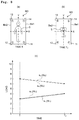
- FIGS. 5( a ), 5( b ), and 5( c ) are views for explaining a principle used to predict an edge sitting posture of a subject, depicting an aspect of variation of detection signals of the four detectors during the period from a state of lying supine of the subject in the bed center to reaching a state of edge sitting posture.
- FIGS. 6( a ), 6( b ), and 6( c ) are views for explaining the principle used to predict the edge sitting posture of the subject, depicting the aspect of variation of detection signals of the four detectors during the period from the state of lying supine of the subject in a position deviating to one side from the bed center in a width direction, to reaching the state of edge sitting posture on the other side of the bed in the width direction.
- FIGS. 7( a ), 7( b ), and 7( c ) are views for explaining the principle used to predict the edge sitting posture of the subject, depicting the aspect of variation of detection signals of the four detectors during the period from the state of lying supine of the subject in a position deviating to one side from the bed center in the width direction, to reaching the state of edge sitting posture on the same one side.
- FIGS. 8( a ), 8( b ), and 8( c ) are views for explaining the principle used to predict the edge sitting posture of the subject, depicting the aspect of variation of detection signals of the four detectors during the period from the state of lying supine of the subject in the bed center to reaching a state of sitting on the bed center with the upper body being upright.
- FIGS. 9( a ), 9( b ), and 9( c ) are views for explaining the principle used to predict the edge sitting posture of the subject, depicting the aspect of variation of detection signals of the four detectors during the period from the state of lying supine of the subject in the bed center to reaching the state of lying prone in a position deviating to one side from the bed center in the width direction.
- FIG. 10( a ) is an example of edge sitting posture prediction performed by using the in-bed state monitoring system of the embodiment, and examples of load signals s 1 , s 2 , s 3 , and s 4 used to determine the edge sitting posture.
- FIGS. 10( b ) and 10( c ) depict a determination result of a body motion determining unit and a determination result of a body position determining unit, during the period when the load signals of FIG. 10( a ) are obtained.
- FIG. 11 is a block diagram depicting an overall configuration of a bed system according to a modified embodiment of the present invention.
- an in-bed state monitoring system (on-bed state monitoring system) 100 ( FIG. 1 ) according to an embodiment of the present invention, with an example of using the above system with a bed BD ( FIG. 2 ) to monitor an in-bed state (present-in-bed state, present-on-bed state) of a subject S on the bed BD.
- the axis X of the bed BD is defined as the axis extending in the breadthwise (widthwise) direction of the bed BD and passing through the center O
- the axis Y of the bed BD is defined as the axis extending in the lengthwise (longitudinal or up/down) direction of the bed BD and passing through the center O.
- the positive side of the axis X is the right side of the center O of the bed BD whereas the negative side of the axis X is the left side thereof, and the positive side of the axis Y is the upper side of the center O of the bed BD whereas the negative side of the axis Y is the lower side thereof.
- the subject S lies on the bed BD
- generally he or she lies along the axis Y and the head is placed on the positive side and the feet are placed on the negative side in the axis-Y direction.
- the in-bed state monitoring system 100 of this embodiment primarily has a load detecting unit 1 , a control unit 3 , a storage unit 4 , and a notifying unit 5 .
- the load detecting unit 1 and the control unit 3 are connected via an A/D converting unit 2 .
- the control unit 3 is further connected to an input unit 6 .
- the load detecting unit 1 includes four load detectors 11 , 12 , 13 , and 14 .
- Each of the load detectors 11 , 12 , 13 , and 14 is a load detector for detecting a load by using, for example, a beam-type load cell.
- a load detector is disclosed, for example, in Japanese Patent No. 4829020 and Japanese Patent No. 4002905.
- Each of the load detectors 11 , 12 , 13 , and 14 is connected to the A/D converting unit 2 by way of wiring or wirelessly.
- the four load detectors 11 to 14 of the load detecting unit 1 are arranged respectively under casters C 1 , C 2 , C 3 , and C 4 fitted on the lower ends of legs BL 1 , BL 2 , BL 3 , and BL 4 at the four corners of the bed BD used by the subject S.
- the A/D converting unit 2 includes an A/D convertor connected respectively to the load detecting unit 1 and the control unit 3 by way of wiring or wirelessly, to convert analog signals from the load detecting unit 1 to digital signals.
- the control unit 3 is a dedicated or general-purpose computer inside which a body motion determining unit 31 , a body position determining unit 32 , and an edge sitting posture (edge sitting position) determining unit 33 are constructed.
- the storage unit 4 is a storage device for storing data used in the in-bed state monitoring system 100 and, for example, can use a hard disk (magnetic disk) for that purpose.
- the notifying unit 5 is a part for performing predetermined notifications on the basis of the output from the control unit 3 , including a monitor 51 such as a liquid crystal monitor or the like for visual (image) notification, and a speaker 52 for auditory notification.
- the input unit 6 is an interface for performing predetermined inputs for the control unit 3 , which may be a keyboard and a mouse.
- to monitor the in-bed state of the subject is, in particular for example, to predict a situation of the subject reaching (or being about to reach) a state of the edge sitting posture, and/or to determine whether or not the subject has reached the edge sitting posture.
- the term “(state of) edge sitting posture” means that the subject is in a state of sitting at an end (edge) of the bed in the width direction thereof.
- the edge sitting posture (edge sitting position) includes both of the state that the subject's feet are in contact with the floor surface under the bed and the state that subject's feet are not in contact with the floor surface.
- Monitoring the in-bed state of the subject by using the in-bed state monitoring system 100 includes: as depicted in the flow chart of FIG. 3 , a load detecting step S 1 for detecting the load of the subject; a body motion determining step S 2 for determining whether or not there is a body motion of the subject on the basis of the detected load; a body position determining step S 3 for determining whether or not the subject has approached an end of the bed on the basis of the detected load; an edge sitting posture determining step S 4 for predicting that the subject is to reach the edge sitting posture and/or determining whether or not the subject has reached the edge sitting posture on the basis of at least one of the following determination results: the load of the subject detected in the load detecting step S 1 , whether or not there is a body motion of the subject determined in the body motion determining step S 2 , and whether or not the subject has approached an end of the bed determined in the body position determining step S 3 ; and a notifying step S 5 for performing predetermined a notification on the basis of the determination result
- the load detectors 11 , 12 , 13 , and 14 are used to detect the load of the subject S on the bed BD.
- the load of the subject S on the bed BD is applied dispersively to the load detectors 11 to 14 arranged respectively under the legs BL 1 to BL 4 of the bed BD at the four corners, and is detected dispersively by the four load detectors.
- Each of the load detectors 11 to 14 detects the load (a variation in load), and outputs the result as an analog signal to the A/D converting unit 2 .
- the A/D converting unit 2 converts the analog signal into a digital signal through a sampling period of 5 milliseconds, for example, and then outputs the digital signal (to be referred to below as “load signal”) to the control unit 3 .
- load signals s 1 , s 2 , s 3 , and s 4 will be used to refer respectively to the load signals obtained by the A/D converting unit 2 converting the analog signals outputted from the load detectors 11 , 12 , 13 , and 14 into the digital format.
- a body motion determining unit 31 uses at least one of the load signals s 1 to s 4 , to determine whether or not there is a body motion of subject S.
- body motion refers to any motion of the subject's head, torso (body-trunk), or four limbs.
- the body motion does not include motions of internal organs, blood vessels and the like along with the respirations, heartbeats, and the like.
- the body motion can be classified into a large body motion along with the motion of the subject S in the torso (body-trunk), and a small body motion along with the motion of the subject only in the four limbs and/or the head.
- One example of the large body motion is turn-over, sit-up or get-up, or the like, whereas one example of the small body motion is, a motion of the hands, the feet, the head or the like during sleep.
- the body motion determining unit 31 determines whether or not there is a body motion arising in the subject S on the basis of the flowing principle.
- FIG. 4 depicts such a schematic waveform of the load signal s 1 from the load detector 11 as obtained in a predetermined period including times t 0 , t 1 , and t 2 .
- the load signal s 1 during this period vibrates only a little, reflecting a motion of the internal organs, blood vessels and the like of the subject in accordance with the respirations and heartbeats of the subject S, such that the amount of variation is small.
- the period P 1 when the subject S has no body motion there is a small variation in the sampling value of the load signal s 1 .
- the variation of the sampling value of the load signal s 2 from the load detector 11 becomes small in the period when the subject S has no body motion but becomes large in the period when the subject S has a body motion. Much the same is true on the load signals s 2 , s 2 , and s 4 from the load detectors 12 , 13 , and 14 .
- the body motion determining unit 13 calculates, for at least one of the load signals s 2 to s 4 from the load detectors 11 to 14 , a standard deviation ⁇ which indicates the magnitude of variation of the sampling value included in a predetermined period (such as 5 seconds as one example), and determines whether or not there is a body motion arising in the subject S on the basis of a comparison between the calculated standard deviation ⁇ and a predetermined threshold value ⁇ th .
- the body motion determining unit 13 determines that there is no body motion arising in the subject S during that period.
- the body motion determining unit 13 determines that there is a body motion arising in the subject S during that period. Note that whether or not the subject S has a body motion may be determined by comparing a dispersion ⁇ 2 with a predetermined threshold value ⁇ 2 th , instead of the standard deviation ⁇ .
- the body position determining unit 32 determines whether or not the body position of the subject S has approached (is close to) an end of the bed BD in the width direction (in the axis-X direction), on the basis of the load signals s 1 to s 4 from the load detectors 11 to 14 .
- a first bed end Be 1 refers to the end of the bed BD on the positive side in the axis-X direction
- a second bed end Be 2 refers to the end of the bed BD on the negative side in the axis-X direction ( FIG. 2 ).
- the first bed end Be 1 and the second bed end Be 2 are collectively referred to as “the bed end”.
- the body position determining unit 32 finds a value X by using the following formula 1, where W 1 , W 2 , W 3 , and W 4 are the sampling values at different sampling times of the load signals s 1 , s 2 , s 3 , and s 4 from the load detectors 11 , 12 , 13 , and 14 , respectively.
- X
- the body position determining unit 32 determines whether or not the subject S has approached (is close to) the bed end by using the found value X according to the following principle.
- the load detectors 11 to 14 included in the in-bed state monitoring system 100 of this embodiment are arranged under the legs BL 1 and BL 4 on the side of the first bed end Be 1 whereas the load detectors 12 and 13 are arranged under the legs BL 2 and BL 3 on the side of the second bed end Be 2 .
- the sampling values W 1 and W 4 of the load signals s 1 and s 4 from the load detectors 11 and 14 increase accordingly whereas the sampling values W 2 and W 3 of the load signals s 2 and s 3 from the load detectors 12 and 13 decrease accordingly.
- the value X found with the formula 1 increases accordingly.
- the sampling values W 2 and W 3 of the load signals s 2 and s 2 from the load detectors 12 and 13 increase accordingly whereas the sampling values W 1 and W 4 of the load signals s 2 and s 4 from the load detectors 11 and 14 decrease accordingly.
- the value X found with the formula 1 increases accordingly.
- the body position determining unit 32 determines whether or not the subject S has approached the bed end. In particular, the body position determining unit 32 compares the value X found with the formula 1 with a predetermined threshold value X th , to determine that the subject S has approached (is close to) the bed end at the point when the value X exceeds the predetermined threshold value X th .
- the predetermined threshold value X th can be set as appropriate. If it is desirable to determine that the subject has approached the bed end at an earlier point of time (that is, at a point of time when there is a comparatively long distance between the subject S and the bed end), then the predetermined threshold value X th is set to a comparatively small value. Conversely, if it is desirable to determine that the subject has approached the bed end at an later point of time (that is, at a point of time when the distance between the subject S and the bed end has become comparatively short), then the predetermined threshold value X th is set to a comparatively large value.
- the bed BD may also fall into a more or less three-point supported state (that is, the bed BD is no longer supported uniformly by the legs BL 1 to BL 4 at the four corners, but three of the four legs increase in the share of support whereas the other one decreases in the share of support).
- the load of the bed BD with the subject S thereupon is applied more to three of the load detectors 11 to 14 under the legs BL 1 to BL 4 at the four corners, but less to the other one.
- the body position determining unit 32 of this embodiment determines the body position of the subject S with the formula 1 which comprehensively uses the sampling values W 1 to W 4 of the load signals s 1 to s 4 from the load detectors 11 to 14 ; therefore, even if the bed BD falls into the more or less three-point supported state, it is still possible to offset (balance), to a certain degree, the possible errors arising in the values of the sampling values W 1 to W 4 due to the occurrence of the more or less three-point supported state, thereby restraining the precision of determination from decreasing.
- the edge sitting posture determining unit 33 predicts a situation of the subject S being about to reach the state of edge sitting posture on the basis of the load signals s 1 to s 4 from the load detectors 11 to 14 . Then, after predicting the situation of the subject S being about to reach the edge sitting posture, the edge sitting posture determining unit 33 determines whether or not the subject S has actually reached the edge sitting posture on the basis of the determination result in the body motion determining step S 2 and the determination result in the body position determining step S 3 .
- the edge sitting posture determining unit 33 predicts the situation of the subject S being about to reach the edge sitting posture on the basis of the following principle.
- the inventor of the present invention has made a number of researches on the relation between the aspect of motion of the subject S on the bed BD and the aspect of variation in the load signals s 1 to s 4 from the load detectors 11 to 14 according to the motion of the subject S, in order to detect the subject S reaching the edge sitting posture at an earlier time.
- the edge sitting posture determining unit 33 predicts the situation of the subject S being about to reach the edge sitting posture on the basis of the reversal of the magnitude relation either between the sampling value W 1 of the load signal s 1 from the load detector 11 and the sampling value W 3 of the load signal s 3 from the load detector 13 , or between the sampling value W 2 of the load signal s 2 from the load detector 12 and the sampling value W 4 of the load signal s 4 from the load detector 14 .
- the load of the subject S is applied to the load detectors 11 , 12 , 13 , and 14 provided at the four corners of the bed BD at the ratio of approximately 3:3:7:7. Therefore, the sampling values W 1 , W 2 , W 3 , and W 4 of the load signals s 1 , s 2 , s 3 , and s 4 from the load detectors 11 , 12 , 13 , and 14 are also approximately 3:3:7:7 in magnitude.
- the proportions of the load applied to the load detectors 11 and 12 arranged on the feet side of the subject S are smaller than proportions of the load applied to the load detectors 13 and 14 arranged on the head side of the subject S. This is because the ratio of weight between the upper half and the lower half of the human body is approximately 7:3.
- the sampling values W 1 , W 2 , W 3 , and W 4 of the load signals s 1 , s 2 , s 3 , and s 4 from the load detectors 11 , 12 , 13 , and 14 are also approximately 1:9:9:1 in magnitude.
- the sampling value W 4 of the load signal s 4 is larger than the sampling value W 2 of the load signal s 2 ( FIG. 5( c ) ).
- FIG. 5( c ) is such a graph as to schematically depict an aspect of variation in the sampling values W 1 to W 4 of the load signals s 1 to s 4 during the period from the time T 1 when the subject S is lying supine in the center of the bed to the time T 2 when the subject is sitting at the edge of the bed at the second bed end Be 2 . It is recognizable, from this graph as well, that the magnitude relation reverses between the sampling value W 2 of the load signal s 2 of the load detector 12 and the sampling value W 4 of the load signal s 4 of the load detector 14 , right before the point for the subject S to reach the edge sitting posture during the period from the time T 1 to the time T 2 . Further, it is also recognizable that the reversal of the magnitude relation of the sampling values only arises between the sampling value W 2 of the load signal s 2 and the sampling value W 4 of the load signal s 4 , but does not arise between the other sampling values.
- the sampling values W 1 , W 2 , W 3 , and W 4 of the load signals s 1 , s 2 , s 3 , and s 4 are also approximately 4:2:6:8 in magnitude.
- the sampling values W 1 , W 2 , W 3 , and W 4 of the load signals s 1 , s 2 , s 3 , and s 4 from the load detectors 11 , 12 , 13 , and 14 are approximately 1:9:9:1 in magnitude.
- the sampling value W 4 of the load signal s 4 from the load detector 14 is larger than the sampling value W 2 of the load signal s 2 from the load detector 12 ( FIG. 6( c ) ).
- FIG. 6( c ) is another graph schematically depicting the aspect of variation in the sampling values W 1 to W 4 of the load signals s 2 to s 4 during the period from the time T 1 to the time T 2 . It is recognizable, from this graph as well, that the magnitude relation reverses between the sampling value W 2 of the load signal s 2 of the load detector 12 and the sampling value W 4 of the load signal s 4 of the load detector 14 , right before the point for the subject S to reach the edge sitting posture during the period from the time T 1 to the time T 2 .
- the sampling values W 1 , W 2 , W 3 , and W 4 of the load signals s 1 , s 2 , s 3 , and s 4 are also approximately 2:4:8:6 in magnitude.
- the sampling values W 1 , W 2 , W 3 , and W 4 of the load signals s 1 , s 2 , s 3 , and s 4 from the load detectors 11 , 12 , 13 , and 14 are approximately 1:9:9:1 in magnitude.
- FIG. 7( c ) is another graph schematically depicting the aspect of variation in the sampling values W 1 to W 4 of the load signals s 2 to s 4 during the period from the time T 1 to the time T 2 . From this graph, it is also recognizable that the magnitude relation reverses between the sampling value W 2 of the load signal s 2 of the load detector 12 and the sampling value W 4 of the load signal s 4 of the load detector 14 , right before the point for the subject S to reach the edge sitting posture during the period from the time T 1 to the time T 2 . Further, it is also recognizable that the reversal of the magnitude relation of the sampling values only arises between the sampling value W 2 of the load signal s 2 and the sampling value W 4 of the load signal s 4 , but does not arise between the other sampling values.
- sampling value of a first load detector provided to locate on the feet side of the subject when the subject S is lying and locate on the side of the subject being present when the subject S is sitting at the edge of the bed, increases greatly during the period in which the subject moves to the edge sitting posture; and the sampling value of a second load detector, provided to locate on the head side of the subject when the subject S is lying and locate on the side of the subject being absent when the subject S is sitting at the edge of the bed (that is, the second load detector is arranged at the diagonal position of the bed BD from the first load detector), decreases greatly during the period in which the subject moves to the edge sitting posture.
- the center of gravity of the subject S is positioned on the positive side of the bed BD in the axis-Y direction.
- the center of gravity of the subject S is positioned on the negative side in the axis-Y direction. Then, within the period in which the subject S moves to the state of sitting at the edge of the bed at the second bed end Be 2 in almost the center in the axis-Y direction, the magnitude relation reverses between the sampling value W 1 of the load signal s 1 of the load detector 11 and the sampling value W 3 of the load signal s 3 of the load detector 13 .
- edge sitting posture determining unit 33 of the in-bed state monitoring system 100 of this embodiment may predict that the subject S is reaching the edge sitting posture at the point when the sampling values of the load signals conform with each other between a pair of load detectors arranged to interpose the bed BD along a diagonal direction (a pair of load detectors arranged at diagonal positions of the bed BD).
- the expression “predicting that the subject is reaching a state of edge sitting posture based on a change in a magnitude relation between detection values (signal values; sampling values) from two load detectors” includes both of predicting the state of edge sitting posture based on the reversal of the detection values from the two load detectors and predicting the state of edge sitting posture based on the conformation of the detection values from the two load detectors.
- the conformation and the reversal of the magnitude relation between the load signal s 2 and the load signal s 4 can be taken as such a phenomenon, for example, that a standard deviation between the sampling value W 2 of the load signal s 2 at a predetermined time T between the time T 1 and the time T 2 , and the sampling value W 4 of the load signal s 4 at the time T decreases as time proceeds from the time T 1 toward the time T 2 , and then increases again.
- the expression “predicting that the subject is reaching a state of edge sitting posture based on a change in a magnitude relation between detection values (signal values; sampling values) from two load detectors” described in the present invention also includes the case where the conformation and the reversal of the detection values from two load detectors are taken with such a different point of view as, for example, the change in standard deviation between the two detection values, and predicts the edge sitting posture on the basis of such change.
- the sampling values W 1 , W 2 , W 3 , and W 4 of the load signals s 1 , s 2 , s 3 , and s 4 from the load detectors 11 , 12 , 13 , and 14 are approximately 3:3:7:7 in magnitude.
- FIG. 8( c ) is another graph schematically depicting the aspect of variation in the sampling values W 1 to W 4 of the load signals s 1 to s 4 during the period from the time T 1 to the time T 2 . From this graph as well, it is recognizable that the magnitude relation neither reverses (changes) between the sampling value W 1 of the load signal s 1 of the load detector 11 and the sampling value W 3 of the load signal s 3 of the load detector 13 , nor reverses (changes) between the sampling value W 2 of the load signal s 2 of the load detector 12 and the sampling value W 4 of the load signal s 4 of the load detector 14 .
- the sampling values W 1 , W 2 , W 3 , and W 4 of the load signals s 1 , s 2 , s 3 , and s 4 from the load detectors 11 , 12 , 13 , and 14 are approximately 3:3:7:7 in magnitude.
- the sampling values W 1 , W 2 , W 3 , and W 4 of the load signals s 1 , s 2 , s 3 , and s 4 from the load detectors 11 , 12 , 13 , and 14 are approximately 4:2:6:8 in magnitude.
- FIG. 9( c ) is another graph schematically depicting the aspect of variation in the sampling values W 1 to W 4 of the load signals s 1 to s 4 during the period from the time T 1 to the time T 2 . From this graph as well, it is recognizable that the magnitude relation neither reverses (changes) between the sampling value W 1 of the load signal s 1 from the load detector 11 and the sampling value W 3 of the load signal s 3 from the load detector 13 , nor reverses (changes) between the sampling value W 2 of the load signal s 2 from the load detector 12 and the sampling value W 4 of the load signal s 4 from the load detector 14 .
- the edge sitting posture determining unit 33 determines whether or not the subject S has actually reached the edge sitting posture. This determination is, in particular, carried out in the following manner.
- the edge sitting posture determining unit 33 receives that determination result and places a flag of “Body Motion” on. Further, if the body position determining unit 32 determines in the body position determining step S 3 that the subject S has approached the bed end, then the edge sitting posture determining unit 33 receives that determination result and places a flag of “Bed End” on.
- the edge sitting posture determining unit 33 After predicting the situation of the subject S being about to reach the edge sitting posture, the edge sitting posture determining unit 33 confirms whether or not the “Body Motion” flag and the “Bed End” flag are on. Then, if both of the “Body Motion” flag and the “Bed End” flag are on or turned on, then the edge sitting posture determining unit 33 determines that the subject S has reached the edge sitting posture.
- the notifying unit 5 notifies the nurses, caregivers, and/or others who are the users of the in-bed state monitoring system 100 of the results of the prediction and determination of the edge sitting posture determining unit 33 .
- the notification may be carried out by the notifying unit 5 in various forms including the visual notification using the monitor 51 and/or the auditory notification using the speaker 52 .
- the information therefor is displayed on the monitor 51 with an icon or the like.
- some kind of notifying sound may be emitted from the speaker 52 .
- the notification carried out at the point of determining that the subject S has reached the edge sitting posture may give an impression of higher degree of emergency, compared to the notification carried out at the point of predicting the situation of the subject S being about to reach the edge sitting posture. For example, if the notification is visual, then the former may use red color for its icon whereas the latter may use yellow color for its icon, etc.
- Nurses, caregivers, and/or others can head for the bed BD according to the notification made by the notifying unit 5 . Then, after confirming the situation of the subject S (that is, a hospitalized patient, care receiver in a care facility, or another) having reached the edge sitting posture, it is possible to help him or her stand up, move to the wheelchair, etc., as necessary.
- the subject S that is, a hospitalized patient, care receiver in a care facility, or another
- This example shows the following aspect of variation in the actual posture of the subject S.
- the graph of FIG. 10( a ) shows the aspect of variation in the load signals s 1 to s 4 from the load detectors 11 to 14 during the period of the subject S moving in the above manner.
- the signal is distorted due to the startup of the in-bed state monitoring system 100 , and therefore the data are ineffective.
- each of the load signals s 1 to s 4 is stable. Further, it is also recognizable that during this period, the load signal s 3 and s 4 from the load detectors 13 and 14 positioned on the head side of the subject S are larger (in value) than the load signal s 1 and s 2 from the load detectors 11 and 12 positioned on the feet side of the subject S; the load signal s 2 and s 4 are larger than the load signal s 1 and s 3 because the body axis of the subject S is inclined to the axis Y.
- FIG. 10( b ) and FIG. 10( c ) respectively show the result of the body motion determining unit 31 determining whether or not there is a body motion of the subject S, and the result of the body position determining unit 32 determining whether or not the subject S has approached the bed end, during the period of the subject S moving in the above manner.
- the “1” on the vertical axis means that the “Body Motion” flag is on in the edge sitting posture determining unit 33
- the “0” means that the “Body Motion” flag is not on in the edge sitting posture determining unit 33 , respectively.
- the body motion determining unit 31 determines that there is a body motion over the entire period from the time 0 sec to the time 10 sec. This can be improved by adjusting a threshold value ⁇ th compared with the standard deviation ⁇ for determining whether or not there is a body motion.
- the “1” on the vertical axis means that the “Bed End” flag is on in the edge sitting posture determining unit 33
- the “0” means that the “Bed End” flag is not on in the edge sitting posture determining unit 33 , respectively. From FIG. 10( c ) , it is recognizable that the “Bed End” flag was on during the period from the time 4.5 sec to the time 5.0 sec or so in which the subject S has reached the edge sitting posture sitting at the second bed end Be 2 , to the time 6.3 sec when the subject S has left the bed.
- the in-bed state monitoring system 100 predicted the situation of the subject S being about to reach the edge sitting posture at the time 3.7 sec, and then determined that the subject S has reached the edge sitting posture at the time 4.7 sec, on the basis of the load signals s 1 to s 4 depicted in FIG. 10( a ) and the determination results of the body motion determining unit 31 and the body position determining unit 32 depicted in FIGS. 10( b ) and 10( c ) . That is, the in-bed state monitoring system 100 made a correct prediction and determination according to the aspect of variation in the actual posture of the subject S as described above.
- the in-bed state monitoring system 100 of this embodiment is capable of predicting the situation of the subject S being about to reach the edge sitting posture before the subject S has actually reached the edge sitting posture, on the basis of the load signals s 1 to s 4 from the load detectors 11 to 14 . Therefore, according to the in-bed state monitoring system 100 of this embodiment, it is possible to notify the nurses, caregivers, and/or others who are the users of the in-bed state monitoring system 100 of the situation at an earlier time and, based on this notification, it is possible for the nurses, caregivers, and/or others to help the hospitalized patients and/or others on the bed BD in a more appropriate manner. By virtue of this, it is possible to more reliably prevent accidents such as falls, tumbles and the like which may be happen when the hospitalized patients and/or others are leaving the bed.
- the in-bed state monitoring system 100 of this embodiment determines whether or not the subject S has reached the edge sitting posture after predicting the situation of the subject S being about to reach the edge sitting posture on the basis of the load signals s 1 to s 4 from the load detectors 11 to 14 . In this manner, because consideration is made also on the history of the load variation before the subject S reaches the edge sitting posture for determining the edge sitting posture, the determination has a high precision.
- the in-bed state monitoring system 100 of this embodiment takes into consideration not only the result of the body position determining unit 32 determining whether or not the subject S has approached the bed end but also the result of the body motion determining unit 31 determining whether or not the subject S is performing a body motion, for determining whether or not the subject S has reached the edge sitting posture. Because consideration is made on whether or not there is a body motion in the above manner for the determination, it is possible to carry out the determination at a higher precision by way of distinguishing the case where the subject S has actually reached the edge sitting posture from the case where, for example, the subject S is sleeping in the vicinity of the bed end without any body motion.
- the in-bed state monitoring system 100 of this embodiment uses the load detectors 11 to 14 arranged under the legs BL 1 to BL 4 of the bed BD to determine the in-bed state of the subject S. Therefore, it is not necessary to attach any measuring device to the body of the subject S so that the subject S will not feel discomfort and a sense of incongruity.
- the body motion determining unit 31 selects at least any one of the load signals s 1 to s 4 from the load detectors 11 to 14 to calculate the standard deviation ⁇ for the selected load signal(s).
- the body motion determining unit 31 may calculate the standard deviation ⁇ for all of the load signals s 1 to s 4 and, in this case for example, the body motion determining unit 31 may determine whether or not the subject S has a body motion by way of comparing the maximal value of the calculated standard deviations ⁇ with the predetermined threshold value ⁇ th .
- the body motion determining unit 31 uses at least one of the load signals s 1 to s 4 as it is from the A/D converting unit 2 to calculate the standard deviation ⁇ .
- the body motion determining unit 31 may perform a down sampling for at least one of the load signals s 1 to s 4 to calculate the standard deviation ⁇ thereafter.
- the body motion determining unit 31 may find the standard deviation ⁇ by using the signal after carrying out a motion averaging process over 15 seconds, for example, to block the DC component for at least one of the load signals s 1 to s 4 . In the in-bed state monitoring system 100 of the above embodiment, the body motion determining unit 31 may find the standard deviation ⁇ by using the signal after carrying out both the above down sampling and the above motion averaging process.
- the body motion determining unit 31 may determine whether or not there is a body motion without calculating the standard deviation ⁇ .
- the body motion determining unit 31 may calculate the position of the center of gravity G of the subject S and a center of gravity locus GT which is a temporal change thereof, by using the load signals s 1 to s 4 . Then, during a predetermined period, if the center of gravity G moves beyond a predetermined distance, then the body motion determining unit 31 may determine that there is a body motion in the subject S.
- the body position determining unit 32 may determine whether or not the subject S has approached the bed end, on the basis of comparing a predetermined threshold value with the absolute value of the difference between any of the sampling values W 1 and W 4 of the load signals s 1 and s 4 from the load detectors 11 and 14 provided at the side of the first bed end Be 1 and any of the sampling values W 2 and W 4 of the load signals s 2 and s 3 from the load detectors 12 and 13 provided at the side of the second bed end Be 2 .
- the value X′ expressed by X′
- also increases as the subject S is approaching the bed end. Therefore, it is possible to determine whether or not the subject S has approached the bed end on the basis of comparing the value X′ with a predetermined threshold value X′ th .
- the body position determining unit 32 may determine whether or not the subject S has approached the bed end on the basis of the distance between the position of the center of gravity G of the subject S and the first and second bed ends Be 1 and Be 2 .
- the edge sitting posture determining unit 33 may predict whether the subject S is about to reach the edge sitting posture at the first bed end Be 1 or at the second bed end Be 2 as well.
- the edge sitting posture determining unit 33 predicts that the subject S is about to reach the edge sitting posture at the first bed end Be 1 in a case that exchange is detected in the magnitude relation between the sampling value W 1 of the load signal S 1 from the load detector 11 and the sampling value W 3 of the load signal s 3 from the load detector 13 , and predicts that the subject S is about to reach the edge sitting posture at the second bed end Be 2 in a case that exchange is detected in the magnitude relation between the sampling value W 2 of the load signal S 2 from the load detector 12 and the sampling value W 4 of the load signal s 4 from the load detector 14 .
- the prediction may further take the position of the center of gravity G into referential consideration.
- the edge sitting posture determining unit 33 determines the edge sitting posture by using the determination result of the body motion determining unit 31 and the determination result of the body position determining unit 32 after predicting the situation of the subject S being about to reach the edge sitting posture on the basis of the load signals s 1 to s 4 .
- the present invention is not limited to that.
- the edge sitting posture determining unit 33 may confirm whether or not the “Body Motion” flag is on the basis of the determination result of the body motion determining unit 31 and whether or not the “Bed End” flag is on on the basis of the determination result of the body position determining unit 32 , so as to determine that the subject S has reached the edge sitting posture in a case that both flags are on.
- the edge sitting posture determining unit 33 is configured to be capable of both predicting the edge sitting posture and determining the edge sitting posture.
- the edge sitting posture determining unit 33 may be configured to be capable of either predicting the edge sitting posture or determining the edge sitting posture.
- the load detectors 11 to 14 are not limited to load sensors using beam-type load cells but, for example, force sensors are also usable.
- the load detectors 11 to 14 are arranged respectively on the undersides of the casters C 1 to C 4 attached to the lower ends of the legs BL 1 to BL 4 of the bed BD.
- Each of the load detectors 11 to 14 may be provided respectively between one of the four legs of the bed BD and the board of the bed BD.
- each of the load detectors 11 to 14 may be provided between each of the upper legs and each of the lower legs.
- the load detectors 11 to 14 may be formed integral with or removable from the bed BD to construct a bed system BDS comprising the bed BD and the in-bed state monitoring system 100 of this embodiment ( FIG. 11 ).
- the load detecting unit 1 between the load detecting unit 1 and the A/D converting unit 2 , it is possible to provide a signal amplifying unit to amplify the load signals from the load detecting unit 1 , and/or a filtering unit to eliminate the noises from the load signals.
- the notifying unit 5 may include a simplified visible display means such as a printer for printing out information showing the biological state, a lamp displaying the biological state, and/or the like, instead of the monitor 51 or in addition to the monitor 51 . Further, the notifying unit 5 may include a vibration generating unit for carrying out the notification by way of vibration, instead of the speaker 52 or in addition to the speaker 52 .
- in-bed state monitoring system of the present invention is used in hospitals and/or care facilities, then it is possible to prevent accidents such as falls, tumbles and the like from happening when the hospitalized patients and/or care receivers in the care facilities are leaving the bed.
Landscapes
- Health & Medical Sciences (AREA)
- Life Sciences & Earth Sciences (AREA)
- Engineering & Computer Science (AREA)
- General Health & Medical Sciences (AREA)
- Public Health (AREA)
- Physics & Mathematics (AREA)
- Biomedical Technology (AREA)
- Veterinary Medicine (AREA)
- Animal Behavior & Ethology (AREA)
- Medical Informatics (AREA)
- Pathology (AREA)
- Biophysics (AREA)
- Surgery (AREA)
- Molecular Biology (AREA)
- Heart & Thoracic Surgery (AREA)
- Business, Economics & Management (AREA)
- Dentistry (AREA)
- Oral & Maxillofacial Surgery (AREA)
- Emergency Management (AREA)
- General Physics & Mathematics (AREA)
- Physiology (AREA)
- Nursing (AREA)
- Physical Education & Sports Medicine (AREA)
- Epidemiology (AREA)
- Primary Health Care (AREA)
- General Business, Economics & Management (AREA)
- Artificial Intelligence (AREA)
- Rheumatology (AREA)
- Computer Networks & Wireless Communication (AREA)
- Orthopedic Medicine & Surgery (AREA)
- Computer Vision & Pattern Recognition (AREA)
- Psychiatry (AREA)
- Signal Processing (AREA)
- Measurement Of The Respiration, Hearing Ability, Form, And Blood Characteristics Of Living Organisms (AREA)
- Invalid Beds And Related Equipment (AREA)
- Measuring And Recording Apparatus For Diagnosis (AREA)
- Emergency Alarm Devices (AREA)
- Alarm Systems (AREA)
Applications Claiming Priority (4)
| Application Number | Priority Date | Filing Date | Title |
|---|---|---|---|
| JP2017-145040 | 2017-07-27 | ||
| JP2017145040A JP6434580B1 (ja) | 2017-07-27 | 2017-07-27 | 在床状態監視システム |
| JPJP2017-145040 | 2017-07-27 | ||
| PCT/JP2018/028046 WO2019022186A1 (fr) | 2017-07-27 | 2018-07-26 | Système de surveillance de l'état d'alitement |
Publications (2)
| Publication Number | Publication Date |
|---|---|
| US20200155392A1 US20200155392A1 (en) | 2020-05-21 |
| US11213444B2 true US11213444B2 (en) | 2022-01-04 |
Family
ID=64560751
Family Applications (1)
| Application Number | Title | Priority Date | Filing Date |
|---|---|---|---|
| US16/633,961 Active US11213444B2 (en) | 2017-07-27 | 2018-07-26 | On-bed state monitoring system |
Country Status (5)
| Country | Link |
|---|---|
| US (1) | US11213444B2 (fr) |
| EP (1) | EP3659565B1 (fr) |
| JP (1) | JP6434580B1 (fr) |
| CN (1) | CN110913819A (fr) |
| WO (1) | WO2019022186A1 (fr) |
Families Citing this family (5)
| Publication number | Priority date | Publication date | Assignee | Title |
|---|---|---|---|---|
| US11908570B1 (en) * | 2019-03-20 | 2024-02-20 | Allscripts Software, Llc | Apparatus, system and method for data diffusion in a medical computer system |
| US11908571B1 (en) * | 2019-03-20 | 2024-02-20 | Allscripts Software, Llc | Apparatus, system and method for data diffusion in a medical computer system |
| JP7267104B2 (ja) * | 2019-05-24 | 2023-05-01 | パラマウントベッド株式会社 | システム |
| US11883158B2 (en) | 2020-06-05 | 2024-01-30 | Hill-Rom Services, Inc. | Predicting occupant exit from support apparatus |
| US20220265168A1 (en) * | 2021-02-23 | 2022-08-25 | Samsung Electronics Co., Ltd. | Real-time limb motion tracking |
Citations (18)
| Publication number | Priority date | Publication date | Assignee | Title |
|---|---|---|---|---|
| JPH11290394A (ja) | 1998-04-08 | 1999-10-26 | Yamato Scale Co Ltd | 寝台装置 |
| JP4002905B2 (ja) | 2004-04-13 | 2007-11-07 | 日本圧着端子製造株式会社 | 荷重スケール及びこれを用いた荷重スケールシステム |
| JP2007330659A (ja) | 2006-06-19 | 2007-12-27 | Showa Denko Kk | ベッドの在床状況検出方法 |
| US20080132808A1 (en) | 2002-07-17 | 2008-06-05 | Lokhorst David M | Bed occupant monitoring system |
| US20080217074A1 (en) | 2007-03-07 | 2008-09-11 | Omron Healthcare Co., Ltd. | Scale |
| JP2008206869A (ja) | 2007-02-27 | 2008-09-11 | Paramount Bed Co Ltd | 寝台装置 |
| CN101313877A (zh) | 2008-05-07 | 2008-12-03 | 上海理工大学 | 具有防坠功能的智能护理床 |
| US20090260158A1 (en) * | 2006-01-20 | 2009-10-22 | Hiroki Kazuno | Bed Apparatus Provided With Bed-Departure Prediction and Detection System |
| US20100231376A1 (en) | 2006-06-19 | 2010-09-16 | Showa Denko K.K. | Method of detecting presence of subject on bed |
| JP4676924B2 (ja) | 2006-06-19 | 2011-04-27 | 昭和電工株式会社 | ベッドの在床状況検出方法 |
| JP2011130827A (ja) | 2009-12-22 | 2011-07-07 | Aisin Seiki Co Ltd | 在床状態判定装置 |
| JP4829020B2 (ja) | 2006-07-10 | 2011-11-30 | 昭和電工株式会社 | ベッドの荷重検出器 |
| US20130205501A1 (en) * | 2012-02-15 | 2013-08-15 | Stryker Corporation | Patient support apparatus and controls therefor |
| JP2015008920A (ja) | 2013-06-28 | 2015-01-19 | 住友理工株式会社 | 離床センサおよび離床検出方法 |
| US20150221202A1 (en) * | 2014-02-04 | 2015-08-06 | Covidien Lp | Preventing falls using posture and movement detection |
| US20160007886A1 (en) * | 2013-06-28 | 2016-01-14 | Sumitomo Riko Company Limited | Bed-leaving sensor and bed-leaving detection method |
| US20160220114A1 (en) | 2013-09-13 | 2016-08-04 | Konica Minolta, Inc. | Monitor Subject Monitoring Device And Method, And Monitor Subject Monitoring System |
| WO2016152424A1 (fr) | 2015-03-26 | 2016-09-29 | コニカミノルタ株式会社 | Dispositif et procédé d'affichage de système de surveillance de personne surveillée et système de surveillance de personne surveillée |
Family Cites Families (1)
| Publication number | Priority date | Publication date | Assignee | Title |
|---|---|---|---|---|
| JPS4829020B1 (fr) | 1969-10-18 | 1973-09-06 |
-
2017
- 2017-07-27 JP JP2017145040A patent/JP6434580B1/ja active Active
-
2018
- 2018-07-26 WO PCT/JP2018/028046 patent/WO2019022186A1/fr not_active Ceased
- 2018-07-26 US US16/633,961 patent/US11213444B2/en active Active
- 2018-07-26 EP EP18837425.0A patent/EP3659565B1/fr active Active
- 2018-07-26 CN CN201880047206.6A patent/CN110913819A/zh active Pending
Patent Citations (25)
| Publication number | Priority date | Publication date | Assignee | Title |
|---|---|---|---|---|
| JPH11290394A (ja) | 1998-04-08 | 1999-10-26 | Yamato Scale Co Ltd | 寝台装置 |
| US20080132808A1 (en) | 2002-07-17 | 2008-06-05 | Lokhorst David M | Bed occupant monitoring system |
| JP4002905B2 (ja) | 2004-04-13 | 2007-11-07 | 日本圧着端子製造株式会社 | 荷重スケール及びこれを用いた荷重スケールシステム |
| US20090260158A1 (en) * | 2006-01-20 | 2009-10-22 | Hiroki Kazuno | Bed Apparatus Provided With Bed-Departure Prediction and Detection System |
| JP2007330659A (ja) | 2006-06-19 | 2007-12-27 | Showa Denko Kk | ベッドの在床状況検出方法 |
| JP4965904B2 (ja) | 2006-06-19 | 2012-07-04 | 昭和電工株式会社 | ベッドの在床状況検出方法 |
| JP2012250046A (ja) | 2006-06-19 | 2012-12-20 | Showa Denko Kk | ベッドの在床状況検出方法 |
| JP5086996B2 (ja) | 2006-06-19 | 2012-11-28 | 昭和電工株式会社 | ベッドの在床状況検出方法 |
| US20100231376A1 (en) | 2006-06-19 | 2010-09-16 | Showa Denko K.K. | Method of detecting presence of subject on bed |
| JP4676924B2 (ja) | 2006-06-19 | 2011-04-27 | 昭和電工株式会社 | ベッドの在床状況検出方法 |
| US8279057B2 (en) | 2006-06-19 | 2012-10-02 | Showa Denko K.K. | Method of detecting presence of subject on bed |
| JP4829020B2 (ja) | 2006-07-10 | 2011-11-30 | 昭和電工株式会社 | ベッドの荷重検出器 |
| JP2008206869A (ja) | 2007-02-27 | 2008-09-11 | Paramount Bed Co Ltd | 寝台装置 |
| JP2008216155A (ja) | 2007-03-07 | 2008-09-18 | Omron Healthcare Co Ltd | 体重計 |
| US20080217074A1 (en) | 2007-03-07 | 2008-09-11 | Omron Healthcare Co., Ltd. | Scale |
| CN101313877A (zh) | 2008-05-07 | 2008-12-03 | 上海理工大学 | 具有防坠功能的智能护理床 |
| JP2011130827A (ja) | 2009-12-22 | 2011-07-07 | Aisin Seiki Co Ltd | 在床状態判定装置 |
| US20130205501A1 (en) * | 2012-02-15 | 2013-08-15 | Stryker Corporation | Patient support apparatus and controls therefor |
| JP2015008920A (ja) | 2013-06-28 | 2015-01-19 | 住友理工株式会社 | 離床センサおよび離床検出方法 |
| US20160007887A1 (en) * | 2013-06-28 | 2016-01-14 | Sumitomo Riko Company Limited | Bed-leaving sensor and bed-leaving detection method |
| US20160007886A1 (en) * | 2013-06-28 | 2016-01-14 | Sumitomo Riko Company Limited | Bed-leaving sensor and bed-leaving detection method |
| US9795321B2 (en) | 2013-06-28 | 2017-10-24 | Sumitomo Riko Company Limited | Bed-leaving sensor and bed-leaving detection method |
| US20160220114A1 (en) | 2013-09-13 | 2016-08-04 | Konica Minolta, Inc. | Monitor Subject Monitoring Device And Method, And Monitor Subject Monitoring System |
| US20150221202A1 (en) * | 2014-02-04 | 2015-08-06 | Covidien Lp | Preventing falls using posture and movement detection |
| WO2016152424A1 (fr) | 2015-03-26 | 2016-09-29 | コニカミノルタ株式会社 | Dispositif et procédé d'affichage de système de surveillance de personne surveillée et système de surveillance de personne surveillée |
Non-Patent Citations (7)
| Title |
|---|
| Decision to Grant a Patent dated Nov. 6, 2018 for corresponding Japanese Application No. 2017-145040 and English translation. |
| English translation of Written Opinion for corresponding International Application No. PCT/JP2018/028046 dated Sep. 18, 2018. |
| Extended European Search Report dated Jan. 12, 2021 for corresponding European Application No. 18837425.0. |
| International Search Report for corresponding International Application No. PCT/JP2018/028046 dated Sep. 18, 2018. |
| Office Action dated Jan. 22, 2021 for corresponding Chinese Application No. 201880047206.6 and English translation. |
| Office Action dated Oct. 21, 2021 for corresponding Chinese Application No. 201880047206.6 and English translation. |
| Written Opinion for corresponding International Application No. PCT/JP2018/028046 dated Sep. 18, 2018. |
Also Published As
| Publication number | Publication date |
|---|---|
| US20200155392A1 (en) | 2020-05-21 |
| JP2019024674A (ja) | 2019-02-21 |
| EP3659565B1 (fr) | 2023-06-21 |
| EP3659565A4 (fr) | 2021-01-27 |
| EP3659565A1 (fr) | 2020-06-03 |
| JP6434580B1 (ja) | 2018-12-05 |
| WO2019022186A1 (fr) | 2019-01-31 |
| CN110913819A (zh) | 2020-03-24 |
Similar Documents
| Publication | Publication Date | Title |
|---|---|---|
| US11213444B2 (en) | On-bed state monitoring system | |
| US9931085B2 (en) | Device and method of monitoring a position and predicting an exit of a subject on or from a substrate | |
| JP4921233B2 (ja) | ベッドの在床検知方法 | |
| JP6139615B2 (ja) | 異常通報システム、異常通報方法及びプログラム | |
| CN111195180A (zh) | 用于确定目标压力损伤评分并基于其更改治疗计划的系统和方法 | |
| EP3766424B1 (fr) | Système de détermination de sommeil/veille | |
| JP6706536B2 (ja) | 使用者位置検出装置及び方法 | |
| US20230157584A1 (en) | Body motion determination system | |
| US12226204B2 (en) | Body motion determination system and biological state monitoring system | |
| TW202129605A (zh) | 狀態判定方法、狀態判定裝置、狀態判定系統、狀態判定程式及記錄媒體 | |
| JP2012040441A (ja) | ベッドの在床監視システム | |
| WO2016186067A1 (fr) | Dispositif et procédé de détection de position d'utilisateur | |
| JP2019051097A (ja) | 在床状態見守りシステム | |
| CN111788614B (zh) | 在床状态监视系统以及具备其的床 | |
| JP2018015210A (ja) | 在床状態モニタリングシステム | |
| JP2018015209A (ja) | 在床状態モニタリングシステム | |
| JP2020174967A (ja) | 情報処理装置、褥瘡リスク評価方法及び褥瘡リスク評価プログラム | |
| JP2017205409A (ja) | 在床状態モニタリングシステム | |
| WO2016159347A1 (fr) | Dispositif de détermination d'état | |
| WO2021095332A1 (fr) | Système de surveillance de position du corps et système de lit |
Legal Events
| Date | Code | Title | Description |
|---|---|---|---|
| FEPP | Fee payment procedure |
Free format text: ENTITY STATUS SET TO UNDISCOUNTED (ORIGINAL EVENT CODE: BIG.); ENTITY STATUS OF PATENT OWNER: LARGE ENTITY |
|
| STPP | Information on status: patent application and granting procedure in general |
Free format text: NOTICE OF ALLOWANCE MAILED -- APPLICATION RECEIVED IN OFFICE OF PUBLICATIONS |
|
| STPP | Information on status: patent application and granting procedure in general |
Free format text: PUBLICATIONS -- ISSUE FEE PAYMENT VERIFIED |
|
| STPP | Information on status: patent application and granting procedure in general |
Free format text: NON FINAL ACTION MAILED |
|
| STPP | Information on status: patent application and granting procedure in general |
Free format text: RESPONSE TO NON-FINAL OFFICE ACTION ENTERED AND FORWARDED TO EXAMINER |
|
| STPP | Information on status: patent application and granting procedure in general |
Free format text: NOTICE OF ALLOWANCE MAILED -- APPLICATION RECEIVED IN OFFICE OF PUBLICATIONS |
|
| STPP | Information on status: patent application and granting procedure in general |
Free format text: AWAITING TC RESP., ISSUE FEE NOT PAID |
|
| STPP | Information on status: patent application and granting procedure in general |
Free format text: NOTICE OF ALLOWANCE MAILED -- APPLICATION RECEIVED IN OFFICE OF PUBLICATIONS |
|
| STPP | Information on status: patent application and granting procedure in general |
Free format text: PUBLICATIONS -- ISSUE FEE PAYMENT VERIFIED |
|
| STPP | Information on status: patent application and granting procedure in general |
Free format text: PUBLICATIONS -- ISSUE FEE PAYMENT VERIFIED |
|
| STCF | Information on status: patent grant |
Free format text: PATENTED CASE |
|
| MAFP | Maintenance fee payment |
Free format text: PAYMENT OF MAINTENANCE FEE, 4TH YEAR, LARGE ENTITY (ORIGINAL EVENT CODE: M1551); ENTITY STATUS OF PATENT OWNER: LARGE ENTITY Year of fee payment: 4 |