US1127697A - Mining-machine. - Google Patents
Mining-machine. Download PDFInfo
- Publication number
- US1127697A US1127697A US39216407A US1907392164A US1127697A US 1127697 A US1127697 A US 1127697A US 39216407 A US39216407 A US 39216407A US 1907392164 A US1907392164 A US 1907392164A US 1127697 A US1127697 A US 1127697A
- Authority
- US
- United States
- Prior art keywords
- machine
- cable
- frame
- coal
- face
- Prior art date
- Legal status (The legal status is an assumption and is not a legal conclusion. Google has not performed a legal analysis and makes no representation as to the accuracy of the status listed.)
- Expired - Lifetime
Links
Images



Classifications
-
- E—FIXED CONSTRUCTIONS
- E21—EARTH OR ROCK DRILLING; MINING
- E21C—MINING OR QUARRYING
- E21C29/00—Propulsion of machines for slitting or completely freeing the mineral from the seam
- E21C29/04—Propulsion of machines for slitting or completely freeing the mineral from the seam by cable or chains
- E21C29/06—Propulsion of machines for slitting or completely freeing the mineral from the seam by cable or chains anchored at one or both ends to the mine working face
- E21C29/10—Cable or chain co-operating with a winch or the like on the machine
Definitions
- N @WNNMM wvxhweklm p q vitmeooeo W. F. TROTTER.
- Patented .Feb. 9, 1915 Patented .Feb. 9, 1915.
- This invention relates to improvements in mining machines, particularly to side cutting mining machines. It has been proposed heretofore to provide machines of this class with flexible draft devices adapted to propel the machine along the face of the coal and to guide it or hold it to its work. In some cases cables were to be used as the flexible draft and holding members, and in other cases the functions ofpropelling and guiding the machine were to be performed by chains in connection with sprocket mechanisms or the like on the machines adapted to engage positively and rigidly with the chains. In one forln of these latter machines, for example, a single continuous chainis provided having one end fixed to an anchor or the like in advance of the machine and its other end fixed to'an anchoring device on the rear side of the machine. while intermediate its ends the chain passes over sprocket drive mechanisms on the machine.
- My invention contemplates the use preferably of cables for propelling and guiding the machine and is intended'to provide a machine in which are overcome certain disadvantages and dliliculties that have heretofore been experienced in the use of side cutting machines, especially in propelling and guiding the machines in room and pillar mining.
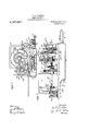
- Figure l is a plan view of a mining machine embodying my improvements
- Fig. 2 is a section on the line 22, Fig. 1
- Fig. 3 is a side elevation of the same with a por tion of the cutting apparatus broken away.
- Figs. 4c and 4 are enlarged sections on the line Fig. 1, showing the operatingmechanisms and the cutter frame respectively;
- Fig. 5 is an enlarged section on the line 5 5, Fig. 1;
- Fig. 6 IS an enlarged section on the line 66, Fig. 1;
- Fig. 7 is a side elevation, partly in section, of the guidingcable drums;
- Fig. 8 is an end elevation of said drums;
- FIG. 9 is a side elevation on a smal scale showing the method of leading the min ng machine upon a transporting truck;
- Fig. 10 is a plan view on a small scale showing the mining machine ar anged to feed transversely to the coal face at the beginning of a cut;
- Fig. 11 is a plan view on a small scale showing the mining machine and its operating parts arranged to feed laterally along the coal face;
- Fig. 12 is an edge view of the detachable pawl lever used in connection with the guiding-cable drums;
- Fig. 13 is a face View of a plate constituting part of the guiding-cable drum structure; and
- Fig. 14 is a plan View of the clutch lever used in connection with said cable drums.
- A indicates the bed frame as an entirety
- B the cutting apparatus extending from the inner end thereof and supported thereby
- C the feeding and guiding mechanism for advancing the cutting apparatus and machine either longitudinally or ,laterally
- D the motor mechanism and the auxiliary parts employed when it is desired to have a cutting apparatus advanced into the coal transversely to the face thereof.
- the main frame may be of any suitable construction, as far as some features of my invention are concerned, but, for reasons which will later appear, I prefer a con struction of the character construction comprises a plate-like shoe 1 adapted to rest upon the ground, and slide freely thereon in any direction, longitudinally arranged angle bars or plates, 2, 2 secured to said shoe at either side thereof and a suitable platform 3 resting upon and secured to said longitudinal side bars.
- r, 4.- are webs or plates depending from the platform 3 and carrying at their lower ends the outwardly turned longitudinally extending cutting apparatus guides 5, 5
- the main frame .thus constructed constitutes a box which is closed on all sides except the inner and outer ends.
- the platform 8 extends at its outer end beyond the bottom plate or shoe 1 and that the side plates 2 are correspondshown. This ingly cut away. In other words, the outer end of the upper platform part of the main frame overhangs considerably.
- the cutting apparatus comprises a longitudinally arranged horizontally disposed .base plate 6, two longitudinally arranged horizontally disposed guide plates 7, above said base plate and spaced therefrom by the longitudinally arranged bars 8 so as to form a chain guide or recess 9, the parts just referred to being secured together in any suitable manner, as by rivets 10.
- FIG. 11 is an inner sprocket wheel mounted upon a vertical axle 11', and between the inner end of the base plate 6 and a top plate 12 suitably secured to the base plate and having a rearwardly extending centrally arranged part 12 fitted snugly between the top bars 7, 7 of the chain frame.
- the motor D is suitably secured upon the platform 3 with its armature shaft 13 arranged longitudinally of the machine.
- 14 is a longitudinally arranged shaft, preferably having its axis in the vertical longitudinal plane of the axis of the chain frame. It is suitably mounted near either end in bearings 14' and 14', one of which is carried by a bearing standard l4 suitably secured to, the platform 3.
- the standard 14' extends transversely of the machine in either direction from the shaft 14 for the purposeto be hereinafter described.
- k is a vertically disposed shaft suitablymounted in bearings carried by the main frame of the machine and having its axis in the vertical plane containing the axis of the shaft 14.
- '20 is a bevel gear secured to the upper end of the said vertical shaft and in mesh with the bevel pinion 17 21 is a sprocket drive wheel rigidly secured to the lower end of the vertical shaft 19.
- cutter frame 22 indicates as an entirety an endless cutter chain or carrier extending around the sprocket drive wheel 21 and the inner ides 9 of the said cutter frame and carrymg laterally extendingrcutters 23 of any smtable construction.
- he cutter frame is supported from the main frame by the longitudinally arranged slides .or guides 5 depending from the main frame and arranged to fit snugly between the base plate and the upper plate of the chain frame.
- the main frame and the chain frame are normally held from longitudinal movement relative to each other by mechanism indicated as an entirety by 24, which also serves as an adjusting means for moving the frames relative to each other to vary the tension upon the cutter chain.
- the adjusting-mechanism 24 comprises a longitudinally arranged screw threaded shaft 24' mounted near its inner end in a bearing in a depending plate 25 which is secured to the inner end of the main frame platform 3. Near its outer end it is fitted into a threaded nut 26 which is arranged between uprights-or projections 27, 27 carried by the base plate 6.
- the inner end of this shaft is squared as indicated at 24 to receive a suitable wrench for turning the shaft in either direction so as to further extend the chain frame or to retract it relative to the main frame, as desired.
- 29 is a shaft arranged beneath the said shaft 14 and transversely of the main frame. It is suitably mounted in a bearing 29' secured'to the platform of the said frame.
- ' 30 is a worm wheel secured to one end of the ,said transverse shaft 29 and in mesh with the worm 28 on the shaft 14.
- clutc mechanism 36 indicates as an entirety clutch mechanism for alternately connecting the ears 34 and 35 to the shaft 32.
- clutc mechanism 36 indicates a longitudinally movable element s lined to the shaft 32 and carrying at one en clutch jaws 36 adapted to engage clutch jaws 36" secured to the gear wheel 35 and at its other end clutch jaws 36 adapted to engage with the clutch jaws 36 carried by the gear wheel 34.
- drum shaft 38 is a longitudinally arranged drum shaft suitably mounted near either end in bearings 38, 38, in the bearing standards 14 and 32 respectively.
- the axis of this shaft is on the opposite side of the vertical plane containing the axis of the shaft 14 from the axis of the shaft 32.
- the drum 41 it a cable winding drum loosely mounted on the shaft 38 and preferably adjacent to the gear wheel 40 at the inner end thereof.
- the periphery of the cable drum may be spirally grooved as indicated at 41 to assist in the spooling of a draft cable upon the drum.
- the drum is preferably connected to the shaft 38 by means of a friction clutch 41, one element of which is a ring or casing 41 carried by the drum and extending outwardly therefrom, and the other element of which is a pulley or ring 41" having its rim radially slotted at 41 41, as indicated.
- This pulley 43 is mounted in a swiveling support having a spindle mounted in a bracket hearing 43.
- the pulley spindle can be rotated so that the pulley can be bodily turned to permit it to lie in either of several planes.
- the pulley is at substantially right angles to the longitudinal lines of the machine.
- the pulley is turned inward as shown in Fig. 10.
- WVhen the machine is being loaded onto a truck, the pulley is turned to the opposite position, as shown in Fig. 9.
- the pulley support or carrier is so constructed as to hold the pulley axis in a plane other than the plane of the axis of the spindle part.
- the pulley carrier is similar to the fork carrier of the caster wheel.
- That at 56 passes around a sheave at 54 mounted ina bracket 55 at the inner end of the machine, thence outward to a sheave 53, at the outer corner of the machine and thence to the spool or winding drum 46.
- the cable 56 is at its rear end secured to an anchoring device, such as a jack at 57, and is wound upon a spool or drum at 47.
- the two spools or drums 46 and 47 are supported by a bracket indicated as an entirety by 49, having a base plate 49 which is secured to the outer corner of the machine frame. From the vertical plate of the bracket there projects outward a hearing cylinder 49*.
- a sleeve 50 Upon this there is fitted a sleeve 50, at the outer end of which there is a series of ratchet teeth 50.
- this sleeve Upon this sleeve, in turn, are fitted the two reels or drums 46 and 47.
- the inner reel or drum 46 after being slipped upon the cylinder 50 is rigidly secured thereto by keys or otherwise.
- the outer reel 47 is loose upon .the sleeve. It has a tubular part at 47 which provides a bearing support on the sleeve and short distance under the peripheral part of the reel or drum 46.
- ratchet wheel 50 On the outer side or face of the reel 47 there is formed a ratcheted flange 47 The reels are held in place on the sleeve 50 by a plate or disk 58 which is fastened to the end of the bearing-cylinder 49 When the parts are assembled the ratchet wheel 50 is situated in the chamber or space at 50, and just inside of the plate 58. In the annular chamber or space at 59 there is a pawl 60 pivoted to the ear 61 and adapted to engage with the teeth at 50, so as to pre vent relative rotation of the drums in one direction. It will be understood that pawl 60 is to be maintained in operative engagement with the ratchet in any suitable well known manner.
- a spring is provided to press the pawl into engagement with the ratchet teeth.
- the reel 47 is adapted to be rotated by a pawl 62 which can'be'mounted on the machine but which I prefer to have carried by a detachable lever handle such as shown at'63.
- a detachable lever handle such as shown at'63.
- To the face plate 58' are secured studs or fulcrum pins 64 and the lever 63 can be detachably connected with either of these at will.
- the pawl 62 is pivoted at such point that when the lever is in position it engages with one or the other of the teeth
- these devices are used to vary theposition of the machine relative to its lines of travel by varying the tension on the cable 56. In this case the adjustment of parts is effected by hand.
- Another mechanism is also illustrated by means of which this varying or adjusting of the machine can be accomplished y power.
- 's' dog 65 is a dog movably supported in the chamber in the interior of cylinder 49 and adapted to be advanced through an aperture 66 in the cylindrical periphery of the bearing and 'to engage one or the other of a I series of registering apertures 49 in the cylinder 50, 's' dog 65 is pivoted to'the lever 67 which is arranged to project through the slot 72 .in the face plate 58. "At the'inner end the lever is pivoted to a support in the metal at the inner end of the bearing 49". The lever 67 projects far enough beyond the outer end of the reels to permit the operator to push the dog 65 outward when he desires. As soon as this dog engages with the sleeve 50, the latter will be locked against rotation, and with it the inner reel 46.
- the reel 47 is locked atthe same time to the sleeve by means of the pawl '60 carried by the reel 47 and engaging the teeth at 50*. If at the timeof such locking together of the parts the machine is inoperation, the reels become -a stationary point rigidly connected to an anchoring device in the rear of the machineand to an anchormg device in the front. And as the reel or drum41 is exertmg a stress upon the cable 44, the front end "of the machine tends to advance while the rear end is held stationary and as a result the longitudinal line of the machine tends to assume a greater and'greater inclination to the line of travel of the machine along ---the face.- As soon as the machine has assumed the position of inclination desired,
- cables 44 and 56 are fastened stationarily and independently of each other at their front ends. Each may be secured -to a separate anchoring device or they may be independently fastened to a common ol r. Such as ew r ia r. n ther inserted into the coal.
- cut'must be made in order to get the cutting apparatus under the coal, this entefing' cut beingm e adjacent one or the'other of the ribs constitutingthe side walls 'of the room.
- lVith 'my improved -machine the sumping cut is made by feeding the machine longitudinally forward so as topro- .ject, the cutting apparatus into the coal.
- 74 is a guide, formed preferablyof an angle iron.
- This guide is designed to be placed on the floor of the mine with its length extending parallel to the direction in which the cutting apparatus is to be advanced into the coal. In the drawing it is shown approximately at right angles to the face of the coal. It is rigidly fastened in position to the floor-by means of a jack 75 at the outer end and adapted to reach'the roof, and a jack 76 at the inner end adapted to engage withthe face of the coal, and preferably situated at an angle to the face so as to overcome the tendency to lateral displacement under the stresses from the machine.
- The'side bars of the machine are provided with one or more guide irons these guiding devices which or clips 77 which overlap or engage loosely with the flange on the guide.
- the one clip 77 in the construction illustrated is designed to be substituted for the guide sheave 54, as will be seen from a comparison of F 1. 2 and 10.
- the machine is first put into the position shown in Fig. 10 with the cutting apparatus directed toward and approximately at right angles to the face to be undercut.
- the guide rail 74 is then put into position at the side of the machine and securedin place by the jacks 75 and 76.
- the cable sheave 43 is turned around so that the planes transverse to its axis are parallel to the longitudinal lines of the machine as shown in Fig. 10.
- the high speed gears might be employed to feed the machine to its work in case the coal is very soft, but ordinarily the low speed gears are used for this purpose, the high speed gears being reserved to drive the drum 41 when the propelling cable is used to drag the machine about from one position in the mine room to another.
- the clutches having been thrown into engagement as stated, the machine as an entirety is drawn endwise toward the coal and this motion continuing 'finally brings it to a position where the active part of its cutting apparatus is entirely under the coal and the frame and power parts are close to the face. Then the motor is temporarily stopped.
- the jacks 75 and 76 are loosened and they and the guide rail 74 are laid aside.
- the cable 44 is stretched across the room near the coal face and its free end is secured to the jack or anchoring device at 78.
- the cable 56 is passed around the guide sheaves 53 and 54 and extended along the face of the coal to the distant rib where its end is made fast adjacent the end of cable 44.
- the loose end of cable 56 is then secured to the adjacent anchor 57 and by means of the ratchet devices above described the tension of the two cables 56 and 56 is properly adjusted. Then the motor is again put into operation.
- the operator can cause the dog 65 to lock the sleeve against rotation, whereupon the reels and the adjacent parts of the cables become, in effect, a pivoting point for the machine, around which the inner part of it swings as the draft on the cable 44 continues.
- the machine can, when it is de sired, be angled in the opposite direction.
- the stress on pawl can be eased off so that the pawl can be disengaged to permit paying out of cable 56 under control of the hand lever 68.
- Such paying out of cable 56 permits the outer end of the machine to swing forward under the action of the draft in'cable 44, as will readily be understood. 4 I
- the retarding c'an'be increased up to the point of actual stoppage and, consequently, the angled the machine to the face of the coal canbe varied either, as above described,.'manually, or by 'the'f'or'ce of'the motor.
- the machine can readil be angled backward or forward by 'suit'ab e manipulation of the control devices associated with the cables 56 and 56 and their windingdrum's 46 and 47.
- v S' ce these control devices are 'all'mounted on t 0 machine, the guiding and angling operations which have beenreferred to can be effected with much greater ease and convenience than is possible with machines having devices associated with 'the anchored end of the guide cable for taking up or paying out said cable.
- Impuntres so hard are sometlmes encountered that it is possible to cut through them, if 'at all, only at a greatly reduced rate of feed.
- the friction clutch by which the winding drum 41 is driven is very advantageous. As soon as the resistance to therotationof the drum reaches'a'certa'm intensity the clutch permits slippage and thus prevents breakage of the machine parts. If the obstruction is not too harder too extensive it may be possible to cut through it at the slow rate permjttedby theslippage, the guide cables and associated devices "0 crating meantime in their usual manner ecause they are inde- I pendent fofthe prbpelling cable mechanism. cl "In any case the 'slippa'ge'of'theclutch gives mum 'the'machine runner ample warning of the obstruction without sub ecti'ng the machine tojimury.
- Jacks 75 and 7 6 and the holder 74 are laterally separable from the machine and are more or less independent thereof inasmuch as the clip 77 can readily be removed or not used at all. If, as the cutters advance into the coal the latter should present regions of hardness, the cutting apparatus may be deflected away from the line of the feed rope 44 shown in big. 10. And as the feeding and guiding devices, during the sumping action, are largely independent of the machine, the latter can take a more or less swerving path without interference.
- the present mechanism differs from those previously referred to which have had the frame and the cutting apparatus mounted in a box or pan-like structure made in one part or two parts and arranged to have the infeeding draft cable secured to the inner end of this box or pan.
- the inner jack 76 can be placed at either of several positions along the .coal face, at option, according to circumstances and the inpulling feed cable 44 can be secured thereto more or less independently of the position of the main frame; and there 11:
- the pulley-43 is moved around in the opposite direction and the forward end of the cable 4st is secured to a jack fastened at some suitable point in front of the truck. Power being applied to the winding drum 41 the stress exerted upon the cable results in drawing the machine toward the jack which continues until it is free of the truck.
- 'Ihis'mechanism comprises a transversely arranged shaft 68 in axial alinement with the transverse shaft 29, the inside end of which latter shaft is fitted into a recess '68 in the inside end of the shaft 68.
- 69 is a positive clutch, one element of which 69 is secured to the shaft 29 and the other element 69 is carried by the inside end of the shaft 68.
- the shaft 68 is suitably supported on a bearing 70 secured to the main frame.
- the shaft 71 is a sprocket wheel rigidly se-' cured to theoutside end of the shaft 68 and adapted to be connected with the propelling mechanism on the mining machine truck. ⁇ Vhen not required in use the shaft 68 may be removed from the machine by drawing it longitudinally out from the bearing 70.
- a third cable adapted to extendfrom the outer end of the machine to a stationary holder at the rear thereof and having its forward end connected to the said second cable through the last named winding reel and arranged to have its operative part lengthened while the operative part of the said second cable is being shortened, substantially as set forth.
- a second cable section operatively connected to the last named winding reel and extending from the outer part of the frame to a rear holder, said cable sections being adapted to sustain drafts in opposite directions, and means for tightening the rear section relatively to the front section.
- the combination of the frame, the cutting apparatus carried thereby, the propelling mechanism on the frame, and means for guiding the machine in its movement along the face of the coal comprising two cable sections, two reels for the said sections respectively, means adapted to operatively connect said two reels, one of the cable sections extending forward from the inner part of the machine and the other extending backward from the outer part thereof, means for locking one of said reels against rotation, and manually controlled means for turning one of said reels in relation to the other.
- the comblnatlon of the frame, the cutting apparatus carried' thereby, the propelling mechanism on the frame, and means for guiding the machine in its movement along the face of the coal comprising two cable sections, two reels for the said sections respectively, means adapted to operatively connect said two reels, one of the cable sections extending forward from the inner part of the machine and the other extending backward from the outer part thereof, means for locking said reels against rotation, and means for turning one of said reels in relation to the other.
- a frame, cutting apparatus extending therefrom, means for propelling the machine along the face of the coal, and means for guiding the machine comprising a cable section extending from the inner part of the machine to a stationary holder in advance thereof, a second cable section extending from the outer part of the machine to a stationary holder on the rear side thereof, and means mounted on the machine for positively engaging the cable sections and operating when the machine is moved forward to pay out one cable section as the other is drawn in.
- a frame, cutting apparatus extending therefrom, means for propelling the machine along the face of the coal, and means for guiding the machine comprising a cable section extending from the outer part of the frame to a stationary holder on the rear side of the machine, a windin drum on which said cable is wound an adapted by its rotation to pay the cable out as the machine advances-along; the face of the coal, means for retarding such rotation of the winding drum, and means controllable atwill for stopping the paying'out of the cable to cause the propelling mechanism to swing the machine and change its working angle to the coal face.
- a frame In a mining machine, the combination of a frame, cutting apparatus extending therefrom, a driving motor on the frame, draft mechanism operatin on the inner part of the machine to a vance it along the face of the coal to be cut, means independentjfofssaid draft mechanism for retarding theouter part of the frame, said which is a retarding means operating automatically to hold the machinein alinement as it is advanced by the draft mechanism, and means controllable at will for causing the power of the motor to swing the machine and chalnge its working angle to the-face of the coa 26.
- a frame In a mining machine, the combination of a frame, cutting apparatus extending from the inner end of the frame, a driving motor on the frame, draft mechanism acting on the inner part of the frame to propel the machine along the face of the coal to be undercut, means operable independently of said draft propelling mechanism for retarding the outer end of the machine, and
- a mining machine the combination of a frame, cutting apparatus extending therefrom, a driving motor on the frame, draft mechanism operating on the inner part of the machine to advance it along the face of the coal to be cut, means independent of said draft mechanism for retarding the outer part of the frame, said retarding means operating automatically to hold the machine in alinement as it is advanced by the draft mechanism, and manual devices on themachine adapted in cooperation with the retarding means to swing the machine and change its working angle to the coal face.
- a frame a cutting apparatus extending from the inner end thereof, draft devices operating to advance the machine, flexible bottom support below the power frame consisting of a shoe-like or runner-like plate adapted to rest directly upon the mine floor and to move universally thereon, a winding mechanism driven by the said motor, a cable having its end secured to the winding mechanism to be positively wrapped thereon and extending from the inner part of the power frame along the face of the coal to be cut to a stationary holder, a second independent supplemental cable extending rearward from the outer end of the power frame to a holder, a winding drum upon which the said second cable is wound, and which is adapted by its rotation to pay out the said cable as the machine advances along the face of the coal,
- drum substantially as set forth 32.
- a frame cutting apparatus extending inward therefrom, means for propelling the machine along the face of the coal, a shoelike ground support for the frame upon which it is 'movable universally on the ground, and means independent of the propelling meansfor guiding the machine comprising a cable section extending rearward from the outer part of the frame and adapted to have one end part secured to a stationary holder at the rear, means 'on the machine adapted to yieldingly hold the other end part of the cable and to permit the lengthening of its rearward extending portion at a rate equal to or differing from the rate of forward feed of the front part'of the machine, and means for changing at will the rate at which said guiding cable is lengthened.
- a main frame having a bottom part adapted in operation to rest directly on and slide over the mine floor, a cutter frame rigid with the main frame and projecting from the inner end thereof, an endless cutter chain mounted on the cutter frame, propelling means adapted to bodily slide the machine endwise on the mine floor transversely to the coal face to initially advance the cutters under the coal, and means for guiding the machine in its endwise movement adapted to be fixed in position on the mine floor at one side of the main frame of the machine and to slidably engage said main frame.
- a main frame having a bottom part adapted in operation to'rest directly on and slide over the mine and means for guiding the machine in its endwise movement comprising an elongated guide rail adaptedto be fixed in position on the mine floor at one side of the main frame and to slidably engage said main frame.
- a main frame having a bottom part adapted in operation to rest directly on and slide over the mine floor, a cutting frame rigid with the main frame and projecting from the inner end thereof, an endless cutter chain mounted on the cutter frame, propelling means adapted to bodily slide the machine endwise on the mine floor transversely to the coal face to initially advance the cutters under the coal,
- the mine floor at one side of the main frame of the machine and to slidably engage said frame, and means adapted to maintain the side of the machine frame in sliding engagement with the guide rail whilethe machine is advanced toward the coal face.
- a main frame extending from the inner end thereof, means for propelling the frame and cutting apparatus bodily along the coal
- a guiding or al ning mechanism comprising a tension device independent of the aforesaid propellmg means and adapted to extend from the outer part of the main frame to a stationary holder on the rear side of the machine, a rotary device for carrying and automatically paying out the said tension device as the machine advances along the coal, and means for controlling the rate of rotation of the rotary device.
- a guiding'and alining mechanism comprising a, tension device independent of the aforesaid propelling means andadapted to extend from the outer part of the main frame to a stationary holder on the rear side of the machine and a rotary device for carrying and automatically paying out the said tension device as the machine advances along the coal.
- a main frame power-driven cutting apparatus projecting from the inner end thereof, power devices for feeding the machine along the face of the coal, and means for retarding the outer end of the machine comprising a cable adapted to be connected to an anchor at the rear side of the machine, and means independent of the aforesaid power feeding devices for paying out the cable, said means being connected to the cable and adapted to automatically resist the lengthening of the rearward extending part thereof.
- a mining machine having in combination a frame, cutting devices extending from the inner end of the frame, feeding'devices arranged to exert a forward propelling force on the frame, and retarding means arranged to exert an o posing force on the machine on a line 0 set from that of the forward force, said retarding means comprising a flexible device, a rotatable winding device for paying out the flexible device as the machine advances along the coalface, and means under manual control for retarding the rotation of the said rotatable winding device.
- manually controlled means associated with the last namedcable for causing .it to hold the machine at either of several angles to the face of the coal while it is being normally propelled by'the'other aforesaid cable.
- a main frame cutting apparatus extending from the inner end thereof, a winding reel on the frame, a cable secured at one end to said reel and adapted to have its other end fastened to a stationary holder in advance of the machine to propel it along the coal face, means for retarding the outer end of the frame comprising a cable indenormally pro- "pendent of the said propelling cable, and
- a propelling cable having one end secured to said reel and its other end adapted to be secured to a stationary holder in advance of the machine so as to exert a forward draft on the inner end of the main frame
- a second reel mounted on the main frame
- a retarding cable having one end secured to said reel and its other end adapted to be secured, to a stationary holder in the rear of the machine so as to exert a rearward draft on the outer end of the machine
- power devices for driving the first named reel to propel the machine forward and means on the machine frame for variably controlling the rotation of the second named reel to pay out the retarding cable as the machine advances.
- a main frame projecting from the inner end thereof, devices for feeding the machine along the face of the coal, and means for retarding the outer end of the machine comprising a cable, an anchor arranged at the rear side of the machine to take the draft of said cable, and means independent of the said feeding devices for paying out the ca ble, the last said means being mounted on the machine and adapted to automatically resist the lengthening of the rearward extending part of said cable.
- winding means for retarding the outer end of the machine comprising a cable, an anchor arranged at the rear side of the machine to take the draft of said cable, and means carried by the mahine and independent of. the said feeding devices for paying out the retarding cable,
- said cable having the end part which is adacent the machine movably secured to said paying out means.
- a main frame In a mining machine of the class set forth, the combination of a main frame, cutting apparatus projecting from the inner end of said main frame, devices for feeding the machine along the face of the coal, and means ada ted to retard the outer part of the main rame comprising a cable, an anchor arranged at the rear side of the machine to sustain the draft of said cable, and means carried by the machine independent of said feeding devices arranged to cooperate with the cable to effect, the paying out of the cable under manual control.
- a main frame, cutting, apparatus projecting from the inner end of said frame devices for feeding the machine along the face of the ,-coal comprising a winding reel and a cable having one end fixed to the winding reel and its other end adapted to be secured to a stationary holder, a retarding cable separate from the feed cable and adapted to have one end secured I to" -a- "stationary holder, and means carridbythe machine arranged to 006perate with the retarding cable to effect the paying out thereof under manual control, the force of the retarding cable acting upon the machine frame at a point nearer the outer end thereof than does the forward propelling force of the feed cable.
Landscapes
- Engineering & Computer Science (AREA)
- Mining & Mineral Resources (AREA)
- Mechanical Engineering (AREA)
- Life Sciences & Earth Sciences (AREA)
- General Life Sciences & Earth Sciences (AREA)
- Geochemistry & Mineralogy (AREA)
- Geology (AREA)
- Storing, Repeated Paying-Out, And Re-Storing Of Elongated Articles (AREA)
Description
W. P. TROTTER.
MINING MACHINE.
APPLICATION FILED SEPT. 10,1907
Patented Feb. 9, 1915.
6 SHEETS-SHEET l.
XMMN m moemtoz QR f u moses W. F. TROTTER.
MINING MACHINE.
APPLICATION FILED SEPT. 10,1907.
Patented Feb. 9, 1915.
6 SHEETS-$151131 2.
. N 1. @WNNMM wvxhweklm p q vitmeooeo W. F. TROTTER.
MINING MACHINE.
APPLICATION FILED SEPT. 10,1907.
1,127,6?. Patented Feb. 9, 1915.
W g I @HOMIZ W. F. TROTTER.
MINING MACHINE.
APPLIOATION FILED SEPT.10,1907.
Patented Feb. 9, 1915.
6 SHEETS- vi. w!
W. F. TROTTER.
MINING MACHINE.
APPLIOATION FILED SBPT.10,1907.
6 SHEETS-SHEET 5.
Patented .Feb. 9, 1915.
Witwwom W. F. TROTTER.
MINING MACHINE.
APPLICATION FILED. SEPT. 10,1907.
Patented Feb.9,1%23.
e SHEETS-SHEET 6 WALTER F. TROT'I'ER, OF CHARLESTON, WEST VIRGINIA, ASSIGNOR, BY MESN E AS SIGN- MENTS, TO THE JEFFREY MANUFACTURING COMPANY, A CORPORATION OF OHIO.
MIN ING-MA CHINE.
Specification of Letters Patent.
Patented Feb. 9, 1915.
Application filed September 10. 1907. Serial No. 392,164.
To all zrlzom. it may concern:
lie it known that I, lVALrER F. Tno'i'rnn, a citizen of the United States, residing at Charleston, in the county of Kanawha and State of West Virginia, have invented certain new and useful Improvements in Mining-Machines, of which the following is a specification, reference being had therein to the accompanying drawing.
This invention relates to improvements in mining machines, particularly to side cutting mining machines. It has been proposed heretofore to provide machines of this class with flexible draft devices adapted to propel the machine along the face of the coal and to guide it or hold it to its work. In some cases cables were to be used as the flexible draft and holding members, and in other cases the functions ofpropelling and guiding the machine were to be performed by chains in connection with sprocket mechanisms or the like on the machines adapted to engage positively and rigidly with the chains. In one forln of these latter machines, for example, a single continuous chainis provided having one end fixed to an anchor or the like in advance of the machine and its other end fixed to'an anchoring device on the rear side of the machine. while intermediate its ends the chain passes over sprocket drive mechanisms on the machine.
My invention contemplates the use preferably of cables for propelling and guiding the machine and is intended'to provide a machine in which are overcome certain disadvantages and dliliculties that have heretofore been experienced in the use of side cutting machines, especially in propelling and guiding the machines in room and pillar mining.
The nature and all of the various objects of the invention will be understood in detail from the following description in connection with the drawings.
Figure l is a plan view of a mining machine embodying my improvements; Fig. 2 is a section on the line 22, Fig. 1; Fig. 3 is a side elevation of the same with a por tion of the cutting apparatus broken away. Figs. 4c and 4 are enlarged sections on the line Fig. 1, showing the operatingmechanisms and the cutter frame respectively; Fig. 5 is an enlarged section on the line 5 5, Fig. 1; Fig. 6 IS an enlarged section on the line 66, Fig. 1; Fig. 7 is a side elevation, partly in section, of the guidingcable drums; Fig. 8 is an end elevation of said drums; Fig. 9 is a side elevation on a smal scale showing the method of leading the min ng machine upon a transporting truck; Fig. 10 is a plan view on a small scale showing the mining machine ar anged to feed transversely to the coal face at the beginning of a cut; Fig. 11 is a plan view on a small scale showing the mining machine and its operating parts arranged to feed laterally along the coal face; Fig. 12 is an edge view of the detachable pawl lever used in connection with the guiding-cable drums; Fig. 13 is a face View of a plate constituting part of the guiding-cable drum structure; and Fig. 14 is a plan View of the clutch lever used in connection with said cable drums.
For the purposes of illustration I have shown in the drawing a mining machine of which A indicates the bed frame as an entirety, B the cutting apparatus extending from the inner end thereof and supported thereby, C, C the feeding and guiding mechanism for advancing the cutting apparatus and machine either longitudinally or ,laterally, D the motor mechanism and the auxiliary parts employed when it is desired to have a cutting apparatus advanced into the coal transversely to the face thereof.
The main frame may be of any suitable construction, as far as some features of my invention are concerned, but, for reasons which will later appear, I prefer a con struction of the character construction comprises a plate-like shoe 1 adapted to rest upon the ground, and slide freely thereon in any direction, longitudinally arranged angle bars or plates, 2, 2 secured to said shoe at either side thereof and a suitable platform 3 resting upon and secured to said longitudinal side bars.
r, 4.- are webs or plates depending from the platform 3 and carrying at their lower ends the outwardly turned longitudinally extending cutting apparatus guides 5, 5
The main frame .thus constructed constitutes a box which is closed on all sides except the inner and outer ends.
It will be observed on reference to Figs 3 and 4 that the platform 8 extends at its outer end beyond the bottom plate or shoe 1 and that the side plates 2 are correspondshown. This ingly cut away. In other words, the outer end of the upper platform part of the main frame overhangs considerably.
The cutting apparatus comprises a longitudinally arranged horizontally disposed .base plate 6, two longitudinally arranged horizontally disposed guide plates 7, above said base plate and spaced therefrom by the longitudinally arranged bars 8 so as to form a chain guide or recess 9, the parts just referred to being secured together in any suitable manner, as by rivets 10.
11 is an inner sprocket wheel mounted upon a vertical axle 11', and between the inner end of the base plate 6 and a top plate 12 suitably secured to the base plate and having a rearwardly extending centrally arranged part 12 fitted snugly between the top bars 7, 7 of the chain frame.
The motor D is suitably secured upon the platform 3 with its armature shaft 13 arranged longitudinally of the machine. 14 is a longitudinally arranged shaft, preferably having its axis in the vertical longitudinal plane of the axis of the chain frame. It is suitably mounted near either end in bearings 14' and 14', one of which is carried by a bearing standard l4 suitably secured to, the platform 3. The standard 14' extends transversely of the machine in either direction from the shaft 14 for the purposeto be hereinafter described.
15 is a spur gear rigidly secured to the shaft 14 and meshing with a pinion 16 secured to the inner end of the armature shaft 13.
ing the element 18 of the clutch in either disprocket 11 carried by the cutter frame, it
being arranged at either side within the 17 is a bevel inion loosely mountedon the shaft 14 near t e outer end thereof.
18 indicates a positive clutch interposed between the said shaft 14, and the bevel pinion 17, the longitudinally stationary element 18' of said clutch being secured to the said bevel pinion and the longitudinally movable element 18 being spline to the shaft.
18 indicates suitable mechanism for movrection.
19 is a vertically disposed shaft suitablymounted in bearings carried by the main frame of the machine and having its axis in the vertical plane containing the axis of the shaft 14. '20 is a bevel gear secured to the upper end of the said vertical shaft and in mesh with the bevel pinion 17 21 is a sprocket drive wheel rigidly secured to the lower end of the vertical shaft 19. k
22 indicates as an entirety an endless cutter chain or carrier extending around the sprocket drive wheel 21 and the inner ides 9 of the said cutter frame and carrymg laterally extendingrcutters 23 of any smtable construction. he cutter frame is supported from the main frame by the longitudinally arranged slides .or guides 5 depending from the main frame and arranged to fit snugly between the base plate and the upper plate of the chain frame. The main frame and the chain frame are normally held from longitudinal movement relative to each other by mechanism indicated as an entirety by 24, which also serves as an adjusting means for moving the frames relative to each other to vary the tension upon the cutter chain. The adjusting-mechanism 24 comprises a longitudinally arranged screw threaded shaft 24' mounted near its inner end in a bearing in a depending plate 25 which is secured to the inner end of the main frame platform 3. Near its outer end it is fitted into a threaded nut 26 which is arranged between uprights-or projections 27, 27 carried by the base plate 6. The inner end of this shaft is squared as indicated at 24 to receive a suitable wrench for turning the shaft in either direction so as to further extend the chain frame or to retract it relative to the main frame, as desired.
28 is a worm gear rigidly secured to the longitudinally arranged shaft 14 near the inner end thereof and betweenthe bearing standard 14 and the gear wheel 15 secured to the said shaft.
29 is a shaft arranged beneath the said shaft 14 and transversely of the main frame. It is suitably mounted in a bearing 29' secured'to the platform of the said frame.
' 30 is a worm wheel secured to one end of the ,said transverse shaft 29 and in mesh with the worm 28 on the shaft 14.
31 is a worm rigidly secured to the other end of the shaft 29.
32 is a longitudinally arranged shaft mounted near either end in bearings 32', 32', carried by bearing standards 14 and 32, the latter being arranged parallel to the former and of substantially the same width and secured to the platform of the main frame. The axis of this shaft 32 is in a vertical longitudinal plane on the opposite side of the vertical longitudinal plane of the ax s of the shaft 14 from armature shaft 13.
33 is a worm wheel rigidly secured to the outer end of the shaft 3; and in mesh with the worm 31 on the transverse shaft 29.
34 is a spur gear loosely mounted upon the shaft 32 adjacent to the bearing standard 14, and 35 is a gear wheel of greater di ameter than the gear wheel 34 and loosely' mounted upon the said shaft 32 adjacent to the bearing standard 32.
36 indicates as an entirety clutch mechanism for alternately connecting the ears 34 and 35 to the shaft 32. Of this clutc mechanism 36 indicates a longitudinally movable element s lined to the shaft 32 and carrying at one en clutch jaws 36 adapted to engage clutch jaws 36" secured to the gear wheel 35 and at its other end clutch jaws 36 adapted to engage with the clutch jaws 36 carried by the gear wheel 34.
37 indicates as an entirety suitable mechanism for shifting the movable element 36' of the clutch in either direction at will.
38 is a longitudinally arranged drum shaft suitably mounted near either end in bearings 38, 38, in the bearing standards 14 and 32 respectively. The axis of this shaft is on the opposite side of the vertical plane containing the axis of the shaft 14 from the axis of the shaft 32.
39 is a gear wheel rigidly secured to the shaft 38 near one ,end thereof and in mesh with thegear wheel 34 on'the shaft 32, and 40 is a gear wheel of smaller diameter than the gear wheel 39 and rigidly secured near the opposite end of the shaft 38 and in mesh with the gear wheel 35 on the shaft 32.
41 it a cable winding drum loosely mounted on the shaft 38 and preferably adjacent to the gear wheel 40 at the inner end thereof. The periphery of the cable drum may be spirally grooved as indicated at 41 to assist in the spooling of a draft cable upon the drum. The drum is preferably connected to the shaft 38 by means of a friction clutch 41, one element of which is a ring or casing 41 carried by the drum and extending outwardly therefrom, and the other element of which is a pulley or ring 41" having its rim radially slotted at 41 41, as indicated.
41 are adjustable wedges or expan ders arranged between the sections of the rinr at said slots and adapted to force the periphery of the rim into engagement with the inner walls of the ring 41 in the well known manner. By varying the adjustment of the expanders the clutch can be made to slip when the resistance to the rotation of the winding drum reaches any given amount.
43 1s a pulley or sheave arranged to receive and guide the cable 44 as it is wound.
upon or is paid out from the drum 41. This pulley 43 is mounted in a swiveling support having a spindle mounted in a bracket hearing 43. The pulley spindle can be rotated so that the pulley can be bodily turned to permit it to lie in either of several planes. hen the machine is in operation and is being bodily advanced along the coal, the pulley is at substantially right angles to the longitudinal lines of the machine. When the machine is being advanced longitudinally to feed its cutting apparatus into the coal the pulley is turned inward as shown in Fig. 10. WVhen the machine is being loaded onto a truck, the pulley is turned to the opposite position, as shown in Fig. 9. In order to haveit automatically assume the most advantageous position, when stress is which extends a being exerted upon the cable, the pulley support or carrier is so constructed as to hold the pulley axis in a plane other than the plane of the axis of the spindle part. In other words, the pulley carrier is similar to the fork carrier of the caster wheel.
When the machine is in operation it is advanced along the face of the coal by tension in the draft cable 44 due to the rotation of the drum 41. Under the action of this forward draft, the outer end of the machine tends to swing forward relative to the cutter frame because of the resistance which the coal offers to the advance of the cutters. To overcome this tendency and maintain the machine in proper working position relative to the face of the coal, I use a cable or cables supplemental to the main draft cable for the purpose of guiding it. Preferably there are two supplemental cables for this purpose. One is indicated. at 56 and the other at 56. That at 56 passes around a sheave at 54 mounted ina bracket 55 at the inner end of the machine, thence outward to a sheave 53, at the outer corner of the machine and thence to the spool or winding drum 46. The cable 56 is at its rear end secured to an anchoring device, such as a jack at 57, and is wound upon a spool or drum at 47. The two spools or drums 46 and 47 are supported by a bracket indicated as an entirety by 49, having a base plate 49 which is secured to the outer corner of the machine frame. From the vertical plate of the bracket there projects outward a hearing cylinder 49*. Upon this there is fitted a sleeve 50, at the outer end of which there is a series of ratchet teeth 50. Upon this sleeve, in turn, are fitted the two reels or drums 46 and 47. The inner reel or drum 46, after being slipped upon the cylinder 50 is rigidly secured thereto by keys or otherwise. The outer reel 47 is loose upon .the sleeve. It has a tubular part at 47 which provides a bearing support on the sleeve and short distance under the peripheral part of the reel or drum 46. On the outer side or face of the reel 47 there is formed a ratcheted flange 47 The reels are held in place on the sleeve 50 by a plate or disk 58 which is fastened to the end of the bearing-cylinder 49 When the parts are assembled the ratchet wheel 50 is situated in the chamber or space at 50, and just inside of the plate 58. In the annular chamber or space at 59 there is a pawl 60 pivoted to the ear 61 and adapted to engage with the teeth at 50, so as to pre vent relative rotation of the drums in one direction. It will be understood that pawl 60 is to be maintained in operative engagement with the ratchet in any suitable well known manner. Commonly, in pawl and ratchet mechanism, a spring is provided to press the pawl into engagement with the ratchet teeth. The reel 47 is adapted to be rotated by a pawl 62 which can'be'mounted on the machine but which I prefer to have carried by a detachable lever handle such as shown at'63. To the face plate 58' are secured studs or fulcrum pins 64 and the lever 63 can be detachably connected with either of these at will. The pawl 62is pivoted at such point that when the lever is in position it engages with one or the other of the teeth And as will be explained, these devices are used to vary theposition of the machine relative to its lines of travel by varying the tension on the cable 56. In this case the adjustment of parts is effected by hand. Another mechanism is also illustrated by means of which this varying or adjusting of the machine can be accomplished y power.
65 is a dog movably supported in the chamber in the interior of cylinder 49 and adapted to be advanced through an aperture 66 in the cylindrical periphery of the bearing and 'to engage one or the other of a I series of registering apertures 49 in the cylinder 50, 's' dog 65 is pivoted to'the lever 67 which is arranged to project through the slot 72 .in the face plate 58. "At the'inner end the lever is pivoted to a support in the metal at the inner end of the bearing 49". The lever 67 projects far enough beyond the outer end of the reels to permit the operator to push the dog 65 outward when he desires. As soon as this dog engages with the sleeve 50, the latter will be locked against rotation, and with it the inner reel 46. The reel 47 is locked atthe same time to the sleeve by means of the pawl '60 carried by the reel 47 and engaging the teeth at 50*. If at the timeof such locking together of the parts the machine is inoperation, the reels become -a stationary point rigidly connected to an anchoring device in the rear of the machineand to an anchormg device in the front. And as the reel or drum41 is exertmg a stress upon the cable 44, the front end "of the machine tends to advance while the rear end is held stationary and as a result the longitudinal line of the machine tends to assume a greater and'greater inclination to the line of travel of the machine along ---the face.- As soon as the machine has assumed the position of inclination desired,
the operator withdraws the dog from the sleeve 50 after which the reels 46 and 4'? are free to again rotate, one for taking up its cable and theother for paying its cable out.
In the resent case-themechanism and the mode of operation difierfrom those set forth in my early application with respect to the fastenings or anchoring of the cable. In
this case the cables 44 and 56 are fastened stationarily and independently of each other at their front ends. Each may be secured -to a separate anchoring device or they may be independently fastened to a common ol r. Such as ew r ia r. n ther inserted into the coal.
cut'must be made in order to get the cutting apparatus under the coal, this entefing' cut beingm e adjacent one or the'other of the ribs constitutingthe side walls 'of the room. lVith 'my improved -machine the sumping cut is made by feeding the machine longitudinally forward so as topro- .ject, the cutting apparatus into the coal.
The side cutting machine heretofore proposed for room and pillar work have been open to serious objection in connection with the making of the sumping cut. Either there was no adequate provision for effecting the sumping cut, or, in the case of other machines, this entering but could be effected only by the use of a large, heavy and cumbersome frame or pan designed to support the entire machine and guide it while it was forced endwise toward the coal face in much the same manner as the main frame of a f breast machine supports and guides its cutter frame and carriage. It has been my purpose to avoid the use of the heav and cumbersome supporting and guiding rame, and I have accordingly designed the .main frame of my machine to work directly on the floor of the mine, and have provided.
guide devices for the machine which, while thoroughly effective, are light and easily handled.
Referring to Fig. 10, 74 is a guide, formed preferablyof an angle iron. This guide is designed to be placed on the floor of the mine with its length extending parallel to the direction in which the cutting apparatus is to be advanced into the coal. In the drawing it is shown approximately at right angles to the face of the coal. It is rigidly fastened in position to the floor-by means of a jack 75 at the outer end and adapted to reach'the roof, and a jack 76 at the inner end adapted to engage withthe face of the coal, and preferably situated at an angle to the face so as to overcome the tendency to lateral displacement under the stresses from the machine. The'side bars of the machine are provided with one or more guide irons these guiding devices which or clips 77 which overlap or engage loosely with the flange on the guide. The one clip 77 in the construction illustrated is designed to be substituted for the guide sheave 54, as will be seen from a comparison of F 1. 2 and 10. When the machine is being fed into the coal. its travel is governed by are subsequently removed.
The mode of operation of the above described mechanism will be fully understood. Assuming that it is desired to undercut the face of the coal in a room in a mine which is operated on the room and pillar plan, the machine is first put into the position shown in Fig. 10 with the cutting apparatus directed toward and approximately at right angles to the face to be undercut. The guide rail 74 is then put into position at the side of the machine and securedin place by the jacks 75 and 76. The cable sheave 43 is turned around so that the planes transverse to its axis are parallel to the longitudinal lines of the machine as shown in Fig. 10.
' The end of the cable 44 is then secured to the inner jack 76 or a suitable anchoring device, the cables 56 and 56 being now out of action, and preferably both wound up on their 7 respective drums 46 and 47 so as not to in terfere with the free handling of the machine. Current being introduced to the motor it is set in operation and drives the shafting and gearing down to and including the clutch element at 1. 8 and also the clutch element at 36. The operator upon shifting these drive clutch elements into engagement with their companion parts causes the power to be transmitted first to the cutting apparatus and secondly to the winding drum, the latter beingdriven preferably through the slow speed gears by throwing the clutch parts 36 and 36 into operative engagement. The high speed gears might be employed to feed the machine to its work in case the coal is very soft, but ordinarily the low speed gears are used for this purpose, the high speed gears being reserved to drive the drum 41 when the propelling cable is used to drag the machine about from one position in the mine room to another. The clutches having been thrown into engagement as stated, the machine as an entirety is drawn endwise toward the coal and this motion continuing 'finally brings it to a position where the active part of its cutting apparatus is entirely under the coal and the frame and power parts are close to the face. Then the motor is temporarily stopped. The jacks 75 and 76 are loosened and they and the guide rail 74 are laid aside. Thereafter the cable 44 is stretched across the room near the coal face and its free end is secured to the jack or anchoring device at 78. Next the cable 56 is passed around the guide sheaves 53 and 54 and extended along the face of the coal to the distant rib where its end is made fast adjacent the end of cable 44. The loose end of cable 56 is then secured to the adjacent anchor 57 and by means of the ratchet devices above described the tension of the two cables 56 and 56 is properly adjusted. Then the motor is again put into operation. The
If at any time during this undercutting operating it becomes necessary either because of a variation in the character of the coal, or because of the configuration of the face of the coal or of the floor of the mine, or for other reason, to vary the angular position of the machine, it can be quickly and easily done by means of the devices provided. The operator can with the lever 63 and pawl 62,impart one or more rotary steps to the reel 47 in the direction to wind up cable 56. This causes a relative shortening of the cable 56 and results in holding back the rear part of the machine in relation to the forward part. In this way, the machine can be inclined forward from its outer end relative to its path of advance if such positioning is desired. Or the same result can be obtained byutilizing power in the Way above described. That is to say, the operator can cause the dog 65 to lock the sleeve against rotation, whereupon the reels and the adjacent parts of the cables become, in effect, a pivoting point for the machine, around which the inner part of it swings as the draft on the cable 44 continues. On the other hand the machine can, when it is de sired, be angled in the opposite direction. By means of the lever 63 the stress on pawl can be eased off so that the pawl can be disengaged to permit paying out of cable 56 under control of the hand lever 68. Such paying out of cable 56 permits the outer end of the machine to swing forward under the action of the draft in'cable 44, as will readily be understood. 4 I
The rotation of the drum 47 is resisted or retarded by the cable section 56 and the drum 46 upon which it is wound in a direction opposite to the windin of the cable section 56 on the drum 47. en the parts of'the a paratus are so adjusted as to permit the ruins 46 and '47 to rotate with equal s eed the rtardationof the outer end of t e machine will be constant and proportioned to the winding up of the cable 56 and the unwinding of the cable 56, But, by means of the control devices above described, there can be variation in respect to i this matter of retarding "the outer endof ing movement of the machine can'be eifected periodically first in one direction, then m .the'1hachine. That is to say, the retarding c'an'be increased up to the point of actual stoppage and, consequently, the angled the machine to the face of the coal canbe varied either, as above described,.'manually, or by 'the'f'or'ce of'the motor.
Thus it -will be seen that the machine can readil be angled backward or forward by 'suit'ab e manipulation of the control devices associated with the cables 56 and 56 and their windingdrum's 46 and 47. v S' ce these control devices are 'all'mounted on t 0 machine, the guiding and angling operations which have beenreferred to can be effected with much greater ease and convenience than is possible with machines having devices associated with 'the anchored end of the guide cable for taking up or paying out said cable. With this latter arrangement itis necessary for the machine runner, whenever he desires to change the angle of the machine, to go from the machine back to the anchor at the rib, and when the room is thirty or forty 'feet wide much time is lost 'in'this way.
When it is desirable to do so,'the swing the other, so that the machine is given an oscillatory movement as itjadvances along the face. Such ah'andling of the machine is some imes advantageous when the coal carries impurities in the form of'hardnodules, "since 'the oscillatory movement, by
changing the lineo'f attack of the cutters,
tends to loosen'suchimpur'ities.
Impuntres so hard are sometlmes encountered that it is possible to cut through them, if 'at all, only at a greatly reduced rate of feed. In such cases the friction clutch by which the winding drum 41 is driven is very advantageous. As soon as the resistance to therotationof the drum reaches'a'certa'm intensity the clutch permits slippage and thus prevents breakage of the machine parts. If the obstruction is not too harder too extensive it may be possible to cut through it at the slow rate permjttedby theslippage, the guide cables and associated devices "0 crating meantime in their usual manner ecause they are inde- I pendent fofthe prbpelling cable mechanism. cl "In any case the 'slippa'ge'of'theclutch gives mum 'the'machine runner ample warning of the obstruction without sub ecti'ng the machine tojimury.
It will be understood, of course, that the oscillatory movement of the machine and the swingin thereof under manual control are possible bvreason of the fact that the main frame of the machine rests upon and is freely slidable upon the floor of the mine.
This'freedom of the machine for horizontal the floor of the mine makes possiblenot only angular or swinging movements, such as have been'referredt'o, but also bodily move-.
ments'of the'machine outward from and inward toward the coal facemovements ,which would of course be quite impossible if the machine were operated upon a track. 1
Thus, if the cutters, while making a cross undercut, encounter a very hard'obstacle of substantial dimensions, for example, a roll or "a large sulfur ball, which is bound'to lie in the'inner part of the cut,'thef machine can bestdpped and'jacks placed against the inner sides of the feed cable and the guide cable '56. Then, when the machine'is start- :ed'ag'aiia'the tension in the cables will draw the machine outward awayffrom the face as it advances, untilthe inner end'of the cutter bar clears the obstruction and, the'cut hav- 'ing "continued past the obstruction and the supplemental jacks having been removed, or preferably suitably placed against the outer sides of the babies, the machine is fed inward again toward'the face and the undercut continued at full depth. Such a procedure as this is greatly facilitated because 'of the possibilityof readily taking up or paying out either or both of the guide cables 56 and 56 so that the supplemental 'jacks'referred to can be effectively placed to force the machine outward from or inward toward the face of the coal. 7
It sometimes'happens that obstructions of such a nature are encountered by the cutters that it is impossible to uide the machine outward around the 0 structions in themanner above described. In some such cases it is found possible to avoid the obstruction by cutting under or over it. Thus if a roll is encountered near the outer part of the'kerf, it may be found possible to back the'machine off along the face to asuitable' distance from the obstruction and then by,
of applicants machine by the fact that the' feed and guide cables have bearing points on the machine of such a nature that said cables do not interfere with the free tipping of the machine about its longitudinal axis.
In connection with the swinging or oscil-' latory movements of the machine, it is to be noted that the machine while in operation is subjected to three princi al forces, 'towit, the tension in the feed cable 44, the reaction of the coal on the cutters, and the tension in the retarding cable 56. As the first of these forcesis applied to the machine at a point between the other two forces and in opposition to them, the machine tends to swing about the point of application of said first force. In other words, there is a tendency for the guide pulley 43 to act as a fulcrum in the swinging or oscillating movements referred to.
Reference has already been made to the box-like construction of the main frame of the machine. This I regard as a feature of much practical importance. cutting operation, the fine coalor slack which is formed is dragged out of the kerf by the cutters and must be handled or disposed of in such a way as not to clog or interfere with the cutters or other working parts of the machine. In my improved construction this fine coal is drawn into and outward through the box-like bed frame to the outer end of the machine by the cutters. There as the cutter chain rounds the driving sprocket wheel, the fine material falls either quite clear of the machine as it advances, or, if it is not delivered entirely clear of themachine, it is possible for the machine runner or his helper to readily shovel it away because the cutting away of the side plates of the frame at the outer end thereof leaves a free space adjacent the driving sprocket wheel and beneath the upper platform part of the frame which permits ready and effective use of the shovel for the purpose stated. Furthermore, it will be observed that with the exception of the cutters and the sprocket wheel which drives them, all of the working partsgears, winding drums, clutches, motor, etc. are mounted above the upper platform part of the frame so as to be fully protected from contamination with the fine coal or slack which cannot rise and enter any of these working parts during its passage from the face outward to the point where it is delivered by the cutters free of themachine. In this connection it will "be. observed that During the,
practically all of the gears, shafts, and clutchesconstituting the driving mechanism are grouped compactly togetheron one part of the frame platform while the motor occupies another part. 'This arrangement of the motor and the driving gearing greatly facilitates the complete protection of the gearing from dust because it makes it possible to inclose the gearing by means of a simple protecting casing.
In connection with the entering cut or sumping operation, it will be observed that the Jacks 75 and 7 6 and the holder 74 are laterally separable from the machine and are more or less independent thereof inasmuch as the clip 77 can readily be removed or not used at all. If, as the cutters advance into the coal the latter should present regions of hardness, the cutting apparatus may be deflected away from the line of the feed rope 44 shown in big. 10. And as the feeding and guiding devices, during the sumping action, are largely independent of the machine, the latter can take a more or less swerving path without interference. The side draft of the cable 44 applied at the point 43 will be resisted by the front outer corner ofthe frame 'pressing against the holder 74 even though the inner end should swerve away from the inpulling feed rope and from the guide. Again, by having the front jack 76 and the inward part of the guide 74 independent of the main frame election can be made as to the place for securing the inner jack and as to the line which the cutting apparatus isto take at the time of sumping. In this respect the present mechanism differs from those previously referred to which have had the frame and the cutting apparatus mounted in a box or pan-like structure made in one part or two parts and arranged to have the infeeding draft cable secured to the inner end of this box or pan. With the present mechanism the inner jack 76 can be placed at either of several positions along the .coal face, at option, according to circumstances and the inpulling feed cable 44 can be secured thereto more or less independently of the position of the main frame; and there 11:,
will, nevertheless, be furnished a rigid guide for holding the machine to line during the sumping out. In the earlier machines a single jack was used during the sumping, it being arranged to engage with the roof and to bind the outer end of the frame box or pan down to the ground, but leaving the inner end free-to swing under the swerving action of the cutter.
In the foregoingdescription of the operation of the machine, its use in room and pillar mining was considered. It will be obvious without further detailed description that the operation in making an undercut along the face would be essentially the one room to another in the mine. 'of this sort is shown in Fig. 9. Ithas a same in longwall mining. Ordinarily in long-wall inining it is not necessary to make an entering or sumplng cut because the cut can be started at a free face.
A machine constructed with the parts describedvcan be caused to load itself upon the truck which is used for transporting it from A truck ting apparatus being left open and that for connecting the power to the reel 41 being closed) the stress upon the cable will resultv in rapidly drawing the machine up into position on, the truck, the latter being, at first, inclinedto assist in the loading. And the machine is also adapted to readily unload itself from the truck. To accomplish this the pulley-43 is moved around in the opposite direction and the forward end of the cable 4st is secured to a jack fastened at some suitable point in front of the truck. Power being applied to the winding drum 41 the stress exerted upon the cable results in drawing the machine toward the jack which continues until it is free of the truck.
Referring to Figs. 1, 2 and 5, I have shown means by which power may be transmitted to gearing on a suitable mining machine truck upon which the mining machine may be lnounted, said gearing being for the purpose of propelling the truck. 'Ihis'mechanism comprises a transversely arranged shaft 68 in axial alinement with the transverse shaft 29, the inside end of which latter shaft is fitted into a recess '68 in the inside end of the shaft 68. 69 is a positive clutch, one element of which 69 is secured to the shaft 29 and the other element 69 is carried by the inside end of the shaft 68. The shaft 68 is suitably supported on a bearing 70 secured to the main frame. 71 is a sprocket wheel rigidly se-' cured to theoutside end of the shaft 68 and adapted to be connected with the propelling mechanism on the mining machine truck. \Vhen not required in use the shaft 68 may be removed from the machine by drawing it longitudinally out from the bearing 70.
In the foregoing description I have indicated that the angling of the machine in relation to the coal face is eifected by turning the drum L7 in relation to the drum 46 or by locking the drum 47 against operation while the propelling devices continue in operation, but it will be observed that the angling of the machine is in allcases character- 7 igraaapv ized by a change in relation to the machine of the lines along which the drafts of the cable sections are exerted on the machine. However. while I consider myself .the first to produce a machine of the class inquest1o n having any kind of a propelling and guiding cable system presenting a section of cable arranged to exert a forward draft on the inner part of the main frame of the mach ne, and a sect1on of cable arranged to "exert arearward draft on'the outer part of the main frame, together with means, mounted on th machine, for varying in relation to the mac ine the lines along which the.
drafts of said sections of cable are exerted thereon, I do not in the present application 'make broad or generic claims to this feaary holder in advance thereof, and a guiding mechanism having a cable section independent of the'propelling cable adapted to exert on the inner part of the machine a forward tension, and acable section independent of the propelling cable adapted to exert on the outer part of the machine a tension backward, and means adapted'when actuated to wind up and pay out the last said cable sections.
2. The combination of theframe, the cutting apparatus carried thereby, the winding reel on the frame, the cable thereon for propelling the machine when it is in operation, and adapted to be fastened to a stationary holder in advance thereof, two supplemental cables, each having an end connected to the machine, one being adapted to exert tension forward on the inner part of the .machine and the other adapted to exert tension rearward on theouter part of the machine, and means on the machine for taking up and paying out the supplemental cables in opposite directions as the machine advances.
3. The combination of the frame, the cutting apparatus carried thereby, the winding drum on the frame, the cable adapted to be extended from said drum to a stationary fastener in advanceof the machine, a supplemental cable adapted to be extended from the inner end of the frame to a stationary fastener in advance of the machine,
rotary means on which the said supplemental cable can be wound as the machine adthe cutting apparatus carried thereby, of the cable winding reel on the frame, the cable adapted to be extended from said reel and secured to a stationary fastener, the supplemental cable section adapted to be extended forward from the inner part of the machine to a stationary holder, the winding reel for the supplemental cable section, and the third cable section adapted to extend from the outer end of the machine to a stationary holder at the rear thereof and having its forward end connected to the aforesaid supplemental cable section through the last named winding reel and arranged to have its operative part lengthened while the operative part of the aforesaid cable section is being shortened, substantially as set forth.
5. The combination of the frame, the cutting apparatus thereon, the winding drum on the frame, the cable on-said; drum adapted to be extended therefrom to a point in advance of the machine and to be secured to a stationary holder, the second cable extending from a point at the inner end of the machine to a stationary holder in advance of the machine and extending from the last said point at the inner end of the machine to the outer end of the machine, a
winding reel for the said second cable, and
a third cable adapted to extendfrom the outer end of the machine to a stationary holder at the rear thereof and having its forward end connected to the said second cable through the last named winding reel and arranged to have its operative part lengthened while the operative part of the said second cable is being shortened, substantially as set forth.
6. The combination with the frame, and the cutting apparatus secured thereto, of a cable windingreel on the inner part of the frame, the motor arranged toward the outer end of the frame from the said reel, the cable on said reel adapted to be extended therefrom to points in advance of the machine and be secured to a stationary holder, and a supplemental cable adapted to have one end secured to a stationary fastener in advance of the machine and extend therefrom to a cable guide at the inner end of the frame and thence to a guide at its outer end, a vwinding mechanism on the outer part of the frame, and a third cable adapted to extend from the outer end of the machine to a stationary holder at the rear thereof and having one of its ends held yieldingly at the machine and arranged to be connected to the winding mechanism of the second cable, substantially as set forth, whereby the operative part of the third cable is lengthened while the operative part ofthe second cable is being shortened.
7. The combination of the frame, thecutting apparatus carried thereby, the winding reel, the cable thereon for ropelling the machine in operation adapte to be fastened to a stationary holder in advance of the machine, two sup leme tal cable reels on the machine, a cab e con ected to one of said reels and-extending from the inner part of the machine to a stationary fastener in front thereof, and a cable connected to the second of said reels and extending from the outer part of the machine to a stationary holder in the rear thereof, and means for connecting together the two said reels.
8. The combination of the frame, the cutting apparatus carried thereby, the winding reel, the cable thereon for propelling the machine in operation adapted to be fastened to a stationary holder in advance of the ma chine, two cable reels on the frame, each having a cable section connected thereto, the cable from one extending from the inner part pf the machine to a holder in front thereof and the cable on the other extending from the outer part of the machine to a holder in the rear thereof, said reels being rotatable independently of each other, and means connecting them together.
9. The combination of the frame, the cutting apparatus carried thereby, the Winding reel, the cable on said reel for propelling the machine when it is in operation, adapted to be fastened to a stationary holder in advance of the machine, the guiding mechanism having two cable sections, one adapted to extend from the inner part of the machine to a stationary holder in advance thereof and the other adapted to extend from the outer part of the machine to a stationary holder in the rear thereof, the two reels respectively for winding the said cable sections, and mounted on the same axis, and means for connecting the said reels together.
10. The combination of the frame, the cutting apparatus carried thereby, the Winding reel, the cable on the reel for propelling the machine when in operation, two supplemental cable sections, one adapted to extend from the inner part of the machine to a stationary holder in advance thereof and the other adapted to extend from the outer part of the machine to a stationary holder in the rear thereof, and the two reels for winding the said cable sections, respectively, said reels being mounted on the same axis and adapted to be independently rotated and to be connected together.
11. The combination of the frame, the cutting apparatus carried "thereby, the winding reel on the frame, the cable on the reel for propelling the machine when it is inoperation, two supplemental cable sections, two reels for the said sections respecone cable section extending forward from the inner part of the machine and the other extending backward from the outer part thereof, and means for locking both the reels against rotation.
12. The combination of the frame, the cutting apparatus carried thereby, the winding reel, the cable on the reel for propelling the machine when in operation, and the guiding apparatus having a winding reel on the machine frame, a cable section connected to the last named winding reel and arranged to extend from the inner part of the frame to a front holder, and means controlled by said last named winding reel and cable section for retarding the outer end of the frame.
13. The combination of the frame, the cutting apparatus carried thereby, the winding reel, the cable on the reel for propelling the machine when it is in operation, and the guiding system of parts having a winding reel on the frame, a cable section connected to the said winding reel and extending from the inner part of the frame to a front holder,
a second cable section operatively connected to the last named winding reel and extending from the outer part of the frame to a rear holder, said cable sections being adapted to sustain drafts in opposite directions, and means for tightening the rear section relatively to the front section.
14. The combination of the-frame, the cutting apparatus carried thereby, the winding reel on the frame, the cable on the reel for propelling the machine when it is in operation, two supplemental cable sections, two reels for the said sections respectively, means adapted to operatively connect said two reels, one cable section extending forward from the inner part of the machine and the other extending backward from the outer part thereof, means for locking one of said reels against rotation, and manually controlled means forturning one of said reels -in relation to the other.
15. The combination of the frame, the cutting apparatus carried thereby, the winding reel on the frame, the cable on the reel for' propelling the machine when it is in operation, two supplemental cable sections,
two reels for the said sections respectively, means adapted to operatively connect said two reels, one cable section extending forward from the inner part of the machine and the other extending backward from the outer part thereof, means for, locking said reels against rotation, and means for turning one of said reels in relationto the other.
16. The combination of the frame, the cutting apparatus carried thereby, the winding reel, the cable on the reel for propelling the machine when it is in operation, and a guiding system of parts comprising a winding reel on the frame, ,a cable section con-' nected to the said winding reel and extendlngvfrom the inner part of the machine to a front holder, a second cable section operatively connected to the last named winding reel and extending from the outer part of the machine to a rear holder, said cable sections' being adapted to sustain drafts in opposlte directions, and manually controlled means for shortening one of said cable sections.
17. The combination of the frame, the cutting apparatus carried thereby, the winding reel thereon, the cable on the reel for propelling the machine when it is in operation and adapted to extend from the inner end of the frame and be fastened to a stationary holder in advance of the machine, and means for guiding the machine comprising-a cable section extending from the inner end of the machine to a stationary holder in advance thereof, a second cable section operatively connected to the first and extending from the outer part of the machine to a stationary holder on the rear side thereof, devices mounted on the machine for positively engaging the cable sections and feeding the outer part of the machine therealong as the machine is advanced by the first named winding reel andcable, and manually controlled, means for stopping the feeding action of said devices.
18. The combination of the frame, the cutting apparatus carried thereby, the winding reel on the frame, the cable on the reel for propelling the machine, two supplemental cable sections, one extending forward from the inner part of the machine and the other extending backward from the outer part thereof, and two operatively connected reels, one for winding up the for wardly extending cable section as the other pays out the rearwardly extending cable 4 from the outer part thereof, two operatively.
connected reels, one for winding up the forwardly extending cable section as the other pays out the rearwardly extending cable section, and means for adjusting one of the reels rotatably in relation to the other.
20. In a mining machine, the combination with a frame, cutting apparatus carried for locking said reels against rotation.
21. In a mining machine, the combination of the frame, the cutting apparatus carried thereby, the propelling mechanism on the frame, and means for guiding the machine in its movement along the face of the coal comprising two cable sections, two reels for the said sections respectively, means adapted to operatively connect said two reels, one of the cable sections extending forward from the inner part of the machine and the other extending backward from the outer part thereof, means for locking one of said reels against rotation, and manually controlled means for turning one of said reels in relation to the other.
22. In a mining machine, the comblnatlon of the frame, the cutting apparatus carried' thereby, the propelling mechanism on the frame, and means for guiding the machine in its movement along the face of the coal comprising two cable sections, two reels for the said sections respectively, means adapted to operatively connect said two reels, one of the cable sections extending forward from the inner part of the machine and the other extending backward from the outer part thereof, means for locking said reels against rotation, and means for turning one of said reels in relation to the other.
23. In a mining machine, the combination of a frame, cutting apparatus extending therefrom, means for propelling the machine along the face of the coal, and means for guiding the machine comprising a cable section extending from the inner part of the machine to a stationary holder in advance thereof, a second cable section extending from the outer part of the machine to a stationary holder on the rear side thereof, and means mounted on the machine for positively engaging the cable sections and operating when the machine is moved forward to pay out one cable section as the other is drawn in.
24. In a mining machine, the combination of a frame, cutting apparatus extending therefrom, means for propelling the machine along the face of the coal, and means for guiding the machine comprising a cable section extending from the outer part of the frame to a stationary holder on the rear side of the machine, a windin drum on which said cable is wound an adapted by its rotation to pay the cable out as the machine advances-along; the face of the coal, means for retarding such rotation of the winding drum, and means controllable atwill for stopping the paying'out of the cable to cause the propelling mechanism to swing the machine and change its working angle to the coal face.
25. In a mining machine, the combination of a frame, cutting apparatus extending therefrom, a driving motor on the frame, draft mechanism operatin on the inner part of the machine to a vance it along the face of the coal to be cut, means independentjfofssaid draft mechanism for retarding theouter part of the frame, said which is a retarding means operating automatically to hold the machinein alinement as it is advanced by the draft mechanism, and means controllable at will for causing the power of the motor to swing the machine and chalnge its working angle to the-face of the coa 26. In a mining machine, the combination of a frame, cutting apparatus extending from the inner end of the frame, a driving motor on the frame, draft mechanism acting on the inner part of the frame to propel the machine along the face of the coal to be undercut, means operable independently of said draft propelling mechanism for retarding the outer end of the machine, and
means controllable at will for causing the power of the motor to swing the machine ind change its working angle to the coal ace.
27. In a mining machine, the combination of a frame, a cutting apparatus extending from the inner end. thereof, a driving motor on the frame, flexible tension devices operating to advance the machine, separate flexible tension devices operating automatically to guide the machine as it is advanced,
and means controllable at will and operable while the advancing mechanism is in action for causing the power of the motor to swing the machine and change its working angle to the coal face,
28. In. a mining machine, the combination of a frame, cutting apparatus extending therefrom, a driving motor on the frame, draft mechanism operating on the inner part of the machine to advance it along the face of the coal to be cut, means independent of said draft mechanism for retarding the outer part of the frame, said retarding means operating automatically to hold the machine in alinement as it is advanced by the draft mechanism, and manual devices on themachine adapted in cooperation with the retarding means to swing the machine and change its working angle to the coal face.
29. Ina mining machine, the combination of a frame, cutting apparatus extending from the inner end of the frame, draft mechanism acting on the inner part of the frame to propel the machine along the face of the coal to be undercut, means operable independently of said draft propelling .mechanism for retarding the outer end of the machine, and manual devices on the machine adapted in cooperation'with the retarding means to swing the machine and change its working angle to the coal face.
30. In a mining machine,the combination of a frame, a cutting apparatus extending from the inner end thereof, draft devices operating to advance the machine, flexible bottom support below the power frame consisting of a shoe-like or runner-like plate adapted to rest directly upon the mine floor and to move universally thereon, a winding mechanism driven by the said motor, a cable having its end secured to the winding mechanism to be positively wrapped thereon and extending from the inner part of the power frame along the face of the coal to be cut to a stationary holder, a second independent supplemental cable extending rearward from the outer end of the power frame to a holder, a winding drum upon which the said second cable is wound, and which is adapted by its rotation to pay out the said cable as the machine advances along the face of the coal,
I and means for retarding the rotation of. the
last named drum substantially as set forth 32. In a mining machine, the combination of a frame, cutting apparatus extending inward therefrom, means for propelling the machine along the face of the coal, a shoelike ground support for the frame upon which it is 'movable universally on the ground, and means independent of the propelling meansfor guiding the machine comprising a cable section extending rearward from the outer part of the frame and adapted to have one end part secured to a stationary holder at the rear, means 'on the machine adapted to yieldingly hold the other end part of the cable and to permit the lengthening of its rearward extending portion at a rate equal to or differing from the rate of forward feed of the front part'of the machine, and means for changing at will the rate at which said guiding cable is lengthened.
33. In a mining machine of the class described, the combination of a frame, cuttin apparatus extending fromthe inner end 0 the frame, draft mechanism ac'tingon the inner part of the frame to propel the machine along the face of the coal to be undercut, a motor on the frame for actuating the cutters and the draft mechanism, a flexible retarding device at the outer end of the machine which is independent of the draft propelling mechanism and adapted to have one end part secured to a stationary rear holder, a winding mechanism on the frame for holding the other end part of the cable and paying it out, and means controllable at will for causing the power of the motor to swing the machine and change its working angle to the coal face while the said retarding device is automatically exerting tension.
34. In a mining machine of the class described, the combination of a main frame having a bottom part adapted in operation to rest directly on and slide over the mine floor, a cutter frame rigid with the main frame and projecting from the inner end thereof, an endless cutter chain mounted on the cutter frame, propelling means adapted to bodily slide the machine endwise on the mine floor transversely to the coal face to initially advance the cutters under the coal, and means for guiding the machine in its endwise movement adapted to be fixed in position on the mine floor at one side of the main frame of the machine and to slidably engage said main frame.
35. In a mining machine of the class described, the combination of a main frame having a bottom part adapted in operation to'rest directly on and slide over the mine and means for guiding the machine in its endwise movement comprising an elongated guide rail adaptedto be fixed in position on the mine floor at one side of the main frame and to slidably engage said main frame.
36. In a mining machine of the class described, the combination of a main frame having a bottom part adapted in operation to rest directly on and slide over the mine floor, a cutting frame rigid with the main frame and projecting from the inner end thereof, an endless cutter chain mounted on the cutter frame, propelling means adapted to bodily slide the machine endwise on the mine floor transversely to the coal face to initially advance the cutters under the coal,
the mine floor at one side of the main frame of the machine and to slidably engage said frame, and means adapted to maintain the side of the machine frame in sliding engagement with the guide rail whilethe machine is advanced toward the coal face.
37. In a mining machine, the combination of a main frame, cutting apparatus extending from the inner end thereof, means for propelling the frame and cutting apparatus bodily along the coal, a guiding or al ning mechanism comprising a tension device independent of the aforesaid propellmg means and adapted to extend from the outer part of the main frame to a stationary holder on the rear side of the machine, a rotary device for carrying and automatically paying out the said tension device as the machine advances along the coal, and means for controlling the rate of rotation of the rotary device. I
38. In a mining machine, the combina tion of a main frame, cutting apparatus extending from theinner end thereof, means for propelling the frame and cutting apparatus bodily along the coal, a guiding'and alining mechanism comprising a, tension device independent of the aforesaid propelling means andadapted to extend from the outer part of the main frame to a stationary holder on the rear side of the machine and a rotary device for carrying and automatically paying out the said tension device as the machine advances along the coal.
39. In a mining machine, the combination of a main frame, power-driven cutting apparatus projecting from the inner end thereof, power devices for feeding the machine along the face of the coal, and means for retarding the outer end of the machine comprising a cable adapted to be connected to an anchor at the rear side of the machine, and means independent of the aforesaid power feeding devices for paying out the cable, said means being connected to the cable and adapted to automatically resist the lengthening of the rearward extending part thereof.
, 40. A mining machine having in combination a frame, cutting devices extending from the inner end of the frame, feeding'devices arranged to exert a forward propelling force on the frame, and retarding means arranged to exert an o posing force on the machine on a line 0 set from that of the forward force, said retarding means comprising a flexible device, a rotatable winding device for paying out the flexible device as the machine advances along the coalface, and means under manual control for retarding the rotation of the said rotatable winding device. p
41. In a mining machine, the combination of a main frame, cutting apparatus extending from the inner end thereof, a winding reel on the frame, a cable secured at one end to said reel and adapted to have its other end fastened to a stationary holder in advance of the machine to propel it along the coal face, means for retarding the outer end ofthe frame comprising a cable independent of the said propelling cable, and
manually controlled means associated with the last namedcable for causing .it to hold the machine at either of several angles to the face of the coal while it is being normally propelled by'the'other aforesaid cable.
42. In a mining machine, the combination of a main frame, cutting apparatus extending from the inner end thereof, a winding reel on the frame, a cable secured at one end to said reel and adapted to have its other end fastened to a stationary holder in advance of the machine to propel it along the coal face, means for retarding the outer end of the frame comprising a cable indenormally pro- "pendent of the said propelling cable, and
reel on the main frame, a propelling cable having one end secured to said reel and its other end adapted to be secured to a stationary holder in advance of the machine so as to exert a forward draft on the inner end of the main frame, a second reel mounted on the main frame, a retarding cable having one end secured to said reel and its other end adapted to be secured, to a stationary holder in the rear of the machine so as to exert a rearward draft on the outer end of the machine, power devices for driving the first named reel to propel the machine forward, and means on the machine frame for variably controlling the rotation of the second named reel to pay out the retarding cable as the machine advances.
44. In a mining machine of the class set forth, the combination of a main frame, cutting apparatus projecting from the inner end thereof, devices for feeding the machine along the face of the coal, and means for retarding the outer end of the machine comprising a cable, an anchor arranged at the rear side of the machine to take the draft of said cable, and means independent of the said feeding devices for paying out the ca ble, the last said means being mounted on the machine and adapted to automatically resist the lengthening of the rearward extending part of said cable.
45. In a mining machine of the class set forth, the combination of a main frame,
.ner end of the main frame, winding means for retarding the outer end of the machine comprising a cable, an anchor arranged at the rear side of the machine to take the draft of said cable, and means carried by the mahine and independent of. the said feeding devices for paying out the retarding cable,
said cable having the end part which is adacent the machine movably secured to said paying out means.
46. In a mining machine of the class set forth, the combination of a main frame, cutting apparatus projecting from the inner end of said main frame, devices for feeding the machine along the face of the coal, and means ada ted to retard the outer part of the main rame comprising a cable, an anchor arranged at the rear side of the machine to sustain the draft of said cable, and means carried by the machine independent of said feeding devices arranged to cooperate with the cable to effect, the paying out of the cable under manual control.
47. In a mining machine of the class set. forth, the combination of a main frame, cutting apparatus projecting from the'inner end of said main frame, devices for feeding the machine along the face of the coal, and means adapted to retard the outer part of arranged in fixed relation to the machine to cooperate with the cable to effect the paying out, of the cable under manual control.
48. In amining machine of the class set forth, the combination of a main frame, cutting, apparatus projecting from the inner end of said frame, devices for feeding the machine along the face of the ,-coal comprising a winding reel and a cable having one end fixed to the winding reel and its other end adapted to be secured to a stationary holder, a retarding cable separate from the feed cable and adapted to have one end secured I to" -a- "stationary holder, and means carridbythe machine arranged to 006perate with the retarding cable to effect the paying out thereof under manual control, the force of the retarding cable acting upon the machine frame at a point nearer the outer end thereof than does the forward propelling force of the feed cable.
In testimony whereof I afiix my signaturein presence of two witnesses.
WALTER F. TROTTER.
Witnesses:
F; L. SESSIONS, O. E. WAXBOM.
Priority Applications (1)
| Application Number | Priority Date | Filing Date | Title |
|---|---|---|---|
| US39216407A US1127697A (en) | 1907-09-10 | 1907-09-10 | Mining-machine. |
Applications Claiming Priority (1)
| Application Number | Priority Date | Filing Date | Title |
|---|---|---|---|
| US39216407A US1127697A (en) | 1907-09-10 | 1907-09-10 | Mining-machine. |
Publications (1)
| Publication Number | Publication Date |
|---|---|
| US1127697A true US1127697A (en) | 1915-02-09 |
Family
ID=3195844
Family Applications (1)
| Application Number | Title | Priority Date | Filing Date |
|---|---|---|---|
| US39216407A Expired - Lifetime US1127697A (en) | 1907-09-10 | 1907-09-10 | Mining-machine. |
Country Status (1)
| Country | Link |
|---|---|
| US (1) | US1127697A (en) |
-
1907
- 1907-09-10 US US39216407A patent/US1127697A/en not_active Expired - Lifetime
Similar Documents
| Publication | Publication Date | Title |
|---|---|---|
| US1127697A (en) | Mining-machine. | |
| US1127698A (en) | Mining-machine. | |
| US1169842A (en) | Mining-machine. | |
| US1247459A (en) | Mining-machine. | |
| US2165675A (en) | Kerf-cutting machine | |
| US1979265A (en) | Mining apparatus | |
| US1430521A (en) | Mining machine | |
| US1127699A (en) | Mining-machine. | |
| US1794367A (en) | Mining machine | |
| US2292970A (en) | Kerf-cutting machine | |
| US2015677A (en) | Drilling apparatus | |
| US1824946A (en) | Mining machine | |
| US1414877A (en) | Mining apparatus | |
| US1403829A (en) | Mining machine | |
| US1328755A (en) | Mining-machine | |
| US1769878A (en) | Mining machine | |
| US2077417A (en) | Mining machine | |
| US1815873A (en) | Mining machine | |
| US2029793A (en) | Mining machine | |
| US1945486A (en) | Mining machine | |
| US1149110A (en) | Mining-machine. | |
| US1883055A (en) | Coal mining apparatus | |
| US1704668A (en) | Mining apparatus | |
| US2041420A (en) | Mining machine | |
| US1773532A (en) | Mining machine |