US11313162B2 - Hinge for detachable sheet metal cabinet doors or walls - Google Patents
Hinge for detachable sheet metal cabinet doors or walls Download PDFInfo
- Publication number
- US11313162B2 US11313162B2 US16/638,255 US201816638255A US11313162B2 US 11313162 B2 US11313162 B2 US 11313162B2 US 201816638255 A US201816638255 A US 201816638255A US 11313162 B2 US11313162 B2 US 11313162B2
- Authority
- US
- United States
- Prior art keywords
- hinge
- tongue
- cabinet door
- walls
- actuator
- Prior art date
- Legal status (The legal status is an assumption and is not a legal conclusion. Google has not performed a legal analysis and makes no representation as to the accuracy of the status listed.)
- Active
Links
Images




Classifications
-
- E—FIXED CONSTRUCTIONS
- E05—LOCKS; KEYS; WINDOW OR DOOR FITTINGS; SAFES
- E05D—HINGES OR SUSPENSION DEVICES FOR DOORS, WINDOWS OR WINGS
- E05D3/00—Hinges with pins
- E05D3/02—Hinges with pins with one pin
-
- E—FIXED CONSTRUCTIONS
- E05—LOCKS; KEYS; WINDOW OR DOOR FITTINGS; SAFES
- E05D—HINGES OR SUSPENSION DEVICES FOR DOORS, WINDOWS OR WINGS
- E05D7/00—Hinges or pivots of special construction
- E05D7/04—Hinges adjustable relative to the wing or the frame
- E05D7/0415—Hinges adjustable relative to the wing or the frame with adjusting drive means
-
- E—FIXED CONSTRUCTIONS
- E05—LOCKS; KEYS; WINDOW OR DOOR FITTINGS; SAFES
- E05D—HINGES OR SUSPENSION DEVICES FOR DOORS, WINDOWS OR WINGS
- E05D7/00—Hinges or pivots of special construction
- E05D7/10—Hinges or pivots of special construction to allow easy separation or connection of the parts at the hinge axis
- E05D7/1061—Hinges or pivots of special construction to allow easy separation or connection of the parts at the hinge axis in a radial direction
-
- E—FIXED CONSTRUCTIONS
- E05—LOCKS; KEYS; WINDOW OR DOOR FITTINGS; SAFES
- E05D—HINGES OR SUSPENSION DEVICES FOR DOORS, WINDOWS OR WINGS
- E05D3/00—Hinges with pins
- E05D3/02—Hinges with pins with one pin
- E05D3/022—Hinges with pins with one pin allowing an additional lateral movement, e.g. for sealing
-
- E—FIXED CONSTRUCTIONS
- E05—LOCKS; KEYS; WINDOW OR DOOR FITTINGS; SAFES
- E05Y—INDEXING SCHEME ASSOCIATED WITH SUBCLASSES E05D AND E05F, RELATING TO CONSTRUCTION ELEMENTS, ELECTRIC CONTROL, POWER SUPPLY, POWER SIGNAL OR TRANSMISSION, USER INTERFACES, MOUNTING OR COUPLING, DETAILS, ACCESSORIES, AUXILIARY OPERATIONS NOT OTHERWISE PROVIDED FOR, APPLICATION THEREOF
- E05Y2600/00—Mounting or coupling arrangements for elements provided for in this subclass
- E05Y2600/60—Mounting or coupling members; Accessories therefor
- E05Y2600/632—Screws
-
- E—FIXED CONSTRUCTIONS
- E05—LOCKS; KEYS; WINDOW OR DOOR FITTINGS; SAFES
- E05Y—INDEXING SCHEME ASSOCIATED WITH SUBCLASSES E05D AND E05F, RELATING TO CONSTRUCTION ELEMENTS, ELECTRIC CONTROL, POWER SUPPLY, POWER SIGNAL OR TRANSMISSION, USER INTERFACES, MOUNTING OR COUPLING, DETAILS, ACCESSORIES, AUXILIARY OPERATIONS NOT OTHERWISE PROVIDED FOR, APPLICATION THEREOF
- E05Y2900/00—Application of doors, windows, wings or fittings thereof
- E05Y2900/20—Application of doors, windows, wings or fittings thereof for furniture, e.g. cabinets
- E05Y2900/208—Application of doors, windows, wings or fittings thereof for furniture, e.g. cabinets for metal cabinets
Definitions
- the invention relates to a hinge for detachable sheet metal cabinet doors or walls, comprising a first hinge part or frame hinge part that can be attached to the door or cabinet frame and a second hinge part or door hinge part that can be fixed to the door leaf or cabinet wall, which hinge parts are connected to one another by means of a hinge pin in an articulated manner, and having a latch-type tongue that is arranged in the second hinge part such that it can move against a spring force, which encompasses the hinge pin guided through the finger-type ends of the first hinge part and centrally supports the hinge pin together with the hook formed by the second hinge part.
- Such a hinge arrangement for detachable sheet metal cabinet doors or walls is already known from German utility model specification DE 20 2015 001 918 U1.
- This hinge and also other known hinges are suitable for combining a hinge and closing function, in order to allow provision of flexible options such as a change of hinge side and/or locking side.
- the intention is to improve on the prior art such that an additional lifting and pressing function adds a further closing function to the already known hinges in a field of application.
- a lifting device which, by means of a key, such as a double bit key, via an actuator moves the encompassing part of the second hinge part perpendicularly to the plane of the door leaf or the cabinet wall, to which the hinge is attached or screwed.
- the lifting device advantageously forms guide walls for which the external walls of the lifting device constitute a guide and encompass these in a U-shaped manner.
- the external walls form feet, with which they are attached to the door leaf, so that as the external walls are raised and lowered, a raising and lowering of the door leaf or the cabinet wall is achieved.
- the guide walls support a turntable provided in the foot region with a track, in which track a projection is inserted, which protrudes from the bottom of the actuator.
- a head screw is screwed into the bottom of the turntable. This facilitates mounting of the arrangement.
- the tongue has an L-shaped cutout, through which a pin arranged in the walls is provided, which guides the tongue upon rotation of the actuator such that upon rotation through 180° in a first direction (e.g. clockwise direction or right rotation) the walls are raised, and that by rotation through a further 180° in the same direction (clockwise direction) the tongue is drawn into the guide walls.
- the leg direction of the L-shape determines the movement of the tongue parallel and perpendicularly to the door leaf plane.
- a hinge driven by a suitable key in a rotatable actuator accessible from the outside of the hinge, performs a lifting or pressing movement away from or towards the first hinge part, without affecting the hinge function. This is achieved by a pin that sits in the second hinge part, which engages in a curved track located on the outer periphery of the actuator thereby allowing the lifting or pressing movement.
- the turntable in conjunction with carrier and spacer ensures that only after the lifting movement the latch or the tongue can be retracted by a further rotational movement of the key and thus a separation of the hinge is caused and the hinge function is inhibited.
- the latch or the tongue is also provided with an override and has a spring force such that the closing operation can be carried out without a key.
- the lifting and lowering function of the novel hinge allows the closing comfort at sealing pressure to be significantly increased and/or a pressure relief prior to the opening process to be ensured. This also allows a possible safety issue to be addressed at corresponding internal housing pressure or enables a compression of the seal appropriate for the class of protection.
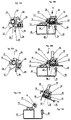
- FIG. 1 the individual parts of the hinge according to the invention in exploded view
- FIG. 2 the hinge in the assembled state with the individual parts of FIG. 1 , wherein the hinge is in the rest position;
- FIG. 3 the hinge after mounting in a sheet metal cabinet in the rest position, in a representation similar to FIG. 2 ;
- FIG. 4 the hinge with the second hinge part raised after a rotation through 180′;
- FIG. 5 a perspective view of the hinge following an initial use before the further rotation through 180° in the clockwise direction for moving out through pulling of the tongue;
- FIG. 6 the state with the tongue advanced (hinge function).
- FIG. 7 the state with the tongue retracted (hinge parts can be separated);
- FIG. 8 a top view of the hinge according to the invention in the lowered position
- FIG. 9 the hinge of FIG. 8 following separation into the two hinge parts
- FIG. 10 a cross-sectional view of the hinge according to the invention in the closed position (hinge function);
- FIG. 11 a similar view to FIG. 10 in the lowered position following rotation through 180′;
- FIG. 12 the position following rotation through 360°
- FIG. 13 a side view of the hinge mounted on the switch cabinet with seal
- FIG. 14 the arrangement of FIG. 13 following insertion of an actuator key and clockwise rotation of this through 180° (door lifts) (pressure equalization, seal is relaxed);
- FIG. 15 A an enlarged representation of the tongue in the locking position
- FIG. 15 B a similar view to FIG. 13 representing the internal arrangement of the hinge
- FIG. 16 A a similar view to FIG. 15 A, but with the tongue retracted;
- FIG. 16 B a similar view to FIG. 15 A of the state of FIG. 16 A;
- FIG. 17 A and FIG. 17 B a similar view to FIG. 16 B, but with the hinge taken apart;
- FIG. 18 a perspective view of the mounted and closed hinge
- FIG. 19 a perspective view of the mounted and relaxed hinge with key inserted
- FIG. 20 the hinge in the mounted and relaxed position without key
- FIG. 21 the mounted hinge following separation of the hinge parts
- FIG. 22 a side view of the hinge in the hinge function
- FIG. 23 a perspective representation of the hinge of FIG. 22 .
- FIG. 1 an exploded view of the hinge 8 according to the invention is illustrated, while FIG. 2 illustrates the assembled hinge 8 and FIG. 3 the hinge 8 after mounting in a door
- the hinge 8 for detachable sheet metal cabinet doors or walls, comprises a first hinge part first hinge part 10 that can be attached to the door or cabinet frame 34 , and a second hinge part 16 that can be fixed to the door leaf or cabinet wall 38 , which hinge parts 10 , 16 are connected to one another in an articulated manner by a hinge pin 14 with a spacer roller 12 , and having a latch-type tongue 26 that is arranged in the second hinge part 16 such that it can move against a spring force within the spring 24 , a lifting device 18 , which encompasses the hinge pin 14 guided through the finger-type ends 42 of the first hinge part 10 and which centrally supports the hinge pin with a hook 46 formed by the lifting device 18 , the lifting device moves the encompassing part or hook of the second hinge part 16 perpendicularly to the plane 62 of the door leaf or cabinet wall 16 by means of a key 40 , such as a double bit key, via an actuator 20 .
- a key 40 such as a double bit key
- the second hinge part 16 forms guide walls 58 , which provide a guide for the lifting device and encompass this in a U-shaped manner.
- the guide walls 58 are formed by a part 56 of the second hinge part 16 .
- the second hinge part also includes feet 48 with bore holes 50 for attaching the second hinge part 16 to the cabinet door by screws 52 .
- the lifting device supports the key housing 20 and the turntable 22 has a track 64 in which a projection 66 is inserted which protrudes from the bottom of the actuator 20 .
- the projection is formed by a head screw 30 , which is screwed into the bottom of the actuator. This facilitates mounting of the arrangement in its movement.
- the tongue 26 has an L-shaped cutout 60 , which guides the tongue upon rotation of the actuator such that upon rotation through 180° in a first direction (e.g. clockwise direction or right rotation) the guide walls 58 are raised, and that by rotation through a further 180° in the same direction (clockwise direction) the tongue is drawn into the guide walls 58 (see FIGS. 10, 11, 12 ).
- a hinge 9 which driven by a suitable key 40 in a rotatable actuator 20 accessible from the outside, allows a guide wall 58 of the hinge to perform a lifting or pressing movement away from or towards the first hinge part 10 , without affecting the hinge function.
- This is achieved by a pin 32 sitting in the second hinge part, which engages in a curved track located on the outer periphery of the actuator and thus allows the lifting or pressing movement.
- the turntable 22 in conjunction with carrier and spacer 28 ensures that only after the lifting movement the tongue 26 can be retracted by a further rotational movement of the key and thus a separation of the hinge is caused, and the hinge function is inhibited.
- the tongue is also provided with an override so that supported by a spring force the closing operation can be carried out without a key.
Landscapes
- Engineering & Computer Science (AREA)
- Mechanical Engineering (AREA)
- Hinges (AREA)
- Closing And Opening Devices For Wings, And Checks For Wings (AREA)
Applications Claiming Priority (3)
| Application Number | Priority Date | Filing Date | Title |
|---|---|---|---|
| DE202017004239.8 | 2017-08-12 | ||
| DE202017004239.8U DE202017004239U1 (de) | 2017-08-12 | 2017-08-12 | Scharnier für aushängbare Blechschranktüren oder -wände |
| PCT/EP2018/070997 WO2019034441A1 (fr) | 2017-08-12 | 2018-08-02 | Charnière pour portes ou parois amovibles d'armoire en tôle |
Publications (2)
| Publication Number | Publication Date |
|---|---|
| US20200165849A1 US20200165849A1 (en) | 2020-05-28 |
| US11313162B2 true US11313162B2 (en) | 2022-04-26 |
Family
ID=63350506
Family Applications (1)
| Application Number | Title | Priority Date | Filing Date |
|---|---|---|---|
| US16/638,255 Active US11313162B2 (en) | 2017-08-12 | 2018-08-02 | Hinge for detachable sheet metal cabinet doors or walls |
Country Status (6)
| Country | Link |
|---|---|
| US (1) | US11313162B2 (fr) |
| EP (1) | EP3665351B1 (fr) |
| DE (1) | DE202017004239U1 (fr) |
| ES (1) | ES3039344T3 (fr) |
| PL (1) | PL3665351T3 (fr) |
| WO (1) | WO2019034441A1 (fr) |
Cited By (4)
| Publication number | Priority date | Publication date | Assignee | Title |
|---|---|---|---|---|
| US20210017797A1 (en) * | 2018-02-20 | 2021-01-21 | Emka Beschlagteile Gmbh & Co. Kg | Hinge and method for adjusting a hinge |
| US20240076919A1 (en) * | 2022-08-31 | 2024-03-07 | RSI North America, Inc. | Hinge |
| US20240151080A1 (en) * | 2022-11-04 | 2024-05-09 | Fositek Corporation | Hinge |
| US12421775B2 (en) * | 2023-12-08 | 2025-09-23 | Fositek Corporation | Hinge with movable rotating axle |
Families Citing this family (6)
| Publication number | Priority date | Publication date | Assignee | Title |
|---|---|---|---|---|
| EP3591154A4 (fr) * | 2017-03-03 | 2021-01-06 | Sugatsune Kogyo Co., Ltd. | Charnière |
| EP3425147B1 (fr) * | 2017-07-03 | 2023-07-26 | Ningbo Geely Automobile Research & Development Co., Ltd. | Dispositif à charnière |
| EP3556979A1 (fr) * | 2018-04-19 | 2019-10-23 | ABB S.p.A. | Armoire électrique |
| US11299921B2 (en) * | 2020-03-17 | 2022-04-12 | The Boeing Company | Hinge assembly |
| DE102022123964A1 (de) * | 2022-09-19 | 2024-03-21 | Emka Beschlagteile Gmbh & Co. Kg | Scharnier |
| EP4594587A4 (fr) * | 2022-09-26 | 2025-12-03 | Samet Kalip Ve Madeni Esya San Ve Tic A S | Charnière pour assembler deux portes dans des armoires à portes pliantes |
Citations (18)
| Publication number | Priority date | Publication date | Assignee | Title |
|---|---|---|---|---|
| US2778053A (en) * | 1954-09-13 | 1957-01-22 | Duro Metal Products Co | Separable hinged mounting for motors or the like |
| US2913200A (en) * | 1954-07-06 | 1959-11-17 | Duro Metal Products Co | Separable mounting for electric motors or the like |
| EP0274549A1 (fr) | 1987-01-09 | 1988-07-20 | Dieter Ramsauer | Charnière cachée séparable pour armoires de commutation |
| US4873745A (en) * | 1987-01-09 | 1989-10-17 | Dieter Ramsauer | Unhingeable and concealed hinge for switching boxes |
| US5794310A (en) * | 1997-02-24 | 1998-08-18 | Truth Hardware Corporation | Adjustable window hinge |
| WO2007033714A1 (fr) * | 2005-09-24 | 2007-03-29 | Dieter Ramsauer | Dispositif de guidage pouvant etre monte sur un boulon d'entretoisement pour une tige ronde |
| US20070130726A1 (en) * | 2005-12-09 | 2007-06-14 | Industrilas Ab | Hinge and latch mechanism |
| US20080115327A1 (en) * | 2004-08-27 | 2008-05-22 | Mepla-Werke Lautenschlaeger Gmbh & Co. Kg | Mounting Plate for Adjustably Mounting Furniture Hinges on the Frame of Articles of Furniture |
| EP2405088A2 (fr) | 2010-07-08 | 2012-01-11 | Dr. Hahn GmbH & Co. KG | Paumelle pour le raccordement oscillant d'un battant avec un châssis |
| WO2012040945A2 (fr) | 2010-09-17 | 2012-04-05 | 高天(中山)金属制造有限公司 | Charnière réglable en trois dimensions |
| US9151101B2 (en) * | 2011-09-07 | 2015-10-06 | Hardware Resources, Inc. | Detachable hinge damper |
| US20150315832A1 (en) * | 2014-04-30 | 2015-11-05 | Zhiyong Wu | Soft-closing hinge for use in furniture |
| DE202015001918U1 (de) | 2015-03-12 | 2016-06-14 | Dirak Dieter Ramsauer Konstruktionselemente Gmbh | Scharnier für aushängbare Blechschranktüren |
| US20160208533A1 (en) * | 2015-01-16 | 2016-07-21 | Guangdong Taiming Metal Products Co. Ltd | Blind hinge used for furniture |
| DE202016003986U1 (de) * | 2016-06-28 | 2017-09-29 | Dirak Dieter Ramsauer Konstruktionselemente Gmbh | Aushängbares Verschwindscharnier für Schaltschränke oder dgl. |
| US20190323273A1 (en) * | 2017-04-21 | 2019-10-24 | Rittal Gmbh & Co. Kg | Hinge for a switchgear cabinet housing and corresponding switchgear cabinet housing and mounting method |
| US20200262689A1 (en) * | 2016-12-20 | 2020-08-20 | Doosan Corporation | Forklift side door |
| US20200371561A1 (en) * | 2019-05-21 | 2020-11-26 | Compal Electronics, Inc. | Seamless hinge and electronic device having the same |
-
2017
- 2017-08-12 DE DE202017004239.8U patent/DE202017004239U1/de not_active Expired - Lifetime
-
2018
- 2018-08-02 PL PL18759046.8T patent/PL3665351T3/pl unknown
- 2018-08-02 WO PCT/EP2018/070997 patent/WO2019034441A1/fr not_active Ceased
- 2018-08-02 EP EP18759046.8A patent/EP3665351B1/fr active Active
- 2018-08-02 ES ES18759046T patent/ES3039344T3/es active Active
- 2018-08-02 US US16/638,255 patent/US11313162B2/en active Active
Patent Citations (20)
| Publication number | Priority date | Publication date | Assignee | Title |
|---|---|---|---|---|
| US2913200A (en) * | 1954-07-06 | 1959-11-17 | Duro Metal Products Co | Separable mounting for electric motors or the like |
| US2778053A (en) * | 1954-09-13 | 1957-01-22 | Duro Metal Products Co | Separable hinged mounting for motors or the like |
| EP0274549A1 (fr) | 1987-01-09 | 1988-07-20 | Dieter Ramsauer | Charnière cachée séparable pour armoires de commutation |
| US4873745A (en) * | 1987-01-09 | 1989-10-17 | Dieter Ramsauer | Unhingeable and concealed hinge for switching boxes |
| US5794310A (en) * | 1997-02-24 | 1998-08-18 | Truth Hardware Corporation | Adjustable window hinge |
| US20080115327A1 (en) * | 2004-08-27 | 2008-05-22 | Mepla-Werke Lautenschlaeger Gmbh & Co. Kg | Mounting Plate for Adjustably Mounting Furniture Hinges on the Frame of Articles of Furniture |
| WO2007033714A1 (fr) * | 2005-09-24 | 2007-03-29 | Dieter Ramsauer | Dispositif de guidage pouvant etre monte sur un boulon d'entretoisement pour une tige ronde |
| US20070130726A1 (en) * | 2005-12-09 | 2007-06-14 | Industrilas Ab | Hinge and latch mechanism |
| EP2405088A2 (fr) | 2010-07-08 | 2012-01-11 | Dr. Hahn GmbH & Co. KG | Paumelle pour le raccordement oscillant d'un battant avec un châssis |
| US20120005859A1 (en) | 2010-07-08 | 2012-01-12 | Dr. Hahn Gmbh & Co. Kg | Strap hinge for the connection of a leaf to a frame so as to be pivotable about a hinge axis |
| WO2012040945A2 (fr) | 2010-09-17 | 2012-04-05 | 高天(中山)金属制造有限公司 | Charnière réglable en trois dimensions |
| US9151101B2 (en) * | 2011-09-07 | 2015-10-06 | Hardware Resources, Inc. | Detachable hinge damper |
| US20150315832A1 (en) * | 2014-04-30 | 2015-11-05 | Zhiyong Wu | Soft-closing hinge for use in furniture |
| US20160208533A1 (en) * | 2015-01-16 | 2016-07-21 | Guangdong Taiming Metal Products Co. Ltd | Blind hinge used for furniture |
| DE202015001918U1 (de) | 2015-03-12 | 2016-06-14 | Dirak Dieter Ramsauer Konstruktionselemente Gmbh | Scharnier für aushängbare Blechschranktüren |
| US20180044957A1 (en) * | 2015-03-12 | 2018-02-15 | Dirak Dieter Ramsauer Konstruktionselemente Gmbh | Hinge for Unhingeable Sheet-Metal Cabinet Doors |
| DE202016003986U1 (de) * | 2016-06-28 | 2017-09-29 | Dirak Dieter Ramsauer Konstruktionselemente Gmbh | Aushängbares Verschwindscharnier für Schaltschränke oder dgl. |
| US20200262689A1 (en) * | 2016-12-20 | 2020-08-20 | Doosan Corporation | Forklift side door |
| US20190323273A1 (en) * | 2017-04-21 | 2019-10-24 | Rittal Gmbh & Co. Kg | Hinge for a switchgear cabinet housing and corresponding switchgear cabinet housing and mounting method |
| US20200371561A1 (en) * | 2019-05-21 | 2020-11-26 | Compal Electronics, Inc. | Seamless hinge and electronic device having the same |
Cited By (7)
| Publication number | Priority date | Publication date | Assignee | Title |
|---|---|---|---|---|
| US20210017797A1 (en) * | 2018-02-20 | 2021-01-21 | Emka Beschlagteile Gmbh & Co. Kg | Hinge and method for adjusting a hinge |
| US11859427B2 (en) * | 2018-02-20 | 2024-01-02 | Emka Beschlagteile Gmbh & Co. Kg | Hinge and method for adjusting a hinge |
| US20240076919A1 (en) * | 2022-08-31 | 2024-03-07 | RSI North America, Inc. | Hinge |
| US12385301B2 (en) * | 2022-08-31 | 2025-08-12 | RSI North America, Inc. | Hinge |
| US20240151080A1 (en) * | 2022-11-04 | 2024-05-09 | Fositek Corporation | Hinge |
| US12286825B2 (en) * | 2022-11-04 | 2025-04-29 | Fositek Corporation | Hinge |
| US12421775B2 (en) * | 2023-12-08 | 2025-09-23 | Fositek Corporation | Hinge with movable rotating axle |
Also Published As
| Publication number | Publication date |
|---|---|
| EP3665351B1 (fr) | 2025-07-02 |
| PL3665351T3 (pl) | 2025-10-06 |
| EP3665351A1 (fr) | 2020-06-17 |
| DE202017004239U1 (de) | 2018-11-16 |
| US20200165849A1 (en) | 2020-05-28 |
| ES3039344T3 (en) | 2025-10-20 |
| WO2019034441A1 (fr) | 2019-02-21 |
Similar Documents
| Publication | Publication Date | Title |
|---|---|---|
| US20200165849A1 (en) | Hinge for Detachable Sheet Metal Cabinet Doors or Walls | |
| AU2014200054B2 (en) | Door Assembly | |
| KR20130097774A (ko) | 도어 클로저, 특히 유리 도어용 도어 클로저 | |
| GB2519396A (en) | Mechanism to facilitate cleaning of a closure | |
| US10400492B2 (en) | Hidden hinge | |
| CA2856577A1 (fr) | Fermeture de porte a support | |
| JP5284010B2 (ja) | 建具 | |
| KR20170018594A (ko) | 미닫이창용 열림 보조장치 | |
| DK2803787T3 (en) | DOOR SHUTTER FURNITURE | |
| KR20110002241U (ko) | 비상 자동문 잠금장치 | |
| CN109000415A (zh) | 一种助力拉手 | |
| GB2577351A (en) | A security door hinge assembly | |
| CN210342985U (zh) | 一种上悬窗自动锁闭装置 | |
| AU2014202056B2 (en) | Shower door assembly with linkage control | |
| IT202000005080A1 (it) | Mobile contenitore | |
| ES3009513T3 (en) | Thrust means for opening weathertight windows or doors | |
| CN110566071A (zh) | 天地铰链 | |
| KR20170054641A (ko) | 도어 잠금장치 | |
| KR101544144B1 (ko) | 힌지장치 | |
| KR101902476B1 (ko) | 도어용 경첩 | |
| KR20170040644A (ko) | 미닫이창용 열림 보조장치 | |
| KR200447878Y1 (ko) | 폴딩도어의 이동안내장치 | |
| EP2998497B1 (fr) | Charnière avec dispositif d'amortissement | |
| JP2013096159A (ja) | 引き戸用鎌錠 | |
| KR20180030368A (ko) | 프로젝트 창 경첩 |
Legal Events
| Date | Code | Title | Description |
|---|---|---|---|
| FEPP | Fee payment procedure |
Free format text: ENTITY STATUS SET TO UNDISCOUNTED (ORIGINAL EVENT CODE: BIG.); ENTITY STATUS OF PATENT OWNER: LARGE ENTITY |
|
| STPP | Information on status: patent application and granting procedure in general |
Free format text: DOCKETED NEW CASE - READY FOR EXAMINATION |
|
| AS | Assignment |
Owner name: DIRAK DIETER RAMSAUER KONSTRUKTIONSELEMENTE GMBH, GERMANY Free format text: ASSIGNMENT OF ASSIGNORS INTEREST;ASSIGNORS:OLKAY, CEM;HOESCHLER, PETER;REEL/FRAME:052320/0431 Effective date: 20200304 |
|
| STPP | Information on status: patent application and granting procedure in general |
Free format text: NON FINAL ACTION MAILED |
|
| STPP | Information on status: patent application and granting procedure in general |
Free format text: FINAL REJECTION MAILED |
|
| STPP | Information on status: patent application and granting procedure in general |
Free format text: RESPONSE AFTER FINAL ACTION FORWARDED TO EXAMINER |
|
| STPP | Information on status: patent application and granting procedure in general |
Free format text: ADVISORY ACTION MAILED |
|
| STPP | Information on status: patent application and granting procedure in general |
Free format text: RESPONSE AFTER FINAL ACTION FORWARDED TO EXAMINER |
|
| STPP | Information on status: patent application and granting procedure in general |
Free format text: NOTICE OF ALLOWANCE MAILED -- APPLICATION RECEIVED IN OFFICE OF PUBLICATIONS |
|
| STPP | Information on status: patent application and granting procedure in general |
Free format text: PUBLICATIONS -- ISSUE FEE PAYMENT VERIFIED |
|
| STCF | Information on status: patent grant |
Free format text: PATENTED CASE |
|
| MAFP | Maintenance fee payment |
Free format text: PAYMENT OF MAINTENANCE FEE, 4TH YEAR, LARGE ENTITY (ORIGINAL EVENT CODE: M1551); ENTITY STATUS OF PATENT OWNER: LARGE ENTITY Year of fee payment: 4 |