US11404792B2 - Antenna device - Google Patents
Antenna device Download PDFInfo
- Publication number
- US11404792B2 US11404792B2 US16/643,845 US201816643845A US11404792B2 US 11404792 B2 US11404792 B2 US 11404792B2 US 201816643845 A US201816643845 A US 201816643845A US 11404792 B2 US11404792 B2 US 11404792B2
- Authority
- US
- United States
- Prior art keywords
- slot
- antenna
- antenna device
- slit
- frequency band
- Prior art date
- Legal status (The legal status is an assumption and is not a legal conclusion. Google has not performed a legal analysis and makes no representation as to the accuracy of the status listed.)
- Active, expires
Links
Images




Classifications
-
- H—ELECTRICITY
- H01—ELECTRIC ELEMENTS
- H01Q—ANTENNAS, i.e. RADIO AERIALS
- H01Q13/00—Waveguide horns or mouths; Slot antennas; Leaky-waveguide antennas; Equivalent structures causing radiation along the transmission path of a guided wave
- H01Q13/10—Resonant slot antennas
- H01Q13/16—Folded slot antennas
-
- H—ELECTRICITY
- H01—ELECTRIC ELEMENTS
- H01Q—ANTENNAS, i.e. RADIO AERIALS
- H01Q13/00—Waveguide horns or mouths; Slot antennas; Leaky-waveguide antennas; Equivalent structures causing radiation along the transmission path of a guided wave
- H01Q13/10—Resonant slot antennas
-
- H—ELECTRICITY
- H01—ELECTRIC ELEMENTS
- H01Q—ANTENNAS, i.e. RADIO AERIALS
- H01Q1/00—Details of, or arrangements associated with, antennas
- H01Q1/27—Adaptation for use in or on movable bodies
- H01Q1/32—Adaptation for use in or on road or rail vehicles
- H01Q1/325—Adaptation for use in or on road or rail vehicles characterised by the location of the antenna on the vehicle
- H01Q1/3275—Adaptation for use in or on road or rail vehicles characterised by the location of the antenna on the vehicle mounted on a horizontal surface of the vehicle, e.g. on roof, hood, trunk
-
- H—ELECTRICITY
- H01—ELECTRIC ELEMENTS
- H01Q—ANTENNAS, i.e. RADIO AERIALS
- H01Q13/00—Waveguide horns or mouths; Slot antennas; Leaky-waveguide antennas; Equivalent structures causing radiation along the transmission path of a guided wave
- H01Q13/10—Resonant slot antennas
- H01Q13/103—Resonant slot antennas with variable reactance for tuning the antenna
-
- H—ELECTRICITY
- H01—ELECTRIC ELEMENTS
- H01Q—ANTENNAS, i.e. RADIO AERIALS
- H01Q13/00—Waveguide horns or mouths; Slot antennas; Leaky-waveguide antennas; Equivalent structures causing radiation along the transmission path of a guided wave
- H01Q13/10—Resonant slot antennas
- H01Q13/106—Microstrip slot antennas
-
- H—ELECTRICITY
- H01—ELECTRIC ELEMENTS
- H01Q—ANTENNAS, i.e. RADIO AERIALS
- H01Q21/00—Antenna arrays or systems
- H01Q21/28—Combinations of substantially independent non-interacting antenna units or systems
-
- H—ELECTRICITY
- H01—ELECTRIC ELEMENTS
- H01Q—ANTENNAS, i.e. RADIO AERIALS
- H01Q5/00—Arrangements for simultaneous operation of antennas on two or more different wavebands, e.g. dual-band or multi-band arrangements
- H01Q5/30—Arrangements for providing operation on different wavebands
- H01Q5/307—Individual or coupled radiating elements, each element being fed in an unspecified way
- H01Q5/314—Individual or coupled radiating elements, each element being fed in an unspecified way using frequency dependent circuits or components, e.g. trap circuits or capacitors
- H01Q5/321—Individual or coupled radiating elements, each element being fed in an unspecified way using frequency dependent circuits or components, e.g. trap circuits or capacitors within a radiating element or between connected radiating elements
-
- H—ELECTRICITY
- H01—ELECTRIC ELEMENTS
- H01Q—ANTENNAS, i.e. RADIO AERIALS
- H01Q5/00—Arrangements for simultaneous operation of antennas on two or more different wavebands, e.g. dual-band or multi-band arrangements
- H01Q5/30—Arrangements for providing operation on different wavebands
- H01Q5/307—Individual or coupled radiating elements, each element being fed in an unspecified way
- H01Q5/342—Individual or coupled radiating elements, each element being fed in an unspecified way for different propagation modes
- H01Q5/357—Individual or coupled radiating elements, each element being fed in an unspecified way for different propagation modes using a single feed point
- H01Q5/364—Creating multiple current paths
-
- H—ELECTRICITY
- H01—ELECTRIC ELEMENTS
- H01Q—ANTENNAS, i.e. RADIO AERIALS
- H01Q9/00—Electrically-short antennas having dimensions not more than twice the operating wavelength and consisting of conductive active radiating elements
- H01Q9/04—Resonant antennas
- H01Q9/30—Resonant antennas with feed to end of elongated active element, e.g. unipole
- H01Q9/42—Resonant antennas with feed to end of elongated active element, e.g. unipole with folded element, the folded parts being spaced apart a small fraction of the operating wavelength
Definitions
- the present invention relates to a small low-profile antenna device suitable for applications such as telematics.
- Telematics is a combination of the words “telecommunication” and “informatics”, and is a technique for providing information and services in real time to communications equipment of a vehicle using a mobile communications system and the like.
- Patent Literature 1 discloses an antenna device that conducts MIMO communication using a frequency band of LTE (Long Term Evolution) communication.
- LTE communication is a communications mode that speeds up the third generation (3G) communication.
- the MIMO (Multiple-Input Multiple-Output) communication is a communications mode that uses plural antennas, transmits different data from each antenna, and receives data simultaneously by the plural antennas.
- the antenna device disclosed in Patent Literature 1 includes plural antennas housed in a shark fin antenna housing with length 100 mm, width 50 mm, and height 45 mm.
- One of the antennas is an unbalanced antenna, i.e., a monopole antenna, which determines the height of the antenna device.
- antenna devices mounted on vehicles use a vehicle roof as a ground plane, and thus monopole antennas are used often.
- Patent Literature 1 National Publication of International Patent Application No. 2016-504799
- the antennas used for LTE communication and MIMO communication have high gain in the horizontal direction (direction parallel to the ground) orthogonal to the zenith direction (upward in the vertical direction). Also, antenna devices mounted on vehicles are required to be small and low-profile.
- a monopole antenna is made low-profile as with the antenna device disclosed in Patent Literature 1, the antenna size (height) in the zenith direction decreases, resulting in deterioration of a VSWR (Voltage Standing Wave Ratio) and shortage of gain in the horizontal direction.
- the monopole antenna can be made low-profile to some extent by loading an antenna coil and the like to satisfy a resonance condition or interposing an impedance matching circuit, but it is difficult to reduce deterioration of VSWR of the antenna itself or gain in the horizontal direction.
- to conduct MIMO communication using an antenna device for a vehicle it is necessary to mount plural antennas, and thus there is a limit to downsizing.
- An object of the present invention is to provide a small low-profile antenna device that can properly transmit and/or receive signals in a wide frequency band without providing an antenna coil and increase gain in the horizontal direction.
- the present invention provides an antenna device for a vehicle, the antenna device being fixed to a predetermined part of the vehicle and comprising at least one metal surface, wherein: a slot is formed in the metal surface with a slit provided at a part of edges of the slot; the slot faces a direction parallel to the ground; and a power feed unit is provided on inner edges between either slot end of the slot and the slit.
- a direction orthogonal to the antenna element corresponds to main polarization. Also, gain in an opening direction of the slot becomes high.
- the antenna device according to the present invention since the slot facing a direction parallel to the ground is formed in the metal surface, the gain in the direction parallel to the ground becomes high.
- the slit is provided at a part of edges of the slot and the power feed unit is provided on inner edges between either slot end of the slot and the slit, types of available frequency bands increase compared to when there is no slit. That is, bandwidth can be widened.
- FIG. 1 is a diagram illustrating installed condition of an antenna device according to an embodiment of the present invention.
- FIG. 2 is an explanatory diagram illustrating what are the names of faces of a rectangular enclosure.
- FIG. 3A is a pattern diagram for description of operation, illustrating a pattern in a reference side face.
- FIG. 3B is a pattern diagram for description of operation, illustrating a pattern in a modified slot antenna according to the present embodiment.
- FIG. 4 is a diagram illustrating a pattern example of a first side face.
- FIG. 5 is a diagram illustrating a pattern example of a second side face.
- FIG. 6 is a diagram illustrating a pattern example of a third side face.
- FIG. 7 is a diagram illustrating a pattern example of a fourth side face.
- FIG. 8 is a diagram illustrating a pattern example on a top face.
- FIG. 9 is an external view of an antenna unit according to the present embodiment.
- FIG. 10 is a characteristics comparison diagram of LTE's average gain vs. frequency.
- FIG. 11 is a comparison diagram of VSWR characteristics in LTE Low Band.
- FIG. 12 is a diagram illustrating a pattern example on a top face of an antenna according to a comparative example.
- FIG. 13 is a comparison diagram of VSWR characteristics between antennas according to the present embodiment and a comparative example.
- FIG. 14A is a VSWR characteristics diagram of a first power feed unit G 1 on the first side face.
- FIG. 14B is a VSWR characteristics diagram of a second power feed unit G 2 on the second side face.
- FIG. 15A is a VSWR characteristics diagram of a third power feed unit G 3 on the third side face.
- FIG. 15B is a VSWR characteristics diagram of a fourth power feed unit G 4 on the fourth side face.
- FIG. 16A is a characteristics diagram of average gain (dBi) of a first LTE antenna for vertically polarized waves in a horizontal direction.
- FIG. 16B is a characteristics diagram of average gain (dBi) of a second LTE antenna for vertically polarized waves in the horizontal direction.
- FIG. 17A is a characteristics diagram of average gain (dBi) of a third LTE antenna for vertically polarized waves in the horizontal direction.
- FIG. 17B is a characteristics diagram of average gain (dBi) of a fourth LTE antenna for vertically polarized waves in the horizontal direction.
- the antenna device can be used for reception from global satellite measurement systems as well as, for example, in LTE and V2X (Vehicle-to-everything).
- V2X is a communications mode that enables communication between communications equipment of a vehicle and everything around the vehicle.
- the antenna device is used as a vehicle-mounted antenna device housed in a storage space of a housing.
- FIG. 1 is a diagram illustrating installed condition of an antenna device according to an embodiment of the present invention.
- the antenna device 1 is made up of an antenna unit housed in a radio-wave transparent housing of a predetermined shape and predetermined size, allowing itself to be used by being mounted, for example, in a depression 501 on a vehicle roof 500 .
- the antenna unit has a resin-made rectangular box-shaped enclosure (hereinafter simply referred to as an “enclosure”) whose short sides are approximately 100 mm, long sides are approximately 200 mm, and height is approximately 17 mm. Slots and slits are formed integrally in the enclosure using LDS (Laser Direct Structuring) technology and electronic components and a circuit board are mounted in the enclosure.
- LDS Laser Direct Structuring
- the LDS technology is a common technology that involves drawing a three-dimensional pattern on resin by abrasion and then selectively metal-plating only traces of the abrasion using laser.
- FIG. 2 is a perspective view of the enclosure of the antenna unit with the housing removed. While details of patterns will be described later, hereinafter the entire short end face on the left side of FIG. 2 is referred to as a “second side face,” the other entire short end face not visible in FIG. 2 is referred to as a “first side face,” the entire long end face on the near side of FIG. 2 is referred to as a “fourth side face,” and the entire long end face not visible in FIG. 2 is referred to as a “third side face.”
- the first side face, second side face, third side face, and fourth side face are orthogonal to a ground plane (plane at ground potential) and oriented in different directions at 90 degree intervals. Thus, all 360-degree directions are covered during use. Also, an entire upper base of the enclosure is referred to as a “top face” and an entire lower base not visible in FIG. 2 is referred to as a “bottom face.” These faces are metal surfaces formed by covering areas on resin surfaces excluding predetermined patterns (patterns of plural slots and slits described later) with a metal film. These metal surfaces are placed in contact with other adjacent metal surfaces at a predetermined angle (90 degrees in this example).
- One of the features of the antenna device 1 according to the present embodiment is that a pair of modified slot antennas, a pair of slit antennas, and a pair of second slot antennas, which have been widened in bandwidth, are formed in a single enclosure.
- FIG. 3A is a pattern diagram of a reference face for description of operation.
- a slot 180 serving as an antenna element is formed in a center portion of the reference side face. There is a metal film 160 around the slot 180 .
- the slot 180 is parallel to the ground plane.
- a power feed unit Go for the slot 180 is provided on inner edges of the slot 180 .
- the slot 180 includes a first slot end (closed end on the left side of FIG. 3A ) and a second slot end (closed end on the right side of FIG. 3A ), which face the power feed unit Go from opposite directions.
- the length from the first slot end to the power feed unit Go is 1 ⁇ 2 a wavelength ⁇ L of a frequency used in a low-frequency band.
- the length from the second slot end to the power feed unit Go is 1 ⁇ 2 a wavelength ⁇ H of a frequency used in a high-frequency band, the second slot end being located on the opposite side of the slot 180 from the first slot end.
- FIG. 3B is a pattern diagram of a modified slot antenna, in which a slit 181 is formed in a part of edges of the slot 180 .
- the modified slot antenna has the same element structure as in FIG. 3A except that a part of edges of a metal film 161 is notched to thereby provide the slit 181 at the part of edges.
- the length from the first slot end of the slot 180 to the power feed unit Go is 1 ⁇ 2 the wavelength ⁇ L of the frequency used in a low-frequency band and the length from the second slot end of the slot 180 to the power feed unit Go is 1 ⁇ 2 the wavelength ⁇ H of the frequency used in a high-frequency band.
- the length from the first slot end of the slot 180 to an open end of the slit 181 is 1 ⁇ 4 a wavelength ⁇ L1 of a frequency used in another low-frequency band.
- the length from the open end of the slit 181 to the power feed unit Go is 1 ⁇ 4 a wavelength ⁇ L2 of a frequency used in still another low-frequency band.
- the frequency available for use in each frequency band has a certain range (width). Therefore, when a wavelength or resonant length is mentioned, it is assumed that the term means a certain range (width) of wavelengths or resonant lengths centering around a frequency to be used.
- the wavelength ⁇ L1 , wavelength ⁇ L , and wavelength ⁇ L2 are wavelengths of frequencies belonging to the low-frequency band, and the wavelength ⁇ H is a wavelength of a frequency belonging to the high-frequency band.
- the wavelength ⁇ L1 is a wavelength of the first frequency band, and that 1 ⁇ 4 the wavelength ⁇ L1 is a resonant length of the first frequency band.
- the wavelength ⁇ L is a wavelength of the second frequency band, and that 1 ⁇ 2 the wavelength ⁇ L is a resonant length of the second frequency band.
- the wavelength ⁇ L2 is a wavelength of the third frequency band, and that 1 ⁇ 4 the wavelength ⁇ L2 is a resonant length of the third frequency band.
- the wavelength ⁇ H is a wavelength of the fourth frequency band belonging to the high-frequency band, and that 1 ⁇ 2 the wavelength ⁇ H is a resonant length of the fourth frequency band.
- the modified slot antenna operates as a slot antenna capable of transmitting and/or receiving not only signals in the second frequency band and signals in the fourth frequency band able to be transmitted and/or received by the slot antenna illustrated in FIG. 3A , but also signals in the first frequency band and signals in the third frequency band.
- This increases the number of frequency bands available for use, as compared with a case where the slit 181 is not provided, and thereby enables bandwidth widening. By further increasing the number of slits, it will become possible to transmit or receive signals in four or more frequency bands.
- main polarization occurs in a direction orthogonal to the slot 180 , which is a main element of the antenna. Therefore, the main polarization of these slot antennas becomes a vertically polarized wave. As long as the slot 180 is parallel to the ground plane, the main polarization of these slot antennas becomes a vertically polarized wave, therefore, the metal film 160 does not necessarily have to be perpendicular to the ground plane. Also, with the slot antenna, the gain in the direction of a plane in which the slot 180 is formed becomes high.
- the modified slot antennas are applied to two LTE antennas capable of transmitting or receiving signals in the 700 MHz band, 800 MHz band, and 900 MHz band of LTE Low Band (low frequency bands: the same applies hereinafter) and 1.7 GHz to 2.7 GHz of LTE High Band (high frequency bands: the same applies hereinafter), respectively, that can be used in telematics and the like.
- the sizes of the slit 181 and slot 180 are determined and the position of the power feed unit Go on the inner edges of the slot 180 is determined, such that, for example, the first frequency band will be the 700 MHz band, the second frequency band will be the 800 MHz band, the third frequency band will be the 900 MHz band, and the fourth frequency band will be 1.7 GHz to 2.7 GHz.
- first LTE antenna One of the two modified slot antennas is referred to as a “first LTE antenna” and the other is referred to as a “second LTE antenna.”
- the first LTE antenna is formed together with a first power feed unit mainly on the first side face, third side face, and fourth side face of the rectangular box-shaped enclosure and the second LTE antenna is formed together with a second power feed unit mainly on the second side face, third side face, and fourth side face of the enclosure in such a way that the first LTE antenna and second LTE antenna will be point-symmetrical to each other.
- the two slit antennas used in LTE High Band are also formed integrally with the enclosure.
- One of the slit antennas is referred to as a “third LTE antenna” and the other slit antenna is referred to as a “fourth LTE antenna.”
- the third LTE antenna is formed together with a third power feed unit on the third side face of the enclosure.
- the fourth LTE antenna is formed together with a fourth power feed unit on the fourth side face of the enclosure.
- two slot antennas used as V2X antennas are further formed integrally with the enclosure.
- An allocated frequency band for V2X is the 5.9 GHz band.
- One of the slit antennas is referred to as a “first V2X antenna” and the other slot antenna is referred to as a “second V2X antenna.”
- the first V2X antenna is formed together with a fifth power feed unit on the fourth side face of the enclosure.
- the second V2X antenna is formed together with a sixth power feed unit on the second side face of the enclosure.
- a receiving antenna for global satellite measurement systems such as a GNSS (Global Navigation Satellite System) patch antenna (a flat antenna placed parallel to the ground plane) is further provided together with its power feed unit and circuit board in the enclosure.
- GNSS Global Navigation Satellite System
- patch antenna a flat antenna placed parallel to the ground plane
- the antenna unit which is created using the LDS technology, is created by covering resin with a metal film, the GNSS patch antenna and circuit board are not visible in FIG. 2 as well as in FIG. 9 described later, but arrangement and the like of these components will be described later with reference to FIG. 8 .
- the First LTE Antenna First Side Face, Third Side Face, Fourth Side Face, and Top Face
- the first LTE antenna is a modified slot antenna made up of a combination of a slot formed across the first side face, third side face, and fourth side face of the enclosure and a slit formed across the first side face and top face.
- FIG. 4 is a diagram illustrating a pattern example of the first side face.
- a slot 110 serving as a main element of the first LTE antenna is formed parallel to the ground plane.
- a slit 111 extending to the top face is provided at a part of edges of the slot 110 .
- a first power feed unit G 1 for the slot 110 is provided on inner edges of the slot 110 away from the slit 111 .
- power is fed by the first power feed unit G 1 with a core wire being connected to an upper edge (upper inner edge) of the slot 110 and with a ground wire being connected to a lower edge (lower inner edge) of the slot.
- a metal film is formed except for the slot 110 and slit 111 . That is, a pair of metal films are formed on opposite sides of the slot 110 , a metal film M 11 is formed on a top side of the first side face, and a metal film M 12 is formed on a bottom side.
- a high-pass filter 112 is interposed in an aperture in a part of the slit 111 which borders on the slot 110 .
- the high-pass filter 112 is designed to exhibit first impedance high enough to limit passage of signals in LTE Low Band and exhibit second impedance lower than the first impedance in LTE High Band.
- a switching element adapted to electrically open and close the aperture may be provided instead of the high-pass filter 112 .
- Operation of the first LTE antenna in Low Band is the same as the modified slot antenna of a basic configuration illustrated in FIG. 3B . That is, the length from an open end (open end in the top face) of the slit 111 to a slot end in the adjacent fourth side face corresponds to a resonant length of the 700 MHz band (1 ⁇ 4 the wavelength ⁇ L1 in the illustrated example). As can be seen from FIG. 2 , the “open end in the top face” means an end portion in which the aperture of the slit 111 widens. The length from the first power feed unit G 1 to the slot end in the fourth side face corresponds to a resonant length of the 800 MHz band (1 ⁇ 2 the wavelength ⁇ L in the illustrated example).
- the length from the open end (open end in the top face) of the slit 111 to the first power feed unit G 1 corresponds to a resonant length of the 900 MHz band (1 ⁇ 4 the wavelength ⁇ L2 in the illustrated example). Also, the length from the first power feed unit G 1 to a slot end in the adjacent third side face corresponds to a resonant length of the 2000 MHz band (1 ⁇ 2 the wavelength ⁇ H in the illustrated example). The length from the slot end in the third side face to the slot end in the fourth side face is equal to or more than twice a wavelength ⁇ H2 of the 2600 MHz band.
- the first LTE antenna has high gain for vertically polarized waves in the horizontal direction, in which the first side face is oriented.
- the first LTE antenna can be operated, for example, as a first antenna for 4 ⁇ 4 MIMO.
- Second LTE Antenna and Second V2X Antenna (Second Side Face, Third Side Face, Fourth Side Face, and Top Face)
- the second LTE antenna is a modified slot antenna made up of a combination of a slot formed across the second side face, third side face, and fourth side face of the enclosure and a slit formed across the second side face and top face.
- a pattern example of the second side face is illustrated in FIG. 5 .
- a slot 120 serving as an antenna element of the second LTE antenna is formed in a center portion of the second side face.
- a slit 121 extending to the top face is provided at a part of edges of the slot 120 .
- a second power feed unit G 2 for the slot 120 is provided on inner edges of the slot 120 away from the slit 121 .
- a high-pass filter 122 is interposed in an aperture in a part of the slit 121 which borders on the slot 120 . Shapes, sizes, circuit constants, and operation details of the slot 120 , slit 121 , and high-pass filter 122 are the same as those of the first LTE antenna.
- the second LTE antenna can be operated, for example, as a second antenna for 4 ⁇ 4 MIMO.
- the second LTE antenna has a structure point-symmetrical to that of the first LTE antenna when viewed from the top face. This makes it possible to secure a longer distance between the power feed units than when an axisymmetric structure is used and thereby reduce a correlation with the first LTE antenna. This in turn makes it possible, for example, to improve the throughput of MIMO communication.
- a slot 320 (second slot) operating as a second V2X antenna is also formed in the second side face.
- a sixth power feed unit G 6 is provided on inner edges of the slot 320 .
- the length from the sixth power feed unit G 6 to an end portion of the slot 320 is 1 ⁇ 2 the wavelength ⁇ v of the 5.9 GHz band of V2X (resonant length of frequency band of V2X).
- a metal film is formed except for the slots 120 and 320 and slit 121 . That is, a pair of metal films are formed on opposite sides of the slot 120 , a metal film M 21 is formed on a top side of the second side face, and a metal film M 22 is formed on a bottom side.
- the second LTE antenna has high gain for vertically polarized waves in the horizontal direction, in which the second side face is oriented.
- the third LTE antenna is a slit antenna formed across the top face and third side face of the enclosure.
- a pattern example of the third side face is illustrated in FIG. 6 .
- a slit 210 serving as a main element of the third LTE antenna an open end is formed in the top face and a closed end is formed at a location slightly offset toward the slot 120 from the midpoint between the slot 110 of the first LTE antenna and slot 120 of the second LTE antenna.
- the slit 210 is cut from the top face toward the bottom face substantially to the middle of the thickness, then changes direction toward the slot 120 of the second LTE antenna, and right afterwards terminates at a closed end.
- a third power feed unit G 3 for the slit is provided approximately in the midsection between the direction change position and the closed end.
- the length from the third power feed unit G 3 to the open end of the slit is 1 ⁇ 4 the wavelength ⁇ H of the 2000 MHz band in LTE High Band.
- a metal film M 3 is formed except for the slots 110 and 120 and slit 210 .
- the third LTE antenna can be prevented from interfering with the first LTE antenna and second LTE antenna.
- interference with the slot 110 of the first LTE antenna can be prevented more reliably, the slot 110 being located at a relatively large distance.
- the third LTE antenna has high gain for vertically polarized waves in the horizontal direction, in which the third side face is oriented.
- the third LTE antenna can be operated, for example, as a third antenna of 4 ⁇ 4 MIMO antennas.
- the fourth LTE antenna is a slit antenna formed across the top face and fourth side face of the enclosure.
- a pattern example of the fourth side face is illustrated in FIG. 7 .
- a slit 220 serving as a main element of the fourth LTE antenna an open end is formed in the top face and a closed end is formed at a location slightly offset toward the slot 120 from the midpoint between the slot 110 of the first LTE antenna and slot 120 of the second LTE antenna.
- the slit 220 is cut from the top face toward the bottom face substantially to the middle of the thickness, then changes direction toward the slot 120 of the second LTE antenna, and right afterwards terminates at a closed end.
- a fourth power feed unit G 4 for the slit 220 is provided on inner edges approximately in the midsection between the direction change position and the closed end.
- the length from the fourth power feed unit G 4 to the open end of the slit corresponds, for example, to a resonant length of the 2000 MHz band in LTE High Band (e.g., 1 ⁇ 4 the wavelength ⁇ H of the frequency band).
- the fourth LTE antenna can be prevented from interfering with the first LTE antenna and second LTE antenna.
- the fourth LTE antenna has high gain for vertically polarized waves in the horizontal direction, in which the fourth side face is oriented.
- the fourth LTE antenna can be operated, for example, as a fourth antenna for 4 ⁇ 4 MIMO.
- a slot 310 operating as the first V2X antenna is also formed in the fourth side face.
- a fifth power feed unit G 5 for the slot 310 is provided in the slot 310 .
- the length from the fifth power feed unit G 5 to an end portion of the slot 310 corresponds to a resonant length of the 5.9 GHz band of V2X (e.g., 1 ⁇ 2 the wavelength ⁇ v of a frequency band allocated to V2X).
- a metal film M 4 is formed except for the slots 110 , 120 , and 310 and slit 220 .
- the first V2X antenna can be used together with the second V2X antenna as a diversity antenna.
- FIG. 8 is a pattern diagram of the top face and FIG. 9 is an external view of the antenna unit (the same as FIG. 2 ).
- a circuit board 300 and patch antenna 400 placed parallel to the ground plane in the enclosure are indicated by broken lines in FIG. 8 .
- the placement location, shape, and size of the circuit board 300 are determined such that outer edges of the circuit board 300 will not overlap any of the slits 111 , 121 , 210 , and 220 and slots 110 , 120 , 310 , and 320 .
- the first power feed unit to the sixth power feed unit and circuit components electrically continuous with electronic equipment of the vehicle are mounted on the circuit board 300 .
- a ground wire (GND) of the circuit board 300 is electrically connected to the enclosure bottom face on which a metal film is formed.
- slits 111 , 121 , 210 , and 220 are formed in a resin top 100 , and consequently four metal films T 11 , T 12 , T 13 , and T 14 are formed on the top face, an exposing part of the resin top 100 .
- exposing part of the resin top 100 In the exposed part of the resin top 100 , two rectangles of different sizes intersect each other to thereby form a cross.
- the metal film T 11 on the top face is integral with the metal film M 21 which is one of metal films, from the end of the second side surface to the slit 121 , on the second side face and with the metal film M 3 on the third side face.
- the metal film T 12 on the top face is integral with the metal film M 3 on the third side face and with the metal film M 11 which is one of metal films, from the end of the first side surface to the slit 111 , on the first side face.
- the metal film T 13 on the top face is integral with the metal film M 11 which is one of metal films, from the end of the first side surface to the slit 111 , on the first side face and with the metal film M 4 on the fourth side face.
- the metal film T 14 on the top face is integral with the metal film M 4 on the fourth side face and with the metal film M 21 which is one of metal films, from the end of the second side surface to the slit 121 on the second side face. Since a metal film is also formed on the bottom face, the metal films T 11 , T 12 , T 13 , T 14 , M 11 , M 12 , M 21 , M 22 , M 3 , and M 4 are electrically continuous with one another.
- the vehicle roof 500 can be used as metal around the slots 110 , 120 , 310 , and 320 and slits 111 , 121 , 210 , and 220 , making it possible to improve antenna performance compared to in free space. Therefore, even if the antenna is placed in a depression surrounded by metal, deterioration of VSWR and gain in the horizontal direction is reduced compared to conventional monopole antennas.
- FIG. 10 is a characteristics comparison diagram of average gain in the horizontal direction based on differences in installed condition of the antenna device 1 and is result data of a predetermined simulator.
- the ordinate in FIG. 10 represents average gain (dBi) and the abscissa represents frequency (MHz).
- the solid line in FIG. 10 represents average gain obtained when the antenna device 1 is attached to the depression 501 on the vehicle roof 500 as illustrated in FIG. 1 .
- the broken line represents average gain obtained when the antenna device 1 is attached directly to the vehicle roof 500 without providing a depression 501 . Referring to FIG. 10 , there is no significant difference in average gain between these conditions. This means that the antenna device 1 according to the present embodiment eases restrictions on mounting positions on vehicles.
- a monopole antenna or dipole antenna is used for an antenna unit of a vehicle-mounted antenna device
- placement of the antenna device in a rear part of the vehicle roof will result in reduced gain in the horizontal direction, and thus it is considered desirable to place the antenna device in a front part of the vehicle roof.
- placement of the antenna device in the front part of the vehicle roof will impair vehicle design, and improvement is desired.
- the antenna device 1 according to the present embodiment eases restrictions on mounting positions and allows gain to be obtained at every azimuth in a horizontal plane. This solves the above problem.
- the antenna performance on the first side face to fourth side face of the antenna device 1 according to the present embodiment will be described later.
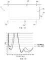
- the present inventors compared VSWR characteristics of the first LTE antenna formed on the first side face with VSWR characteristics of a comparative slot antenna having the same element structure except that the slit 111 was not formed in a part of edges of the slot 110 (the high-pass filter 112 was not added to the aperture of the slit 111 , either), i.e., only the slot 110 was provided.
- FIG. 11 is a comparison diagram of VSWR characteristics in LTE Low Band of the two antennas, illustrating measurement results produced by a predetermined simulator based on data of the first power feed unit G 1 .
- the solid line represents VSWR characteristics obtained when the slit 111 was provided and the broken line represents VSWR characteristics obtained when the slit 111 was not provided. Relationships (an extract) between frequency (MHz) and VSWR are as follows.
- FIG. 13 is a comparison diagram of VSWR characteristics in LTE frequency bands between antennas according to the present embodiment and a comparative example.
- the minimum value of VSWR in LTE Low Band is 2.66 (at 882 MHz) and VSWR is less than 4 in the frequency band of 315 MHz.
- the minimum value of VSWR is 3.85 (at 833 MHz) and VSWR is less than 4 in the frequency band of only 35 MHz.
- the antenna performance (electrical characteristics) on side faces of the antenna device 1 according to the present embodiment will be described.
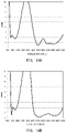
- FIG. 14A is a VSWR characteristics diagram of the first power feed unit G 1 on the first side face, details of which are as described with reference to the comparison diagram of VSWR characteristics in FIG. 11 .
- FIG. 14B is a VSWR characteristics diagram of the second power feed unit G 2 on the second side face. It can be seen that the second LTE antenna in the second side provides VSWR characteristics equal to or better than the first LTE antenna on the first side face.
- FIG. 15A is a VSWR characteristics diagram of the third power feed unit G 3 on the third side face and FIG. 15B is a VSWR characteristics diagram of the fourth power feed unit G 4 on the fourth side face. It can be seen that both antennas provide good VSWR characteristics in wide frequency ranges of 1800 MHz to 2700 MHz.
- FIG. 16A is a characteristics diagram of average gain (dBi) of the first LTE antenna for vertically polarized waves in the horizontal direction
- FIG. 16B is a characteristics diagram of average gain (dBi) of the second LTE antenna for vertically polarized waves in the horizontal direction. It can be seen that although the average gain falls in 1100 MHz to 1700 MHz not in use, good average gain (dBi) is obtained in Low Band including the 700 MHz band, 800 MHz band, and 900 MHz band and in High Band of 1700 MHz to 2700 MHz.
- FIG. 17A is a characteristics diagram of average gain (dBi) of the third LTE antenna for vertically polarized waves in the horizontal direction and FIG. 17B is a characteristics diagram of average gain (dBi) of the fourth LTE antenna for vertically polarized waves in the horizontal direction. Both antennas provide stable gain at 1500 MHz and above.
- the antenna device 1 includes the first LTE antenna in which the slot 110 extends parallel to the ground plane in the metal surface orthogonal to the ground plane and the slit 111 is provided at a part of edges of the slot 110 .
- the first power feed unit G 1 is provided on inner edges of the slot 110 away from the slit 111 and signals in four frequency bands are transmitted or received via the first power feed unit G 1 . Consequently, the number of available frequency bands increases compared to when the slit 111 is not provided and limited resources can be used effectively.
- a direction orthogonal to the slot 110 corresponds to main polarization
- the gain for vertically polarized waves can be maintained and the gain for vertically polarized waves can be increased in the opening direction of the slot 110 , i.e., in the horizontal direction. Consequently, by depressing part of the vehicle roof 500 and installing the antenna device 1 shaped and sized to fit in the depression 501 as illustrated in FIG. 1 , it is possible to make the antenna device 1 visually unrecognizable from outside while maintaining gain at every azimuth in the horizontal direction. This makes it possible to increase flexibility of vehicle design and achieve such an effect that cannot be obtained from conventional antenna devices of this type from the viewpoint of vehicle design.
- the antenna device 1 since a circuit that exhibits first impedance high enough to limit passage of signals in LTE Low Band and exhibit second impedance lower than the first impedance in LTE High Band is interposed in the aperture in a part of the slit 111 which borders on the slot 110 , the antenna device 1 according to the present embodiment can, in LTE High Band, mitigate an impact of the formed slit 111 and thereby stably reduce VSWR.
- the high-pass filter 112 is used as an example of the above-mentioned circuit, the circuit can be implemented, for example, by only an inductive reactance element and easily mounted in the slit 111 .
- a band-pass filter or a band-stop filter may be used instead of the high-pass filter 112 .
- the slot 110 is formed across the first side face as well as the third side face and fourth side face orthogonal to the ground plane with the third side face and fourth side face being connected to the ground plane in parallel to each other and with the first power feed unit G 1 being provided in the slot in the first side face, area can be saved for slot formation, making it possible to implement a small antenna. Slots may be formed only in the first side face and third side face or only in the first side face and fourth side face.
- the antenna device 1 can handle a larger number of frequency bands by making effective use of metal surfaces with limited areas.
- the slot 110 of the first LTE antenna and slot 120 of the second LTE antenna are placed in such a way as to be point-symmetrical to each other, it is possible to inhibit mutual interference, for example, when signals of the same frequency are transmitted or received.
- the antennas formed, respectively, on the first side face, second side face, third side face, and fourth side face oriented in different directions at 90 degree intervals in the horizontal direction operate as antennas for MIMO communication via their own power feed units, antennas capable of conducting MIMO communication in all directions are put together in a single enclosure, and, for example, an installation space on the vehicle can be further reduced.
- the antenna can be attached easily without reducing antenna performance (e.g., VSWR and horizontal gain).
- antenna performance e.g., VSWR and horizontal gain.
- the depression 501 can be reduced in size, eliminating the restrictions on the position of the depression 501 and thereby making it possible to further increase flexibility of vehicle design.
- gain can be ensured in all directions in the horizontal plane in spite of the small low-profile design, a wide variety of telematics communications can now be implemented in vehicles.
- the slots 110 and 120 and slits 111 , 121 , 210 , and 220 formed in plural metal surfaces are linked unicursally. That is, all the metal surfaces are continuous on the enclosure. This eliminates the need to join together the plural metal surfaces, thereby simplifies production of the antenna device 1 , and thus makes the antenna device 1 suitable for mass production.
- an antenna unit in which elements of plural antennas are formed integrally using the LDS technology, but the method of making an antenna unit is not restrained by the one described in the present embodiment, and, of course, an antenna unit may be constructed by gouging out a metal enclosure.
- the types of antennas formed on the first side face to the fourth side face can be changed as desired.
- the first LTE antenna may be formed on the third side face
- the second LTE antenna may be formed on the fourth side face
- the third LTE antenna may be formed on the first side face
- the fourth LTE antenna may be formed on the second side face
- the first V2X antenna may be formed on the first side face
- the second V2X antenna may be formed on the second side face, respectively.
- the shape of the enclosure is not limited to a rectangular box shape, and may be a polygonal box shape, columnar shape, or elliptic cylinder shape.
- first side face, second side face, third side face, and fourth side face which are orthogonal to the ground plane in the present embodiment, do not have to be orthogonal to the ground plane.
- the ground plane may be inclined with respect to the ground. Because gain for vertically polarized waves can be obtained as long as the slot 110 , slot 120 , slot 310 , and slot 320 are parallel to the ground plane, the first side face, second side face, third side face, and fourth side face may be at any angle to the ground plane.
- the slots 110 and 120 extend parallel to the ground plane in the metal surface orthogonal to the ground plane, but preferably the slots 110 and 120 are provided in such a way as to extend parallel to the ground.
- the slots 110 and 120 can be provided in the metal surface in such a way as to extend parallel to the ground.
- the slots 110 and 120 can be provided in such a way as to extend parallel to the ground.
- the slots 110 and 120 can be provided in such a way as to extend parallel to the ground.
- slots 310 and 320 are formed in the present embodiment, the slots 310 and 320 do not necessarily have to be formed.
- the antenna device 1 may be used for 2 ⁇ 2 MIMO. In that case, the slits 210 and 220 do not have to be formed.
Landscapes
- Engineering & Computer Science (AREA)
- Remote Sensing (AREA)
- Waveguide Aerials (AREA)
- Details Of Aerials (AREA)
- Support Of Aerials (AREA)
- Variable-Direction Aerials And Aerial Arrays (AREA)
Applications Claiming Priority (4)
| Application Number | Priority Date | Filing Date | Title |
|---|---|---|---|
| JP2017-170247 | 2017-09-05 | ||
| JPJP2017-170247 | 2017-09-05 | ||
| JP2017170247A JP6495985B2 (ja) | 2017-09-05 | 2017-09-05 | 車載用アンテナ装置 |
| PCT/JP2018/032822 WO2019049877A1 (ja) | 2017-09-05 | 2018-09-05 | アンテナ装置 |
Publications (2)
| Publication Number | Publication Date |
|---|---|
| US20210066808A1 US20210066808A1 (en) | 2021-03-04 |
| US11404792B2 true US11404792B2 (en) | 2022-08-02 |
Family
ID=65634167
Family Applications (1)
| Application Number | Title | Priority Date | Filing Date |
|---|---|---|---|
| US16/643,845 Active 2039-02-08 US11404792B2 (en) | 2017-09-05 | 2018-09-05 | Antenna device |
Country Status (5)
| Country | Link |
|---|---|
| US (1) | US11404792B2 (de) |
| EP (1) | EP3680985A4 (de) |
| JP (1) | JP6495985B2 (de) |
| CN (1) | CN111052506B (de) |
| WO (1) | WO2019049877A1 (de) |
Cited By (1)
| Publication number | Priority date | Publication date | Assignee | Title |
|---|---|---|---|---|
| US12592480B2 (en) | 2022-02-10 | 2026-03-31 | AGC Inc. | Vehicle antenna device and antenna module |
Families Citing this family (11)
| Publication number | Priority date | Publication date | Assignee | Title |
|---|---|---|---|---|
| JP6971163B2 (ja) * | 2018-02-13 | 2021-11-24 | 株式会社ヨコオ | アンテナ装置 |
| KR102578033B1 (ko) * | 2018-10-30 | 2023-09-13 | 엘지전자 주식회사 | 차량에 탑재되는 안테나 시스템 및 이를 구비하는 차량 |
| WO2021107188A1 (ko) * | 2019-11-28 | 2021-06-03 | 엘지전자 주식회사 | 차량에 탑재되는 안테나 시스템 |
| US11145962B2 (en) * | 2020-03-05 | 2021-10-12 | GM Global Technology Operations LLC | Conformal antennas formed at a surface of a vehicle |
| US11527810B2 (en) | 2020-11-16 | 2022-12-13 | Ford Global Technologies, Llc | Low-profile automotive universal antenna system |
| CN115117594A (zh) * | 2021-03-17 | 2022-09-27 | 北京小米移动软件有限公司 | 天线结构和电子设备 |
| CN115706317B (zh) * | 2021-08-12 | 2025-11-14 | 华为技术有限公司 | 一种天线结构和电子设备 |
| TWI793803B (zh) * | 2021-10-15 | 2023-02-21 | 啟碁科技股份有限公司 | 電子裝置與天線模組 |
| JP7805814B2 (ja) * | 2022-02-24 | 2026-01-26 | 株式会社デンソーテン | スロットアンテナ |
| TWI885595B (zh) * | 2023-11-24 | 2025-06-01 | 啓碁科技股份有限公司 | 通訊裝置 |
| CN119050643A (zh) * | 2024-09-14 | 2024-11-29 | 福耀玻璃工业集团股份有限公司 | 天线、玻璃天线和运载工具 |
Citations (13)
| Publication number | Priority date | Publication date | Assignee | Title |
|---|---|---|---|---|
| JPH02241207A (ja) | 1989-02-16 | 1990-09-25 | Robert Bosch Gmbh | スロットアンテナの形の車両アンテナ |
| JPH0361710U (de) | 1989-10-17 | 1991-06-17 | ||
| JP2002135045A (ja) | 2000-10-27 | 2002-05-10 | Fujitsu Ten Ltd | 複合アンテナ装置 |
| US20030122721A1 (en) * | 2001-12-27 | 2003-07-03 | Hrl Laboratories, Llc | RF MEMs-tuned slot antenna and a method of making same |
| JP2004242034A (ja) | 2003-02-05 | 2004-08-26 | Nippon Soken Inc | スロットアンテナ |
| US20120009884A1 (en) | 2010-07-12 | 2012-01-12 | Research In Motion Limited | Multiple Input Multiple Output Antenna Module and Associated Method |
| JP2012518371A (ja) | 2009-02-18 | 2012-08-09 | ハリス コーポレイション | 多重偏光機能を有する平面スロットアンテナ及び関連する方法 |
| EP2528165A1 (de) | 2011-05-27 | 2012-11-28 | Apple Inc. | Dynamisch anpassbare Antenne zur Unterstützung mehrerer Antennemodi |
| EP2811573A1 (de) | 2013-06-03 | 2014-12-10 | BlackBerry Limited | Breitbandantenne mit gekoppelter Zuleitung |
| WO2015111768A1 (ko) * | 2014-01-22 | 2015-07-30 | 한국과학기술원 | 빔공간 mimo 기반의 통신 장치, 및 이의 동작 방법 |
| JP2016504799A (ja) | 2012-11-09 | 2016-02-12 | ザ ユニバーシティ オブ バーミンガム | 車両用再構成可能mimoアンテナ |
| WO2017058177A1 (en) | 2015-09-29 | 2017-04-06 | Hewlett-Packard Development Company, L.P. | Coupled slot antennas |
| WO2017076750A1 (en) | 2015-11-02 | 2017-05-11 | Taoglas Limited | A multi-network telematics device with multiple antennas |
Family Cites Families (15)
| Publication number | Priority date | Publication date | Assignee | Title |
|---|---|---|---|---|
| JP3181075B2 (ja) * | 1991-08-02 | 2001-07-03 | 富士通テン株式会社 | 移動体用アンテナ |
| JP3473087B2 (ja) * | 1993-03-29 | 2003-12-02 | セイコーエプソン株式会社 | スロットアンテナ装置およびこのアンテナ装置を用いた無線機 |
| EP1376761B1 (de) * | 2001-03-15 | 2007-11-14 | Matsushita Electric Industrial Co., Ltd. | Antennenvorrichtung |
| JP2004128696A (ja) * | 2002-09-30 | 2004-04-22 | Harada Ind Co Ltd | 車両用アンテナ装置 |
| CN1778016A (zh) * | 2003-04-25 | 2006-05-24 | 住友电气工业株式会社 | 宽带平板天线 |
| JP4061258B2 (ja) * | 2003-09-18 | 2008-03-12 | セイコーインスツル株式会社 | 携帯用無線端末 |
| US6999037B2 (en) * | 2004-03-18 | 2006-02-14 | Bae Systems Information And Electronic Systems Integration Inc. | Meander-lineless wide bandwidth L-shaped slot line antenna |
| JP4819666B2 (ja) * | 2006-12-25 | 2011-11-24 | 富士通株式会社 | 無線機器 |
| US8912966B2 (en) * | 2007-10-19 | 2014-12-16 | Nxp, B.V. | Dual band slot antenna |
| WO2012059979A1 (ja) * | 2010-11-02 | 2012-05-10 | パイオニア株式会社 | 端末保持装置 |
| JP2013219572A (ja) * | 2012-04-10 | 2013-10-24 | Mitsumi Electric Co Ltd | アンテナ装置 |
| WO2015018070A1 (zh) * | 2013-08-09 | 2015-02-12 | 华为终端有限公司 | 印制电路板天线和终端 |
| WO2015135188A1 (zh) * | 2014-03-13 | 2015-09-17 | 华为终端有限公司 | 一种天线及终端 |
| CN105226371B (zh) * | 2014-05-26 | 2019-02-26 | 比亚迪股份有限公司 | 用于电子设备的天线系统和具有该天线系统的电子设备 |
| CN106537690A (zh) * | 2015-08-31 | 2017-03-22 | 华为技术有限公司 | 一种缝隙天线和终端设备 |
-
2017
- 2017-09-05 JP JP2017170247A patent/JP6495985B2/ja active Active
-
2018
- 2018-09-05 CN CN201880057470.8A patent/CN111052506B/zh active Active
- 2018-09-05 WO PCT/JP2018/032822 patent/WO2019049877A1/ja not_active Ceased
- 2018-09-05 EP EP18854870.5A patent/EP3680985A4/de not_active Withdrawn
- 2018-09-05 US US16/643,845 patent/US11404792B2/en active Active
Patent Citations (14)
| Publication number | Priority date | Publication date | Assignee | Title |
|---|---|---|---|---|
| JPH02241207A (ja) | 1989-02-16 | 1990-09-25 | Robert Bosch Gmbh | スロットアンテナの形の車両アンテナ |
| JPH0361710U (de) | 1989-10-17 | 1991-06-17 | ||
| JP2002135045A (ja) | 2000-10-27 | 2002-05-10 | Fujitsu Ten Ltd | 複合アンテナ装置 |
| US20030122721A1 (en) * | 2001-12-27 | 2003-07-03 | Hrl Laboratories, Llc | RF MEMs-tuned slot antenna and a method of making same |
| JP2004242034A (ja) | 2003-02-05 | 2004-08-26 | Nippon Soken Inc | スロットアンテナ |
| JP2012518371A (ja) | 2009-02-18 | 2012-08-09 | ハリス コーポレイション | 多重偏光機能を有する平面スロットアンテナ及び関連する方法 |
| US20120009884A1 (en) | 2010-07-12 | 2012-01-12 | Research In Motion Limited | Multiple Input Multiple Output Antenna Module and Associated Method |
| US9319155B2 (en) * | 2010-07-12 | 2016-04-19 | Blackberry Limited | Multiple input multiple output antenna module and associated method |
| EP2528165A1 (de) | 2011-05-27 | 2012-11-28 | Apple Inc. | Dynamisch anpassbare Antenne zur Unterstützung mehrerer Antennemodi |
| JP2016504799A (ja) | 2012-11-09 | 2016-02-12 | ザ ユニバーシティ オブ バーミンガム | 車両用再構成可能mimoアンテナ |
| EP2811573A1 (de) | 2013-06-03 | 2014-12-10 | BlackBerry Limited | Breitbandantenne mit gekoppelter Zuleitung |
| WO2015111768A1 (ko) * | 2014-01-22 | 2015-07-30 | 한국과학기술원 | 빔공간 mimo 기반의 통신 장치, 및 이의 동작 방법 |
| WO2017058177A1 (en) | 2015-09-29 | 2017-04-06 | Hewlett-Packard Development Company, L.P. | Coupled slot antennas |
| WO2017076750A1 (en) | 2015-11-02 | 2017-05-11 | Taoglas Limited | A multi-network telematics device with multiple antennas |
Non-Patent Citations (3)
| Title |
|---|
| Extended European search report dated Apr. 23, 2021, in corresponding European patent Application No. 18854870.5, 12 pages. |
| International Search Report and Written Opinion dated Nov. 20, 2018 for PCT/JP2018/032822 filed on Sep. 5, 2018, 7 pages including English Translation of the International Search Report. |
| Stanley, "A Novel Reconfigurable Metal Rim Integrated Open Slot Antenna for Octa-Band Smartphone Applications", Manoj Stanley, IEEE Transactions on Antennas and Propagation, vol. 65, No. 7, Jul. 2017. (Year: 2017). * |
Cited By (1)
| Publication number | Priority date | Publication date | Assignee | Title |
|---|---|---|---|---|
| US12592480B2 (en) | 2022-02-10 | 2026-03-31 | AGC Inc. | Vehicle antenna device and antenna module |
Also Published As
| Publication number | Publication date |
|---|---|
| EP3680985A4 (de) | 2021-05-26 |
| US20210066808A1 (en) | 2021-03-04 |
| JP2019047393A (ja) | 2019-03-22 |
| CN111052506B (zh) | 2022-11-04 |
| WO2019049877A1 (ja) | 2019-03-14 |
| JP6495985B2 (ja) | 2019-04-03 |
| EP3680985A1 (de) | 2020-07-15 |
| CN111052506A (zh) | 2020-04-21 |
Similar Documents
| Publication | Publication Date | Title |
|---|---|---|
| US11404792B2 (en) | Antenna device | |
| US11509053B2 (en) | Dual broadband antenna system for vehicles | |
| US11342680B2 (en) | Antenna device | |
| US20130082898A1 (en) | Antenna apparatus provided with two antenna elements and sleeve element for use in mobile communications | |
| CN102655268B (zh) | 多频带天线 | |
| US11152693B2 (en) | Antenna device | |
| US11862859B2 (en) | Antenna device | |
| US11024969B2 (en) | Multi-input multi-output antenna structure | |
| KR101718919B1 (ko) | 차량용 다중대역안테나 | |
| US12567680B2 (en) | Antenna device, array of antenna devices | |
| JP2022164538A (ja) | アンテナ構造及び無線通信装置 | |
| KR20090050566A (ko) | 차량 내 설치되는 mimo 시스템 | |
| JP2013232768A (ja) | 2周波共用アンテナ | |
| JP7100081B2 (ja) | 車載用アンテナ装置 | |
| JP2001144524A (ja) | 多周波共用アンテナ | |
| US12573769B2 (en) | Antenna device | |
| US11990692B2 (en) | Antenna module and vehicle comprising same | |
| JP4389863B2 (ja) | 統合アンテナ | |
| JPH08288731A (ja) | 2周波共用プリントアンテナ | |
| KR102117274B1 (ko) | 모노폴 안테나 및 이를 포함하는 안테나 모듈 | |
| JP2007124346A (ja) | アンテナ素子及びアレイ型アンテナ | |
| JP2019057958A (ja) | 車載用アンテナ装置 | |
| US20220224002A1 (en) | Antenna module and vehicle comprising same | |
| JP2022182168A (ja) | アンテナ装置 |
Legal Events
| Date | Code | Title | Description |
|---|---|---|---|
| AS | Assignment |
Owner name: YOKOWO CO., LTD., JAPAN Free format text: ASSIGNMENT OF ASSIGNORS INTEREST;ASSIGNOR:TANAKA, MASATO;REEL/FRAME:052072/0329 Effective date: 20200214 |
|
| FEPP | Fee payment procedure |
Free format text: ENTITY STATUS SET TO UNDISCOUNTED (ORIGINAL EVENT CODE: BIG.); ENTITY STATUS OF PATENT OWNER: LARGE ENTITY |
|
| STPP | Information on status: patent application and granting procedure in general |
Free format text: APPLICATION DISPATCHED FROM PREEXAM, NOT YET DOCKETED |
|
| STPP | Information on status: patent application and granting procedure in general |
Free format text: DOCKETED NEW CASE - READY FOR EXAMINATION |
|
| STPP | Information on status: patent application and granting procedure in general |
Free format text: NON FINAL ACTION MAILED |
|
| STPP | Information on status: patent application and granting procedure in general |
Free format text: RESPONSE TO NON-FINAL OFFICE ACTION ENTERED AND FORWARDED TO EXAMINER |
|
| STPP | Information on status: patent application and granting procedure in general |
Free format text: NOTICE OF ALLOWANCE MAILED -- APPLICATION RECEIVED IN OFFICE OF PUBLICATIONS |
|
| STCF | Information on status: patent grant |
Free format text: PATENTED CASE |
|
| FEPP | Fee payment procedure |
Free format text: MAINTENANCE FEE REMINDER MAILED (ORIGINAL EVENT CODE: REM.); ENTITY STATUS OF PATENT OWNER: LARGE ENTITY |