US11419968B2 - Apparatus for extracorporeal treatment of blood - Google Patents
Apparatus for extracorporeal treatment of blood Download PDFInfo
- Publication number
- US11419968B2 US11419968B2 US16/321,115 US201716321115A US11419968B2 US 11419968 B2 US11419968 B2 US 11419968B2 US 201716321115 A US201716321115 A US 201716321115A US 11419968 B2 US11419968 B2 US 11419968B2
- Authority
- US
- United States
- Prior art keywords
- blood
- fluid
- line
- temperature
- recirculation
- Prior art date
- Legal status (The legal status is an assumption and is not a legal conclusion. Google has not performed a legal analysis and makes no representation as to the accuracy of the status listed.)
- Active, expires
Links
Images


Classifications
-
- A—HUMAN NECESSITIES
- A61—MEDICAL OR VETERINARY SCIENCE; HYGIENE
- A61M—DEVICES FOR INTRODUCING MEDIA INTO, OR ONTO, THE BODY; DEVICES FOR TRANSDUCING BODY MEDIA OR FOR TAKING MEDIA FROM THE BODY; DEVICES FOR PRODUCING OR ENDING SLEEP OR STUPOR
- A61M1/00—Suction or pumping devices for medical purposes; Devices for carrying-off, for treatment of, or for carrying-over, body-liquids; Drainage systems
- A61M1/14—Dialysis systems; Artificial kidneys; Blood oxygenators ; Reciprocating systems for treatment of body fluids, e.g. single needle systems for hemofiltration or pheresis
- A61M1/16—Dialysis systems; Artificial kidneys; Blood oxygenators ; Reciprocating systems for treatment of body fluids, e.g. single needle systems for hemofiltration or pheresis with membranes
- A61M1/1694—Dialysis systems; Artificial kidneys; Blood oxygenators ; Reciprocating systems for treatment of body fluids, e.g. single needle systems for hemofiltration or pheresis with membranes with recirculating dialysing liquid
-
- A—HUMAN NECESSITIES
- A61—MEDICAL OR VETERINARY SCIENCE; HYGIENE
- A61M—DEVICES FOR INTRODUCING MEDIA INTO, OR ONTO, THE BODY; DEVICES FOR TRANSDUCING BODY MEDIA OR FOR TAKING MEDIA FROM THE BODY; DEVICES FOR PRODUCING OR ENDING SLEEP OR STUPOR
- A61M1/00—Suction or pumping devices for medical purposes; Devices for carrying-off, for treatment of, or for carrying-over, body-liquids; Drainage systems
- A61M1/14—Dialysis systems; Artificial kidneys; Blood oxygenators ; Reciprocating systems for treatment of body fluids, e.g. single needle systems for hemofiltration or pheresis
- A61M1/16—Dialysis systems; Artificial kidneys; Blood oxygenators ; Reciprocating systems for treatment of body fluids, e.g. single needle systems for hemofiltration or pheresis with membranes
- A61M1/1621—Constructional aspects thereof
- A61M1/1629—Constructional aspects thereof with integral heat exchanger
-
- A—HUMAN NECESSITIES
- A61—MEDICAL OR VETERINARY SCIENCE; HYGIENE
- A61M—DEVICES FOR INTRODUCING MEDIA INTO, OR ONTO, THE BODY; DEVICES FOR TRANSDUCING BODY MEDIA OR FOR TAKING MEDIA FROM THE BODY; DEVICES FOR PRODUCING OR ENDING SLEEP OR STUPOR
- A61M1/00—Suction or pumping devices for medical purposes; Devices for carrying-off, for treatment of, or for carrying-over, body-liquids; Drainage systems
- A61M1/14—Dialysis systems; Artificial kidneys; Blood oxygenators ; Reciprocating systems for treatment of body fluids, e.g. single needle systems for hemofiltration or pheresis
- A61M1/16—Dialysis systems; Artificial kidneys; Blood oxygenators ; Reciprocating systems for treatment of body fluids, e.g. single needle systems for hemofiltration or pheresis with membranes
- A61M1/1654—Dialysates therefor
- A61M1/1656—Apparatus for preparing dialysates
- A61M1/1658—Degasification
-
- A—HUMAN NECESSITIES
- A61—MEDICAL OR VETERINARY SCIENCE; HYGIENE
- A61M—DEVICES FOR INTRODUCING MEDIA INTO, OR ONTO, THE BODY; DEVICES FOR TRANSDUCING BODY MEDIA OR FOR TAKING MEDIA FROM THE BODY; DEVICES FOR PRODUCING OR ENDING SLEEP OR STUPOR
- A61M1/00—Suction or pumping devices for medical purposes; Devices for carrying-off, for treatment of, or for carrying-over, body-liquids; Drainage systems
- A61M1/14—Dialysis systems; Artificial kidneys; Blood oxygenators ; Reciprocating systems for treatment of body fluids, e.g. single needle systems for hemofiltration or pheresis
- A61M1/16—Dialysis systems; Artificial kidneys; Blood oxygenators ; Reciprocating systems for treatment of body fluids, e.g. single needle systems for hemofiltration or pheresis with membranes
- A61M1/1654—Dialysates therefor
- A61M1/1656—Apparatus for preparing dialysates
- A61M1/166—Heating
- A61M1/1664—Heating with temperature control
-
- A—HUMAN NECESSITIES
- A61—MEDICAL OR VETERINARY SCIENCE; HYGIENE
- A61M—DEVICES FOR INTRODUCING MEDIA INTO, OR ONTO, THE BODY; DEVICES FOR TRANSDUCING BODY MEDIA OR FOR TAKING MEDIA FROM THE BODY; DEVICES FOR PRODUCING OR ENDING SLEEP OR STUPOR
- A61M1/00—Suction or pumping devices for medical purposes; Devices for carrying-off, for treatment of, or for carrying-over, body-liquids; Drainage systems
- A61M1/34—Filtering material out of the blood by passing it through a membrane, i.e. hemofiltration or diafiltration
- A61M1/3496—Plasmapheresis; Leucopheresis; Lymphopheresis
-
- A—HUMAN NECESSITIES
- A61—MEDICAL OR VETERINARY SCIENCE; HYGIENE
- A61M—DEVICES FOR INTRODUCING MEDIA INTO, OR ONTO, THE BODY; DEVICES FOR TRANSDUCING BODY MEDIA OR FOR TAKING MEDIA FROM THE BODY; DEVICES FOR PRODUCING OR ENDING SLEEP OR STUPOR
- A61M1/00—Suction or pumping devices for medical purposes; Devices for carrying-off, for treatment of, or for carrying-over, body-liquids; Drainage systems
- A61M1/36—Other treatment of blood in a by-pass of the natural circulatory system, e.g. temperature adaptation, irradiation ; Extra-corporeal blood circuits
- A61M1/3607—Regulation parameters
- A61M1/3609—Physical characteristics of the blood, e.g. haematocrit, urea
- A61M1/3612—Physical characteristics of the blood, e.g. haematocrit, urea after treatment
-
- A—HUMAN NECESSITIES
- A61—MEDICAL OR VETERINARY SCIENCE; HYGIENE
- A61M—DEVICES FOR INTRODUCING MEDIA INTO, OR ONTO, THE BODY; DEVICES FOR TRANSDUCING BODY MEDIA OR FOR TAKING MEDIA FROM THE BODY; DEVICES FOR PRODUCING OR ENDING SLEEP OR STUPOR
- A61M1/00—Suction or pumping devices for medical purposes; Devices for carrying-off, for treatment of, or for carrying-over, body-liquids; Drainage systems
- A61M1/36—Other treatment of blood in a by-pass of the natural circulatory system, e.g. temperature adaptation, irradiation ; Extra-corporeal blood circuits
- A61M1/3621—Extra-corporeal blood circuits
- A61M1/3627—Degassing devices; Buffer reservoirs; Drip chambers; Blood filters
- A61M1/3629—Degassing devices; Buffer reservoirs; Drip chambers; Blood filters degassing by changing pump speed, e.g. during priming
-
- A—HUMAN NECESSITIES
- A61—MEDICAL OR VETERINARY SCIENCE; HYGIENE
- A61M—DEVICES FOR INTRODUCING MEDIA INTO, OR ONTO, THE BODY; DEVICES FOR TRANSDUCING BODY MEDIA OR FOR TAKING MEDIA FROM THE BODY; DEVICES FOR PRODUCING OR ENDING SLEEP OR STUPOR
- A61M1/00—Suction or pumping devices for medical purposes; Devices for carrying-off, for treatment of, or for carrying-over, body-liquids; Drainage systems
- A61M1/14—Dialysis systems; Artificial kidneys; Blood oxygenators ; Reciprocating systems for treatment of body fluids, e.g. single needle systems for hemofiltration or pheresis
- A61M1/15—Dialysis systems; Artificial kidneys; Blood oxygenators ; Reciprocating systems for treatment of body fluids, e.g. single needle systems for hemofiltration or pheresis with a cassette forming partially or totally the flow circuit for the treating fluid, e.g. the dialysate fluid circuit or the treating gas circuit
- A61M1/153—Dialysis systems; Artificial kidneys; Blood oxygenators ; Reciprocating systems for treatment of body fluids, e.g. single needle systems for hemofiltration or pheresis with a cassette forming partially or totally the flow circuit for the treating fluid, e.g. the dialysate fluid circuit or the treating gas circuit the cassette being adapted for heating or cooling the treating fluid, e.g. the dialysate or the treating gas
-
- A—HUMAN NECESSITIES
- A61—MEDICAL OR VETERINARY SCIENCE; HYGIENE
- A61M—DEVICES FOR INTRODUCING MEDIA INTO, OR ONTO, THE BODY; DEVICES FOR TRANSDUCING BODY MEDIA OR FOR TAKING MEDIA FROM THE BODY; DEVICES FOR PRODUCING OR ENDING SLEEP OR STUPOR
- A61M2205/00—General characteristics of the apparatus
- A61M2205/33—Controlling, regulating or measuring
- A61M2205/3331—Pressure; Flow
-
- A—HUMAN NECESSITIES
- A61—MEDICAL OR VETERINARY SCIENCE; HYGIENE
- A61M—DEVICES FOR INTRODUCING MEDIA INTO, OR ONTO, THE BODY; DEVICES FOR TRANSDUCING BODY MEDIA OR FOR TAKING MEDIA FROM THE BODY; DEVICES FOR PRODUCING OR ENDING SLEEP OR STUPOR
- A61M2205/00—General characteristics of the apparatus
- A61M2205/33—Controlling, regulating or measuring
- A61M2205/3368—Temperature
-
- A—HUMAN NECESSITIES
- A61—MEDICAL OR VETERINARY SCIENCE; HYGIENE
- A61M—DEVICES FOR INTRODUCING MEDIA INTO, OR ONTO, THE BODY; DEVICES FOR TRANSDUCING BODY MEDIA OR FOR TAKING MEDIA FROM THE BODY; DEVICES FOR PRODUCING OR ENDING SLEEP OR STUPOR
- A61M2205/00—General characteristics of the apparatus
- A61M2205/36—General characteristics of the apparatus related to heating or cooling
-
- A—HUMAN NECESSITIES
- A61—MEDICAL OR VETERINARY SCIENCE; HYGIENE
- A61M—DEVICES FOR INTRODUCING MEDIA INTO, OR ONTO, THE BODY; DEVICES FOR TRANSDUCING BODY MEDIA OR FOR TAKING MEDIA FROM THE BODY; DEVICES FOR PRODUCING OR ENDING SLEEP OR STUPOR
- A61M2230/00—Measuring parameters of the user
- A61M2230/50—Temperature
Definitions
- the present invention relates to an apparatus for extracorporeal treatment of blood.
- the extracorporeal blood treatment apparatus according to the invention is combined with, or comprises, a blood-warming device.
- the blood-warming device may be part of the extracorporeal blood treatment apparatus or may be a separate device which is in communication with the extracorporeal blood treatment apparatus.
- the invention also concerns a method of controlling blood warming in an extracorporeal blood circuit of an extracorporeal blood treatment apparatus.
- Extracorporeal blood treatment involves removing blood from a patient, treating the blood externally to the patient, and returning the treated blood to the patient.
- Extracorporeal blood treatment is typically used to extract undesirable matter or molecules from the patient's blood and/or to add desirable matter or molecules to the blood.
- Extracorporeal blood treatment is used with patients unable to effectively remove matter from their blood, such as when a patient has suffered temporary or permanent kidney failure. These patients and other patients may undergo extracorporeal blood treatment to add or remove matter to their blood, to maintain an acid/base balance or to remove excess body fluids, for example.
- Extracorporeal blood treatment is typically accomplished by removing the blood from the patient in e.g. a continuous flow, introducing the blood into a primary chamber, also referred to as blood chamber, of a treatment unit (such as a dialyzer or an Nemo-filter) where the blood is allowed to flow past a semi-permeable membrane.
- a treatment unit such as a dialyzer or an Nemo-filter
- the semi-permeable membrane selectively allows matter in the blood to cross the membrane from the primary chamber into a secondary chamber and also selectively allows matter in the secondary chamber to cross the membrane into the blood in the primary chamber, depending on the type of treatment.
- a number of different types of extracorporeal blood treatments may be performed.
- UF ultrafiltration
- HF hemofiltration
- the blood flows past the semipermeable membrane as in UF (where waste and undesirable fluid are removed) and desirable matter is added to the blood, typically by dispensing a fluid into the blood either before and/or after it passes through the treatment unit and before it is returned to the patient.
- a hemodialysis (HD) treatment a secondary fluid containing desirable matter is introduced into the secondary chamber of the treatment unit. Undesirable matter from the blood crosses the semipermeable membrane into the secondary fluid by diffusion and desirable matter from the secondary fluid crosses the membrane into the blood.
- HDF hemodiafiltration
- the patient may lose significant amount of heat due to infusion fluids having lower temperature than blood, due to fluid exchange across the membrane of the treatment unit, and due to heat lost to the atmosphere.
- extracorporeal blood treatments may last from several hours up to several days, the patient is put at risk of hypothermia in case no preventive measures are taken.
- This risk is, for example, present both in the case of relatively short treatments with high volume exchange, like chronic HD or HDF, and in the case of low volume but continuous therapies like continuous renal replacement therapy (CRRT) (used in e.g. acute HD).
- CRRT continuous renal replacement therapy
- the risk of hypothermia is even more problematic in case of treatments applied to low body weight patients, such as children.
- Blood cooling due to fluid exchange (treatment and/or infusion fluids) is usually more important than heat losses to atmosphere in the complete extracorporeal blood circuit.
- several solutions have been developed in the past.
- Blood warmers acting on the blood return line and capable of directly warming blood have been used. Blood warming introduces at least one additional component in the blood circuit, with the associated risks related to clotting and/or haemolysis.
- patient's blood cooling is prevented by warming each of the infusion fluids prior to their infusion in the blood circuit or dialyzer.
- These fluid warming systems have some drawbacks. When fluids of different compositions have to be used for the therapy, these systems become cumbersome due to the number of warming systems and associated disposable. Testing has evidenced strong limitations in the performance of current fluid warming systems when the fluid exchange rate becomes low (typically ⁇ 2000 ml/h), with the impossibility to compensate for the heat losses to atmosphere of the blood circuit.
- Document EP2319551 discloses an apparatus for hemodialysis comprising a dialyzer, an ultrafilter and an external dialysate circuit which provides fresh dialysate to the ultrafilter and receives used dialysate from the internal dialysate circuit.
- the external dialysate circuit includes a dialysate pump, which pumps dialysate from a dialysate tank through a heater and/or the ultrafilter to the balancing circuit.
- the heater may be used to warm the dialysate to body temperature, and/or a temperature such that the blood in the blood flow circuit is heated by the dialysate, and the blood returning to the patient is at body temperature or higher.
- 3,669,880 discloses a recirculating dialysate system for use with an artificial kidney in which the total volume of dialysate solution is controlled.
- a pump continually recirculates the dialysis solution at 200 cc per minute.
- the solution passes through the dialysate reservoir where it was originally introduced and where the level of solution indicates the amount of fluid removed from the body. Downstream of the dialysate reservoir, the solution is reconstituted.
- the reconstituted dialysate solution then passes through heater which brings the temperature of the dialysate solution up to normal body temperature and this temperature may be measured by the gauge for purposes of control.
- the dialysate solution supply and discharge means comprise a closed loop dialysate flow circuit made up of flow line segments which join the dialyzer means with the dialysate solution supply container, for batch recirculation of the dialysate solution through the dialyzer means.
- the dialysate solution is advanced through the dialysate solution flow circuit at rate for example of about 500 milliliters/minute.
- the dialysate solution is withdrawn and passed to heating means wherein the dialysate solution is heated. Such heating is carried out to yield a proper dialysate solution temperature to prevent undue heating or cooling of the blood by heat exchange with the dialysate solution and to prevent hemolysis.
- Document WO 2014121157 discloses a flow loop for hemodialysis, hemodiafiltration and hemofiltration for the treatment of pathological conditions provided with a heater.
- a temperature sensor is used for closed loop control of dialysate temperature by action of the controller and heater.
- the temperature of the dialysis solution is controlled to achieve the correct disinfection temperature or to determine the sodium bicarbonate concentration.
- an extracorporeal blood treatment apparatus comprises:
- a blood treatment device comprising a blood chamber and a fluid chamber separated from one another by a semipermeable membrane
- an extracorporeal blood circuit comprising a blood withdrawal line connected to an inlet port of the blood chamber and a blood return line connected to an outlet port of the blood chamber;
- a blood pump configured to be coupled to the blood withdrawal line
- a fluid warming device coupled or configured to be coupled to the closed fluid line
- a recirculation pump coupled or configured to be coupled to the closed fluid line
- At least one blood temperature sensor operative on the extracorporeal blood circuit and configured to sense a blood temperature
- control unit connected to the fluid warming device, to the recirculation pump and to said at least one temperature sensor
- control unit is configured to execute the following procedure:
- a method of controlling blood warming in an extracorporeal blood circuit of an extracorporeal blood treatment apparatus comprises: recirculating a fluid in a recirculation loop through a recirculation pump coupled or configured to be coupled to the recirculation loop;
- a fluid chamber of a blood treatment device is part of said recirculation loop, wherein the blood treatment device comprises a blood chamber separated from the fluid chamber by a semipermeable membrane, wherein an extracorporeal blood circuit is connected to an inlet port of the blood chamber and to an outlet port of the blood chamber;
- adjusting said blood temperature by controlling at least one of the fluid warming device and the recirculation pump.
- the recirculation loop on the fluid circuit allows to constantly maintain a significant fluid flow rate in the fluid chamber of the blood treatment device. Warming of said recirculation loop allows then for an efficient warming of blood. Flow in the recirculation loop as well as temperature at the warming device outlet may be modulated according to the desired blood warming level.
- adjusting the blood temperature comprises: bringing and keeping the blood temperature to a preset blood temperature.
- the preset blood temperature is equal to or close to the body temperature.
- the preset blood temperature is comprised between about 36° C. and 39° C.
- the blood temperature sensor is placed on the blood return line.
- the blood temperature sensor is placed close to the outlet port of the blood chamber and it is configured to sense a blood outlet temperature.
- adjusting the blood temperature comprises: regulating a fluid flow rate in the recirculation loop, optionally in a recirculation pump section of the recirculation loop, by controlling the recirculation pump.
- the recirculation pump is a peristaltic pump and adjusting the blood temperature comprises: regulating a recirculation pump flow rate, optionally a rotational speed of the recirculation pump.
- the fluid flow rate in the recirculation loop is greater than about 5 ml/min, optionally greater than about 50 ml/min, optionally greater than about 200 ml/min.
- the warming device is controlled to set a fluid temperature in the recirculation loop to a preset fluid temperature.
- the apparatus comprises a fluid temperature sensor connected to the control unit, wherein said fluid temperature sensor is operative on the closed fluid line and it is configured to sense a fluid temperature.
- said fluid temperature sensor is placed at an outlet of the fluid warming device.
- adjusting the blood temperature comprises: regulating a fluid temperature in the recirculation loop by controlling the fluid warming device.
- adjusting the blood temperature comprises: regulating a fluid temperature at an outlet of the fluid warming device.
- adjusting the blood temperature comprises: regulating a temperature of the fluid warming device.
- adjusting the blood temperature comprises: regulating a power of the fluid warming device.
- the fluid temperature at an outlet of the fluid warming device is higher than a preset blood temperature.
- the fluid temperature at an outlet of the fluid warming device is comprised between about 38° and about 42° C.
- the recirculation pump is controlled to set a fluid flow rate in the recirculation loop to a preset fluid flow rate.
- adjusting the blood temperature comprises:
- the warming device is placed downstream of the recirculation pump on the closed fluid line.
- the apparatus comprises a dialysis line connected to the closed fluid line for supplying a fresh treatment fluid to the inlet port of the fluid chamber.
- the dialysis line is connected upstream of the warming device, optionally between the warming device and the recirculation pump.
- the evacuation line is connected upstream of the recirculation pump, optionally between the outlet port of the fluid chamber and said recirculation pump.
- the dialysis line is connected between the recirculation pump and the evacuation line.
- a fluid flow rate in the recirculation loop is equal to or greater than a dialysate flow rate in the dialysis line.
- the dialysis line is connected downstream of the warming device.
- an air trap is operative on the closed fluid line.
- the air trap allows to manage air generated by degassing due to fluid warming.
- recirculation loop and associated control system may be designed as to allow for periodical removal of air bubbles generated or trapped inside the membrane 5 .
- control unit is configured to execute a degassing procedure of the membrane of the blood treatment device.
- the air trap is located downstream of the fluid warming device, optionally between the fluid warming device and the inlet port of the fluid chamber.
- the degassing procedure comprises: controlling the recirculation pump to reverse the fluid flow in the recirculation loop, optionally to pump fluid at a maximum fluid flow rate.
- the air trap is located upstream of the recirculation pump, optionally between the recirculation pump and the outlet port of the fluid chamber.
- the evacuation line departs from said air trap.
- the degassing procedure comprises: controlling the recirculation pump to pump fluid at a maximum fluid flow rate.
- the maximum fluid flow rate is comprised between about 200 ml/min and about 300 ml/min.
- the degassing procedure is performed for a degassing time period, optionally of about 1 min.
- the air trap comprises a service line and air accumulated in the air trap is removed through said service line.
- said evacuation line may be used as to remove air bubbles simultaneously to the ‘waste’ fluid.
- the air trap comprises a hydrophobic membrane and said air trap is vented passively.
- the apparatus comprises at least one post-infusion line connected to the blood return line.
- the post infusion line is connected between the outlet port of the blood chamber and the blood temperature sensor.
- the blood return temperature is measured downstream of the post-infusion line.
- the apparatus comprises one pre-infusion line connected to the blood withdrawal line, optionally between the blood pump and the inlet of the blood chamber.
- the pre-infusion line is connected downstream of an auxiliary blood temperature sensor.
- the apparatus comprises one pre pump infusion line connected to the blood withdrawal line upstream of the blood pump.
- Warming of the recirculation loop allows for an efficient warming of blood even in the case where the fluid infusions are stopped, by simply continuing running the recirculation pump and the fluid warming device.
- At least one among the post infusion line, the pre infusion line and the pre-pump infusion line passes through the fluid warming device to heat the infusion fluid before reaching the blood circuit.
- the fluid warming device comprises a first portion operative on the closed fluid line and a second portion operative on said at least one among the post infusion line, the pre infusion line and the pre-pump infusion line.
- the apparatus comprises an heat exchanger placed on the closed fluid line, wherein at least one among the post infusion line, the pre infusion line and the pre-pump infusion line passes through said heat exchanger to exchange heat with the fluid in the closed fluid line before reaching the blood circuit.
- the heat exchanger is placed downstream of the fluid warming device.
- the infusion cooling effects are balanced by heating the infusion fluid/s exploiting the same warming device on the closed fluid line.
- control unit is further configured to ultrafilter blood by removing plasma water from blood in the extracorporeal blood circuit and discharge excess fluid trough the evacuation line.
- control unit is further configured to ultrafilter blood by removing plasma water from blood in the extracorporeal blood circuit trough the blood treatment device and the evacuation line.
- control unit ( 25 ) is further configured to ultrafilter blood by removing plasma water from blood in the extracorporeal blood circuit and contemporaneously to re-circulate fluid in the recirculation loop.
- the closed fluid line ( 10 ) and the evacuation line ( 15 ) are arranged to allow recirculation of fluid in the recirculation loop and selective fluid removal from the closed fluid line ( 10 ) via the evacuation line ( 15 ) while fluid is recirculating in the recirculation loop.
- control unit is configured to allow recirculation of fluid in the recirculation loop and selective fluid removal from the closed fluid line (10) via the evacuation line ( 15 ) during fluid recirculation in the recirculation loop.
- FIG. 1 shows a schematic representation of an extracorporeal blood treatment apparatus provided with a recirculation loop according to the invention
- FIG. 2 shows a portion of a variant of the extracorporeal blood treatment apparatus of FIG. 1 ;
- FIG. 3 shows the portion of FIG. 2 according to another variant
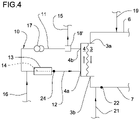
- FIG. 4 shows the portion of FIG. 2 according to another variant
- FIG. 5 shows a flow chart of a procedure for blood warming control
- FIG. 6 shows a flow chart of another procedure for blood warming control
- FIG. 7 shows a flow chart of another procedure for blood warming control.
- FIG. 1 shows a schematic representation of an extracorporeal blood treatment apparatus 1 .
- the apparatus 1 comprises one blood treatment device 2 , for example a hemofilter, a hemodiafilter, a plasmafilter, a dialysis filter or other unit suitable for processing the blood taken from a patient P.
- one blood treatment device 2 for example a hemofilter, a hemodiafilter, a plasmafilter, a dialysis filter or other unit suitable for processing the blood taken from a patient P.
- the blood treatment device 2 has a first compartment or blood chamber 3 and a second compartment or fluid chamber 4 separated from one another by a semipermeable membrane 5 .
- a blood withdrawal line 6 is connected to an inlet port 3 a of the blood chamber 3 and is configured, in an operative condition of connection to the patient P, to remove blood from a vascular access device inserted, for example in a fistula on the patient P.
- a blood return line 7 connected to an outlet port 3 b of the blood chamber 3 is configured to receive treated blood from the treatment unit 2 and to return the treated blood, e.g. to a further vascular access also connected to the fistula of the patient P.
- vascular access device various configurations for the vascular access device may be envisaged: for example, typical access devices include a needle or catheter inserted into a vascular access which may be a fistula, a graft or a central (e.g. jugular vein) or peripheral vein (femoral vein) and so on.
- a vascular access which may be a fistula, a graft or a central (e.g. jugular vein) or peripheral vein (femoral vein) and so on.
- the blood withdrawal line 6 and the blood return line 7 are part of an extracorporeal blood circuit of the apparatus 1 .
- the extracorporeal blood circuit 6 , 7 and the treatment unit 2 are usually disposable parts which are loaded onto a frame of a blood treatment machine, not shown.
- the apparatus 1 comprises at least a first actuator, in the present example a blood pump 8 , which is part of said machine and operates at the blood withdrawal line 6 , to cause movement of the blood removed from the patient P from a first end of the withdrawal line 6 connected to the patient P to the blood chamber 3 .
- the blood pump 8 is, for example, a peristaltic pump, as shown in FIG. 1 , which acts on a respective pump section of the withdrawal line 6 . When rotated, e.g., clockwise, the blood pump 8 causes a flow of blood along the blood withdrawal line 6 towards the blood chamber 3 (see the arrows in FIG. 1 indicative of the blood flow along the blood withdrawal line 6 ).
- upstream and downstream may be used with reference to the relative positions taken by components belonging to or operating on the extracorporeal blood circuit. These terms are to be understood with reference to a blood flow direction from the first end of the blood withdrawal line 6 connected to the patient P towards the blood chamber 3 and then from the blood chamber 3 towards a second end of the blood return line 7 connected to the vascular access of the patient P.
- the apparatus 1 may further comprise an air trapping device 9 operating on the blood return line 7 (the air trapping device 9 is a venous deaeration chamber).
- the air trapping device 9 is placed online in the blood return line 7 .
- a first section of the blood return line 7 puts in fluid communication the outlet port 3 b of the blood chamber 3 with the air trapping device 9 and a second section of the blood return line 7 puts in fluid communication the air trapping device 9 with the patient P.
- the blood coming from the blood chamber 3 of the treatment device 2 enters and exits the air trapping device 9 before reaching the patient P.
- the apparatus 1 further comprises a closed fluid line 10 connected to an inlet port 4 a of the fluid chamber 4 and to an outlet port 4 b of said fluid chamber 4 .
- the closed fluid line 10 comprises a first section 11 connected to the outlet port 4 b and departing from the fluid chamber 4 and a second section 12 connected to the inlet port 4 a and joined to said fluid chamber 4 .
- the second section 11 develops uninterrupted from the first section 11 and, in the attached non limiting figures, the closed fluid line 10 is “U” shaped.
- the closed fluid line 10 together with the fluid chamber 4 forms a recirculation loop for at least part of the fluid flowing through the fluid chamber 4 .
- a fluid warming device 13 is coupled to the closed fluid line 10 .
- the fluid warming device 13 is schematically represented in the annexed figures.
- the fluid warming device 13 is associated with the apparatus 1 to form an assembly which is structured to treat fluid and keep fluid within predetermined desired temperature boundaries.
- the fluid warming device 13 may comprise a warmer provided with a heating unit which cooperates with a heated section 14 of the closed fluid line 10 .
- This heated section 14 may be a tube or a bag or a cassette part of the closed fluid line 10 or part of the warmer itself.
- the fluid warming device 13 may be an independent device (e.g. a stand alone unit physically separated from the apparatus 1 ) cooperating with the apparatus 1 and—in particular—warming the heated section 14 of the closed fluid line 10 .
- the fluid warming device 13 may be a component of the apparatus 1 .
- the fluid warming device 13 is not an independent stand alone unit, but rather part of the apparatus 1 .
- the heating unit has heating elements (e.g. electric impedances, infrared emitters or other types of heating elements) configured to heat the corresponding heated section 14 of the closed fluid line 10 .
- the apparatus 1 of FIG. 1 further comprises one fluid evacuation line 15 connected with an outlet port 4 b of the fluid chamber 4 through the first section 11 of the closed fluid line 10 such as to receive at least part of a filtered waste fluid through the semipermeable membrane 5 .
- the fluid evacuation line 15 receives such filtered waste fluid coming from the fluid chamber 4 of the treatment device 2 , for example, comprising used dialysis liquid and/or liquid ultra-filtered through the membrane 5 .
- the fluid evacuation line 15 leads to a receiving element, not shown, for example having a collection bag or a drainage pipe for the waste fluid.
- One or more dialysate pumps, not shown, may operate on the evacuation line 15 .
- a dialysis line 16 is also present, for supplying a fresh treatment fluid into the closed fluid line 10 and then into the inlet port 4 a of the fluid chamber 4 .
- the presence of this dialysis line 16 is not strictly necessary since, in the absence of the dialysis line 16 , the apparatus 1 is still able to perform treatments such as ultrafiltration, hemofiltration or plasma-filtration.
- a fluid flow intercept device may be used, not shown, to selectively allow or inhibit fluid passage through the dialysis line 16 , depending on whether or not a purification by diffusive effect is to be performed inside the treatment device 2 .
- the dialysis line 16 if present, is typically equipped with a dialysis pump, not shown, and is able to receive a fresh fluid from a module, for example a bag or on-line preparation section of dialysis fluid, and to send such a fluid to the inlet port 4 a of the fluid chamber 4 .
- the fluid evacuation line 10 , the dialysis line 16 , the closed fluid line 10 and the fluid chamber 4 are part of a treatment fluid circuit.
- a recirculation pump 17 is coupled to the closed fluid line 10 and operates to cause movement of the fluid in said closed fluid line 10 from the outlet port 4 b of the fluid chamber 4 through the first section 11 and through the second section 12 of the closed fluid line 10 to the inlet port 4 a of the fluid chamber 4 and, inside said fluid chamber 4 , from the inlet port 4 a towards the outlet port 4 b.
- the recirculation pump 17 is, for example, a peristaltic pump which acts on a respective pump section of the closed fluid line 10 . When rotated, e.g., clockwise, the recirculation pump 17 causes a flow of fluid counterclockwise in recirculation loop (see arrows in FIG. 1 ).
- the recirculation loop on the fluid circuit allows to constantly maintain a significant fluid flow rate in the fluid chamber 4 of the blood treatment device 2 .
- the fluid evacuation line 15 is connected to the closed fluid line 10 between the outlet port 4 b and said recirculation pump 17 .
- the fluid warming device 13 is placed between the recirculation pump 17 and the inlet port 4 a.
- the dialysis line 16 is connected to the closed fluid line 10 between the fluid warming device 13 and the recirculation pump 17 .
- an air trap 18 is placed on the closed fluid line 10 to manage air generated by degassing due to fluid warming.
- the apparatus 1 as shown comprises an infusion circuit comprising one or more infusion lines of a replacement fluid.
- a pre-infusion line 19 is connected to the blood withdrawal line 6 between the blood pump 8 and the inlet port 3 a of the blood chamber 3 .
- a pre pump infusion line 20 is connected to the blood withdrawal line 6 upstream of the blood pump 8 , between said blood pump 8 and the vascular access device inserted in the fistula on the patient P.
- a post-infusion line 21 is connected to the blood return line 7 upstream of the air trapping device 9 .
- Each of the pre- and/or post-infusion lines 19 , 20 , 21 may be provided with a respective pump.
- the pre- and/or post-infusion lines 19 , 20 , 21 may be supplied by fluid coming from bags or directly by infusion fluid prepared on-line.
- the apparatus 1 comprises a blood temperature sensor 22 operative on the extracorporeal blood circuit and configured to sense a blood temperature.
- the blood temperature sensor 22 is placed on the blood return line 7 .
- the blood temperature sensor 22 is placed so close to the outlet port 3 b of the blood chamber 3 to sense the temperature of the blood coming out of the blood chamber 3 .
- the blood temperature sensor 22 is placed downstream of the post infusion line 21 , between said post infusion line 21 and the air trapping device 9 .
- the post infusion line 21 is connected between the outlet port 3 b of the blood chamber 3 and the blood temperature sensor 22 .
- the apparatus 1 comprises an auxiliary blood temperature sensor 23 operative on the withdrawal line 6 close to the patient P to sense the temperature of the blood withdrawn from the patient P.
- the pre-infusion line 19 is connected downstream of the auxiliary blood temperature sensor 23 .
- the apparatus 1 comprises a fluid temperature sensor 24 operative on the closed fluid line 10 and configured to sense a fluid temperature in the closed fluid line 10 .
- the fluid temperature sensor 24 of FIG. 1 is placed so close to an outlet of the fluid warming device 13 to sense the temperature of the fluid coming out of said fluid warming device 13 .
- said fluid temperature sensor 24 may also be part of the fluid warming device 13 , embedded in a frame or casing of the fluid warming device 13 .
- the apparatus 1 comprises a control unit 25 which may comprise a digital processor (CPU) and memory (or memories), an analog circuit, or a combination thereof.
- the control unit 25 is connected to the blood pump 8 and may be configured to control the blood pump 8 based, by way of example, on a set blood flow rate.
- the control unit 25 of the apparatus 1 may also be configured to control the flow rate of dialysis fluid through the dialysis line 16 , of evacuation fluid through the evacuation line 15 , of infusion fluid/s through pre-infusion line 19 , the pre pump infusion line 20 and post-infusion line 21 .
- the control unit 25 is also connected to the recirculation pump 17 and to the fluid warming device 13 and it is configured to control said recirculation pump 17 and said fluid warming device 13 in order to adjust the temperature of blood in the blood circuit.
- control unit 25 is also connected to the blood temperature sensor 22 , to the auxiliary blood temperature sensor 23 and to the fluid temperature sensor 24 .
- warming of blood is performed through warming of fluid in the recirculation loop.
- a preset/target blood temperature Tbp at the outlet 3 a of the blood chamber 3 is entered into the control unit 25 or previously saved in the memory of the control unit 25 .
- Said preset blood temperature Tbp may be the body temperature or close to the body temperature.
- Said preset blood temperature Tbp may of about 37° C.
- said preset blood temperature Tbp may be higher than the body temperature, for example of about 38° C.
- Fluid flow rate Qr in the recirculation loop as well as fluid temperature Tf at the outlet of the warming device are modulated to reach and keep the preset/target blood temperature Tbp at the outlet 3 a of the blood chamber 3 .
- the control unit 25 continuously receives from the blood temperature sensor 22 a signal correlated to the blood temperature Tb at the outlet 3 b of the blood chamber 3 .
- the control unit 25 controls at least one of the fluid warming device 13 and the recirculation pump 17 to bring and keep the measured blood temperature Tb equal to or close to the preset blood temperature Tbp.
- the fluid flow rate Qr in the recirculation loop 10 is fixed to a preset fluid flow rate Qrp, by maintaining a fixed rotational speed of the recirculation pump 17 , and the fluid temperature Tf at the outlet of the warming device 13 is regulated in order to bring and keep the measured blood temperature Tb at the outlet 3 a of the blood chamber 3 equal to or at least close to the preset blood temperature Tbp (flow chart of FIG. 5 ).
- the control unit 25 may regulate a power of the fluid warming device 13 to bring and keep the measured blood temperature Tb equal to or at least close to the preset blood temperature Tbp.
- the control unit 25 receives from the fluid temperature sensor 24 a signal correlated to the fluid temperature Tf at the outlet of the warming device 13 .
- a maximum fluid temperature Tfmax at the outlet of the warming device 13 is set (by way of example to 42° C.)
- the control unit 25 controls the power of the fluid warming device 13 so that the fluid temperature Tf does not exceed said maximum fluid temperature Tfmax.
- the following table 1 shows the outcome in the case of the recirculation loop of FIG. 1 is operated at a fixed fluid flow rate Qr and the fluid temperature Tf at the outlet of the warming device 13 is adjusted as to deliver the desired/preset outlet blood temperature Tbp.
- Qb (ml/min) is the blood flow rate in the blood circuit.
- Qd (ml/min) is the flow rate of dialysate in the dialysis line 16 .
- a fluid temperature Tf at the outlet of the warming device 13 is fixed to a preset fluid temperature Tfp, which may be the maximum fluid temperature Tfmax, by controlling the power of the warming device 13 .
- the fluid flow rate Qr in the recirculation loop is regulated in order to bring and keep the measured blood temperature Tb at the outlet 3 b of the blood chamber 3 equal to or at least close to the preset blood temperature Tbp (flow chart of FIG. 6 ).
- the control unit 25 may regulate the rotational speed of the recirculation pump 17 to bring and keep the measured blood temperature Tb equal to or at least close to the preset blood temperature Tbp.
- Table 2 shows that the fluid flow rate Qr is minimised by having the warming device 13 operating at its maximum set point when non-zero fluid flow rate Qr is used to get the desired preset blood temperature Tbp. In these conditions, much lower fluid flow rates Qr than the 66 ml/min of table 1 may be used as soon as dialysate flow is not zero.
- control unit 25 may operate as follows (flow chart of FIG. 7 ):
- dialyzer clearance is defined as the volume of plasma or blood from which a given substance has been removed completely in a given time period.
- the dialyzer clearance of a substance depends on four factors: 1. Surface area of the dialyzer. 2. Blood flow rate. 3. Dialysate flow rate. 4. Permeability of that substance with respect to the dialyzer membrane.
- the extracorporeal blood treatment apparatus of FIG. 1 may also be configured to perform a degassing procedure of the membrane 5 (filter) of the blood treatment device 2 to allow for periodical removal of air bubbles generated or trapped inside said membrane 5 .
- the control unit 25 controls the recirculation pump 17 to reverse the fluid flow in the recirculation loop. Instead of being moved, in the closed fluid line 10 , from the outlet port 4 b to the inlet port 4 a of the fluid chamber 4 , the fluid is moved from the inlet port 4 a towards the outlet port 4 b with a maximum fluid flow rate of about 300 ml/min and for a time period of about 1 min. In this way, air bubbles from the membrane 5 are moved into the air trap 18 and then air accumulated in the air trap 18 may be removed through a service line, not shown.
- the removal through the service line may be fully automatic, if the air trap 18 is equipped with a level sensor and the service line is connected to a pump, or manually under the supervision of the operator.
- air trapped in the air trap 18 may be vented ‘passively’ through a hydrophobic membrane, provided that the absolute pressure is kept positive in the recirculation loop. This may require the addition of a pressure drop in the recirculation loop.
- the extracorporeal blood treatment apparatus of FIG. 2 differs from the apparatus of FIG. 1 in that the post infusion line 21 is operatively coupled to the warming device 13 , so that said infusion fluid is heated before reaching the return line 7 of the blood circuit.
- FIG. 2 shows that the post infusion line 21 passes through the fluid warming device 13 and then is connected to the blood circuit.
- the pre infusion line 19 and the pre-pump infusion line 20 may be heated by the fluid warming device 13 .
- the fluid warming device 13 comprises a first portion operative on the closed fluid line 10 and at least a second portion operative on said at least one among the post infusion line 21 , the pre infusion line 19 and the pre-pump infusion line 20 .
- Each portion of the warming device 13 may comprise a respective heating unit which cooperates with a heated section 26 of the respective infusion line 19 , 20 , 21 .
- Each heating unit may be controlled separately by the control unit 25 in order to heat in different manner the closed fluid line 10 and each of the infusion line 19 , 20 , 21 .
- This configuration allows for both cheaper and easier operation of the system.
- the combined warming device 13 may combine both hardware components (display, user interface commands, power supply, etc.) in one single device, as well as the disposable circuit components in one single article.
- the extracorporeal blood treatment apparatus of FIG. 3 differs from the apparatus of FIG. 1 in that a heat exchanger 27 is placed on the closed fluid line 10 between the fluid warming device 13 and the inlet port 4 b of the fluid chamber 4 .
- a heating section 28 of the closed fluid line 10 passes through the heat exchanger 27 .
- a heated section 26 of the post infusion line 21 passes through the heat exchanger 27 and then it is connected to the blood circuit.
- the flow of fluid in the heating section 28 of the closed fluid line 10 and the flow of infusion fluid in the heated section 26 of the post infusion line 21 flows in opposite directions (the heat exchanger is of counter-current type).
- the fluid in the heating section 28 of the closed fluid line 10 has just been heated in the warming device 13 and supplies heat to the infusion fluid in the heated section 26 .
- the pre infusion line 19 and the pre-pump infusion line 20 may be heated in the heat exchanger 27 .
- the infusion fluid/s are heated exploiting the same warming device 13 which heats the recirculation loop.
- the extracorporeal blood treatment apparatus of FIG. 4 differs from the apparatus of FIG. 1 in that the air trap 18 ′ is placed between the recirculation pump 17 and the outlet 4 b of the fluid chamber 4 instead of between the warming device 13 and the inlet 4 a of the fluid chamber 4 . Furthermore, the evacuation line 15 departs from said air trap 18 ′.
- the air trap 18 ′ is located at the outlet port 4 b of the fluid chamber 4 and the evacuation line 15 is used as to remove air bubbles simultaneously to the ‘waste’ fluid.
- the degassing procedure simply consists in running maximum recirculation flow rate (300 ml/min) for a short time period (typically less than 1 min).
- dialysis line 16 may be connected to the recirculation loop between the evacuation line 15 and the recirculation pump 17 .
- a fluid flow rate in the recirculation loop is equal to or greater than a dialysate flow rate in the dialysis line 16 .
- the dialysis line 16 is connected downstream of the warming device 13 .
- the dialysis line 16 is not present. With respect to FIG. 1 the dialysis line 16 simply disappears.
Landscapes
- Health & Medical Sciences (AREA)
- Heart & Thoracic Surgery (AREA)
- Vascular Medicine (AREA)
- Life Sciences & Earth Sciences (AREA)
- Engineering & Computer Science (AREA)
- Anesthesiology (AREA)
- Biomedical Technology (AREA)
- Hematology (AREA)
- Animal Behavior & Ethology (AREA)
- General Health & Medical Sciences (AREA)
- Public Health (AREA)
- Veterinary Medicine (AREA)
- Urology & Nephrology (AREA)
- Emergency Medicine (AREA)
- Cardiology (AREA)
- External Artificial Organs (AREA)
Applications Claiming Priority (4)
| Application Number | Priority Date | Filing Date | Title |
|---|---|---|---|
| EP16181664.0 | 2016-07-28 | ||
| EP16181664.0A EP3275473B1 (de) | 2016-07-28 | 2016-07-28 | Vorrichtung zur exrakorporalen behandlung von blut |
| EP16181664 | 2016-07-28 | ||
| PCT/EP2017/068983 WO2018019926A1 (en) | 2016-07-28 | 2017-07-27 | Apparatus for extracorporeal treatment of blood |
Related Parent Applications (1)
| Application Number | Title | Priority Date | Filing Date |
|---|---|---|---|
| PCT/EP2017/068983 A-371-Of-International WO2018019926A1 (en) | 2016-07-28 | 2017-07-27 | Apparatus for extracorporeal treatment of blood |
Related Child Applications (1)
| Application Number | Title | Priority Date | Filing Date |
|---|---|---|---|
| US17/873,561 Continuation US12364796B2 (en) | 2016-07-28 | 2022-07-26 | Apparatus for extracorporeal treatment of blood |
Publications (2)
| Publication Number | Publication Date |
|---|---|
| US20190160216A1 US20190160216A1 (en) | 2019-05-30 |
| US11419968B2 true US11419968B2 (en) | 2022-08-23 |
Family
ID=56551321
Family Applications (2)
| Application Number | Title | Priority Date | Filing Date |
|---|---|---|---|
| US16/321,115 Active 2039-12-23 US11419968B2 (en) | 2016-07-28 | 2017-07-27 | Apparatus for extracorporeal treatment of blood |
| US17/873,561 Active 2037-07-27 US12364796B2 (en) | 2016-07-28 | 2022-07-26 | Apparatus for extracorporeal treatment of blood |
Family Applications After (1)
| Application Number | Title | Priority Date | Filing Date |
|---|---|---|---|
| US17/873,561 Active 2037-07-27 US12364796B2 (en) | 2016-07-28 | 2022-07-26 | Apparatus for extracorporeal treatment of blood |
Country Status (3)
| Country | Link |
|---|---|
| US (2) | US11419968B2 (de) |
| EP (2) | EP3275473B1 (de) |
| WO (1) | WO2018019926A1 (de) |
Families Citing this family (5)
| Publication number | Priority date | Publication date | Assignee | Title |
|---|---|---|---|---|
| EP3637218B1 (de) * | 2018-10-10 | 2024-09-11 | Gambro Lundia AB | Fluiderwärmungsvorrichtung für eine extrakorporale blutbehandlungsvorrichtung und verfahren zum erfassen der fluidtemperatur am auslass einer fluiderwärmungsvorrichtung für eine extrakorporale blutbehandlungsvorrichtung |
| US12569609B2 (en) | 2019-11-19 | 2026-03-10 | Irasun Gmbh | Temperature management system for patients during stationary and mobile ECLS/ECMO therapy |
| DE102021133630A1 (de) * | 2021-12-17 | 2023-06-22 | Fresenius Medical Care Deutschland Gmbh | Blutbehandlungsvorrichtung mit Heizungsregelung |
| US20230211062A1 (en) * | 2022-01-04 | 2023-07-06 | King Faisal University | Hemodialysis system with dialysate recycling |
| CN119055868A (zh) * | 2023-06-02 | 2024-12-03 | 甘布罗伦迪亚股份公司 | 体外血液治疗管道组件和装置 |
Citations (4)
| Publication number | Priority date | Publication date | Assignee | Title |
|---|---|---|---|---|
| US4894164A (en) | 1986-10-30 | 1990-01-16 | Fresenius Ag | Apparatus for treating blood in an extracorporeal circuit |
| US5247434A (en) | 1991-04-19 | 1993-09-21 | Althin Medical, Inc. | Method and apparatus for kidney dialysis |
| DE29518797U1 (de) | 1995-08-25 | 1996-09-26 | Tsolkas, Panagiotis, 21335 Lüneburg | Apparatur zur Ganzkörperhyperthermie-Behandlung |
| EP2995329A1 (de) | 2014-09-15 | 2016-03-16 | Gambro Lundia AB | Vorrichtung zur extrakorporalen Behandlung von Blut und Steuerungsverfahren einer Bluterwärmungsvorrichtung in einer extrakorporellen Blutbehändlungsvorrichtung |
Family Cites Families (8)
| Publication number | Priority date | Publication date | Assignee | Title |
|---|---|---|---|---|
| US3669880A (en) | 1969-06-30 | 1972-06-13 | Cci Aerospace Corp | Recirculation dialysate system for use with an artificial kidney machine |
| US3809241A (en) | 1973-02-23 | 1974-05-07 | Electro Sys Eng Inc | Self-container kidney dialysis apparatus |
| US3878095A (en) * | 1974-05-02 | 1975-04-15 | Advanced Medical Sciences Inc | Dialysis apparatus |
| US4079007A (en) | 1976-09-07 | 1978-03-14 | Union Carbide Corporation | Hemodialysis system with modular dialysate manifold assembly |
| US5591344A (en) | 1995-02-13 | 1997-01-07 | Aksys, Ltd. | Hot water disinfection of dialysis machines, including the extracorporeal circuit thereof |
| US20090120864A1 (en) * | 2007-10-05 | 2009-05-14 | Barry Neil Fulkerson | Wearable dialysis methods and devices |
| CN101986776B (zh) | 2007-10-12 | 2015-04-01 | 德卡产品有限公司 | 血液透析装置及方法 |
| US10010663B2 (en) | 2013-02-01 | 2018-07-03 | Medtronic, Inc. | Fluid circuit for delivery of renal replacement therapies |
-
2016
- 2016-07-28 EP EP16181664.0A patent/EP3275473B1/de active Active
-
2017
- 2017-07-27 EP EP17746067.2A patent/EP3490633B1/de active Active
- 2017-07-27 US US16/321,115 patent/US11419968B2/en active Active
- 2017-07-27 WO PCT/EP2017/068983 patent/WO2018019926A1/en not_active Ceased
-
2022
- 2022-07-26 US US17/873,561 patent/US12364796B2/en active Active
Patent Citations (4)
| Publication number | Priority date | Publication date | Assignee | Title |
|---|---|---|---|---|
| US4894164A (en) | 1986-10-30 | 1990-01-16 | Fresenius Ag | Apparatus for treating blood in an extracorporeal circuit |
| US5247434A (en) | 1991-04-19 | 1993-09-21 | Althin Medical, Inc. | Method and apparatus for kidney dialysis |
| DE29518797U1 (de) | 1995-08-25 | 1996-09-26 | Tsolkas, Panagiotis, 21335 Lüneburg | Apparatur zur Ganzkörperhyperthermie-Behandlung |
| EP2995329A1 (de) | 2014-09-15 | 2016-03-16 | Gambro Lundia AB | Vorrichtung zur extrakorporalen Behandlung von Blut und Steuerungsverfahren einer Bluterwärmungsvorrichtung in einer extrakorporellen Blutbehändlungsvorrichtung |
Non-Patent Citations (1)
| Title |
|---|
| International Search Report and Written Opinion for International Application No. PCT/EP2017/068983; dated Oct. 11, 2017; (13 pages). |
Also Published As
| Publication number | Publication date |
|---|---|
| EP3490633B1 (de) | 2020-04-29 |
| US20220355008A1 (en) | 2022-11-10 |
| EP3275473B1 (de) | 2018-12-19 |
| US12364796B2 (en) | 2025-07-22 |
| EP3275473A1 (de) | 2018-01-31 |
| EP3490633A1 (de) | 2019-06-05 |
| US20190160216A1 (en) | 2019-05-30 |
| WO2018019926A1 (en) | 2018-02-01 |
Similar Documents
| Publication | Publication Date | Title |
|---|---|---|
| US12364796B2 (en) | Apparatus for extracorporeal treatment of blood | |
| US12070539B2 (en) | Extracorporeal blood treatment method | |
| US6716356B2 (en) | Thermally enhanced dialysis/diafiltration system | |
| AU2014320591B2 (en) | Apparatus for extracorporeal treatment of blood and method of control of a blood-warming device in an extracorporeal blood treatment apparatus | |
| US11857715B2 (en) | Extracorporeal blood treatment apparatus | |
| CN115087472A (zh) | 用于产生用于腹膜透析的流体的系统和方法 | |
| JP7317008B2 (ja) | 二酸化炭素生成及びプライムを有する透析システム | |
| CN111867649B (zh) | 具有局部消毒的透析系统 | |
| US11890401B2 (en) | Dialysis machines and methods of disinfecting a dialysis machine | |
| JP2026502241A (ja) | 体外血液治療装置における血液再循環の使い捨てセット、装置および手順 |
Legal Events
| Date | Code | Title | Description |
|---|---|---|---|
| FEPP | Fee payment procedure |
Free format text: ENTITY STATUS SET TO UNDISCOUNTED (ORIGINAL EVENT CODE: BIG.); ENTITY STATUS OF PATENT OWNER: LARGE ENTITY |
|
| AS | Assignment |
Owner name: GAMBRO LUNDIA AB, SWEDEN Free format text: ASSIGNMENT OF ASSIGNORS INTEREST;ASSIGNOR:GAMBRO INDUSTRIES;REEL/FRAME:048437/0423 Effective date: 20131009 Owner name: GAMBRO INDUSTRIES, FRANCE Free format text: ASSIGNMENT OF ASSIGNORS INTEREST;ASSIGNOR:POUCHOULIN, DOMINIQUE;REEL/FRAME:048437/0354 Effective date: 20131009 |
|
| STPP | Information on status: patent application and granting procedure in general |
Free format text: DOCKETED NEW CASE - READY FOR EXAMINATION |
|
| STPP | Information on status: patent application and granting procedure in general |
Free format text: NOTICE OF ALLOWANCE MAILED -- APPLICATION RECEIVED IN OFFICE OF PUBLICATIONS |
|
| STPP | Information on status: patent application and granting procedure in general |
Free format text: PUBLICATIONS -- ISSUE FEE PAYMENT VERIFIED |
|
| STCF | Information on status: patent grant |
Free format text: PATENTED CASE |
|
| MAFP | Maintenance fee payment |
Free format text: PAYMENT OF MAINTENANCE FEE, 4TH YEAR, LARGE ENTITY (ORIGINAL EVENT CODE: M1551); ENTITY STATUS OF PATENT OWNER: LARGE ENTITY Year of fee payment: 4 |