US11603775B2 - Removable pin on a turbomachine nozzle - Google Patents
Removable pin on a turbomachine nozzle Download PDFInfo
- Publication number
- US11603775B2 US11603775B2 US17/604,519 US202017604519A US11603775B2 US 11603775 B2 US11603775 B2 US 11603775B2 US 202017604519 A US202017604519 A US 202017604519A US 11603775 B2 US11603775 B2 US 11603775B2
- Authority
- US
- United States
- Prior art keywords
- head
- abutment
- casing
- flange
- distributor
- Prior art date
- Legal status (The legal status is an assumption and is not a legal conclusion. Google has not performed a legal analysis and makes no representation as to the accuracy of the status listed.)
- Active, expires
Links
- 238000000034 method Methods 0.000 claims description 6
- 238000002485 combustion reaction Methods 0.000 description 5
- 230000006378 damage Effects 0.000 description 3
- 238000011144 upstream manufacturing Methods 0.000 description 2
- 208000027418 Wounds and injury Diseases 0.000 description 1
- 238000006243 chemical reaction Methods 0.000 description 1
- 238000010276 construction Methods 0.000 description 1
- 230000008878 coupling Effects 0.000 description 1
- 238000010168 coupling process Methods 0.000 description 1
- 238000005859 coupling reaction Methods 0.000 description 1
- 208000014674 injury Diseases 0.000 description 1
- 238000007689 inspection Methods 0.000 description 1
- 238000012423 maintenance Methods 0.000 description 1
- 230000014759 maintenance of location Effects 0.000 description 1
- 238000007789 sealing Methods 0.000 description 1
- 238000000926 separation method Methods 0.000 description 1
- 238000003466 welding Methods 0.000 description 1
Images



Classifications
-
- F—MECHANICAL ENGINEERING; LIGHTING; HEATING; WEAPONS; BLASTING
- F01—MACHINES OR ENGINES IN GENERAL; ENGINE PLANTS IN GENERAL; STEAM ENGINES
- F01D—NON-POSITIVE DISPLACEMENT MACHINES OR ENGINES, e.g. STEAM TURBINES
- F01D25/00—Component parts, details, or accessories, not provided for in, or of interest apart from, other groups
- F01D25/24—Casings; Casing parts, e.g. diaphragms, casing fastenings
-
- F—MECHANICAL ENGINEERING; LIGHTING; HEATING; WEAPONS; BLASTING
- F01—MACHINES OR ENGINES IN GENERAL; ENGINE PLANTS IN GENERAL; STEAM ENGINES
- F01D—NON-POSITIVE DISPLACEMENT MACHINES OR ENGINES, e.g. STEAM TURBINES
- F01D9/00—Stators
- F01D9/02—Nozzles; Nozzle boxes; Stator blades; Guide conduits, e.g. individual nozzles
- F01D9/04—Nozzles; Nozzle boxes; Stator blades; Guide conduits, e.g. individual nozzles forming ring or sector
- F01D9/042—Nozzles; Nozzle boxes; Stator blades; Guide conduits, e.g. individual nozzles forming ring or sector fixing blades to stators
-
- F—MECHANICAL ENGINEERING; LIGHTING; HEATING; WEAPONS; BLASTING
- F01—MACHINES OR ENGINES IN GENERAL; ENGINE PLANTS IN GENERAL; STEAM ENGINES
- F01D—NON-POSITIVE DISPLACEMENT MACHINES OR ENGINES, e.g. STEAM TURBINES
- F01D25/00—Component parts, details, or accessories, not provided for in, or of interest apart from, other groups
- F01D25/24—Casings; Casing parts, e.g. diaphragms, casing fastenings
- F01D25/246—Fastening of diaphragms or stator-rings
-
- F—MECHANICAL ENGINEERING; LIGHTING; HEATING; WEAPONS; BLASTING
- F01—MACHINES OR ENGINES IN GENERAL; ENGINE PLANTS IN GENERAL; STEAM ENGINES
- F01D—NON-POSITIVE DISPLACEMENT MACHINES OR ENGINES, e.g. STEAM TURBINES
- F01D5/00—Blades; Blade-carrying members; Heating, heat-insulating, cooling or antivibration means on the blades or the members
- F01D5/02—Blade-carrying members, e.g. rotors
- F01D5/08—Heating, heat-insulating or cooling means
- F01D5/081—Cooling fluid being directed on the side of the rotor disc or at the roots of the blades
- F01D5/082—Cooling fluid being directed on the side of the rotor disc or at the roots of the blades on the side of the rotor disc
-
- F—MECHANICAL ENGINEERING; LIGHTING; HEATING; WEAPONS; BLASTING
- F01—MACHINES OR ENGINES IN GENERAL; ENGINE PLANTS IN GENERAL; STEAM ENGINES
- F01D—NON-POSITIVE DISPLACEMENT MACHINES OR ENGINES, e.g. STEAM TURBINES
- F01D9/00—Stators
- F01D9/02—Nozzles; Nozzle boxes; Stator blades; Guide conduits, e.g. individual nozzles
- F01D9/04—Nozzles; Nozzle boxes; Stator blades; Guide conduits, e.g. individual nozzles forming ring or sector
-
- F—MECHANICAL ENGINEERING; LIGHTING; HEATING; WEAPONS; BLASTING
- F05—INDEXING SCHEMES RELATING TO ENGINES OR PUMPS IN VARIOUS SUBCLASSES OF CLASSES F01-F04
- F05D—INDEXING SCHEME FOR ASPECTS RELATING TO NON-POSITIVE-DISPLACEMENT MACHINES OR ENGINES, GAS-TURBINES OR JET-PROPULSION PLANTS
- F05D2230/00—Manufacture
- F05D2230/60—Assembly methods
- F05D2230/64—Assembly methods using positioning or alignment devices for aligning or centring, e.g. pins
-
- F—MECHANICAL ENGINEERING; LIGHTING; HEATING; WEAPONS; BLASTING
- F05—INDEXING SCHEMES RELATING TO ENGINES OR PUMPS IN VARIOUS SUBCLASSES OF CLASSES F01-F04
- F05D—INDEXING SCHEME FOR ASPECTS RELATING TO NON-POSITIVE-DISPLACEMENT MACHINES OR ENGINES, GAS-TURBINES OR JET-PROPULSION PLANTS
- F05D2250/00—Geometry
- F05D2250/10—Two-dimensional
- F05D2250/12—Two-dimensional rectangular
-
- F—MECHANICAL ENGINEERING; LIGHTING; HEATING; WEAPONS; BLASTING
- F05—INDEXING SCHEMES RELATING TO ENGINES OR PUMPS IN VARIOUS SUBCLASSES OF CLASSES F01-F04
- F05D—INDEXING SCHEME FOR ASPECTS RELATING TO NON-POSITIVE-DISPLACEMENT MACHINES OR ENGINES, GAS-TURBINES OR JET-PROPULSION PLANTS
- F05D2250/00—Geometry
- F05D2250/10—Two-dimensional
- F05D2250/13—Two-dimensional trapezoidal
- F05D2250/131—Two-dimensional trapezoidal polygonal
-
- F—MECHANICAL ENGINEERING; LIGHTING; HEATING; WEAPONS; BLASTING
- F05—INDEXING SCHEMES RELATING TO ENGINES OR PUMPS IN VARIOUS SUBCLASSES OF CLASSES F01-F04
- F05D—INDEXING SCHEME FOR ASPECTS RELATING TO NON-POSITIVE-DISPLACEMENT MACHINES OR ENGINES, GAS-TURBINES OR JET-PROPULSION PLANTS
- F05D2260/00—Function
- F05D2260/30—Retaining components in desired mutual position
Definitions
- the invention relates to a turbomachine assembly. More specifically, the invention relates to the architecture of a turbine and in particular to the mounting support for a distributor in a high-pressure turbine.
- FIG. 1 discloses in FIG. 1 a high-pressure turbine distributor, mounted on an annular casing.
- the distributor comprises a platform supporting an annular row of fixed vanes.
- An annular row of pins (noted 22 ) allows a circumferential and radial positioning of a platform flange to a casing flange.
- An abutment (marked 21 ) completes the connection between the distributor and the casing, the abutment holding the flanges axially against one another.
- the abutment is radially supported on a support ring (noted 3 ).
- removing the distributor requires disassembling the abutment, and disassembling the abutment can only be done by removing the support ring, fixed to the casing.
- the purpose of the invention is to propose a design for the coupling of the distributor and the high-pressure turbine casing which allows faster maintenance operations, and in particular to avoid disassembling the support ring and the casing.
- the invention relates to a turbomachine assembly
- a turbomachine assembly comprising: a turbine distributor comprising an annular platform, an inner radial flange extending radially inwardly from the platform, and one or more blades extending radially outwardly from the platform; a casing comprising an outer radial flange; and an abutment providing axial retention of the outer radial flange in contact with the inner radial flange; characterized in that the abutment is constituted by a head and a body removably connected to the head.
- the assembly can comprise one or more of the following technical features, in any possible combination:
- the invention relates to a method of servicing a turbomachine, which is remarkable in that the turbomachine is according to the embodiment of the preceding paragraph and in that the method comprises, in this order: a step of removing the body of the abutment; and a step of removing the distributor, during which the head of the abutment remains engaged in the casing and the support ring remains fixed to the casing, the method furthermore in various instances comprising a step of reassembling the distributor and then a step of fastening the body of the abutment to the head of the abutment.
- the measures of the invention are interesting in that only a part of the abutment has to be disassembled from the casing to allow the disassembly of the distributor.
- the assembly of the casing and the support ring is thus preserved.
- the two parts of the abutment can be assembled by simple means such as quick-fixing.
- FIG. 1 describes an exemplary turbomachine according to various embodiments of the invention.
- FIG. 2 shows a partial cross-section of a known turbine.
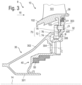
- FIG. 3 shows an exemplary partial cross-sectional view of a turbine according to various embodiments of the invention.
- FIG. 4 shows an exemplary embodiment of the abutment according to various embodiments of the invention.
- FIG. 5 shows a detail of the abutment, seen in the direction indicated as V:V in FIG. 4 , in accordance with various embodiments of the invention.
- the terms “internal” and “external” refer to positioning relative to the axis of rotation of an axial turbomachine which is also the axis of rotation of the turbine.
- the axial direction is the direction along the axis of rotation of the turbomachine.
- the radial direction is perpendicular to the axis of rotation. Upstream and downstream are in reference to the main flow direction of the flow in the turbomachine.
- integrated is understood to mean rotationally integral, and in particular rigidly linked.
- the term “monobloc” is equivalent to “made from the same material” and designates different elements made from the same block of material, as opposed to “attached”, which means that one element is attached to another element after these elements have been manufactured.
- the figures represent the elements in a schematic manner, in particular without all the assembly or sealing elements. some of the dimensions of the elements drawn, and in particular their radial thicknesses, are exaggerated in order to facilitate understanding of the figures.
- distributedor means a set of circumferentially adjacent angular sectors forming an annular row of stationary vanes, each of the angular sectors can have at least one, for example two or three stationary vanes.
- FIG. 1 shows a simplified representation of an axial turbomachine 2 .
- the turbomachine 2 comprises a low-pressure compressor 4 and a high-pressure compressor 6 , a combustion chamber 8 and one or more turbines 9 .
- the mechanical power of the turbine 9 transmitted to the rotor 12 sets in motion the two compressors 4 and 6 .
- These compressors have several rows of rotor blades associated with rows of stator blades. The rotation of the rotor around its axis of rotation 14 thus makes it possible to generate a flow of air and to progressively compress the latter up to the inlet of the combustion chambers 8 .
- a fan 16 is coupled to the rotor 12 and generates an air flow which divides into a primary flow 18 and a secondary flow 20 passing through an annular duct (partially shown) along the machine and then rejoining the primary flow at the turbine outlet.
- Reduction means such as an epicyclic gearbox 22 , can reduce the rotational speed of the fan and/or low-pressure compressor relative to the associated turbine.
- the secondary flow can be accelerated so as to generate a thrust reaction required for making an aircraft fly.
- the turbine(s) 9 comprise alternating rotating blades and fixed blades.
- the term “distributor” will be used in this application to refer to an assembly of fixed blades and their supporting platform.
- the platform can be a full ring or a circumferential segment (partial ring).
- the first distributor downstream of the combustion chambers 8 is indicated by the number 10 in FIG. 1 . It is followed by an impeller 11 .
- FIG. 2 is a cross-sectional view showing a turbine stage 9 according to a known construction.
- the turbine stage 9 consists of a distributor 10 and an impeller 11 .
- the impeller 11 comprises an annular row of moving blades 110 each mounted in a cell 111 of a disc 112 .
- the distributor 10 comprises an annular row of fixed vanes 101 connected by their inner ends (root) to an annular lower platform 102 .
- the platform 102 has a flange 103 extending radially inwardly. This flange 103 allows the blades 101 to be made integral with the fixed annular casing 30 .
- the blades 101 , 110 extend radially into the hot, high pressure air stream 18 .
- the casing 30 includes an inner spindle 301 , an outer spindle 302 , an outer radial flange 303 and an inner radial flange 304 .
- the spindles 301 , 302 are coaxial along the axis 14 .
- the radially outer flange 303 is in axial contact with the inner flange 103 , the flange 303 being downstream of the flange 103 .
- the flanges 103 , 303 are positioned and held radially and circumferentially to each other by means of pins 32 , angularly distributed about the axis 14 .
- the pins 32 extend axially through the flanges 103 , 303 .
- the pin 32 that is visible in the cross-section of FIG. 2 extends along an axis noted A which is parallel to the axis 14 .
- the flanges 103 , 303 are held axially against each other by an abutment 34 .
- This abutment extends radially along an axis noted B.
- the axes A and B are shown in FIG. 2 to facilitate understanding of the invention, but these axes are not in the same plane, the abutment 34 being circumferentially offset from the pins 32 .
- the abutment 34 extends through a hole 305 provided in the casing 30 .
- a seal 36 housed in the flange 303 prevents air leakage from the air passage 18 into the interior.
- the abutment 34 is radially supported by a support ring 40 .
- the support ring 40 is connected to the casing 30 at its inner flange 304 by a screw assembly (not shown) extending along the C-axis.
- the support ring 40 is also radially supported by the internal spindle 301 of the casing 30 .
- the support ring 40 can be supported on a lip 306 of the casing 30 .
- the support ring 40 is provided with an abradable layer 50 to ensure a seal by cooperating with lips 62 of a rotating flange 60 , integral with the impeller 11 .
- FIG. 2 illustrates the assembly in its assembled configuration.
- the abutment 34 can only be removed from the casing 30 after disassembly of the support ring 40 .
- the objective of the invention is to reduce the number of disassembly steps required to remove the distributor.
- FIG. 3 represents a partial cross-sectional view of an assembly according to the invention. Parts similar to the known assembly shown in FIG. 2 retain their reference numbers. The invention differs essentially from the known assembly in the design of the abutment.
- the abutment is referenced 70 . It comprises a head 72 and a body 78 .
- the head 72 includes an inner portion 74 and an outer portion 76 that extends through the opening 305 of the casing 30 .
- the inner portion 74 has a dimension (diameter if it is a cylinder or diagonal if it is a polygon) that is greater than the diameter of the orifice 305 so that the inner portion 74 does not penetrate the orifice 305 .
- the head 72 is supported via its inner portion 74 by the support ring 40 , attached to the casing 30 .
- the head 72 is detachably connected to the body 78 .
- the head 72 and the body 78 are reversibly separable from each other.
- the head does not pass through the casing. It is received in a housing provided for this purpose.
- the head is welded to the casing or mounted tightly in its casing, so as to remain integral with the casing when the body is dismantled.
- the body 78 is adapted to contact the flange 103 to prevent axial disengagement of the flanges 103 , 303 .
- the body radially overlaps the inner flange 103 .
- radial overlap it is meant that there exist geometric points of the body 78 that have identical radial coordinates as some geometric points of the flange 103 .
- the head 72 is at a radial distance from the internal flange 103 in order to allow, once the body 78 is removed, the axial sliding of the distributor 10 upstream (towards the left in FIG. 3 ).
- FIG. 4 illustrates an example of an embodiment of the abutment 70 .
- the head 72 includes a threaded bore 761 which a threaded portion 781 of the body 78 engages.
- the body 78 can have a portion helping grasping it for unscrewing purposes, such as a portion with a square section 782 .
- the body 78 and the outer portion 76 of the head 72 have generally axisymmetric shapes about the B axis.
- FIG. 4 also partially shows the lip 306 of the casing which is proximate to the inner portion 74 .
- FIG. 5 illustrates the inner portion 74 as viewed in the direction indicated as V:V in FIG. 4 , showing the substantially polygonal cross-section 741 of the inner portion 74 , which in this example is a square.
- the square 741 can have rounded corners 742 .
- the dotted line shows a position of the inner portion 74 in contact with the lip 306 .
- the inner portion 74 can pivot and come to rest on a surface so as to be stopped in rotation and allowing unscrewing of the body 78 without the inner portion 74 turning freely.
- the abutment surface is a surface of the lip 306 .
- rotation of the inner portion 74 can be stopped by the inner flange 304 of the casing or by a surface of the support ring 40 .
- the contact surface between the support ring 40 and the abutment 70 can also stop the head 72 in rotation: for example, the support ring 40 can be provided with slots and the inner portion 74 can be provided with grooves (radial to the axis B) which can engage the slots.
Landscapes
- Engineering & Computer Science (AREA)
- Mechanical Engineering (AREA)
- General Engineering & Computer Science (AREA)
- Turbine Rotor Nozzle Sealing (AREA)
Applications Claiming Priority (3)
| Application Number | Priority Date | Filing Date | Title |
|---|---|---|---|
| FR1905298A FR3096397B1 (fr) | 2019-05-21 | 2019-05-21 | Pion amovible sur distributeur de turbomachine |
| FR1905298 | 2019-05-21 | ||
| PCT/EP2020/061624 WO2020233947A1 (fr) | 2019-05-21 | 2020-04-27 | Pion amovible sur distributeur de turbomachine |
Publications (2)
| Publication Number | Publication Date |
|---|---|
| US20220195891A1 US20220195891A1 (en) | 2022-06-23 |
| US11603775B2 true US11603775B2 (en) | 2023-03-14 |
Family
ID=67384146
Family Applications (1)
| Application Number | Title | Priority Date | Filing Date |
|---|---|---|---|
| US17/604,519 Active 2040-06-11 US11603775B2 (en) | 2019-05-21 | 2020-04-27 | Removable pin on a turbomachine nozzle |
Country Status (5)
| Country | Link |
|---|---|
| US (1) | US11603775B2 (de) |
| EP (1) | EP3973146B1 (de) |
| CN (1) | CN113811669B (de) |
| FR (1) | FR3096397B1 (de) |
| WO (1) | WO2020233947A1 (de) |
Families Citing this family (2)
| Publication number | Priority date | Publication date | Assignee | Title |
|---|---|---|---|---|
| FR3117147B1 (fr) * | 2020-12-09 | 2022-10-28 | Safran Aircraft Engines | Ensemble statorique de turbine avec degré de liberté radial entre un distributeur et un anneau d’étanchéité |
| FR3163107A1 (fr) * | 2024-06-08 | 2025-12-12 | Safran Aircraft Engines | Organe de blocage pour un segment de distributeur monté dans un carter d’une turbomachine pour aéronef |
Citations (6)
| Publication number | Priority date | Publication date | Assignee | Title |
|---|---|---|---|---|
| US5201846A (en) * | 1991-11-29 | 1993-04-13 | General Electric Company | Low-pressure turbine heat shield |
| GB2309053A (en) | 1996-01-11 | 1997-07-16 | Snecma | Turbomachine guide stage assembly |
| FR2960591A1 (fr) | 2010-06-01 | 2011-12-02 | Snecma | Dispositif pour caler en rotation un segment de distributeur dans un carter de turbomachine ; pion antirotation |
| US20120082568A1 (en) * | 2010-10-04 | 2012-04-05 | Rolls-Royce Plc | Turbine disc cooling arrangement |
| US20150322796A1 (en) * | 2012-09-03 | 2015-11-12 | Snecma | Turbine rotor for a turbomachine |
| FR3066226A1 (fr) | 2017-05-10 | 2018-11-16 | Safran Aircraft Engines | Verrouillage anneau stator sous distributeur haute pression |
Family Cites Families (12)
| Publication number | Priority date | Publication date | Assignee | Title |
|---|---|---|---|---|
| GB715086A (en) * | 1953-02-06 | 1954-09-08 | Rolls Royce | Improvements relating to separable joints |
| US4883405A (en) * | 1987-11-13 | 1989-11-28 | The United States Of America As Represented By The Secretary Of The Air Force | Turbine nozzle mounting arrangement |
| US5441385A (en) * | 1993-12-13 | 1995-08-15 | Solar Turbines Incorporated | Turbine nozzle/nozzle support structure |
| US5848874A (en) * | 1997-05-13 | 1998-12-15 | United Technologies Corporation | Gas turbine stator vane assembly |
| JP2001082103A (ja) * | 1999-09-09 | 2001-03-27 | Toshiba Corp | 蒸気タービン用ノズルダイアフラム |
| RU2260700C2 (ru) * | 2003-11-24 | 2005-09-20 | Открытое акционерное общество "Авиадвигатель" | Сопловой аппарат турбины газотурбинного двигателя |
| FR2935428B1 (fr) * | 2008-08-26 | 2015-06-26 | Snecma | Aubage fixe de turbomachine a masse reduite et turbomachine comportant au moins un tel aubage fixe |
| FR2935429B1 (fr) * | 2008-08-26 | 2011-11-25 | Snecma | Aubage fixe de turbomachine a masse reduite et turbomachine comportant au moins un tel aubage fixe |
| CN202545489U (zh) * | 2012-04-16 | 2012-11-21 | 虞有华 | 多用途中空膨胀螺栓 |
| FR3022944B1 (fr) * | 2014-06-26 | 2020-02-14 | Safran Aircraft Engines | Ensemble rotatif pour turbomachine |
| DE102014214703A1 (de) * | 2014-07-25 | 2016-01-28 | Siemens Aktiengesellschaft | Vorrichtung zum Ausrichten eines Leitschaufelträgers zu einem Gehäuse einer Turbine |
| FR3062876B1 (fr) * | 2017-02-14 | 2021-03-12 | Safran Aircraft Engines | Compresseur haute pression pour turbomachine |
-
2019
- 2019-05-21 FR FR1905298A patent/FR3096397B1/fr active Active
-
2020
- 2020-04-27 CN CN202080034973.0A patent/CN113811669B/zh active Active
- 2020-04-27 US US17/604,519 patent/US11603775B2/en active Active
- 2020-04-27 WO PCT/EP2020/061624 patent/WO2020233947A1/fr not_active Ceased
- 2020-04-27 EP EP20720100.5A patent/EP3973146B1/de active Active
Patent Citations (8)
| Publication number | Priority date | Publication date | Assignee | Title |
|---|---|---|---|---|
| US5201846A (en) * | 1991-11-29 | 1993-04-13 | General Electric Company | Low-pressure turbine heat shield |
| GB2309053A (en) | 1996-01-11 | 1997-07-16 | Snecma | Turbomachine guide stage assembly |
| US5775874A (en) * | 1996-01-11 | 1998-07-07 | Societe Nationale D'etude Et De Construction De Moteurs D'aviation "Snecma" | Device for joining circular distributor segments to a turbine engine casing |
| FR2960591A1 (fr) | 2010-06-01 | 2011-12-02 | Snecma | Dispositif pour caler en rotation un segment de distributeur dans un carter de turbomachine ; pion antirotation |
| US20130078086A1 (en) * | 2010-06-01 | 2013-03-28 | Snecma | Turbo machine with a device for preventing a segment of nozzle guide vanes assembly from rotating in a casing; rotation-proofing peg |
| US20120082568A1 (en) * | 2010-10-04 | 2012-04-05 | Rolls-Royce Plc | Turbine disc cooling arrangement |
| US20150322796A1 (en) * | 2012-09-03 | 2015-11-12 | Snecma | Turbine rotor for a turbomachine |
| FR3066226A1 (fr) | 2017-05-10 | 2018-11-16 | Safran Aircraft Engines | Verrouillage anneau stator sous distributeur haute pression |
Non-Patent Citations (2)
| Title |
|---|
| International Search Report for PCT/EP2020/061624 dated Jun. 3, 2020. |
| Written Opinion for PCT/EP2020/061624 dated Jun. 3, 2020. |
Also Published As
| Publication number | Publication date |
|---|---|
| CN113811669A (zh) | 2021-12-17 |
| EP3973146B1 (de) | 2022-12-21 |
| FR3096397B1 (fr) | 2021-04-16 |
| US20220195891A1 (en) | 2022-06-23 |
| FR3096397A1 (fr) | 2020-11-27 |
| CN113811669B (zh) | 2024-07-16 |
| WO2020233947A1 (fr) | 2020-11-26 |
| EP3973146A1 (de) | 2022-03-30 |
Similar Documents
| Publication | Publication Date | Title |
|---|---|---|
| US8529204B2 (en) | Gas turbine engine having a nose cone assembly rigidly attached in an axial direction but flexible in a radial direction | |
| US10443615B2 (en) | Alignment of flanged components | |
| US10662819B2 (en) | Exhaust chamber inlet-side member, exhaust chamber, gas turbine, and last-stage turbine blade removal method | |
| US9784133B2 (en) | Turbine frame and airfoil for turbine frame | |
| US20110129336A1 (en) | Assembly including a turbine disk for a gas turbine engine and a bearing-supporting journal, and cooling circuit for the turbine disk of such an assembly | |
| US10934863B2 (en) | Turbine wheel assembly with circumferential blade attachment | |
| EP3075967A1 (de) | Verfahren zur schaufelmontage und turbinenrahmen | |
| JP7254472B2 (ja) | 蒸気タービンの排気室、蒸気タービン及び蒸気タービンの換装方法 | |
| US11236634B2 (en) | Turbine engine outer shroud | |
| US4586225A (en) | Apparatus for the transfer of a complete turbine module from a balancing machine to an engine and vice versa, and method for operating the said apparatus | |
| EP3208418B1 (de) | System zur reparatur einer verbogenen turbinenschaufel | |
| US11603775B2 (en) | Removable pin on a turbomachine nozzle | |
| CN115388033A (zh) | 用于夹头安装式叶片燕尾部的预加载套筒 | |
| US9169737B2 (en) | Gas turbine engine rotor seal | |
| EP3095970B1 (de) | System und verfahren zur bereitstellung eines schaufelzugangs in turbomaschinen | |
| US10746098B2 (en) | Compressor rotor cooling apparatus | |
| US6422812B1 (en) | Bolted joint for rotor disks and method of reducing thermal gradients therein | |
| US20090206554A1 (en) | Steam turbine engine and method of assembling same | |
| US11988229B2 (en) | Diffuser pipe alignment tool | |
| CN108661727B (zh) | 涡轮发动机轴承组件及其组装方法 | |
| US20180320540A1 (en) | Shaft seal crack obviation | |
| US12486818B2 (en) | Gas turbine for twin-rotor aircraft | |
| EP3159501A1 (de) | Strömungsmaschine mit auslassanordnung | |
| US20260078767A1 (en) | Assembly comprising a ring and a pivoting support sleeve for variable pitch vane roots, turbine engine provided with such an assembly and method for dismantling such an assembly |
Legal Events
| Date | Code | Title | Description |
|---|---|---|---|
| AS | Assignment |
Owner name: SAFRAN AIRCRAFT ENGINES, FRANCE Free format text: ASSIGNMENT OF ASSIGNORS INTEREST;ASSIGNORS:REVERSEAU, PAUL JEAN-JACQUES, MICHEL;FABRE, DIDIER PIERRE;BENKACI, SABRINA;REEL/FRAME:057821/0620 Effective date: 20200703 |
|
| FEPP | Fee payment procedure |
Free format text: ENTITY STATUS SET TO UNDISCOUNTED (ORIGINAL EVENT CODE: BIG.); ENTITY STATUS OF PATENT OWNER: LARGE ENTITY |
|
| STPP | Information on status: patent application and granting procedure in general |
Free format text: DOCKETED NEW CASE - READY FOR EXAMINATION |
|
| STCF | Information on status: patent grant |
Free format text: PATENTED CASE |