US11629933B2 - Zoom cell - Google Patents
Zoom cell Download PDFInfo
- Publication number
- US11629933B2 US11629933B2 US17/149,086 US202117149086A US11629933B2 US 11629933 B2 US11629933 B2 US 11629933B2 US 202117149086 A US202117149086 A US 202117149086A US 11629933 B2 US11629933 B2 US 11629933B2
- Authority
- US
- United States
- Prior art keywords
- zoom
- cells
- fingers
- cell
- grooves
- Prior art date
- Legal status (The legal status is an assumption and is not a legal conclusion. Google has not performed a legal analysis and makes no representation as to the accuracy of the status listed.)
- Active, expires
Links
Images


Classifications
-
- F—MECHANICAL ENGINEERING; LIGHTING; HEATING; WEAPONS; BLASTING
- F41—WEAPONS
- F41G—WEAPON SIGHTS; AIMING
- F41G1/00—Sighting devices
- F41G1/38—Telescopic sights specially adapted for smallarms or ordnance; Supports or mountings therefor
-
- F—MECHANICAL ENGINEERING; LIGHTING; HEATING; WEAPONS; BLASTING
- F41—WEAPONS
- F41G—WEAPON SIGHTS; AIMING
- F41G1/00—Sighting devices
- F41G1/42—Tube sights; Bar sights ; Combinations of tubular fore and rearsights
-
- G—PHYSICS
- G02—OPTICS
- G02B—OPTICAL ELEMENTS, SYSTEMS OR APPARATUS
- G02B23/00—Telescopes, e.g. binoculars; Periscopes; Instruments for viewing the inside of hollow bodies; Viewfinders; Optical aiming or sighting devices
-
- G—PHYSICS
- G02—OPTICS
- G02B—OPTICAL ELEMENTS, SYSTEMS OR APPARATUS
- G02B23/00—Telescopes, e.g. binoculars; Periscopes; Instruments for viewing the inside of hollow bodies; Viewfinders; Optical aiming or sighting devices
- G02B23/14—Viewfinders
- G02B23/145—Zoom viewfinders
-
- G—PHYSICS
- G02—OPTICS
- G02B—OPTICAL ELEMENTS, SYSTEMS OR APPARATUS
- G02B23/00—Telescopes, e.g. binoculars; Periscopes; Instruments for viewing the inside of hollow bodies; Viewfinders; Optical aiming or sighting devices
- G02B23/16—Housings; Caps; Mountings; Supports, e.g. with counterweight
-
- G—PHYSICS
- G02—OPTICS
- G02B—OPTICAL ELEMENTS, SYSTEMS OR APPARATUS
- G02B7/00—Mountings, adjusting means, or light-tight connections, for optical elements
- G02B7/02—Mountings, adjusting means, or light-tight connections, for optical elements for lenses
- G02B7/04—Mountings, adjusting means, or light-tight connections, for optical elements for lenses with mechanism for focusing or varying magnification
- G02B7/10—Mountings, adjusting means, or light-tight connections, for optical elements for lenses with mechanism for focusing or varying magnification by relative axial movement of several lenses, e.g. of varifocal objective lens
- G02B7/102—Mountings, adjusting means, or light-tight connections, for optical elements for lenses with mechanism for focusing or varying magnification by relative axial movement of several lenses, e.g. of varifocal objective lens controlled by a microcomputer
Definitions
- the disclosure relates to viewing optics, and more particularly to viewing optics having a zoom cell assembly.
- a zoom lens or zoom assembly is a lens or lens assembly in a viewing optic that changes the viewing optic's magnification or effective focal length while keeping the image plane stationary.
- Mechanical zoom assemblies include one or more optical elements (zoom lenses or zoom cells) which move within the assembly. Cams, gears or other devices adjust the position of the optical elements to vary the magnification.
- a cylindrical zoom lens or zoom lens assembly in order to move smoothly within its tubular housing, must have an external diameter less than that of the inner diameter of the tubular housing.
- zoom lens assembly can tilt within the cylindrical housing. This angular deviation creates zoom defocus for the user.
- this tilt can cause mechanical binding, which prevents operation of the erector system entirely
- one solution is to extend the length of the zoom lens/zoom assembly, thereby increasing the aspect ratio (width/diameter). With a larger aspect ratio, the zoom lens/zoom assembly cannot tilt as much within the cylindrical housing. However, when two zoom lenses/zoom assemblies are used, increasing the width of one or both increases the minimum distance between the lenses/assemblies. The zoom range is thereby also limited, with proper magnification, in focus, being difficult to achieve.
- the angular deviation of zoom lenses or zoom assemblies in a viewing optic creates zoom defocus, and increasing the aspect ratio of the zoom lenses/zoom assemblies limits the zoom capabilities of a viewing optic.
- the disclosure provides a zoom cell.
- the zoom cell comprises a main zoom cell body having a central axis, at least two fingers extending from the main zoom cell body parallel to the central axis, and at least two grooves separating the at least two fingers.
- the zoom cell comprises a main zoom cell body having a central axis, at least two fingers extending from the main zoom cell body parallel to the central axis, and at least two grooves separating the at least two fingers, wherein at least one finger further includes a pin projecting outwardly away from the finger in a direction perpendicular to the central axis.
- the zoom cell comprises a main zoom cell body having a central axis, two fingers extending from the main zoom cell body parallel to the central axis, and two grooves separating the at least two fingers.
- the zoom cell comprises a main zoom cell body having a central axis, at least two fingers extending from the main zoom cell body parallel to the central axis, and at least two grooves separating the at least two fingers, wherein the zoom cell has a width and an outer diameter, and wherein the aspect ratio as defined as the width/outer diameter is from 0.3 to 1.2, wherein at least one finger further includes a pin projecting outwardly away from the finger in a direction perpendicular to the central axis.
- the disclosure provides a zoom cell system.
- the zoom cell system comprises an erector tube having an inner diameter, and at least two zoom cells positioned within the erector tube, each zoom cell having a main zoom cell body with a central axis, at least two fingers extending from the main zoom cell body parallel with the central axis and separated by at least two grooves, wherein each zoom cell has an outer diameter, as measured with reference to the outer surface of the fingers, which is the same, wherein the at least two zoom cells are positioned within the erector tube such that the at least two fingers of a first zoom cell align with a corresponding at least one of the at least two grooves of the other of the at least two zoom cells.
- At least one finger of each of the at least two zoom cells further includes a pin projecting outwardly away from the finger in a direction perpendicular to the central axis.
- the erector tube further includes at least two slots, and each of the pins of the at least two zoom cells engages a respective one of the two slots.
- the at least two fingers are evenly disposed about the main zoom cell body.
- the at least two fingers of a first of the at least two zoom cells are not evenly disposed about the main zoom cell body.
- the at least two grooves have different arc lengths.
- each of the at least two zoom cells have an aspect ratio from 0.3 to 1.2.
- the disclosure provides a viewing optic.
- the viewing optic comprises a viewing optic body having an objective end, an eyepiece end, and a power ring for adjusting magnification; and a zoom cell system comprising an erector tube having an inner diameter, and at least two zoom cells positioned within the erector tube, each zoom cell having a main zoom cell body with a central axis, at least two fingers extending from the main zoom cell body parallel with the central axis and separated by at least two grooves, wherein each zoom cell has an outer diameter as measured with reference to the outer surface of the fingers, wherein the at least two zoom cells are positioned within the erector tube such that the at least two fingers of a first zoom cell align with a corresponding at least one of the at least two grooves of the other of the at least two zoom cells, and wherein a power ring is operatively connected to the zoom cell system.
- each of the at least two zoom cells is a zoom cell according to any of the zoom cell embodiments or combination or embodiments described herein.
- the zoom cell system is a zoom cell system according to any embodiment or combination of embodiments described herein.
- FIG. 1 is a side view of an embodiment of an exemplary viewing optic which is a rifle scope in accordance with embodiments of the present disclosure.
- FIG. 2 is a cross-sectional view of the viewing optic of FIG. 1 taken along line 2 - 2 in accordance with embodiments of the present disclosure.
- FIG. 3 A is schematic showing the nominal position and maximum angular deviation of a representative zoom cell of a common design.
- FIG. 3 B is a schematic showing the nominal position and maximum angular deviation of a further representative zoom cell of a common design.
- FIG. 4 A is a side perspective view of a pair of zoom cells of common design.
- FIG. 4 B is a side view of the pair of zoom cells of common design of FIG. 4 A .
- FIG. 5 is a side perspective view of a pair of zoom cells in accordance with embodiments of the present disclosure.
- FIG. 6 is a side perspective view of the pair of zoom cells of FIG. 5 positioned within an erector tube nearer the eyepiece end, in accordance with embodiments of the present disclosure.
- FIG. 7 is a cross-sectional view FIG. 6 taken along line 7 - 7 in accordance with embodiments of the present disclosure.
- FIG. 8 is a cross-sectional view of FIG. 6 taken along line 8 - 8 in accordance with embodiments of the present disclosure.
- FIG. 9 is a side perspective view of the pair of zoom cells of FIG. 5 positioned within an erector tube nearer the objective lens end, in accordance with embodiments of the present disclosure.
- FIG. 10 is a cross-sectional view of FIG. 9 taken along line 10 - 10 in accordance with embodiments of the present disclosure.
- FIG. 11 is a cross-sectional view of FIG. 9 taken along line 11 - 11 in accordance with embodiments of the present disclosure.
- FIGS. 12 A and 12 B show an exemplary first zoom cell in accordance with embodiments of the present disclosure.
- FIG. 13 A shows an exemplary second zoom cell in accordance with embodiments of the present disclosure.
- FIGS. 14 A- 14 E show a further exemplary pair of zoom cells in accordance with embodiments of the present disclosure.
- FIGS. 15 A- 15 E show a further exemplary pair of zoom cells in accordance with embodiments of the present disclosure.
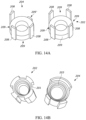
- FIGS. 16 A and 16 B show a further exemplary pair of zoom cells in accordance with embodiments of the present disclosure.
- FIGS. 17 A and 17 B are a view of the pair of zoom cells of FIG. 16 A positioned within an erector tube nearer the eyepiece end, in accordance with embodiments of the present disclosure.
- Spatial terms such as “beneath,” “below,” “lower,” “above,” “upper,” and the like, may be used herein for ease of description to describe one element's or feature's relationship to another element(s) or feature(s) as illustrated in the figures. It will be understood that the spatially relative terms are intended to encompass different orientations of device in use or operation in addition to the orientation depicted in the figures. For example, if the device in the figures is turned over, elements described as “below” or “beneath” other elements or features would then be oriented “above” the other elements or features. Thus, the exemplary term “below” can encompass both an orientation of above and below. The device may be otherwise oriented (rotated 90° or at other orientations) and the spatially relative descriptors used herein interpreted accordingly.
- the term “and/or” includes any and all combinations of one or more of the associated listed items.
- the phrase “and/or” is intended to include both A and B; A or B; A (alone); and B (alone).
- the term “and/or” as used in a phrase such as “A, B and/or C” is intended to encompass each of the following embodiments” A, B and C; A, B, or C; A or C; A or B; B or C; A and C; A and B; B and C; A (alone); B (alone); and C (alone).
- bearing surface is the area of contact between two objects.
- втори ⁇ е sleeve is a protrusion from the erector lens mount which engages a slot in the erector tube and/or cam tube which serves an analogous purpose. This could be integral to the mount or detachable.
- the terms “user” and “shooter” interchangeably refer to either the operator making the shot or an individual observing the shot in collaboration with the operator making the shot.
- the term “viewing optic” refers to an apparatus or assembly used by a user, a shooter or a spotter to select, identify and/or monitor a target.
- a viewing optic may rely on visual observation of the target or, for example, on infrared (IR), ultraviolet (UV), radar, thermal, microwave, magnetic imaging, radiation including X-ray, gamma ray, isotope and particle radiation, night vision, vibrational receptors including ultra-sound, sound pulse, sonar, seismic vibrations, magnetic resonance, gravitational receptors, broadcast frequencies including radio wave, television and cellular receptors, or other image of the target.
- IR infrared
- UV ultraviolet
- radar thermal, microwave
- magnetic imaging radiation including X-ray, gamma ray, isotope and particle radiation
- vibrational receptors including ultra-sound, sound pulse, sonar, seismic vibrations, magnetic resonance, gravitational receptors, broadcast frequencies including radio wave, television and cellular receptors, or other image of the target.
- the image of the target presented to a user/shooter/spotter by a viewing optic may be unaltered, or it may be enhanced, for example, by magnification, amplification, subtraction, superimposition, filtration, stabilization, template matching, or other means.
- the target selected, identified and/or monitored by a viewing optic may be within the line of sight of the shooter or tangential to the sight of the shooter. In other embodiments, the shooter's line of sight may be obstructed while the viewing optic presents a focused image of the target.
- the image of the target acquired by the viewing optic may, for example, be analog or digital, and shared, stored archived or transmitted within a network of one or more shooters and spotters by, for example, video, physical cable or wire, IR, radio wave, cellular connections, laser pulse, optical 802.11b or other wireless transmission using, for example, protocols such as html. SML, SOAP, X.25, SNA, etc., BluetoothTM, Serial, USB or other suitable image distribution method.
- the term “viewing optic” is used interchangeably with “optic sight.”
- a “firearm” is a portable gun, being a barreled weapon that launches one or more projectiles often driven by the action of an explosive force.
- the term “firearm” includes a handgun, a long gun, a rifle, shotgun, a carbine, automatic weapons, semi-automatic weapons, a machine gun, a sub-machine gun, an automatic rifle and an assault rifle.
- outward scene refers to a real world scene, including but not limited to a target.
- zeroing refers to aligning the point of aim (what the shooter is aiming at) and the point of impact (where the bullet fired from the firearm is actually hitting) at a specific distance. In one embodiment, zeroing is the process of adjusting a rifle scope or other viewing optic to a setting in which accurate allowance has been made for both windage and elevation for a specified range.
- FIGS. 1 and 2 illustrate an exemplary viewing optic 10 which is a rifle scope.
- the viewing optic 10 has a body or housing 12 that encloses a movable optical element 13 which is an erector tube.
- the scope body 12 is an elongate tube having a larger opening at its front 14 and a smaller opening at its rear 16 .
- An eyepiece 18 is attached to the rear of the scope body 12
- an objective lens 20 is attached to the front of the scope body 12 .
- the center axis of the movable optical element 13 defines the optical axis 17 of the optical device 10 .
- an elevation turret 22 and a windage turret 24 are two knobs in the outside center part of the scope body 12 . They are marked in increments by indicia 34 on their perimeters 30 and 32 and are used to adjust the elevation and windage of the movable optical element 13 for points of impact change. These knobs 22 , 24 protrude from the turret housing 36 .
- the turrets 22 , 24 are arranged so that the elevation turret rotation axis 26 is perpendicular to the windage turret rotation axis 28 .
- Indicia 34 typically include tick marks, each corresponding to a click, and larger tick marks at selected intervals, as well as numerals indicating angle of adjustment or distance for bullet drop compensation.
- the movable optical element 13 is adjusted by rotating the turrets one or more clicks.
- a click is one tactile adjustment increment on the windage or elevation turret of the viewing optic 10 , each of which corresponds to one of the indicia 34 .
- one click changes the viewing optic's point of impact by 0.1 milliradians (mrad).
- the turrets can be used with other units and measures of increments, including, for example, minutes of angle (MOA) increments.
- a power ring 11 is located at the eyepiece-end of the viewing optic 10 . Rotation of the power ring 11 adjusts the magnification by changing the position of one or more zoom cells 100 within the movable optical element 13 .
- the power ring 11 allows for continuous magnification adjustment within the range permitted by the viewing optic 10 . That is, in the embodiment shown, the power ring 11 does not have clicks or defined positions during rotation.
- the magnification does adjust by rotating the power ring 11 one or more clicks or tactile adjustment increment. For example, in an embodiment, one click changes the magnification by 1 ⁇ .
- the power ring 11 does not contain indicia. In further embodiments, the power ring 11 does contain indicia, each of which corresponds to a click or tactile adjustment increment.
- FIGS. 3 A and 3 B are schematics showing representative zoom cells of common (existing) design.
- the erector tube 13 is shown as a rectangle in which a zoom cell 100 a , 100 b is positioned.
- the zoom cells 100 a , 100 b are generally cylindrical and the schematics 3 A and 3 B have been simplified for illustrative purposes.
- the zoom cell 100 a represents a common zoom cell in its nominal position in which the optical axis 17 is the same as the center axis 17 of the zoom cell 100 a .
- the zoom cells 100 a , 100 b can tilt within the erector tube as shown with reference to zoom cells 100 b , causing angular deviation from the optical axis 17 .
- the bearing surface 110 or outer surface of the zoom cells 100 a , 100 b which is intended to slide within the erector tube 13 , is short. That is, the zoom cells 100 a , 100 b have a small length resulting in a low aspect ratio (width/diameter).
- the angular deviation ⁇ 1 of the zoom cell 100 b shown in FIG. 3 A is therefore greater than the angular deviation ⁇ 2 of the zoom cell 100 b shown in FIG. 3 B which includes a number of “fingers” 108 which increase the aspect ratio of the zoom cell 100 b .
- the angular deviation is decreased by over half.
- FIGS. 4 A and 4 B illustrate further representative zoom cells of common (existing) design.
- the angular deviation of the zoom cells 100 is controlled by physically limiting the space in which the zoom cells 100 can tilt.
- rotation of the zoom cells 100 about the optical axis is prevented or reduced using a pin/slot mechanism 105 , and angular deviation is mitigated by the minimal clearance between the bearing surfaces 110 of the zoom cells 100 and the inner surface of the erector tube 13 .
- the manufacturing of components with such minimal clearances and tolerances is in many instances difficult, costly and/or impractical.
- to be within the tolerances prescribed by a given optical design is not manufacturable due to high fallout rates and/or unachievable tolerances.
- FIG. 5 is a side perspective view of a pair of zoom cells 202 , 204 of a zoom cell system 200 in accordance with embodiments of the present disclosure.
- the zoom cells 202 , 204 each have an interrupted bearing surface 210 which creates, in essence, a number of fingers 208 separated by the same number of grooves 209 .
- the fingers 208 extend away from the main zoom cell bodies 201 , 203 , each in the same direction, parallel with the optical axis 17 .
- the zoom cells 202 , 204 are positioned within the erector tube 13 such that the fingers 208 of each of the zoom cells 202 , 204 extend towards one another. Further, the zoom cells 202 , 204 are rotationally offset from one another such that the fingers 208 of one of the zoom cells 202 , 204 align with the grooves 209 of the other of the zoom cells 202 , 204 , and vice versa. As such, the zoom cells 202 , 204 both have a large aspect ratio of 0.2 to 1.7 and are able to translate along the required functional range of the erector tube 13 by nesting with one another as shown in FIGS. 6 - 11 .
- the aspect ratio is at least 0.2. In another embodiment, the aspect ratio is at least 0.3. In one embodiment, the aspect ratio is less than 1.7. In another embodiment, the aspect ratio is less than 1.5. In still another embodiment, the aspect ratio is less than 1.2.
- the aspect ratio is from 0.2 to 1.4 or from 0.2 to 1.3 or from 0.2 to 1.2.
- the aspect ratio is from 0.3 to 1.4 or from 0.4 to 1.4 or from 0.5 to 1.4.
- the aspect ratio is from 0.3 to 1.2. In one embodiment, the aspect ratio is from 0.3 to 1.1, or from 0.3 to 1.0, or from 0.3 to 0.9, or from 0.3 to 0.8, or from 0.3 to 0.7, or or from 0.3 to 0.6, or from 0.3 to 0.5, or from 0.3 to 0.4.
- the aspect ratio is from 0.4 to 1.2 or from 0.5 to 1.2 or from 0.6 to 1.2, or from 0.7 to 1.2, or from 0.8 to 1.2, or from 0.9 to 1.2, or from 1.0 to 1.2, or from 1.1 to 1.2.
- zoom cells 202 , 204 have the same external diameter as measured with reference from the outer surface of the fingers 208 (i.e., the bearing surface 210 ).
- the outer diameter of each of zoom cells 202 , 204 is specifically calculated to be slightly less than the inner diameter of the erector tube 13 to further limit angular deviation but also not hinder movement of the zoom cells 202 , 204 within the erector tube 13 .
- FIGS. 5 - 11 Also shown in FIGS. 5 - 11 are the pin/slot mechanisms 205 that prevent the zoom cells 202 , 204 from rotating about the optical axis 17 within the erector tube 13 .
- Each zoom cell 202 , 204 has a pin 211 protruding from its bearing surface 210 .
- the pins 211 protrude from the surface of one of the fingers 208 .
- the erector tube 13 contains two slots 30 , each corresponding to one of the pins 211 of the zoom cells 202 , 204 .
- the erector tube housing 220 likewise includes two slots 222 , though the slots 222 of the erector tube housing 220 spiral around the optical axis 17 along the length of the erector tube housing 220 .
- the zoom cells 202 , 204 move not only in coordination in a translating fashion within the erector tube 13 , but also in coordination rotationally by virtue of the pins 211 engaging the spiral slots 222 .
- the grooves (or channels) 209 a respective one of the zoom cells 202 , 204 , has an arc length greater than that of the fingers 208 of the corresponding one of the zoom cells 202 , 204 .
- the fingers 208 of each zoom cell 202 , 204 can nest freely inside the grooves 209 of the other zoom cell 202 , 204 , and the rotational constraints of the zoom cells 202 , 204 , provided by the pin/slot mechanisms 205 discussed above, prevent the fingers 208 and grooves 209 of the corresponding finger 208 /groove 209 pairs from contacting one another.
- FIGS. 12 A, 12 B and 13 show the zoom cells 202 , 204 , respectively, in more detail.
- the zoom cells 202 , 204 each have three fingers 208 and three grooves 209 , and the fingers 208 and grooves 209 are evenly disposed about the main zoom cell bodies 201 , 203 .
- the fingers 208 extend outward from the main zoom cell bodies 201 , 203 , respectively, and each in the same direction perpendicular to the circumference.
- the zoom cells 202 , 204 may have differing numbers of fingers and grooves, including, for example, from 2, or 3, or 4, or 5, or 6 to 7, or 8, or 9, or 10 fingers and from 2, or 3, or 4, or 5, or 6 to 7, or 8, or 9, or 10 grooves.
- a zoom cell 202 , 204 may have an even number of fingers and grooves, or an odd number of fingers and grooves.
- one of the zoom cells 202 includes four fingers 208 and four grooves 209
- the other of the zoom cells 204 includes three fingers 208 and three grooves 209 .
- FIGS. 14 A- 14 E one of the zoom cells 202 includes four fingers 208 and four grooves 209
- the other of the zoom cells 204 includes three fingers 208 and three grooves 209 .
- one of the zoom cells 202 includes six fingers 208 and six grooves 209
- the other of the zoom cells 204 includes five fingers 208 and five grooves 209 .
- a single groove 209 may then correspond to two or more fingers 208 on its corresponding zoom cell, as shown, for example, in FIGS. 14 D- 14 E and 15 D- 15 E .
- each zoom cell 202 , 204 includes more than one finger and more than one groove.
- zoom cell 204 has three fingers 208 that are not evenly distributed around the main zoom cell body 203 but otherwise evenly spaced within approximately 3 ⁇ 4 of the circumference of the main zoom cell body 203 .
- one of the grooves 209 ′ has a greater arc length than the other grooves 209 .
- zoom cell 204 of FIG. 15 A has fingers 208 that are not evenly distributed around the main zoom cell body 203 but are otherwise evenly spaced within approximately 3 ⁇ 4 of the circumference of the main zoom cell body 203 .
- groove 209 ′ has a greater arc length than the other grooves 209 .
- each zoom cell 202 , 204 has a cumulative bearing surface 210 (i.e., the outer surface of the fingers 208 ) which is greater than 180° about the primary axis (i.e., optical axis 17 ) but less than 360°.
- the zoom cells 202 , 204 have a cumulative bearing surface 210 less than 180° per zoom cell. Both zoom cells meshed together plus the clearance space between the fingers and grooves will equal the 360 degrees.
- the cumulative bearing surface needs to be distributed around the central axis such that they axis of the erector tube and zoom cell remine colinear.
- the zoom cells 202 , 204 have a cumulative bearing surface 210 from greater than 180°, or 185°, or 190°, or 195°, or 200° to 205°, or 210°, or 215°, or 220°, or 225°, or 230°, or 240°, or 250°, or 300°, or less than 360°.
- zoom cells 202 , 204 are manufactured starting with a solid, cylindrical tube of a desired length (or width, as the dimension is referred to in the final product).
- the cylindrical tube may have a hollow central bore or a hollow central bore may be machined into the cylinder.
- the grooves (and fingers) are created through a milling process (removing material).
- the fingers may be added to a base structure or the entire structure may be manufactured using an additive process such as 3D-printing.
- the zoom cells 202 , 204 are made of metal; however, other materials having sufficient strength, durability and integrity for the intended purpose are also contemplated.
- each zoom cell can have two fingers and two grooves.
- FIGS. 16 A and 16 B show the zoom cells 302 , 304 , respectively, in more detail.
- the zoom cells 302 , 304 each have two fingers, 305 , and two grooves 309 , and the fingers 305 and grooves 309 can be evenly disposed about the main zoom cell bodies.
- the fingers 305 extend outward from the main zoom cell bodies, respectively, and each in the same direction perpendicular to the circumference.
- FIGS. 16 A and 16 B are the pin mechanisms, 307 , which prevent the zoom cells 302 , 304 from rotating about the optical axis within the erector tube.
- Each zoom cell 302 , 304 has two pins 307 , protruding from its bearing surface.
- the pins 307 protrude from the surface of each finger 305 of each zoom cell, 302 , 304 .
- the erector tube contains four slots, each corresponding to one of the pins 307 of the zoom cells 302 , 304 .
- the erector tube housing likewise includes four slots, though the slots of the erector tube housing spiral around the optical axis along the length of the erector tube housing.
- FIGS. 17 A and 17 B are views of a pair of zoom cells 302 , 304 of a zoom cell system in accordance with embodiments of the present disclosure.
- the zoom cells 302 , 304 each have an interrupted bearing surface that creates two fingers separated by two grooves as shown in FIGS. 16 A and 16 B .
- the fingers extend away from the main zoom cell bodies, each in the same direction, parallel with the optical axis.
- the zoom cells 302 , 304 are positioned within the erector tube such that the fingers of each of the zoom cells 302 , 304 extend towards one another. Further, the zoom cells 302 , 304 are rotationally offset from one another such that the fingers of one of the zoom cells 302 , 304 align with the grooves of the other of the zoom cells 302 , 304 , and vice versa.
- Each zoom cell, 302 , 304 has two pins 307 , with a pin 307 projecting outwardly away from each finger in a direction perpendicular to the central axis.
- a zoom cell has at least two pins. In one embodiment, a zoom cell has 1, 2, 3, 4, 5, or greater than 5 pins. In one embodiment, each zoom cell of a zoom cell system may have an equal number of pins. In another embodiment, one zoom cell of a zoom cell system may have a greater number of pins as compared to another zoom cell of the zoom cell system. In another embodiment, one zoom cell of a zoom cell system may have a lesser number of pins as compared to another zoom cell of the zoom cell system.
- each finger of each zoom cell has at least one pin. In another embodiment, each finger of each zoom cell has at least two pins. In one embodiment, each finger of a zoom cell may have an equal number of pins. In another embodiment, one finger of a zoom cell may have a different number of pins as compared to a different finger of the same zoom cell. In one embodiment, a finger of a zoom cell may have a greater number of pins as compared to a different finger of the same zoom cell. In another embodiment, a finger of a zoom cell may have a lesser number of pins as compared to a different finger of the same zoom cell.
- the zoom cells of a zoom cell system may have an equal number of pins. In another embodiment, the zoom cells of a zoom cell system may have a different number of pins. In one embodiment, one zoom cell of a zoom cell system may have a greater number of pins as compared to a different zoom cell of the same zoom cell system. In one embodiment, one zoom cell of a zoom cell system may have a lesser number of pins as compared to a different zoom cell of the same zoom cell system.
- pin axes are 90° offset. In one embodiment, pin axes are 45° offset. In another embodiment, pin axes are 180° offset. In another embodiment, pin axes are 270° offset.
- the erector tube has an equivalent number of slots to the total number of pins of the zoom cells. In one embodiment, the erector tube housing has an equivalent number of slots to the total number of pins of the zoom cells.
- the erector tube has an equivalent number of slots to the total number of pins of the zoom cell system. In one embodiment, the erector tube housing has an equivalent number of slots to the total number of pins of the zoom cell system.
Landscapes
- Physics & Mathematics (AREA)
- Optics & Photonics (AREA)
- General Physics & Mathematics (AREA)
- Astronomy & Astrophysics (AREA)
- Engineering & Computer Science (AREA)
- General Engineering & Computer Science (AREA)
- Microscoopes, Condenser (AREA)
- Apparatus Associated With Microorganisms And Enzymes (AREA)
- Lubrication Of Internal Combustion Engines (AREA)
Priority Applications (2)
| Application Number | Priority Date | Filing Date | Title |
|---|---|---|---|
| US17/149,086 US11629933B2 (en) | 2020-01-15 | 2021-01-14 | Zoom cell |
| US18/301,682 US20230384057A1 (en) | 2020-01-15 | 2023-04-17 | Zoom cell |
Applications Claiming Priority (2)
| Application Number | Priority Date | Filing Date | Title |
|---|---|---|---|
| US202062961464P | 2020-01-15 | 2020-01-15 | |
| US17/149,086 US11629933B2 (en) | 2020-01-15 | 2021-01-14 | Zoom cell |
Related Child Applications (1)
| Application Number | Title | Priority Date | Filing Date |
|---|---|---|---|
| US18/301,682 Continuation US20230384057A1 (en) | 2020-01-15 | 2023-04-17 | Zoom cell |
Publications (2)
| Publication Number | Publication Date |
|---|---|
| US20210381803A1 US20210381803A1 (en) | 2021-12-09 |
| US11629933B2 true US11629933B2 (en) | 2023-04-18 |
Family
ID=76864686
Family Applications (2)
| Application Number | Title | Priority Date | Filing Date |
|---|---|---|---|
| US17/149,086 Active 2041-01-14 US11629933B2 (en) | 2020-01-15 | 2021-01-14 | Zoom cell |
| US18/301,682 Pending US20230384057A1 (en) | 2020-01-15 | 2023-04-17 | Zoom cell |
Family Applications After (1)
| Application Number | Title | Priority Date | Filing Date |
|---|---|---|---|
| US18/301,682 Pending US20230384057A1 (en) | 2020-01-15 | 2023-04-17 | Zoom cell |
Country Status (8)
| Country | Link |
|---|---|
| US (2) | US11629933B2 (fr) |
| EP (1) | EP4090905B1 (fr) |
| KR (1) | KR20220159954A (fr) |
| CN (2) | CN118310372A (fr) |
| AU (1) | AU2021207485A1 (fr) |
| CA (1) | CA3168228A1 (fr) |
| WO (1) | WO2021146403A1 (fr) |
| ZA (1) | ZA202208936B (fr) |
Cited By (1)
| Publication number | Priority date | Publication date | Assignee | Title |
|---|---|---|---|---|
| US20230384057A1 (en) * | 2020-01-15 | 2023-11-30 | Sheltered Wings, Inc. D/B/A Vortex Optics | Zoom cell |
Families Citing this family (2)
| Publication number | Priority date | Publication date | Assignee | Title |
|---|---|---|---|---|
| KR102895108B1 (ko) * | 2019-06-05 | 2025-12-03 | 쉘터드 윙스, 인크. 디/비/에이 보텍스 옵틱스 | 디옵터 조정 메커니즘 |
| JP7566832B2 (ja) * | 2022-09-13 | 2024-10-15 | キヤノン株式会社 | レンズ鏡筒 |
Citations (22)
| Publication number | Priority date | Publication date | Assignee | Title |
|---|---|---|---|---|
| US3058391A (en) * | 1960-12-19 | 1962-10-16 | Leupold & Stevens Instr Inc | Variable power rifle scope |
| US3121134A (en) * | 1960-12-05 | 1964-02-11 | William R Weaver | Variable power telescope sight |
| US3445155A (en) * | 1965-08-13 | 1969-05-20 | Bell & Howell Co | Mechanism for relative adjustment of axially spaced lens element |
| US3618498A (en) * | 1970-07-23 | 1971-11-09 | Bell & Howell Co | Chromatic rangefinder |
| US3744884A (en) * | 1971-11-02 | 1973-07-10 | Bell & Howell Co | Lens mount assembly for focusable, variable focal length lens |
| US4172634A (en) * | 1977-09-28 | 1979-10-30 | W. R. Weaver Company | Cam follower for variable power scopes |
| US5583595A (en) * | 1992-01-07 | 1996-12-10 | Olympus Optical Co., Ltd. | Lens barrel |
| US5793537A (en) * | 1996-01-26 | 1998-08-11 | Asahi Kogaku Kogyo Kabushiki Kaisha | Lens barrel having a linear guide mechanism |
| US6031663A (en) * | 1995-08-24 | 2000-02-29 | Asahi Kogaku Kogyo Kabushiki Kaisha | Binocular |
| US6195212B1 (en) * | 1998-11-11 | 2001-02-27 | Nikon Corporation | Variable focal length lens barrel |
| US6449108B1 (en) * | 2001-01-05 | 2002-09-10 | Burris Company, Inc. | Synthetic erector lens mount |
| US20100284081A1 (en) * | 2009-05-08 | 2010-11-11 | Gutierrez Roman C | Integrated lens barrel |
| US20100309462A1 (en) * | 2005-01-26 | 2010-12-09 | Leupold & Stevens, Inc. | Scope with improved magnification system |
| US8314994B1 (en) * | 2009-07-29 | 2012-11-20 | Yt Products, Llc | Scope having a zoom slider |
| US20130318853A1 (en) * | 2010-01-19 | 2013-12-05 | Schmidt & Bender Gmbh & Co. Kg | Sighting telescope |
| US8699149B2 (en) * | 2011-01-28 | 2014-04-15 | Schimdt & Bender GmbH & Co. KG | Reversing system for a sighting telescope |
| US20150022884A1 (en) * | 2013-07-20 | 2015-01-22 | Peter Hakel | Sextant telescope with a zoom feature |
| US20150124243A1 (en) * | 2013-11-06 | 2015-05-07 | Lightforce USA, Inc., d/b/a/ Nightforce Optics, Inc. | Telescopic sights for firearms, and related methods |
| US20150323780A1 (en) | 2013-09-06 | 2015-11-12 | Sheltered Wings, Inc. | Dual focal plane reticles for optical sighting devices |
| US20160356981A1 (en) * | 2015-06-03 | 2016-12-08 | Flir Systems, Inc. | Lens cell preloading systems and methods |
| US20180217367A1 (en) * | 2017-01-26 | 2018-08-02 | Navitar, Inc. | High Etendue Modular Lens Assembly with Afocal Zoom |
| US20180341082A1 (en) * | 2017-05-25 | 2018-11-29 | Lightforce USA, Inc., d/b/a/ Nightforce Optics, Inc. | Erector cam |
Family Cites Families (7)
| Publication number | Priority date | Publication date | Assignee | Title |
|---|---|---|---|---|
| US4403421A (en) * | 1980-11-13 | 1983-09-13 | Shepherd Daniel R | Telescopic gun sight |
| CA1336656C (fr) * | 1988-06-03 | 1995-08-15 | Hiroshi Nomura | Camera a teleobjectif dote d'un element optique correcteur |
| US7227682B2 (en) * | 2005-04-08 | 2007-06-05 | Panavision International, L.P. | Wide-range, wide-angle compound zoom with simplified zooming structure |
| JP2007248770A (ja) * | 2006-03-15 | 2007-09-27 | Fujinon Corp | ズームレンズ装置 |
| JP4857063B2 (ja) * | 2006-09-29 | 2012-01-18 | キヤノン株式会社 | ズームレンズ及びそれを有する撮像装置 |
| JP2014534462A (ja) * | 2011-10-07 | 2014-12-18 | シンガポール国立大学National University Of Singapore | Mems型ズームレンズシステム |
| CN118310372A (zh) * | 2020-01-15 | 2024-07-09 | 夏尔特银斯公司 | 变焦单元 |
-
2021
- 2021-01-14 CN CN202410599908.2A patent/CN118310372A/zh active Pending
- 2021-01-14 KR KR1020227028263A patent/KR20220159954A/ko active Pending
- 2021-01-14 US US17/149,086 patent/US11629933B2/en active Active
- 2021-01-14 WO PCT/US2021/013409 patent/WO2021146403A1/fr not_active Ceased
- 2021-01-14 EP EP21740784.0A patent/EP4090905B1/fr active Active
- 2021-01-14 CA CA3168228A patent/CA3168228A1/fr active Pending
- 2021-01-14 CN CN202180016083.1A patent/CN115151781B/zh active Active
- 2021-01-14 AU AU2021207485A patent/AU2021207485A1/en active Pending
-
2022
- 2022-08-10 ZA ZA2022/08936A patent/ZA202208936B/en unknown
-
2023
- 2023-04-17 US US18/301,682 patent/US20230384057A1/en active Pending
Patent Citations (22)
| Publication number | Priority date | Publication date | Assignee | Title |
|---|---|---|---|---|
| US3121134A (en) * | 1960-12-05 | 1964-02-11 | William R Weaver | Variable power telescope sight |
| US3058391A (en) * | 1960-12-19 | 1962-10-16 | Leupold & Stevens Instr Inc | Variable power rifle scope |
| US3445155A (en) * | 1965-08-13 | 1969-05-20 | Bell & Howell Co | Mechanism for relative adjustment of axially spaced lens element |
| US3618498A (en) * | 1970-07-23 | 1971-11-09 | Bell & Howell Co | Chromatic rangefinder |
| US3744884A (en) * | 1971-11-02 | 1973-07-10 | Bell & Howell Co | Lens mount assembly for focusable, variable focal length lens |
| US4172634A (en) * | 1977-09-28 | 1979-10-30 | W. R. Weaver Company | Cam follower for variable power scopes |
| US5583595A (en) * | 1992-01-07 | 1996-12-10 | Olympus Optical Co., Ltd. | Lens barrel |
| US6031663A (en) * | 1995-08-24 | 2000-02-29 | Asahi Kogaku Kogyo Kabushiki Kaisha | Binocular |
| US5793537A (en) * | 1996-01-26 | 1998-08-11 | Asahi Kogaku Kogyo Kabushiki Kaisha | Lens barrel having a linear guide mechanism |
| US6195212B1 (en) * | 1998-11-11 | 2001-02-27 | Nikon Corporation | Variable focal length lens barrel |
| US6449108B1 (en) * | 2001-01-05 | 2002-09-10 | Burris Company, Inc. | Synthetic erector lens mount |
| US20100309462A1 (en) * | 2005-01-26 | 2010-12-09 | Leupold & Stevens, Inc. | Scope with improved magnification system |
| US20100284081A1 (en) * | 2009-05-08 | 2010-11-11 | Gutierrez Roman C | Integrated lens barrel |
| US8314994B1 (en) * | 2009-07-29 | 2012-11-20 | Yt Products, Llc | Scope having a zoom slider |
| US20130318853A1 (en) * | 2010-01-19 | 2013-12-05 | Schmidt & Bender Gmbh & Co. Kg | Sighting telescope |
| US8699149B2 (en) * | 2011-01-28 | 2014-04-15 | Schimdt & Bender GmbH & Co. KG | Reversing system for a sighting telescope |
| US20150022884A1 (en) * | 2013-07-20 | 2015-01-22 | Peter Hakel | Sextant telescope with a zoom feature |
| US20150323780A1 (en) | 2013-09-06 | 2015-11-12 | Sheltered Wings, Inc. | Dual focal plane reticles for optical sighting devices |
| US20150124243A1 (en) * | 2013-11-06 | 2015-05-07 | Lightforce USA, Inc., d/b/a/ Nightforce Optics, Inc. | Telescopic sights for firearms, and related methods |
| US20160356981A1 (en) * | 2015-06-03 | 2016-12-08 | Flir Systems, Inc. | Lens cell preloading systems and methods |
| US20180217367A1 (en) * | 2017-01-26 | 2018-08-02 | Navitar, Inc. | High Etendue Modular Lens Assembly with Afocal Zoom |
| US20180341082A1 (en) * | 2017-05-25 | 2018-11-29 | Lightforce USA, Inc., d/b/a/ Nightforce Optics, Inc. | Erector cam |
Non-Patent Citations (2)
| Title |
|---|
| International Preliminary Report on Patentability issued for International Application No. PCT/US21/13409 dated Jul. 19, 2022, 7 pages. |
| International Search Report and Written Opinion for International Application No. PCT/US21/13409 dated May 19, 2021, 10 pages. |
Cited By (1)
| Publication number | Priority date | Publication date | Assignee | Title |
|---|---|---|---|---|
| US20230384057A1 (en) * | 2020-01-15 | 2023-11-30 | Sheltered Wings, Inc. D/B/A Vortex Optics | Zoom cell |
Also Published As
| Publication number | Publication date |
|---|---|
| CN115151781A (zh) | 2022-10-04 |
| ZA202208936B (en) | 2023-11-29 |
| EP4090905A1 (fr) | 2022-11-23 |
| CN118310372A (zh) | 2024-07-09 |
| CN115151781B (zh) | 2024-05-31 |
| US20230384057A1 (en) | 2023-11-30 |
| WO2021146403A1 (fr) | 2021-07-22 |
| EP4090905B1 (fr) | 2026-03-25 |
| US20210381803A1 (en) | 2021-12-09 |
| EP4090905A4 (fr) | 2024-05-29 |
| KR20220159954A (ko) | 2022-12-05 |
| CA3168228A1 (fr) | 2021-07-22 |
| AU2021207485A1 (en) | 2022-08-18 |
Similar Documents
| Publication | Publication Date | Title |
|---|---|---|
| US20230384057A1 (en) | Zoom cell | |
| US20240272418A1 (en) | Viewing optic with a base having a light module | |
| US12372739B2 (en) | Turret with a zero stop | |
| KR101344981B1 (ko) | 다중 탄도보정장치 | |
| EP3980833B1 (fr) | Mécanisme d'ajustement dioptrique | |
| EP2901197B1 (fr) | Dispositif de visée optique | |
| US20230350174A1 (en) | Viewing Optic with Magnification Adjustment Ring | |
| US20240369823A1 (en) | Diopter adjustment and locking mechanism using left and right threading on the same pitch diameter |
Legal Events
| Date | Code | Title | Description |
|---|---|---|---|
| FEPP | Fee payment procedure |
Free format text: ENTITY STATUS SET TO UNDISCOUNTED (ORIGINAL EVENT CODE: BIG.); ENTITY STATUS OF PATENT OWNER: SMALL ENTITY |
|
| FEPP | Fee payment procedure |
Free format text: ENTITY STATUS SET TO SMALL (ORIGINAL EVENT CODE: SMAL); ENTITY STATUS OF PATENT OWNER: SMALL ENTITY |
|
| AS | Assignment |
Owner name: SHELTERED WINGS, INC. D/B/A VORTEX OPTICS, WISCONSIN Free format text: ASSIGNMENT OF ASSIGNORS INTEREST;ASSIGNOR:MCDERMOT, CONNOR;REEL/FRAME:055090/0518 Effective date: 20210127 |
|
| STPP | Information on status: patent application and granting procedure in general |
Free format text: DOCKETED NEW CASE - READY FOR EXAMINATION |
|
| AS | Assignment |
Owner name: PNC BANK, NATIONAL ASSOCIATION, PENNSYLVANIA Free format text: SECURITY INTEREST;ASSIGNOR:SHELTERED WINGS, INC., D/B/A VORTEX OPTICS, A WISCONSIN CORPORATION;REEL/FRAME:059364/0670 Effective date: 20220311 |
|
| STPP | Information on status: patent application and granting procedure in general |
Free format text: NON FINAL ACTION MAILED |
|
| STPP | Information on status: patent application and granting procedure in general |
Free format text: RESPONSE TO NON-FINAL OFFICE ACTION ENTERED AND FORWARDED TO EXAMINER |
|
| STPP | Information on status: patent application and granting procedure in general |
Free format text: NOTICE OF ALLOWANCE MAILED -- APPLICATION RECEIVED IN OFFICE OF PUBLICATIONS |
|
| STCF | Information on status: patent grant |
Free format text: PATENTED CASE |