US11743458B2 - Method and apparatus for reduction of in-loop filter buffer - Google Patents
Method and apparatus for reduction of in-loop filter buffer Download PDFInfo
- Publication number
- US11743458B2 US11743458B2 US17/286,713 US201917286713A US11743458B2 US 11743458 B2 US11743458 B2 US 11743458B2 US 201917286713 A US201917286713 A US 201917286713A US 11743458 B2 US11743458 B2 US 11743458B2
- Authority
- US
- United States
- Prior art keywords
- block
- pixels
- line
- target
- pixel
- Prior art date
- Legal status (The legal status is an assumption and is not a legal conclusion. Google has not performed a legal analysis and makes no representation as to the accuracy of the status listed.)
- Active, expires
Links
Images


Classifications
-
- H—ELECTRICITY
- H04—ELECTRIC COMMUNICATION TECHNIQUE
- H04N—PICTORIAL COMMUNICATION, e.g. TELEVISION
- H04N19/00—Methods or arrangements for coding, decoding, compressing or decompressing digital video signals
- H04N19/80—Details of filtering operations specially adapted for video compression, e.g. for pixel interpolation
- H04N19/82—Details of filtering operations specially adapted for video compression, e.g. for pixel interpolation involving filtering within a prediction loop
-
- H—ELECTRICITY
- H04—ELECTRIC COMMUNICATION TECHNIQUE
- H04N—PICTORIAL COMMUNICATION, e.g. TELEVISION
- H04N19/00—Methods or arrangements for coding, decoding, compressing or decompressing digital video signals
- H04N19/10—Methods or arrangements for coding, decoding, compressing or decompressing digital video signals using adaptive coding
- H04N19/102—Methods or arrangements for coding, decoding, compressing or decompressing digital video signals using adaptive coding characterised by the element, parameter or selection affected or controlled by the adaptive coding
- H04N19/117—Filters, e.g. for pre-processing or post-processing
-
- H—ELECTRICITY
- H04—ELECTRIC COMMUNICATION TECHNIQUE
- H04N—PICTORIAL COMMUNICATION, e.g. TELEVISION
- H04N19/00—Methods or arrangements for coding, decoding, compressing or decompressing digital video signals
- H04N19/10—Methods or arrangements for coding, decoding, compressing or decompressing digital video signals using adaptive coding
- H04N19/102—Methods or arrangements for coding, decoding, compressing or decompressing digital video signals using adaptive coding characterised by the element, parameter or selection affected or controlled by the adaptive coding
- H04N19/132—Sampling, masking or truncation of coding units, e.g. adaptive resampling, frame skipping, frame interpolation or high-frequency transform coefficient masking
-
- H—ELECTRICITY
- H04—ELECTRIC COMMUNICATION TECHNIQUE
- H04N—PICTORIAL COMMUNICATION, e.g. TELEVISION
- H04N19/00—Methods or arrangements for coding, decoding, compressing or decompressing digital video signals
- H04N19/10—Methods or arrangements for coding, decoding, compressing or decompressing digital video signals using adaptive coding
- H04N19/134—Methods or arrangements for coding, decoding, compressing or decompressing digital video signals using adaptive coding characterised by the element, parameter or criterion affecting or controlling the adaptive coding
- H04N19/167—Position within a video image, e.g. region of interest [ROI]
-
- H—ELECTRICITY
- H04—ELECTRIC COMMUNICATION TECHNIQUE
- H04N—PICTORIAL COMMUNICATION, e.g. TELEVISION
- H04N19/00—Methods or arrangements for coding, decoding, compressing or decompressing digital video signals
- H04N19/10—Methods or arrangements for coding, decoding, compressing or decompressing digital video signals using adaptive coding
- H04N19/169—Methods or arrangements for coding, decoding, compressing or decompressing digital video signals using adaptive coding characterised by the coding unit, i.e. the structural portion or semantic portion of the video signal being the object or the subject of the adaptive coding
- H04N19/17—Methods or arrangements for coding, decoding, compressing or decompressing digital video signals using adaptive coding characterised by the coding unit, i.e. the structural portion or semantic portion of the video signal being the object or the subject of the adaptive coding the unit being an image region, e.g. an object
- H04N19/176—Methods or arrangements for coding, decoding, compressing or decompressing digital video signals using adaptive coding characterised by the coding unit, i.e. the structural portion or semantic portion of the video signal being the object or the subject of the adaptive coding the unit being an image region, e.g. an object the region being a block, e.g. a macroblock
-
- H—ELECTRICITY
- H04—ELECTRIC COMMUNICATION TECHNIQUE
- H04N—PICTORIAL COMMUNICATION, e.g. TELEVISION
- H04N19/00—Methods or arrangements for coding, decoding, compressing or decompressing digital video signals
- H04N19/10—Methods or arrangements for coding, decoding, compressing or decompressing digital video signals using adaptive coding
- H04N19/169—Methods or arrangements for coding, decoding, compressing or decompressing digital video signals using adaptive coding characterised by the coding unit, i.e. the structural portion or semantic portion of the video signal being the object or the subject of the adaptive coding
- H04N19/182—Methods or arrangements for coding, decoding, compressing or decompressing digital video signals using adaptive coding characterised by the coding unit, i.e. the structural portion or semantic portion of the video signal being the object or the subject of the adaptive coding the unit being a pixel
-
- H—ELECTRICITY
- H04—ELECTRIC COMMUNICATION TECHNIQUE
- H04N—PICTORIAL COMMUNICATION, e.g. TELEVISION
- H04N19/00—Methods or arrangements for coding, decoding, compressing or decompressing digital video signals
- H04N19/10—Methods or arrangements for coding, decoding, compressing or decompressing digital video signals using adaptive coding
- H04N19/169—Methods or arrangements for coding, decoding, compressing or decompressing digital video signals using adaptive coding characterised by the coding unit, i.e. the structural portion or semantic portion of the video signal being the object or the subject of the adaptive coding
- H04N19/186—Methods or arrangements for coding, decoding, compressing or decompressing digital video signals using adaptive coding characterised by the coding unit, i.e. the structural portion or semantic portion of the video signal being the object or the subject of the adaptive coding the unit being a colour or a chrominance component
-
- H—ELECTRICITY
- H04—ELECTRIC COMMUNICATION TECHNIQUE
- H04N—PICTORIAL COMMUNICATION, e.g. TELEVISION
- H04N19/00—Methods or arrangements for coding, decoding, compressing or decompressing digital video signals
- H04N19/42—Methods or arrangements for coding, decoding, compressing or decompressing digital video signals characterised by implementation details or hardware specially adapted for video compression or decompression, e.g. dedicated software implementation
- H04N19/423—Methods or arrangements for coding, decoding, compressing or decompressing digital video signals characterised by implementation details or hardware specially adapted for video compression or decompression, e.g. dedicated software implementation characterised by memory arrangements
- H04N19/426—Methods or arrangements for coding, decoding, compressing or decompressing digital video signals characterised by implementation details or hardware specially adapted for video compression or decompression, e.g. dedicated software implementation characterised by memory arrangements using memory downsizing methods
-
- H—ELECTRICITY
- H04—ELECTRIC COMMUNICATION TECHNIQUE
- H04N—PICTORIAL COMMUNICATION, e.g. TELEVISION
- H04N19/00—Methods or arrangements for coding, decoding, compressing or decompressing digital video signals
- H04N19/80—Details of filtering operations specially adapted for video compression, e.g. for pixel interpolation
Definitions
- the present invention relates to filter processing in a video coding system.
- the present invention relates to method and apparatus related to in-loop filter processing across a tile or slice boundary in a video encoder or decoder.
- Motion estimation is an effective inter-frame coding technique to exploit temporal redundancy in video sequences.
- Motion-compensated inter-frame coding has been widely used in various international video coding standards
- the motion estimation adopted in various coding standards is often a block-based technique, where motion information such as coding mode and motion vector is determined for each macroblock or similar block configuration.
- intra-coding is also adaptively applied, where the picture is processed without reference to any other picture.
- the inter-predicted or intra-predicted residues are usually further processed by transformation, quantization, and entropy coding to generate a compressed video bitstream.
- coding artefacts are introduced, particularly in the quantization process.
- additional processing has been applied to reconstructed video to enhance picture quality in newer coding systems.
- the additional processing is often configured in an in-loop operation so that the encoder and decoder may derive the same reference pictures to achieve improved system performance.
- FIG. 1 A illustrates an exemplary adaptive Inter/Intra video coding system incorporating in-loop processing.
- Motion Estimation (ME)/Motion Compensation (MC) 112 is used to provide prediction data based on video data from other picture or pictures.
- Switch 114 selects Intra Prediction 110 or inter-prediction data and the selected prediction data is supplied to Adder 116 to form prediction errors, also called residues.
- the prediction error is then processed by Transformation (T) 118 followed by Quantization (Q) 120 .
- T Transformation
- Q Quantization
- the transformed and quantized residues are then coded by Entropy Encoder 122 to form a video bitstream corresponding to the compressed video data.
- the bitstream associated with the transform coefficients is then packed with side information such as motion, mode, and other information associated with the image area.
- the side information may also be subject to entropy coding to reduce required bandwidth. Accordingly, the data associated with the side information are provided to Entropy Encoder 122 as shown in FIG. 1 A .
- Entropy Encoder 122 When an inter-prediction mode is used, a reference picture or pictures have to be reconstructed at the encoder end as well. Consequently, the transformed and quantized residues are processed by Inverse Quantization (IQ) 124 and Inverse Transformation (IT) 126 to recover the residues. The residues are then added back to prediction data 136 at Reconstruction (REC) 128 to reconstruct video data.
- the reconstructed video data may be stored in Reference Picture Buffer 134 and used for prediction of other frames.
- incoming video data undergoes a series of processing in the encoding system.
- the reconstructed video data from REC 128 may be subject to various impairments due to a series of processing. Accordingly, various in-loop processing is applied to the reconstructed video data before the reconstructed video data are stored in the Reference Picture Buffer 134 in order to improve video quality.
- HEVC High Efficiency Video Coding
- Deblocking Filter (DF) 130 Deblocking Filter
- SAO Sample Adaptive Offset
- ALF Adaptive Loop Filter
- the in-loop filter information may have to be incorporated in the bitstream so that a decoder can properly recover the required information.
- in-loop filter information from SAO and ALF is provided to Entropy Encoder 122 for incorporation into the bitstream.
- DF 130 is applied to the reconstructed video first; SAO 131 is then applied to DF-processed video; and ALF 132 is applied to SAO-processed video.
- ALF 132 is applied to SAO-processed video.
- the processing order among DF, SAO and ALF can be re-arranged.
- FIG. 1 B A corresponding decoder for the encoder of FIG. 1 A is shown in FIG. 1 B .
- the video bitstream is decoded by Video Decoder 142 to recover the transformed and quantized residues, SAO/ALF information and other system information.
- Video Decoder 142 At the decoder side, only Motion Compensation (MC) 113 is performed instead of ME/MC.
- MC Motion Compensation
- the decoding process is similar to the reconstruction loop at the encoder side.
- the recovered transformed and quantized residues, SAO/ALF information and other system information are used to reconstruct the video data.
- the reconstructed video is further processed by DF 130 , SAO 131 and ALF 132 to produce the final enhanced decoded video.
- the coding process in HEVC is applied according to Largest Coding Unit (LCU).
- LCU Largest Coding Unit
- the LCU is adaptively partitioned into coding units using quadtree.
- DF is performed for each 8 ⁇ 8 block and in HEVC Test Model Version 4.0 (HM-4.0), the DF is applies to 8 ⁇ 8 block boundaries.
- HM-4.0 HEVC Test Model Version 4.0
- four pixels of each side are involved in filter parameter derivation, and up to three pixels on each side can be changed after filtering.
- unfiltered reconstructed pixels i.e., pre-DF pixels
- filter parameter derivation For horizontal filtering across vertical block boundaries, unfiltered reconstructed pixels (i.e., pre-DF pixels) are used for filter parameter derivation and also used as source pixels for filtering.
- unfiltered reconstructed pixels i.e., pre-DF pixels
- DF intermediate pixels i.e. pixels after horizontal filtering
- For DF processing of a chroma block boundary two pixels of each side are involved in filter parameter derivation, and at most one pixel on each side is changed after filtering.
- unfiltered reconstructed pixels are used for filter parameter derivation and are used as source pixels for filtering.
- DF processed intermediate pixels i.e. pixels after horizontal filtering
- Sample Adaptive Offset (SAO) 131 is also adopted in HM-4.0, as shown in FIG. 1 A .
- SAO can be regarded as a special case of filtering where the processing only applies to one pixel.
- pixel classification is first done to classify pixels into different groups (also called categories or classes). The pixel classification for each pixel is based on a 3 ⁇ 3 window. Upon the classification of all pixels in a picture or a region, one offset is derived and transmitted for each group of pixels.
- ALF is not adopted by the HEVC (High Efficiency Video Coding). However, ALF is being considered for the emerging video coding standard, named VVC (Versatile Video Coding).
- the filter coefficients of ALF are derived by minimizing the sum of the distortion between filtered samples and original samples. Furthermore, the derived filter coefficients are signalled in the bitstream with on/off control flags. Multiple filters can be used in one slice and the filter selection includes implicit selection by block-based classification and explicit selection by signalled syntax.
- FIG. 2 shows a vertical boundary 212 in block 210 and a horizontal boundary 222 in block 220 , where 8 ⁇ 8 blocks are partly shown (4 ⁇ 8 or 8 ⁇ 4).
- all vertical boundaries can be horizontally filtered in parallel, and then all horizontal boundaries can be vertically filtered in parallel.
- four pixels of each side p 0 -p 3 , q 0 -q 3 ) are involved in filter parameter derivation, and at most three pixels of each side (p 0 -p 2 , q 0 -q 2 ) can be changed after filtering.
- pre-DF pixels i.e. pixels before horizontal DF
- pre-DF pixels are used for deriving filter parameters
- H-DF pixels are used for filtering.
- two pixels of each side p 0 -p 1 , q 0 -q 1 ) are involved in filter parameter derivation, and at most one pixel of each side (p 0 , q 0 ) is changed after filtering.
- pre-DF pixels are used for deriving filter parameters and filtering.
- H-DF pixels are used for deriving filter parameters and filtering.
- SAO is applied to luma and chroma components, and each of the luma components is independently processed.
- SAO can divide one picture into multiple LCU-aligned regions, and each region can select one SAO type among two Band Offset (BO) types, four Edge Offset (EO) types, and no processing (OFF).
- BO uses the pixel intensity to classify the pixel into a band.
- the pixel intensity range is equally divided into 32 bands as shown in FIG. 3 .
- one offset is derived for all pixels of each band, and the offsets of center 16 bands or outer 16 bands are selected and coded.
- EO uses two neighboring pixels of a to-be-processed pixel to classify the pixel into a category.
- the four EO types correspond to 0°, 90°, 135°, and 45° as shown in FIG. 4 . Similar to BO, one offset is derived for all pixels of each category except for category 0, where Category 0 is forced to use zero offset.
- Table 1 shows the EO pixel classification, where “C” denotes the pixel to be classified.
- ALF has two filter shape options, cross11 ⁇ 5 ( 510 ) and snowflake5 ⁇ 5 ( 520 ), for luma and chroma, as shown in FIG. 5 .
- the luma component can choose one shape
- the chroma components can choose one shape.
- Up to 16 luma filters and at most one chroma filter can be applied for each picture.
- there are two modes for luma pixels to select filters One is a region-based adaptation (RA) mode, and the other is a block-based adaptation (BA) mode.
- RA region-based adaptation
- BA block-based adaptation
- the RA mode divides one luma picture into 16 regions. Once the picture size is known, the 16 regions are determined and fixed.
- the regions can be merged, and one filter is used for each region after merging.
- the BA mode uses edge activity and direction as a property for each 4 ⁇ 4 block. Calculating the property of a 4 ⁇ 4 block ( 610 ) requires 5 ⁇ 5 pixels ( 612 ), as shown in FIG. 6 A . After the properties of 4 ⁇ 4 blocks are calculated, they are classified into 15 categories. The categories can be merged, and one filter is used for each category after merging. As for the chroma components, since they are relatively flat, no local adaptation is used, and the two components of a picture share one filter.
- VVC Very Video Coding
- one picture is partitioned into several 4 ⁇ 4 luma blocks and one group index is derived for each 4 ⁇ 4 luma block.
- the group index is used to select luma filter from a filter set.
- the filter coefficients may be rotated based on characteristics of one 4 ⁇ 4 block so that some coefficients don't need to be transmitted.
- up to 25 groups can be used for ALF of one luma filter set, which is associated with 5 activity levels based on the gradients magnitude and 5 directions based on the gradients direction. Different groups can share one filter, where multiple groups can be merged into one merged group and one merged group has one filter.
- the gradients for each 4 ⁇ 4 block are calculated.
- the gradients include four types corresponding to Grad H :Horizontal gradient, Grad V :Vertical gradient, Grad 45 :Diagonal45 gradient, and Grad 135 :Diagonal135 gradient.
- the gradient for horizontal, vertical, diagonal 45° and diagonal 135° use three consecutive pixels in respective directions with the center weight equal to ⁇ 2 and two side weights equal to 1.
- Block classification is evaluated at selected locations of an evaluation block 620 as shown in FIG. 6 B , where the target 4 ⁇ 4 block 622 shown in gray colour is located in the center of the evaluation block.
- the 8 ⁇ 8 evaluation block is formed by extended 2 pixels on each direction of the 4 ⁇ 4 block.
- Gradients at 32 positions are used to calculate the summation of gradients for one 4 ⁇ 4 block, where the selected locations are indicated by small boxes with gradient locations (e.g. D i,j ). A total of 32 gradients are accumulated for each type and accessing 10 ⁇ 10 samples is required to derive gradients since one additional pixel in each direction is needed for calculating the gradients.
- the selected locations correspond to 2:1 horizontal sub-sampled locations with one-pixel offset between even lines and odd lines
- Ratio HV max(Grad H ,Grad V )/min(Grad H ,Grad V ),
- Ratio Dia max(Grad 135 ,Grad 45 )/min(Grad 135 ,Grad 45 )
- the direction index (Direction) is determined according to:
- the 5 activity levels is determined by quantizing the sum of (GradH+GradV) into 5 levels (Activity).
- the Group index is calculated from (5 ⁇ Direction+Activity).
- FIG. 6 C An example of 7 ⁇ 7 diamond filter for luma and 5 ⁇ 5 diamond filter for chroma component are shown in FIG. 6 C , where the coefficients are half symmetry across diagonal line 630 .
- coefficients 0-6 are for the 5 ⁇ 5 diamond filter and coefficients 0-12 are for the 7 ⁇ 7 diamond filter.
- the coefficients are represented in 8 bits with 1 bit for sign and 7 bits for the fractional part.
- Non-center coefficients are signalled and in the range of [ ⁇ 128, 127] with one clipping threshold, if needed. Center coefficient is set equal to 1.
- the line buffer requirement for ALF in VTM 4.0 is shown in FIG. 6 D .
- Filter footprint is 7 ⁇ 7 diamond filter for luma and 5 ⁇ 5 diamond filter for chroma.
- a total of 6 lines are required for luma filtering process.
- a total of 4 lines are required for chroma filter process.
- the line buffer requirement 4 ⁇ 4 block-based classification for ALF in VTM 4.0 is shown in FIG. 6 E .
- Classification is performed for 4 ⁇ 4 block.
- One 4 ⁇ 4 block needs a 10 ⁇ 10 window, which is included in 7 ⁇ 7 diamond filter. If unavailable regions for ALF is aligned with 4 ⁇ 4 grid, then only 7 lines are required.
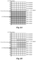
- FIG. 7 explains the number of luma line buffers required for DF, SAO, and ALF with LCU-based decoding.
- lines A-J are first processed by horizontal DF and then by vertical DF.
- lines K-P are first processed by DF, and then lines K-P are processed by SAO.
- SAO is applied to line K
- line J is required. Therefore, one line (J) of DF output pixels has to be stored for SAO.
- the 4 ⁇ 4 block properties for lines I-P are calculated.
- lines I-P can be filtered by ALF. When line I is filtered, it requires lines G-K, as illustrated by the filter shape ( 750 ) and the center of the filter ( 752 ) is indicated. However, calculating block properties of lines I-J still needs lines F-J.
- FIG. 8 explains the number of chroma line buffers required for DF, SAO, and ALF with LCU-based decoding.
- lines A-M are first processed by horizontal DF, and then lines A-L are processed by vertical DF.
- the vertical DF for lines M-N it has to wait for the lower LCU.
- chroma DF reads two H-DF pixels and may write one pixel on each side of the boundary, as illustrated by the 2-pixel stripe.
- one line (M) of H-DF pixels and one line (N) of pre-DF pixels have to be stored for DF.
- SAO is going to be applied on DF output pixels. Since the vertical DF for lines M-N will not change line M, H-DF pixels of line M are also DF output pixels of line M, and SAO can process line L, as illustrated by the 3 ⁇ 3 square ( 820 ).
- ALF can process lines A-J. After this, no further process can be done for the current LCU until the lower LCU comes.
- lines N-P are first processed by horizontal DF, and then lines M-P are processed by vertical DF and by SAO.
- SAO processes line M line L is required.
- lines K-P can be filtered by ALF.
- line K When line K is filtered, it requires lines I-M, as illustrated by the filter shape ( 820 ) with the center of the filter ( 822 ) is indicated. Therefore, four lines (I-L) of SAO output pixels have to be stored for ALF. In total, the entire in-loop filtering requires seven chroma line buffers.
- VBs are upward shifted horizontal LCU boundaries by N pixels.
- FIG. 9 B VBs are left shifted vertical LCU boundaries by N pixels.
- SAO and ALF can process pixels above the VB before the lower LCU comes but cannot process pixels below the VB until the lower LCU comes, which is caused by DF.
- SAO and ALF are modified to ensure that every to-be-processed pixel on one side of a VB does not require any data access from the other side of the VB unless the data can become available in time without using any additional line buffer.
- a method and apparatus for in-loop processing of reconstructed video are disclosed. According to this method, reconstructed pixels associated with a current picture are received, where the current picture is divided into multiple blocks for in-loop processing of the reconstructed pixels.
- a virtual boundary is determined for to-be-processed pixels in the current picture, where the virtual boundary is aligned with block boundaries and at least one to-be-processed pixel on a first side of the virtual boundary requires one or more second pixels on a second side of the virtual boundary.
- the in-loop processing is modified if a target to-be-processed pixel requires at least one second pixel from the second side of the virtual boundary and the modified in-loop processing eliminates the need for any second pixel on the second side of the virtual boundary.
- the multiple blocks correspond to 4 ⁇ 4 blocks. In one embodiment, the multiple blocks correspond to smallest units in which all samples share the same in-loop processing. In one embodiment, the in-loop processing corresponds to SAO (Sample Adaptive Offset) processing or ALF (Adaptive Loop Filter) processing. In one embodiment, the reconstructed pixels correspond to luma pixels. For chroma reconstructed pixels of the current picture, a chroma virtual boundary is allowed to cross chroma blocks.
- SAO Sample Adaptive Offset
- ALF Adaptive Loop Filter
- the target to-be-processed pixel requires any second pixel from the second side of the virtual boundary, such second pixel from the second side of the virtual boundary are padded. In another embodiment, if the target to-be-processed pixel requires any second pixel from the second side of the virtual boundary, such second pixel from the second side of the virtual boundary are padded using symmetric padding.
- modified in-loop processing uses a modified filter with reduced footprint to eliminate the need for any second pixel on the second side of the virtual boundary.
- the modified in-loop processing can be applied to the reconstructed pixels at an encoder side as well as a decoder side.
- an extended block covering the target block is determined for a target block belonging to the to-be-processed pixels.
- Block classification is derived for the target block based on the extended block, where if any target pixel of the extended block required for deriving the block classification is on the second side of the virtual boundary, at least one operation associated with the block classification is modified.
- the adaptive-loop-filter processing is then applied to the target block using the block classification with at least one operation modified if any target pixel of the extended block required for said deriving the block classification is on the second side of the virtual boundary.
- an evaluation block is determined for the target block, wherein the target block is located at a center of the evaluation block and surrounding pixels are added to the evaluation block to form the extended block.
- the target block corresponds to a 4 ⁇ 4 block
- the evaluation block corresponds to an 8 ⁇ 8 block
- the extended block corresponds to a 10 ⁇ 10 block.
- the target block corresponds to the smallest unit in which all samples share an identical adaptive-loop-filter processing.
- the block classification is derived based on gradients at selected locations of the evaluation block.
- the target gradient is excluded from a summation of gradients for the block classification or is set to zero.
- the summation of gradients are normalized by a total number of available gradients at the selected locations of the evaluation block.
- the summation of gradients are weighted according to a total number of available gradients at the selected locations of the evaluation block.
- the target gradient for the target selected location of the evaluation block is modified to exclude said any target pixel of the extended block on the second side of the virtual boundary.
- the selected locations of the evaluation block correspond to 2:1 horizontal sub-sampled locations with one-pixel offset between even lines and odd lines.
- FIG. 1 A illustrates an exemplary adaptive inter/intra video encoding system incorporating DF, SAO and ALF in-loop processing.
- FIG. 1 B illustrates an exemplary adaptive inter/intra video decoding system incorporating DF, SAO and ALF in-loop processing.
- FIG. 2 illustrates an example of deblocking filter process applied on 8 ⁇ 8 block boundaries to reduce the visibility of artefacts at block boundaries, where a vertical boundary and a horizontal boundary are shown.
- FIG. 3 illustrates an example of band offset (BO), where the pixel intensity range is equally divided into 32 bands and an offset value is determined for each band.
- BO band offset
- FIG. 4 illustrates Edge Offset (EO) windows corresponding to 0°, 90°, 135°, and 45° used in HEVC (high efficiency video coding) standard to determine the category for a current pixel to apply SAO (Sample Adaptive Offset).
- EO Edge Offset
- FIG. 5 illustrates an example of adaptive loop filter (ALF), where the ALF has two filter shape options corresponding to cross11 ⁇ 5 and snowflake5 ⁇ 5, for luma and chroma.
- ALF adaptive loop filter
- FIG. 6 A illustrates an example of block adaptation (BA) for adaptive loop filter (ALF), where the BA mode uses edge activity and direction as a property for each 4 ⁇ 4 block.
- BA block adaptation
- ALF adaptive loop filter
- FIG. 6 B illustrates an example of block classification for a target block by evaluating gradients at selected locations of an evaluation block, where the target 4 ⁇ 4 block shown in gray colour is located in the center of the evaluation block.
- FIG. 6 C illustrates an example of 7 ⁇ 7 diamond filter for luma and 5 ⁇ 5 diamond filter for chroma component, where the coefficients are half symmetry across diagonal line.
- FIG. 6 D illustrates an example of the line buffer requirement for ALF in VTM 4.0, where the filter footprint is 7 ⁇ 7 diamond filter for luma and 5 ⁇ 5 diamond filter for chroma.
- FIG. 6 E illustrates an example of the line buffer requirement 4 ⁇ 4 block-based classification for ALF in VTM 4.0, where classification is performed for 4 ⁇ 4 block.
- FIG. 6 F illustrates an example of the concept is when ALF is applied to the pixels at one side of virtual boundary, then the pixels at the other side cannot be used.
- FIG. 7 illustrates an example of the number of luma line buffers required for DF, SAO, and ALF with LCU-based decoding.
- FIG. 8 illustrates an example of the number of chroma line buffers required for DF, SAO, and ALF with LCU-based decoding.
- FIG. 9 A illustrates an example of VBs by upward shifting horizontal LCU boundaries by N pixels.
- FIG. 9 B illustrates an example of VBs by left shifting vertical LCU boundaries by N pixels.
- FIG. 10 illustrates an example VB processing for pixels above the VB, where all pixels of the current LCU have been processed by REC, and four lines (p 0 -p 3 ) of pre-DF pixels are stored in DF line buffers.
- FIG. 11 illustrates an example VB processing for pixels above the VB, where pixels above the VB are processed by horizontal DF.
- FIG. 12 illustrates an example VB processing for pixels above the VB, where pixels above the VB are processed by vertical DF.
- FIG. 13 illustrates an example VB processing for pixels above the VB, where pixels above the VB are going to be processed by SAO.
- FIG. 14 illustrates an example VB processing for pixels above the VB, where all pixels above the VB have been processed by SAO.
- FIG. 15 illustrates an example VB processing for pixels above the VB, where the block properties of lines p 4 -p 7 are directly reused for line p 3 since SAO output pixels of lines p 0 -p 2 are not yet available.
- FIG. 16 illustrates an example VB processing for pixels above the VB, where snowflake5 ⁇ 5 is selected for ALF, SAO output pixels of the last row (line p 2 ) of the snowflake5 ⁇ 5 for filtering line p 4 and the last two rows (lines p 1 -p 2 ) of the snowflake5 ⁇ 5 for filtering line p 3 are not yet available and are replaced by pre-DF pixels.
- FIG. 17 illustrates an example VB processing for pixels above the VB, where cross9 ⁇ 9 is selected for ALF, SAO output pixels of the last row (line p 2 ) of the cross9 ⁇ 9 for filtering line p 6 and the last two rows (lines p 1 -p 2 ) of the cross9 ⁇ 9 for filtering line p 5 are not yet available and are replaced by pre-DF pixels.
- FIG. 18 illustrates an example VB processing for pixels above the VB, where cross9 ⁇ 9 is also selected for ALF, SAO output pixels of the last three rows (lines p 0 -p 2 ) of the cross9 ⁇ 9 for filtering line p 4 are not yet available and are replaced by pre-DF pixels.
- FIG. 19 illustrates an example VB processing for pixels above the VB, where all pixels above the VB have been processed by ALF. At this moment, pixels above the VB can be written to a decoded picture buffer before the lower LCU comes.
- FIGS. 20 - 29 illustrate the proposed luma VB processing for pixels below the VB.
- FIG. 20 illustrates an example VB processing for pixels below the VB, where four lines (i.e., p 0 -p 3 ) of pre-DF pixels can be read from the DF line buffers.
- FIG. 21 illustrates an example VB processing for pixels below the VB, where pixels of line p 3 and pixels below the VB are processed by horizontal DF.
- FIG. 22 illustrates an example VB processing for pixels below the VB, where the pixels below the VB are processed by vertical DF.
- FIG. 23 illustrates an example VB processing for pixels below the VB, where the pixels below the VB are going to be processed by SAO.
- FIG. 24 illustrates an example VB processing for pixels below the VB, where all pixels below the VB (and above the next VB) have been processed by SAO.
- FIG. 25 illustrates an example VB processing for pixels below the VB, where SAO output pixels of line p 3 are replaced by the available DF output pixels.
- FIG. 26 illustrates an example VB processing for pixels below the VB, where for filtering line p 2 , SAO output pixels of the second row (i.e., line p 3 ) of the snowflake5 ⁇ 5 are replaced by DF output pixels; and SAO output pixels of the first row (i.e., line p 4 ) of the snowflake5 ⁇ 5 are replaced by nearest DF output pixels of line p 3 .
- FIG. 27 illustrates an example VB processing for pixels below the VB, where cross9 ⁇ 9 is selected for ALF; for filtering line p 2 , the filter shape is reduced to cross9 ⁇ 3 with adding the six discarded coefficients to the center pixel; and SAO output pixels of the first row (i.e., line p 3 ) of the cross9 ⁇ 3 are replaced by DF output pixels.
- FIG. 28 illustrates an example VB processing for pixels below the VB, where cross9 ⁇ 9 is also selected for ALF; for filtering line p 0 , the filter shape is reduced to cross9 ⁇ 7 with adding the two discarded coefficients to the centre pixel; and SAO output pixels of the first row (i.e., line p 3 ) of the cross9 ⁇ 7 are replaced by DF output pixels.
- FIG. 29 illustrates an example VB processing for pixels below the VB, where all pixels below the VB (and above the next VB) have been processed by ALF.
- FIGS. 30 - 38 show the chroma VB processing for pixels above the VB.
- FIGS. 39 - 47 show the chroma VB processing for pixels below the VB.
- FIG. 48 illustrates a flowchart of an exemplary in-loop processing of reconstructed video according to an embodiment of the present invention.
- FIG. 49 illustrates a flowchart of exemplary adaptive-loop-filter processing of reconstructed video according to an embodiment of the present invention.
- the luma VB processing can be divided into two parts. The first part handles pixels above the VB, while the second part handles pixels below the VB.
- FIGS. 10 - 19 illustrate various proposed luma VB processing for pixels above the VB.
- FIG. 10 all pixels of the current LCU have been processed by REC, and four lines (p 0 -p 3 ) of pre-DF pixels are stored in DF line buffers.
- FIG. 11 pixels above the VB are processed by horizontal DF.
- luma DF reads four pixels and writes up to three pixels on each side of the 8 ⁇ 8 block boundary.
- FIG. 12 pixels above the VB are processed by vertical DF.
- FIG. 13 pixels above the VB are going to be processed by SAO.
- SAO processing of line p 3 may need DF output pixels of line p 2 . Since DF output pixels of line p 2 are not yet available, they are replaced by pre-DF pixels of line p 2 for SAO processing of line p 3 .
- FIG. 14 all pixels above the VB have been processed by SAO.
- FIGS. 15 - 18 pixels above the VB are going to be processed by ALF.
- calculating ALF block properties of line p 3 requires SAO output pixels of lines p 0 -p 4 . Since SAO output pixels of lines p 0 -p 2 are not yet available, the block properties of lines p 4 -p 7 are directly reused for line p 3 , as shown in FIG. 15 .
- SAO output pixels below the VB may also be originally needed. In these cases, SAO output pixels are replaced by pre-DF pixels.
- SAO output pixels of the last row (i.e., line p 2 ) of the snowflake5 ⁇ 5 for filtering line p 4 and the last two rows (i.e., lines p 1 -p 2 ) of the snowflake5 ⁇ 5 for filtering line p 3 are not yet available and are replaced by pre-DF pixels.
- the filter shape is reduced to cross9 ⁇ 7, and the coefficients at the two vertical ends of the original cross9 ⁇ 9 are added to the center pixel. In this way, it is unnecessary to change ALF syntax, and normalization of coefficients with multiplications and divisions can be avoided.
- SAO output pixels of the last three rows (i.e., lines p 0 -p 2 ) of the cross9 ⁇ 7 for filtering line p 3 are not yet available and are replaced by pre-DF pixels.
- FIG. 19 all pixels above the VB have been processed by ALF. At this moment, pixels above the VB can be written to a decoded picture buffer before the lower LCU comes.
- FIGS. 20 - 29 illustrate the proposed luma VB processing for pixels below the VB.
- four lines i.e., p 0 -p 3
- pre-DF pixels can be read from the DF line buffers.
- FIG. 21 pixels of line p 3 and pixels below the VB are processed by horizontal DF.
- calculating horizontal DF decisions of lines p 0 -p 3 requires pre-DF pixels of lines p 0 -p 7 .
- these horizontal DF decisions are computed and stored in a decision line buffer during the horizontal DF for lines p 3 -p 7 in FIG. 11 .
- the decision buffer only requires one bit per 8 ⁇ 8 block and can be simply implemented as on-chip registers or SRAMs.
- FIG. 22 pixels below the VB are processed by vertical DF. Please remember that vertical DF decisions use pre-DF pixels, so the vertical DF decisions at the horizontal LCU boundary have to be calculated before the horizontal DF is done in FIG. 21 .
- FIG. 23 pixels below the VB are going to be processed by SAO. Originally, SAO processing of line p 2 may need DF output pixels of line p 3 . Since DF output pixels of line p 3 are already available, the SAO input pixels are not changed.
- FIG. 24 all pixels below the VB (and above the next VB) have been processed by SAO. In FIGS.
- pixels below the VB are going to be processed by ALF.
- ALF block properties of lines p 0 -p 3 requires SAO output pixels of lines p 0 -p 4 .
- SAO output pixels of lines p 3 -p 4 are not available any more. Therefore, SAO output pixels of line p 3 are replaced by the available DF output pixels, as shown in FIG. 25 .
- repetitive padding in the vertical direction is applied to generate pixels of line p 4 from DF output pixels of line p 3 .
- SAO output pixels above the VB may also be originally needed. In these cases, SAO output pixels are replaced by DF output pixels of line p 3 , and padding or reducing the filter shape may be applied.
- SAO output pixels of the first row (i.e., line p 3 ) of the snowflake5 ⁇ 5 are replaced by DF output pixels.
- the filter shape is reduced to cross9 ⁇ 3 with adding the six discarded coefficients to the center pixel, and SAO output pixels of the first row (i.e., line p 3 ) of the cross9 ⁇ 3 are replaced by DF output pixels.
- the filter shape is reduced to cross9 ⁇ 5 with adding the four discarded coefficients to the center pixel, and SAO output pixels of the first row (i.e., line p 3 ) of the cross9 ⁇ 5 are replaced by the DF output pixels.
- the filter shape is reduced to cross9 ⁇ 7 with adding the two discarded coefficients to the center pixel; and SAO output pixels of the first row (i.e., line p 3 ) of the cross9 ⁇ 7 are replaced by DF output pixels.
- the proposed chroma VB processing has the same concepts and similar principles as the proposed luma VB processing and is summarized in Table 3.
- FIGS. 30 - 38 show the chroma VB processing for pixels above the VB
- FIGS. 39 - 47 show the chroma VB processing for pixels below the VB.
- there is no redundant computation of chroma horizontal DF for line p 1 because the chroma vertical DF does not use any pre-DF pixel and the H-DF pixels of line p 1 are already stored in the line buffer.
- LCU largest coding unit
- CTU coding tree unit
- the position of virtual boundaries should be aligned with the boundaries of smallest units (e.g., 4 ⁇ 4 blocks). Since all of pixels in one 4 ⁇ 4 luma block share the same filter coefficients (i.e., share the same ALF processing), the process of ALF with virtual boundaries becomes simple when virtual boundaries are aligned with the boundaries of 4 ⁇ 4 luma blocks. In other words, all of pixels in one 4 ⁇ 4 luma block should be located at the same side of virtual boundaries. Virtual boundaries cannot partition any 4 ⁇ 4 luma block into two regions. Since there is no classification for chroma component, no constraint related to the position of virtual boundaries for chroma component is required.
- the block-based classification is used to achieve a high coding gain of ALF, those 4 ⁇ 4 blocks above the virtual boundaries or below the virtual boundaries can be treated as different groups compared to the other 4 ⁇ 4 blocks.
- the virtual boundary is set as the boundary between line J and line K.
- the 4 ⁇ 4 blocks in lines G-J and lines K-N are treated as different groups compared to 4 ⁇ 4 blocks in other lines, such as lines C-F.
- the classification rules used to group 4 ⁇ 4 blocks into different categories include the position of 4 ⁇ 4 blocks or virtual boundaries.
- there are original 25 categories for normal 4 ⁇ 4 blocks; those 4 ⁇ 4 blocks above or below the virtual boundaries are classified into another additional 25 categories by using the same classification rules.
- ALF is not applied to these 4 ⁇ 4 blocks above or below the virtual boundaries.
- the decision of disabling ALF for these 4 ⁇ 4 blocks above or below the virtual boundaries is signalled at a sequence level, picture level, tile level or slice level.
- one 10 ⁇ 10 window is required to calculate the block property.
- the required pixel at the other side of virtual boundaries are not used in the process of block property calculation.
- the padding technology is used to generate the required data, including activity, gradient, gradient directions, and so on, when the required pixel are at the other side of virtual boundaries.
- the position of virtual boundaries is the middle position in the vertical direction of one 4 ⁇ 4 luma block.
- Those 4 ⁇ 4 luma blocks cross virtual boundaries e.g. 4 ⁇ 4 blocks in lines G-J in FIG. 7 ) are not filtered by ALF.
- the concept of virtual boundaries is further extended to be one guard band.
- ALF is disabled.
- the pixels below the guard band cannot be used but those pixels in the guard band can be referenced.
- the pixels above the guard band cannot be used but those pixels in the guard band can be referenced.
- the predefined line can be line I or line J.
- the output value of ALF can be the weighted sum of filtered result and the unfiltered pixel.
- the weights for filtered results are decreased when less real pixels are used in the filtering process (i.e. more padded pixels are used in the filtering process).
- the output value of ALF in line G and line N is equal to the filtered result.
- the output value of ALF in line H and line M is equal to ((the filtered result+the unfiltered result)/2).
- the output value of ALF in line I and line L is equal to ((the filtered result+3 ⁇ the unfiltered result)/4).
- the output value of ALF in line J and line K is equal to ((the filtered result+7 ⁇ the unfiltered result)/8).
- the output value of ALF in line G and line N is equal to ((the filtered result+the unfiltered result)/2).
- the output value of ALF in Line H and Line M is equal to (the filtered result+3 ⁇ the unfiltered result)/4.
- the output value of ALF in Line I and Line L is equal to (the filtered result+7 ⁇ the unfiltered result)/8.
- the output value of ALF in line J and line K is equal to (the filtered result+15 ⁇ the unfiltered result)/16.
- the output value of ALF in line G and line N is equal to (4 ⁇ the filtered result+0 ⁇ the unfiltered result)/4.
- the output value of ALF in line H and line M is equal to (3 ⁇ the filtered result+1 ⁇ the unfiltered result)/4.
- the output value of ALF in line I and line L is equal to ((2 ⁇ the filtered result+2 ⁇ the unfiltered result)/4).
- the output value of ALF in line J and line K is equal to ((1 ⁇ the filtered result+3 ⁇ the unfiltered result)/4).
- the rounding offset is considered when generating the weighted sum of the filtered result and the unfiltered result.
- the output value of ALF in line G and line N is equal to ((7 ⁇ the filtered result+1 ⁇ the unfiltered result)/8).
- the output value of ALF in line H and line M is equal to ((5 ⁇ the filtered result+3 ⁇ the unfiltered result)/8).
- the output value of ALF in line I and line L is equal to ((3 ⁇ the filtered result+5 ⁇ the unfiltered result)/8).
- the output value of ALF in line J and line K is equal to ((1 ⁇ the filtered result+7 ⁇ the unfiltered result)/8).
- the rounding offset is considered when generating the weighted sum of the filtered result and the unfiltered result.
- the rounding offset is considered when generating the weighted sum of the filtered result and the unfiltered result.
- the padding technology in the above methods can be direct padding, padding with even mirroring, padding with odd mirroring, some predefined value, to-be-filtered pixel, to-be-filtered pixel row, some intermediate result before ALF process, or some combination of the above.
- the padding technology is to use the symmetric line in the filter shape when the required pixels are unavailable.
- the above methods can be used individually or combined together to achieve one total solution in order to reduce line buffer usage of ALF.
- the required pixels at the other side of virtual boundaries are replaced by the padded samples in ALF process, including classification and filtering operations.
- padding technology is used to generate the required samples for all processes in ALF, instead of accessing the real pixels at the other side of virtual boundaries. For example, when calculating gradients, if some of the required pixels in one 10 ⁇ 10 window used in classification are on the other side of virtual boundaries, then padding technology is used to generate the corresponding pixels.
- the operations of block classification are changed when part of the required pixels in one 10 ⁇ 10 window used in classification are on the other side of virtual boundaries. For example, if part of the required pixels in one 10 ⁇ 10 window used in classification are on the other side of virtual boundaries, then those gradients with position on the other side of virtual boundaries are set as zeros (i.e. not used), then the summation of gradients are normalized by the total number of available gradients. In another example, if part of the required pixels in one 10 ⁇ 10 window used in classification are at the other side of virtual boundaries, then the pattern of required gradients is changed to avoid using those pixels on the other side of virtual boundaries.
- any of the foregoing proposed methods can be implemented in encoders and/or decoders.
- any of the proposed methods can be implemented in an in-loop filtering module of an encoder and/or a decoder.
- any of the proposed methods can be implemented as a circuit coupled to in-loop filtering module of the encoder and/or the decoder.
- FIG. 48 illustrates a flowchart of an exemplary in-loop processing of reconstructed video according to an embodiment of the present invention.
- the steps shown in the flowchart may be implemented as program codes executable on one or more processors (e.g., one or more CPUs) at the encoder side.
- the steps shown in the flowchart may also be implemented based hardware such as one or more electronic devices or processors arranged to perform the steps in the flowchart.
- reconstructed pixels associated with a current picture are received in step 4810 , wherein the current picture is divided into multiple blocks for said in-loop processing of the reconstructed pixels.
- a virtual boundary for to-be-processed pixels in the current picture is determined in step 4820 , wherein the virtual boundary is aligned with block boundaries and at least one to-be-processed pixel on a first side of the virtual boundary requires one or more second pixels on a second side of the virtual boundary.
- Said in-loop processing is modified in step 4830 if a target to-be-processed pixel requires at least one second pixel from the second side of the virtual boundary, wherein said modified in-loop processing eliminates a need for any second pixel on the second side of the virtual boundary.
- FIG. 49 illustrates a flowchart of exemplary adaptive-loop-filter processing of reconstructed video according to an embodiment of the present invention.
- reconstructed pixels associated with a current picture are received in step 4910 , wherein the current picture is divided into multiple blocks for said adaptive-loop-filter processing of the reconstructed pixels.
- a virtual boundary for to-be-processed pixels in the current picture is determined in step 4920 , wherein at least one to-be-processed pixel on a first side of the virtual boundary requires one or more second pixels on a second side of the virtual boundary.
- An extended block covering the target block is determined in step 4930 for a target block belonging to the to-be-processed pixels.
- Block classification is derived for the target block based on the extended block in step 4940 , wherein if any target pixel of the extended block required for said deriving the block classification is on the second side of the virtual boundary, at least one operation associated with the block classification is modified. Said adaptive-loop-filter processing is applied to the target block using the block classification with said at least one operation modified in step 4950 if any target pixel of the extended block required for said deriving the block classification is on the second side of the virtual boundary.
- Embodiment of the present invention as described above may be implemented in various hardware, software codes, or a combination of both.
- an embodiment of the present invention can be one or more circuit circuits integrated into a video compression chip or program code integrated into video compression software to perform the processing described herein.
- An embodiment of the present invention may also be program code to be executed on a Digital Signal Processor (DSP) to perform the processing described herein.
- DSP Digital Signal Processor
- the invention may also involve a number of functions to be performed by a computer processor, a digital signal processor, a microprocessor, or field programmable gate array (FPGA). These processors can be configured to perform particular tasks according to the invention, by executing machine-readable software code or firmware code that defines the particular methods embodied by the invention.
- the software code or firmware code may be developed in different programming languages and different formats or styles.
- the software code may also be compiled for different target platforms.
- different code formats, styles and languages of software codes and other means of configuring code to perform the tasks in accordance with the invention will not depart from the spirit and scope of the invention.
Landscapes
- Engineering & Computer Science (AREA)
- Multimedia (AREA)
- Signal Processing (AREA)
- Compression Or Coding Systems Of Tv Signals (AREA)
Priority Applications (1)
| Application Number | Priority Date | Filing Date | Title |
|---|---|---|---|
| US17/286,713 US11743458B2 (en) | 2018-10-23 | 2019-10-18 | Method and apparatus for reduction of in-loop filter buffer |
Applications Claiming Priority (5)
| Application Number | Priority Date | Filing Date | Title |
|---|---|---|---|
| US201862749145P | 2018-10-23 | 2018-10-23 | |
| US201862750282P | 2018-10-25 | 2018-10-25 | |
| US201862768200P | 2018-11-16 | 2018-11-16 | |
| US17/286,713 US11743458B2 (en) | 2018-10-23 | 2019-10-18 | Method and apparatus for reduction of in-loop filter buffer |
| PCT/CN2019/111895 WO2020083108A1 (fr) | 2018-10-23 | 2019-10-18 | Procédé et appareil pour une réduction de tampon de filtre en boucle |
Publications (2)
| Publication Number | Publication Date |
|---|---|
| US20210360238A1 US20210360238A1 (en) | 2021-11-18 |
| US11743458B2 true US11743458B2 (en) | 2023-08-29 |
Family
ID=70331215
Family Applications (1)
| Application Number | Title | Priority Date | Filing Date |
|---|---|---|---|
| US17/286,713 Active 2040-01-11 US11743458B2 (en) | 2018-10-23 | 2019-10-18 | Method and apparatus for reduction of in-loop filter buffer |
Country Status (5)
| Country | Link |
|---|---|
| US (1) | US11743458B2 (fr) |
| EP (2) | EP3868109A4 (fr) |
| CN (1) | CN113287316B (fr) |
| TW (1) | TWI738092B (fr) |
| WO (1) | WO2020083108A1 (fr) |
Families Citing this family (17)
| Publication number | Priority date | Publication date | Assignee | Title |
|---|---|---|---|---|
| US11044473B2 (en) * | 2018-12-21 | 2021-06-22 | Qualcomm Incorporated | Adaptive loop filtering classification in video coding |
| CN113994671B (zh) * | 2019-06-14 | 2024-05-10 | 北京字节跳动网络技术有限公司 | 基于颜色格式处理视频单元边界和虚拟边界 |
| EP3970366B1 (fr) | 2019-06-14 | 2025-12-10 | Beijing Bytedance Network Technology Co., Ltd. | Manipulation de limites d'unités vidéo et de limites virtuelles |
| CN117478878A (zh) | 2019-07-09 | 2024-01-30 | 北京字节跳动网络技术有限公司 | 用于自适应环路滤波的样点确定 |
| EP3984223A4 (fr) | 2019-07-11 | 2022-11-09 | Beijing Bytedance Network Technology Co., Ltd. | Remplissage d'échantillon dans un filtrage de boucle adaptatif |
| CN117676168A (zh) | 2019-07-15 | 2024-03-08 | 北京字节跳动网络技术有限公司 | 自适应环路滤波中的分类 |
| US11197030B2 (en) | 2019-08-08 | 2021-12-07 | Panasonic Intellectual Property Corporation Of America | System and method for video coding |
| CN120017829A (zh) * | 2019-08-08 | 2025-05-16 | 松下电器(美国)知识产权公司 | 用于视频编码的系统和方法 |
| WO2021049593A1 (fr) | 2019-09-11 | 2021-03-18 | Panasonic Intellectual Property Corporation Of America | Système et procédé de codage vidéo |
| CN117278747A (zh) | 2019-09-22 | 2023-12-22 | 北京字节跳动网络技术有限公司 | 自适应环路滤波中的填充过程 |
| KR102721536B1 (ko) | 2019-09-27 | 2024-10-25 | 베이징 바이트댄스 네트워크 테크놀로지 컴퍼니, 리미티드 | 상이한 비디오 유닛들 간의 적응적 루프 필터링 |
| JP7454042B2 (ja) | 2019-10-10 | 2024-03-21 | 北京字節跳動網絡技術有限公司 | 適応ループ・フィルタリングにおける利用可能でないサンプル位置でのパディング・プロセス |
| US11425405B2 (en) * | 2019-11-15 | 2022-08-23 | Qualcomm Incorporated | Cross-component adaptive loop filter in video coding |
| CN119653115A (zh) * | 2019-12-12 | 2025-03-18 | Lg电子株式会社 | 图像解码和编码方法、数据的传输方法及存储介质 |
| EP4218235A4 (fr) | 2020-09-23 | 2024-04-03 | Beijing Dajia Internet Information Technology Co., Ltd. | Amélioration du codage par chrominance dans un décalage adaptatif d'échantillon inter-composant à limite virtuelle |
| CN113099221B (zh) * | 2021-02-22 | 2023-06-02 | 浙江大华技术股份有限公司 | 跨分量样点自适应补偿方法、编码方法及相关装置 |
| WO2022174773A1 (fr) | 2021-02-22 | 2022-08-25 | Zhejiang Dahua Technology Co., Ltd. | Procédés et systèmes de codage de vidéo |
Citations (9)
| Publication number | Priority date | Publication date | Assignee | Title |
|---|---|---|---|---|
| US20120082244A1 (en) | 2010-10-05 | 2012-04-05 | Mediatek Inc. | Method and Apparatus of Region-Based Adaptive Loop Filtering |
| US20130028531A1 (en) * | 2010-05-18 | 2013-01-31 | Sony Corporation | Image processing device and image processing method |
| US20130044809A1 (en) * | 2011-08-18 | 2013-02-21 | Qualcomm Incorporated | Applying partition-based filters |
| WO2013060250A1 (fr) | 2011-10-24 | 2013-05-02 | Mediatek Inc. | Procédé et appareil de filtrage de boucle non-inter-tuile |
| US20130322523A1 (en) * | 2011-05-10 | 2013-12-05 | Mediatek Inc. | Method and apparatus for reduction of in-loop filter buffer |
| US20140173179A1 (en) | 2012-12-19 | 2014-06-19 | Qualcomm Incorporated | Virtual boundary codes in a data image of a read-write memory device |
| CN105794206A (zh) | 2013-11-15 | 2016-07-20 | 联发科技股份有限公司 | 基于块的自适应环路滤波方法 |
| CN106028050A (zh) | 2011-05-16 | 2016-10-12 | 联发科技股份有限公司 | 用于亮度和色度分量的样本自适应偏移的方法和装置 |
| US20220132117A1 (en) * | 2019-07-09 | 2022-04-28 | Beijing Bytedance Network Technology Co., Ltd. | Sample determination for adaptive loop filtering |
-
2019
- 2019-10-18 CN CN201980068336.2A patent/CN113287316B/zh active Active
- 2019-10-18 EP EP19875755.1A patent/EP3868109A4/fr not_active Withdrawn
- 2019-10-18 WO PCT/CN2019/111895 patent/WO2020083108A1/fr not_active Ceased
- 2019-10-18 EP EP23153780.4A patent/EP4192016A1/fr active Pending
- 2019-10-18 US US17/286,713 patent/US11743458B2/en active Active
- 2019-10-21 TW TW108137854A patent/TWI738092B/zh active
Patent Citations (15)
| Publication number | Priority date | Publication date | Assignee | Title |
|---|---|---|---|---|
| US20130028531A1 (en) * | 2010-05-18 | 2013-01-31 | Sony Corporation | Image processing device and image processing method |
| US20120082244A1 (en) | 2010-10-05 | 2012-04-05 | Mediatek Inc. | Method and Apparatus of Region-Based Adaptive Loop Filtering |
| US20130322523A1 (en) * | 2011-05-10 | 2013-12-05 | Mediatek Inc. | Method and apparatus for reduction of in-loop filter buffer |
| CN103503456A (zh) | 2011-05-10 | 2014-01-08 | 联发科技股份有限公司 | 用于减少环内滤波缓冲区的方法及其装置 |
| CN106028050A (zh) | 2011-05-16 | 2016-10-12 | 联发科技股份有限公司 | 用于亮度和色度分量的样本自适应偏移的方法和装置 |
| US20130044809A1 (en) * | 2011-08-18 | 2013-02-21 | Qualcomm Incorporated | Applying partition-based filters |
| WO2013060250A1 (fr) | 2011-10-24 | 2013-05-02 | Mediatek Inc. | Procédé et appareil de filtrage de boucle non-inter-tuile |
| CN103891292A (zh) | 2011-10-24 | 2014-06-25 | 联发科技股份有限公司 | 非跨图块环路滤波方法及其装置 |
| US20140198844A1 (en) | 2011-10-24 | 2014-07-17 | Mediatek Inc. | Method and apparatus for non-cross-tile loop filtering |
| US20140173179A1 (en) | 2012-12-19 | 2014-06-19 | Qualcomm Incorporated | Virtual boundary codes in a data image of a read-write memory device |
| US9442840B2 (en) | 2012-12-19 | 2016-09-13 | Qualcomm Incorporated | Virtual boundary codes in a data image of a read-write memory device |
| CN104885052A (zh) | 2012-12-19 | 2015-09-02 | 高通股份有限公司 | 读写存储设备的数据映像中的虚拟边界码 |
| CN105794206A (zh) | 2013-11-15 | 2016-07-20 | 联发科技股份有限公司 | 基于块的自适应环路滤波方法 |
| US10567806B2 (en) | 2013-11-15 | 2020-02-18 | Mediatek Inc. | Method of block-based adaptive loop filtering |
| US20220132117A1 (en) * | 2019-07-09 | 2022-04-28 | Beijing Bytedance Network Technology Co., Ltd. | Sample determination for adaptive loop filtering |
Non-Patent Citations (6)
| Title |
|---|
| Chen, C., et al.; "Adaptive Loop Filter with Zero Pixel Line Buffers for LCU-based Decoding" (retrieved on Jul. 15, 2011). |
| Chen, J., et al.; "Algorithm Description of Joint Exploration Test Model 4 (JEM4);" International Organization for Standardization; Nov. 2016; pp. 1-38. |
| Chinese language office action dated Jan. 29, 2021, issued in application No. TW 108137854. |
| Chinese language office action dated Mar. 8, 2023, issued in application No. CN 201980068336.2. |
| Extended European Search Report dated Mar. 27, 2023, issued in application No. EP 23153780.4. |
| International Search Report and Written Opinion dated Jan. 8, 2020, issued in application No. PCT/CN2019/111895. |
Also Published As
| Publication number | Publication date |
|---|---|
| EP3868109A4 (fr) | 2022-08-17 |
| US20210360238A1 (en) | 2021-11-18 |
| EP4192016A1 (fr) | 2023-06-07 |
| CN113287316B (zh) | 2023-07-21 |
| CN113287316A (zh) | 2021-08-20 |
| WO2020083108A1 (fr) | 2020-04-30 |
| TW202023278A (zh) | 2020-06-16 |
| TWI738092B (zh) | 2021-09-01 |
| EP3868109A1 (fr) | 2021-08-25 |
Similar Documents
| Publication | Publication Date | Title |
|---|---|---|
| US11743458B2 (en) | Method and apparatus for reduction of in-loop filter buffer | |
| EP2708027B1 (fr) | Procédé et appareil pour une réduction de tampon de filtre en boucle | |
| US11909965B2 (en) | Method and apparatus for non-linear adaptive loop filtering in video coding | |
| US8913656B2 (en) | Method and apparatus for in-loop filtering | |
| US10003798B2 (en) | Method and apparatus for reduction of deblocking filter | |
| US9967563B2 (en) | Method and apparatus for loop filtering cross tile or slice boundaries | |
| US20140198844A1 (en) | Method and apparatus for non-cross-tile loop filtering | |
| WO2024067188A1 (fr) | Procédé et appareil pour filtre à boucle adaptatif avec classificateurs de chrominance par indices de transposition pour codage vidéo | |
| WO2024016981A1 (fr) | Procédé et appareil pour filtre à boucle adaptatif avec classificateur de chrominance pour codage vidéo | |
| WO2024146624A1 (fr) | Procédé et appareil pour un filtre en boucle adaptatif avec des prises inter-composantes pour le codage vidéo | |
| WO2024088003A1 (fr) | Procédé et appareil de reconstruction sensible à la position dans un filtrage en boucle | |
| EP4588245A1 (fr) | Procédé et appareil pour un filtre en boucle adaptatif avec des prises sans échantillonnage pour le codage vidéo |
Legal Events
| Date | Code | Title | Description |
|---|---|---|---|
| AS | Assignment |
Owner name: MEDIATEK INC., TAIWAN Free format text: ASSIGNMENT OF ASSIGNORS INTEREST;ASSIGNORS:CHEN, CHING-YEH;CHUANG, TZU-DER;SU, YU-CHI;AND OTHERS;SIGNING DATES FROM 20210308 TO 20210310;REEL/FRAME:055961/0098 |
|
| FEPP | Fee payment procedure |
Free format text: ENTITY STATUS SET TO UNDISCOUNTED (ORIGINAL EVENT CODE: BIG.); ENTITY STATUS OF PATENT OWNER: LARGE ENTITY |
|
| STPP | Information on status: patent application and granting procedure in general |
Free format text: DOCKETED NEW CASE - READY FOR EXAMINATION |
|
| AS | Assignment |
Owner name: HFI INNOVATION INC., TAIWAN Free format text: ASSIGNMENT OF ASSIGNORS INTEREST;ASSIGNOR:MEDIATEK INC.;REEL/FRAME:059339/0015 Effective date: 20211201 |
|
| STPP | Information on status: patent application and granting procedure in general |
Free format text: NON FINAL ACTION MAILED |
|
| STPP | Information on status: patent application and granting procedure in general |
Free format text: PUBLICATIONS -- ISSUE FEE PAYMENT RECEIVED |
|
| STCF | Information on status: patent grant |
Free format text: PATENTED CASE |