US11793375B2 - Conversion member and electric cleaner including the same - Google Patents
Conversion member and electric cleaner including the same Download PDFInfo
- Publication number
- US11793375B2 US11793375B2 US16/868,074 US202016868074A US11793375B2 US 11793375 B2 US11793375 B2 US 11793375B2 US 202016868074 A US202016868074 A US 202016868074A US 11793375 B2 US11793375 B2 US 11793375B2
- Authority
- US
- United States
- Prior art keywords
- main body
- handle
- wall
- pipe
- coupled
- Prior art date
- Legal status (The legal status is an assumption and is not a legal conclusion. Google has not performed a legal analysis and makes no representation as to the accuracy of the status listed.)
- Active, expires
Links
- 238000006243 chemical reaction Methods 0.000 title claims abstract description 169
- 239000000428 dust Substances 0.000 claims description 68
- 230000002265 prevention Effects 0.000 claims description 26
- 230000000149 penetrating effect Effects 0.000 claims description 14
- 230000005484 gravity Effects 0.000 abstract description 15
- 230000008878 coupling Effects 0.000 description 233
- 238000010168 coupling process Methods 0.000 description 233
- 238000005859 coupling reaction Methods 0.000 description 233
- 238000003780 insertion Methods 0.000 description 75
- 230000037431 insertion Effects 0.000 description 75
- 238000003825 pressing Methods 0.000 description 34
- 238000004140 cleaning Methods 0.000 description 15
- 238000000034 method Methods 0.000 description 8
- 230000008569 process Effects 0.000 description 6
- RYGMFSIKBFXOCR-UHFFFAOYSA-N Copper Chemical compound [Cu] RYGMFSIKBFXOCR-UHFFFAOYSA-N 0.000 description 5
- 230000008859 change Effects 0.000 description 5
- 238000012986 modification Methods 0.000 description 4
- 230000004048 modification Effects 0.000 description 4
- 239000000463 material Substances 0.000 description 3
- 238000005516 engineering process Methods 0.000 description 2
- 238000004519 manufacturing process Methods 0.000 description 2
- 238000005096 rolling process Methods 0.000 description 2
- 210000003813 thumb Anatomy 0.000 description 2
- 210000000707 wrist Anatomy 0.000 description 2
- 206010063659 Aversion Diseases 0.000 description 1
- 244000007853 Sarothamnus scoparius Species 0.000 description 1
- 230000004308 accommodation Effects 0.000 description 1
- 230000001154 acute effect Effects 0.000 description 1
- 238000004891 communication Methods 0.000 description 1
- 230000000694 effects Effects 0.000 description 1
- 210000003811 finger Anatomy 0.000 description 1
- 239000002210 silicon-based material Substances 0.000 description 1
- 238000010407 vacuum cleaning Methods 0.000 description 1
Images


Classifications
-
- A—HUMAN NECESSITIES
- A47—FURNITURE; DOMESTIC ARTICLES OR APPLIANCES; COFFEE MILLS; SPICE MILLS; SUCTION CLEANERS IN GENERAL
- A47L—DOMESTIC WASHING OR CLEANING; SUCTION CLEANERS IN GENERAL
- A47L9/00—Details or accessories of suction cleaners, e.g. mechanical means for controlling the suction or for effecting pulsating action; Storing devices specially adapted to suction cleaners or parts thereof; Carrying-vehicles specially adapted for suction cleaners
- A47L9/24—Hoses or pipes; Hose or pipe couplings
- A47L9/242—Hose or pipe couplings
-
- A—HUMAN NECESSITIES
- A47—FURNITURE; DOMESTIC ARTICLES OR APPLIANCES; COFFEE MILLS; SPICE MILLS; SUCTION CLEANERS IN GENERAL
- A47L—DOMESTIC WASHING OR CLEANING; SUCTION CLEANERS IN GENERAL
- A47L5/00—Structural features of suction cleaners
- A47L5/12—Structural features of suction cleaners with power-driven air-pumps or air-compressors, e.g. driven by motor vehicle engine vacuum
- A47L5/22—Structural features of suction cleaners with power-driven air-pumps or air-compressors, e.g. driven by motor vehicle engine vacuum with rotary fans
- A47L5/225—Convertible suction cleaners, i.e. convertible between different types thereof, e.g. from upright suction cleaners to sledge-type suction cleaners
-
- A—HUMAN NECESSITIES
- A47—FURNITURE; DOMESTIC ARTICLES OR APPLIANCES; COFFEE MILLS; SPICE MILLS; SUCTION CLEANERS IN GENERAL
- A47L—DOMESTIC WASHING OR CLEANING; SUCTION CLEANERS IN GENERAL
- A47L5/00—Structural features of suction cleaners
- A47L5/12—Structural features of suction cleaners with power-driven air-pumps or air-compressors, e.g. driven by motor vehicle engine vacuum
- A47L5/22—Structural features of suction cleaners with power-driven air-pumps or air-compressors, e.g. driven by motor vehicle engine vacuum with rotary fans
- A47L5/24—Hand-supported suction cleaners
-
- A—HUMAN NECESSITIES
- A47—FURNITURE; DOMESTIC ARTICLES OR APPLIANCES; COFFEE MILLS; SPICE MILLS; SUCTION CLEANERS IN GENERAL
- A47L—DOMESTIC WASHING OR CLEANING; SUCTION CLEANERS IN GENERAL
- A47L5/00—Structural features of suction cleaners
- A47L5/12—Structural features of suction cleaners with power-driven air-pumps or air-compressors, e.g. driven by motor vehicle engine vacuum
- A47L5/22—Structural features of suction cleaners with power-driven air-pumps or air-compressors, e.g. driven by motor vehicle engine vacuum with rotary fans
- A47L5/28—Suction cleaners with handles and nozzles fixed on the casings, e.g. wheeled suction cleaners with steering handle
-
- A—HUMAN NECESSITIES
- A47—FURNITURE; DOMESTIC ARTICLES OR APPLIANCES; COFFEE MILLS; SPICE MILLS; SUCTION CLEANERS IN GENERAL
- A47L—DOMESTIC WASHING OR CLEANING; SUCTION CLEANERS IN GENERAL
- A47L9/00—Details or accessories of suction cleaners, e.g. mechanical means for controlling the suction or for effecting pulsating action; Storing devices specially adapted to suction cleaners or parts thereof; Carrying-vehicles specially adapted for suction cleaners
- A47L9/0009—Storing devices ; Supports, stands or holders
- A47L9/0063—External storing devices; Stands, casings or the like for the storage of suction cleaners
-
- A—HUMAN NECESSITIES
- A47—FURNITURE; DOMESTIC ARTICLES OR APPLIANCES; COFFEE MILLS; SPICE MILLS; SUCTION CLEANERS IN GENERAL
- A47L—DOMESTIC WASHING OR CLEANING; SUCTION CLEANERS IN GENERAL
- A47L9/00—Details or accessories of suction cleaners, e.g. mechanical means for controlling the suction or for effecting pulsating action; Storing devices specially adapted to suction cleaners or parts thereof; Carrying-vehicles specially adapted for suction cleaners
- A47L9/24—Hoses or pipes; Hose or pipe couplings
- A47L9/242—Hose or pipe couplings
- A47L9/246—Hose or pipe couplings with electrical connectors
-
- A—HUMAN NECESSITIES
- A47—FURNITURE; DOMESTIC ARTICLES OR APPLIANCES; COFFEE MILLS; SPICE MILLS; SUCTION CLEANERS IN GENERAL
- A47L—DOMESTIC WASHING OR CLEANING; SUCTION CLEANERS IN GENERAL
- A47L9/00—Details or accessories of suction cleaners, e.g. mechanical means for controlling the suction or for effecting pulsating action; Storing devices specially adapted to suction cleaners or parts thereof; Carrying-vehicles specially adapted for suction cleaners
- A47L9/24—Hoses or pipes; Hose or pipe couplings
- A47L9/248—Parts, details or accessories of hoses or pipes
-
- A—HUMAN NECESSITIES
- A47—FURNITURE; DOMESTIC ARTICLES OR APPLIANCES; COFFEE MILLS; SPICE MILLS; SUCTION CLEANERS IN GENERAL
- A47L—DOMESTIC WASHING OR CLEANING; SUCTION CLEANERS IN GENERAL
- A47L9/00—Details or accessories of suction cleaners, e.g. mechanical means for controlling the suction or for effecting pulsating action; Storing devices specially adapted to suction cleaners or parts thereof; Carrying-vehicles specially adapted for suction cleaners
- A47L9/28—Installation of the electric equipment, e.g. adaptation or attachment to the suction cleaner; Controlling suction cleaners by electric means
- A47L9/2857—User input or output elements for control, e.g. buttons, switches or displays
-
- A—HUMAN NECESSITIES
- A47—FURNITURE; DOMESTIC ARTICLES OR APPLIANCES; COFFEE MILLS; SPICE MILLS; SUCTION CLEANERS IN GENERAL
- A47L—DOMESTIC WASHING OR CLEANING; SUCTION CLEANERS IN GENERAL
- A47L9/00—Details or accessories of suction cleaners, e.g. mechanical means for controlling the suction or for effecting pulsating action; Storing devices specially adapted to suction cleaners or parts thereof; Carrying-vehicles specially adapted for suction cleaners
- A47L9/28—Installation of the electric equipment, e.g. adaptation or attachment to the suction cleaner; Controlling suction cleaners by electric means
- A47L9/2868—Arrangements for power supply of vacuum cleaners or the accessories thereof
- A47L9/2873—Docking units or charging stations
-
- A—HUMAN NECESSITIES
- A47—FURNITURE; DOMESTIC ARTICLES OR APPLIANCES; COFFEE MILLS; SPICE MILLS; SUCTION CLEANERS IN GENERAL
- A47L—DOMESTIC WASHING OR CLEANING; SUCTION CLEANERS IN GENERAL
- A47L9/00—Details or accessories of suction cleaners, e.g. mechanical means for controlling the suction or for effecting pulsating action; Storing devices specially adapted to suction cleaners or parts thereof; Carrying-vehicles specially adapted for suction cleaners
- A47L9/28—Installation of the electric equipment, e.g. adaptation or attachment to the suction cleaner; Controlling suction cleaners by electric means
- A47L9/2894—Details related to signal transmission in suction cleaners
-
- A—HUMAN NECESSITIES
- A47—FURNITURE; DOMESTIC ARTICLES OR APPLIANCES; COFFEE MILLS; SPICE MILLS; SUCTION CLEANERS IN GENERAL
- A47L—DOMESTIC WASHING OR CLEANING; SUCTION CLEANERS IN GENERAL
- A47L9/00—Details or accessories of suction cleaners, e.g. mechanical means for controlling the suction or for effecting pulsating action; Storing devices specially adapted to suction cleaners or parts thereof; Carrying-vehicles specially adapted for suction cleaners
- A47L9/32—Handles
- A47L9/322—Handles for hand-supported suction cleaners
Definitions
- the present disclosure relates to a conversion member and an electric cleaner, and particularly, a conversion member capable of easily changing a center of mass to be at a lower or higher position by being coupled to an existing electric cleaner, and an electric cleaner including the same.
- the vacuum cleaner requires power to drive an electric motor.
- Traditional vacuum cleaners which are corded vacuum cleaners, are operated by connecting a power cord. Accordingly, after a specific room or area is cleaned, a user has to remove a plug from a socket in the area to put the plug into a socket of another area to be cleaned, causing inconvenience.
- a cordless vacuum cleaner powered by a battery has been in the spotlight. This cordless vacuum cleaner is recharged through a charger (or charging unit) when not in use. The user can easily detach the vacuum cleaner for cleaning.
- a main body which is the heaviest member, is located at the bottom. Accordingly, the main body has a moving member such as a wheel, so as to be moved when pulled by the user.
- a main body or cleaner body, which is the heaviest member, is located at an upper or lower position.
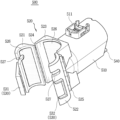
- FIG. 3 is a perspective view of an extension handle included in the electric cleaner of FIG. 1 .
- FIG. 11 is a perspective view illustrating a joint unit included in the electric cleaner of FIG. 1 .
- the dust container 110 has a circular cross section and has a cylindrical shape extending in one direction.
- the dust container 110 may be provided therein with a space and have a shape corresponding to the shape of the main body 100 .
- a hollow portion may be formed inside the main body connector 120 .
- the hollow portion (not shown) may communicate with a hollow portion (not shown) formed in the intake connector 330 , or a hollow portion (not shown) formed inside the pipe 200 .
- a battery (not shown) may be accommodated in the third extended portion 133 .
- the battery (not shown) may be electrically connected to the motor unit (not shown) and the terminal (not shown).
- the third extended portion 133 may have a greater thickness than the first extended portion 131 and the second extended portion 132 .
- the main body electric connection unit 150 may provide electric connection between the main body 100 and the intake port 300 .
- the main body electric connection unit 150 may provide electric connection between the main body 100 and the conversion member 500 .
- the male connector 230 may be inserted into and detachably coupled to the intake connector 330 of the intake port 300 or the conversion connector 510 of the conversion member 500 . It will be understood that the name or designation of the male connector 230 is derived from this coupling or connection scheme.
- the extension handle 400 includes a grip portion 410 , an extension switch 420 , the extension connector 430 , a boss portion 440 , and the extension electric connection unit 450 .
- the grip portion 410 may be a portion of the extension handle 400 designed to be gripped by the user.
- the grip portion 410 may include a first portion 411 and a second portion 412 .
- the extension connector 430 may be inserted into and detachably coupled to the female connector 220 of the pipe 200 .
- the extension electric connection unit 450 and the pipe electric connection unit 240 may be electrically connected to each other.
- the coupling unit 520 may include a first coupling portion (or second wall) 521 , a second coupling portion (or second wall) 522 , a connecting portion (or first wall) 523 , a first hinge part 524 , (or first hinge) and a second hinge part (or second hinge) 525 , a slip prevention portion (or slip prevention layer) 526 , and a penetrating portion (or slot) 527 .
- the first hinge part 524 may be connected to the connecting portion 523 . In detail, of lower ends of the connecting portion 523 , the first hinge part 524 may be connected to one end that faces the first coupling portion 521 . The first hinge part 524 may be connected to the first coupling portion 521 . In detail, the first hinge part 524 may be connected to one end of the first coupling portion 521 that faces the one end of the connecting portion 523 .
- the penetrating portion 527 may allow weight of the entire conversion member 500 to be reduced.
- rigidity of the first coupling portion 521 and the second coupling portion 522 may be enhanced.
- the conversion electric connection unit (or electric connector) 540 may provide electric connection between the conversion member 500 and the main body 100 , or between the conversion member 500 and the pipe 200 .
- the conversion electric connection unit 540 may be provided in a form that allows the electric connection.
- the conversion electric connection unit 540 may be configured as a copper wire.
- One side of the space portion 622 facing the insertion portion 610 namely, a rear side of the space portion 622 is opened in the illustrated embodiment.
- the insertion protrusion 612 may be accommodated in the space portion 622 through the opened side.
- the space portion 622 may extend in a direction toward the intake connector 330 or away from the intake connector 330 , for example, in a front-rear direction by a predetermined length in the illustrated embodiment.
- the predetermined length may be longer than the protruding length of the insertion protrusion 612 .
- FIG. 13 a process in which the housing 310 and the intake connector 330 are rotated relative to each other by the joint unit 600 is illustrated.
- the insertion portion 610 and the accommodating portion 620 are separated from each other.
- the intake connector 330 may be rotated relative to the housing 310 . That is, the intake connector 330 may be rotated clockwise or counterclockwise with respect to the joint unit 600 .
- the electric cleaner 10 may easily change a relative position between the main body 100 and the intake port 300 by using the conversion member 500 . That is, a state in which the main body 100 and the intake port 300 are indirectly connected through the pipe 200 (hereinafter, “up-center state” (high center of gravity)), and a state in which the main body 100 and the intake port 300 are directly connected (hereinafter, “down-center state” (low center of gravity)) may be easily changed to each other.
- up-center state high center of gravity
- down-center state low center of gravity
- the intake port 300 may be located at the lowermost part (or lowest position) of the electric cleaner 10 .
- a lower part of the pipe 200 may be connected to the intake port 300 and an upper part thereof may be connected to the main body 100 . That is, the main body 100 may be located at the uppermost part (or highest position) of the electric cleaner 10 .
- the electric cleaner 10 according to the embodiment of the present disclosure may be recharged by using the stand holder 20 .
- vertical length adjustments of the electric cleaner 10 and the stand holder 20 may be available. Accordingly, when the electric cleaner 10 is in any one of the up-center state and the down-center state, adjustments in length of the stand holder 20 may also be available, as described above.
- the stand holder 20 includes a base 21 , a support (or support rail) 22 , and a charging unit (or charger) 23 .
- the charging unit 23 and the main body 100 may be electrically connected to each other.
- the charging unit 23 may be provided with a pogo pin terminal (not shown).
- a pogo pin electrically connected to the battery (not shown) of the main body 100 may come in contact with a pogo pin of the charging unit 23 so as to be electrically connected to each other.
- the charging unit 23 may be connected to the support 22 .
- a height of the charging unit 23 may be changed as the length of the support 22 is adjusted.
- Embodiments disclosed herein provide a conversion member that may include a conversion connector in which a pipe extending in one direction is detachably inserted, a coupling unit connected to the conversion connector in a direction opposite to the pipe and detachably coupled to a main body having a dust container.
- the coupling unit may include a connecting portion connected to the conversion connector, a first coupling portion rotatably coupled to the connecting portion, and a second coupling portion disposed to face the first coupling portion and rotatably coupled to the connecting portion.
- the coupling unit may include a first hinge part coupled respectively to one side of the connecting portion and one side of the first coupling portion facing the connecting portion, and a second hinge part coupled respectively to one side of the connecting portion and one side of the second coupling portion facing the connecting portion.
- Embodiments disclosed herein also provide an electric cleaner that may include a main body having a dust container, an intake port detachably coupled to one side of the main body, communicating with the dust container and electrically connected to the main body, a conversion member detachably coupled to another side of the main body and electrically connected to the main body, and a pipe detachably coupled to the conversion member and electrically connected to the conversion member.
- the main body may include a handle extending toward the conversion member.
- the conversion member may include a conversion connector in which the pipe is detachably inserted, a coupling unit connected to the conversion connector in a direction opposite to the pipe and detachably coupled to the handle.
- the coupling unit may include a connecting portion connected to the conversion connector, a first coupling portion rotatably coupled to the connecting portion, and a second coupling portion disposed to face the first coupling portion and rotatably coupled to the connecting portion.
- the predetermined angle between the first portion and the second portion of the extension handle may be within a range of 90% to 110% of the predetermined angle between the first extended portion and the second extended portion of the handle. Further, the predetermined angle between the first portion and the second portion of the extension handle may be equal to the predetermined angle between the first extended portion and the second extended portion of the handle.
- the extension handle may be located at the first portion and include an extension switch configured to receive power and a control signal.
- a conversion member is provided to change a position of a main body to be relatively low.
- the main body and the conversion member may be detachably coupled to each other.
- the main body and an intake port are detachably coupled to each other, and the conversion member and a pipe are detachably coupled to each other. That is, even if a position of the main body is located relatively low, adjacent to the intake port, a sufficient length to be gripped by a user can be achieved by the pipe.
- the intake port is detachably coupled with the pipe.
- the main body and the pipe are detachably coupled to each other, the main body may be located at the highest position of an electric cleaner.
- an extension handle may be provided.
- the extension handle is detachably coupled to the pipe to be located at the uppermost part or highest position of the electric cleaner. The user can perform cleaning by gripping the extension handle. Accordingly, even when the main body is located at the lower position, the user can use the electric cleaner by gripping the extension handle. This may result in improving user convenience.
- the intake port, the main body, and the conversion member are electrically connected to one another.
- the user can apply power and a control signal desired by manipulating the main body.
- the conversion member, the pipe, and the extension handle are electrically connected to each other.
- the extension handle is provided with an extension switch. Power and a control signal applied to the extension switch may be transmitted to the main body and the intake port by this electric connection.
- the user can apply power and a control signal for controlling the electric cleaner using the extension switch included in the extension handle. This may result in improving user convenience.
- an insertion protrusion of the insertion portion is fittingly coupled to a space portion of the accommodating portion. Accordingly, the insertion portion and the accommodating portion are not separated from each other unless an external force is applied.
- the housing and the intake connector may be disposed perpendicular to each other. Accordingly, when the insertion portion and the accommodating portion are coupled to each other, the electric cleaner may maintain a self-standing state without a separate mounting member.
- the at least one second wall may include a pair of second walls
- the conversion member may further comprise: a latch rotatably provided at one of the pair of second walls; and a catch provided at another one of the pair of second walls, the latch and the catch may be are configured to be detachably coupled to each other.
Landscapes
- Engineering & Computer Science (AREA)
- Mechanical Engineering (AREA)
- Robotics (AREA)
- Electric Vacuum Cleaner (AREA)
- Motorcycle And Bicycle Frame (AREA)
- Control Of Ac Motors In General (AREA)
Applications Claiming Priority (2)
| Application Number | Priority Date | Filing Date | Title |
|---|---|---|---|
| KR1020190131691A KR102311690B1 (ko) | 2019-10-22 | 2019-10-22 | 변환 부재 및 이를 포함하는 전기 청소기 |
| KR10-2019-0131691 | 2019-10-22 |
Publications (2)
| Publication Number | Publication Date |
|---|---|
| US20210113037A1 US20210113037A1 (en) | 2021-04-22 |
| US11793375B2 true US11793375B2 (en) | 2023-10-24 |
Family
ID=75491903
Family Applications (1)
| Application Number | Title | Priority Date | Filing Date |
|---|---|---|---|
| US16/868,074 Active 2040-11-25 US11793375B2 (en) | 2019-10-22 | 2020-05-06 | Conversion member and electric cleaner including the same |
Country Status (6)
| Country | Link |
|---|---|
| US (1) | US11793375B2 (de) |
| EP (1) | EP4049574A4 (de) |
| KR (1) | KR102311690B1 (de) |
| AU (1) | AU2020371415B2 (de) |
| TW (1) | TWI785340B (de) |
| WO (1) | WO2021080099A1 (de) |
Families Citing this family (6)
| Publication number | Priority date | Publication date | Assignee | Title |
|---|---|---|---|---|
| TWD223038S (zh) * | 2020-08-28 | 2023-01-11 | 南韓商Lg 電子股份有限公司 | 真空吸塵器主體 |
| JP1748158S (ja) * | 2020-08-28 | 2023-07-06 | 掃除機本体 | |
| JP7498967B2 (ja) * | 2021-06-24 | 2024-06-13 | アイリスオーヤマ株式会社 | 電気掃除機システム |
| KR102519103B1 (ko) * | 2021-11-29 | 2023-04-11 | 현대이텔레콤 주식회사 | 살균 기능을 가진 바닥 청소기 |
| JP1823166S (ja) * | 2023-07-18 | 2026-04-01 | 掃除機 | |
| USD1107355S1 (en) * | 2023-07-18 | 2025-12-23 | Lg Electronics Inc. | Vacuum cleaner |
Citations (15)
| Publication number | Priority date | Publication date | Assignee | Title |
|---|---|---|---|---|
| KR200165245Y1 (ko) | 1999-07-21 | 2000-02-15 | 주식회사동양아로나전자 | 핸디형 진공청소기. |
| KR200171783Y1 (ko) | 1999-09-09 | 2000-03-15 | 주식회사동양아로나전자 | 핸디형 진공청소기 |
| JP2005349173A (ja) | 2004-06-09 | 2005-12-22 | Samsung Kwangju Electronics Co Ltd | 延長管支持装置およびこれを備えた真空掃除機 |
| JP2007503932A (ja) | 2003-09-03 | 2007-03-01 | ザ プロクター アンド ギャンブル カンパニー | 多目的洗浄器具 |
| US20080040883A1 (en) * | 2006-04-10 | 2008-02-21 | Jonas Beskow | Air Flow Losses in a Vacuum Cleaners |
| US20100192314A1 (en) * | 2009-02-03 | 2010-08-05 | Makita Corporation | Handy cleaners |
| KR20140034662A (ko) | 2012-09-12 | 2014-03-20 | 주식회사 와이에스테크 | 파이프 길이조절장치 |
| US20140137364A1 (en) * | 2012-11-20 | 2014-05-22 | Dyson Technology Limited | Cleaning appliance |
| JP2015006040A (ja) * | 2013-06-19 | 2015-01-08 | 中国電力株式会社 | 操作棒用フック装置 |
| CN105832246A (zh) * | 2015-01-13 | 2016-08-10 | 科沃斯机器人有限公司 | 真空吸尘器 |
| KR20160128111A (ko) | 2015-04-28 | 2016-11-07 | 삼성전자주식회사 | 핸디 청소기 |
| US20170332858A1 (en) * | 2014-01-06 | 2017-11-23 | H-P Products, Inc. | Central vacuum system and inlet valves therefor |
| WO2018093086A1 (ko) | 2016-11-21 | 2018-05-24 | 삼성전자주식회사 | 청소장치 |
| KR20190030486A (ko) | 2017-09-14 | 2019-03-22 | 엘지전자 주식회사 | 청소기 |
| KR102018521B1 (ko) | 2019-05-29 | 2019-09-09 | 주식회사 브랜뉴인터내셔널 | 상황별 효율적인 청소가 용이한 무선 청소기 |
Family Cites Families (7)
| Publication number | Priority date | Publication date | Assignee | Title |
|---|---|---|---|---|
| EP2359731B1 (de) * | 2006-02-13 | 2016-09-07 | Black & Decker Inc. | Bodenwischer mit freilegbarer Scheuerleiste |
| US9420876B2 (en) * | 2011-07-15 | 2016-08-23 | Sani Products, Inc. | Scraper broom |
| US10729294B2 (en) * | 2013-02-28 | 2020-08-04 | Omachron Intellectual Property Inc. | Hand carryable surface cleaning apparatus |
| TW201733515A (zh) * | 2016-03-22 | 2017-10-01 | 盈太企業股份有限公司 | 組合拖把 |
| JP6332422B1 (ja) | 2016-12-05 | 2018-05-30 | 株式会社Sumco | シリコンウェーハの製造方法 |
| WO2019114965A1 (en) * | 2017-12-14 | 2019-06-20 | Aktiebolaget Electrolux | Vacuum cleaner and valve |
| EP3723570B1 (de) * | 2017-12-15 | 2023-02-08 | Aktiebolaget Electrolux | Staubsauger |
-
2019
- 2019-10-22 KR KR1020190131691A patent/KR102311690B1/ko active Active
-
2020
- 2020-04-10 EP EP20878514.7A patent/EP4049574A4/de active Pending
- 2020-04-10 AU AU2020371415A patent/AU2020371415B2/en active Active
- 2020-04-10 WO PCT/KR2020/004883 patent/WO2021080099A1/ko not_active Ceased
- 2020-05-06 US US16/868,074 patent/US11793375B2/en active Active
- 2020-06-09 TW TW109119353A patent/TWI785340B/zh active
Patent Citations (15)
| Publication number | Priority date | Publication date | Assignee | Title |
|---|---|---|---|---|
| KR200165245Y1 (ko) | 1999-07-21 | 2000-02-15 | 주식회사동양아로나전자 | 핸디형 진공청소기. |
| KR200171783Y1 (ko) | 1999-09-09 | 2000-03-15 | 주식회사동양아로나전자 | 핸디형 진공청소기 |
| JP2007503932A (ja) | 2003-09-03 | 2007-03-01 | ザ プロクター アンド ギャンブル カンパニー | 多目的洗浄器具 |
| JP2005349173A (ja) | 2004-06-09 | 2005-12-22 | Samsung Kwangju Electronics Co Ltd | 延長管支持装置およびこれを備えた真空掃除機 |
| US20080040883A1 (en) * | 2006-04-10 | 2008-02-21 | Jonas Beskow | Air Flow Losses in a Vacuum Cleaners |
| US20100192314A1 (en) * | 2009-02-03 | 2010-08-05 | Makita Corporation | Handy cleaners |
| KR20140034662A (ko) | 2012-09-12 | 2014-03-20 | 주식회사 와이에스테크 | 파이프 길이조절장치 |
| US20140137364A1 (en) * | 2012-11-20 | 2014-05-22 | Dyson Technology Limited | Cleaning appliance |
| JP2015006040A (ja) * | 2013-06-19 | 2015-01-08 | 中国電力株式会社 | 操作棒用フック装置 |
| US20170332858A1 (en) * | 2014-01-06 | 2017-11-23 | H-P Products, Inc. | Central vacuum system and inlet valves therefor |
| CN105832246A (zh) * | 2015-01-13 | 2016-08-10 | 科沃斯机器人有限公司 | 真空吸尘器 |
| KR20160128111A (ko) | 2015-04-28 | 2016-11-07 | 삼성전자주식회사 | 핸디 청소기 |
| WO2018093086A1 (ko) | 2016-11-21 | 2018-05-24 | 삼성전자주식회사 | 청소장치 |
| KR20190030486A (ko) | 2017-09-14 | 2019-03-22 | 엘지전자 주식회사 | 청소기 |
| KR102018521B1 (ko) | 2019-05-29 | 2019-09-09 | 주식회사 브랜뉴인터내셔널 | 상황별 효율적인 청소가 용이한 무선 청소기 |
Non-Patent Citations (3)
| Title |
|---|
| International Search Report dated Jul. 10, 2020 issued in International Application No. PCT/KR2020/004883. |
| Korean Office Action dated Jul. 1, 2021 issued in Application No. 10-2019-0131691. |
| Korean Office Action dated Mar. 5, 2021 issued in Application No. 10-2019-0131691. |
Also Published As
| Publication number | Publication date |
|---|---|
| TW202116243A (zh) | 2021-05-01 |
| KR20210047741A (ko) | 2021-04-30 |
| WO2021080099A1 (ko) | 2021-04-29 |
| US20210113037A1 (en) | 2021-04-22 |
| AU2020371415A1 (en) | 2022-04-14 |
| TWI785340B (zh) | 2022-12-01 |
| EP4049574A1 (de) | 2022-08-31 |
| KR102311690B1 (ko) | 2021-10-12 |
| EP4049574A4 (de) | 2023-11-22 |
| AU2020371415B2 (en) | 2024-03-14 |
Similar Documents
| Publication | Publication Date | Title |
|---|---|---|
| US11793375B2 (en) | Conversion member and electric cleaner including the same | |
| JP7227303B2 (ja) | 格納形態を提供する折り畳み可能な管を備えた電気掃除機 | |
| US11096532B2 (en) | Vacuum cleaner | |
| KR101375653B1 (ko) | 업라이트 및 캐니스터 겸용 진공청소기 | |
| KR101143659B1 (ko) | 컨버터블 진공청소기 | |
| US11445876B2 (en) | Cleaner | |
| KR20130066681A (ko) | 진공 청소기 | |
| WO2007111481A1 (en) | Body of vacuum cleaner and handy type cleaner | |
| AU2009202139B2 (en) | Upright type cleaner | |
| CN202288137U (zh) | 电动吸尘器用软管及电动吸尘器 | |
| CN110179387B (zh) | 一种手持式清洁设备 | |
| AU2019449365B2 (en) | Vacuum cleaner head and electric vacuum cleaner | |
| US7313845B2 (en) | Upright type cleaner | |
| JP2002000516A (ja) | 掃除機 | |
| JP4297595B2 (ja) | 掃除機 | |
| CN114727737A (zh) | 用于真空吸尘器装置的拉动充电附件 | |
| JP7477428B2 (ja) | 電気掃除機 | |
| JP4128809B2 (ja) | 電気掃除機 | |
| KR20160016071A (ko) | 정역회전 청소기 |
Legal Events
| Date | Code | Title | Description |
|---|---|---|---|
| FEPP | Fee payment procedure |
Free format text: ENTITY STATUS SET TO UNDISCOUNTED (ORIGINAL EVENT CODE: BIG.); ENTITY STATUS OF PATENT OWNER: LARGE ENTITY |
|
| AS | Assignment |
Owner name: LG ELECTRONICS INC., KOREA, REPUBLIC OF Free format text: ASSIGNMENT OF ASSIGNORS INTEREST;ASSIGNORS:LEE, SANGCHUL;PARK, JONGIL;LEE, SEUNGYEOP;AND OTHERS;REEL/FRAME:052643/0856 Effective date: 20200427 |
|
| STPP | Information on status: patent application and granting procedure in general |
Free format text: APPLICATION DISPATCHED FROM PREEXAM, NOT YET DOCKETED |
|
| STPP | Information on status: patent application and granting procedure in general |
Free format text: DOCKETED NEW CASE - READY FOR EXAMINATION |
|
| STPP | Information on status: patent application and granting procedure in general |
Free format text: NON FINAL ACTION MAILED |
|
| STPP | Information on status: patent application and granting procedure in general |
Free format text: RESPONSE TO NON-FINAL OFFICE ACTION ENTERED AND FORWARDED TO EXAMINER |
|
| STPP | Information on status: patent application and granting procedure in general |
Free format text: FINAL REJECTION MAILED |
|
| STPP | Information on status: patent application and granting procedure in general |
Free format text: DOCKETED NEW CASE - READY FOR EXAMINATION |
|
| STPP | Information on status: patent application and granting procedure in general |
Free format text: NON FINAL ACTION MAILED |
|
| STPP | Information on status: patent application and granting procedure in general |
Free format text: NOTICE OF ALLOWANCE MAILED -- APPLICATION RECEIVED IN OFFICE OF PUBLICATIONS |
|
| STPP | Information on status: patent application and granting procedure in general |
Free format text: PUBLICATIONS -- ISSUE FEE PAYMENT VERIFIED |
|
| STCF | Information on status: patent grant |
Free format text: PATENTED CASE |