US11795585B2 - Device and method for winding and twisting fiber material in ring spinning or ring twisting frames - Google Patents
Device and method for winding and twisting fiber material in ring spinning or ring twisting frames Download PDFInfo
- Publication number
- US11795585B2 US11795585B2 US17/663,218 US202217663218A US11795585B2 US 11795585 B2 US11795585 B2 US 11795585B2 US 202217663218 A US202217663218 A US 202217663218A US 11795585 B2 US11795585 B2 US 11795585B2
- Authority
- US
- United States
- Prior art keywords
- stators
- ring
- tube
- twisting
- magnetic field
- Prior art date
- Legal status (The legal status is an assumption and is not a legal conclusion. Google has not performed a legal analysis and makes no representation as to the accuracy of the status listed.)
- Active
Links
Images


Classifications
-
- D—TEXTILES; PAPER
- D01—NATURAL OR MAN-MADE THREADS OR FIBRES; SPINNING
- D01H—SPINNING OR TWISTING
- D01H1/00—Spinning or twisting machines in which the product is wound-up continuously
- D01H1/14—Details
- D01H1/16—Framework; Casings; Coverings ; Removal of heat; Means for generating overpressure of air against infiltration of dust; Ducts for electric cables
- D01H1/162—Framework; Casings; Coverings ; Removal of heat; Means for generating overpressure of air against infiltration of dust; Ducts for electric cables for ring type
-
- D—TEXTILES; PAPER
- D01—NATURAL OR MAN-MADE THREADS OR FIBRES; SPINNING
- D01H—SPINNING OR TWISTING
- D01H7/00—Spinning or twisting arrangements
- D01H7/02—Spinning or twisting arrangements for imparting permanent twist
- D01H7/52—Ring-and-traveller arrangements
-
- D—TEXTILES; PAPER
- D01—NATURAL OR MAN-MADE THREADS OR FIBRES; SPINNING
- D01H—SPINNING OR TWISTING
- D01H7/00—Spinning or twisting arrangements
- D01H7/02—Spinning or twisting arrangements for imparting permanent twist
- D01H7/52—Ring-and-traveller arrangements
- D01H7/56—Ring-and-traveller arrangements with freely-rotatable rings; with braked or dragged rings ; Lubricating arrangements therefor
-
- D—TEXTILES; PAPER
- D01—NATURAL OR MAN-MADE THREADS OR FIBRES; SPINNING
- D01H—SPINNING OR TWISTING
- D01H7/00—Spinning or twisting arrangements
- D01H7/02—Spinning or twisting arrangements for imparting permanent twist
- D01H7/04—Spindles
-
- F—MECHANICAL ENGINEERING; LIGHTING; HEATING; WEAPONS; BLASTING
- F16—ENGINEERING ELEMENTS AND UNITS; GENERAL MEASURES FOR PRODUCING AND MAINTAINING EFFECTIVE FUNCTIONING OF MACHINES OR INSTALLATIONS; THERMAL INSULATION IN GENERAL
- F16C—SHAFTS; FLEXIBLE SHAFTS; ELEMENTS OR CRANKSHAFT MECHANISMS; ROTARY BODIES OTHER THAN GEARING ELEMENTS; BEARINGS
- F16C32/00—Bearings not otherwise provided for
- F16C32/04—Bearings not otherwise provided for using magnetic or electric supporting means
- F16C32/0406—Magnetic bearings
- F16C32/0408—Passive magnetic bearings
- F16C32/0436—Passive magnetic bearings with a conductor on one part movable with respect to a magnetic field, e.g. a body of copper on one part and a permanent magnet on the other part
- F16C32/0438—Passive magnetic bearings with a conductor on one part movable with respect to a magnetic field, e.g. a body of copper on one part and a permanent magnet on the other part with a superconducting body, e.g. a body made of high temperature superconducting material such as YBaCuO
-
- F—MECHANICAL ENGINEERING; LIGHTING; HEATING; WEAPONS; BLASTING
- F16—ENGINEERING ELEMENTS AND UNITS; GENERAL MEASURES FOR PRODUCING AND MAINTAINING EFFECTIVE FUNCTIONING OF MACHINES OR INSTALLATIONS; THERMAL INSULATION IN GENERAL
- F16C—SHAFTS; FLEXIBLE SHAFTS; ELEMENTS OR CRANKSHAFT MECHANISMS; ROTARY BODIES OTHER THAN GEARING ELEMENTS; BEARINGS
- F16C2340/00—Apparatus for treating textiles
- F16C2340/18—Apparatus for spinning or twisting
Definitions
- the disclosure relates to a device and to a method than can be applied by the device, which serve for winding and twisting in particular yarns in ring spinning and ring twisting frames.
- Ring spinning technology is the oldest form of fiber spinning and is still used. However, on account of the high quality of the yarn and the flexibility, the ring spinning method is the dominant technique in yarn production. Globally, the use of the ring spinning method is associated with a series of advantages which can barely be replaced by other techniques. Essential advantages are:
- Ring spinning can achieve the largest range of yarn thicknesses, at the highest strength and quality. In contrast thereto, ring spinning is slower than other modern spinning systems such as rotor, friction, nozzle or eddy spinning, and requires more processing steps. The manufacturing limits and productivity is determined by the ring rotor system which, in the case of higher speeds, causes mechanical friction in connection with heating of the rotor or of the strand guide. Consequently, the yarn is burnt, burns through, and tears.
- the virtually frictionless operation allows for high speeds without lubrication, no wear, and no particle formation, even under difficult ambient conditions such as heat, cold, steam, vacuum and aggressive chemicals.
- Spooling and ring twisting devices of a ring spinning or ring twisting frame are known from WO 2012/100964 A1 and WO 2017/178196 A1.
- An annular stator consisting of a superconducting material having a corresponding stator cooling device is used.
- annular stator consisting of a superconducting material having a corresponding stator cooling device is used.
- annular permanent magnetic rotor is used which is arranged so as to be rotatable relative to the stator and so as to be coaxial about the spindle, with a lug-like strand guide element. In this case, an annular axial gap is formed between the stator and the rotor.
- the magnetic flux of the rotor is coupled into the cooled stator and magnetically trapped.
- the rotor is inherently stable above or inside the stator.
- the strand is guided around the rotor from the outside, through the axial gap between the stator and rotor, and wound onto the coil.
- the stator and the rotor have particularly rounded shapes in order that the strand does not encounter any edges which prevent the circulation of the strand in the gap.
- a mechanical support serves for the optimal operating position prior to the magnetization and cooling of the HTS stator.
- the contactless bearing of the rotating rotor eliminates the conventional, frictional heat-generating ring/rotor system as a productivity-limiting component.
- the entire rotor together with the strand guide element is then set into rapid rotation, which is substantially frictionless apart from slight magnetic friction, and thus allows for significantly higher spindle rotational speeds.
- the rotor designed as a magnetic ring has a significant dead weight, which also has to be accelerated when the spindle is started up.
- the freely levitating magnetic ring cannot be encapsulated, and therefore the rotor, running at high rotational speeds of from approximately 20,000 to 30,000 rotations per minute (rpm) constitutes a safety risk for operators of the facility.
- the strand guide element on the magnetic ring rotor constitutes an imbalance, which becomes ever more problematic, on account of vibrations, as the speed of the spindle increases.
- the disclosure provides a device and a method for winding and twisting fibrous material in ring spinning and ring twisting frames, by means of which the operating speed of the frames can be substantially increased, higher productivity during ring spinning can be achieved, and the outlay, in terms of time and material, for assembling and servicing the device can be reduced.
- the solution proposes a superconducting magnetic bearing (SMB) which comprises a permanent magnetic (PM) ring as the rotor, which levitates in a contactless but stable manner, over a superconductor as a cooled stator.
- SMB superconducting magnetic bearing
- PM permanent magnetic
- the relevant rotor is arranged coaxially with respect to the associated spindle, and the strand to be spooled is caused to rotate in the gap between the rotor and stator.
- An efficient and variably adjustable design of the device is achieved in that at least two high-temperature superconducting stators, together with the thermally connected cooling devices thereof, are arranged in a contactless manner and in parallel with one another along the progression of the spindle row, and the magnetic field-generating rotors, oriented coaxially with respect to the spindle, are introduced in a magnetically levitating manner in the magnetic field of the continuous intermediate space, between the stators which are adjacent in each case.
- An additional increase in the stabilisation of the position in the magnetic bearing is achieved if the magnetic field-generating rotors are provided with ferromagnetic magnetic flux collectors which serve to increase the field strength and to guide the magnetic field towards the high-temperature superconductor.
- the high-temperature superconducting stators each consist of at least two bulk HTS elements which are designed so as to be separated from one another, in portions, along the longitudinal extension of the stators, and which are associated with respective magnetic field-generating rotors.
- the high-temperature superconducting stators are formed of material that is joined together in a layered manner, and are designed so as to be strip-like or cable-like in the longitudinal extension thereof.
- a simple and material-saving design of the device is effectively achieved in that the high-temperature superconducting stators are formed of a thermally insulated tube-in-tube configuration, in which the inner “cold” tube, connected to the HTS stator, is of a temperature which is below the superconducting critical temperature, and the outer tube assumes the surrounding ambient temperature.
- the outer tube is made of a material which has a high electrical conductivity suitable for generating eddy currents, and thereby brings about additional magnetic stabilization during the rotational spinning and twisting operation.
- Stable magnetic bearing of the rotors is advantageously achieved in that the stators are in each case formed of a YBaCuO crystal of the composition Y 1 Ba 2 Cu 3 O x (Y123) or a single crystal of the REBaCuO group of the composition RE 1 Ba 2 Cu 3 O x (RE—rare earth) and the superconductors of the bismuth family BiSrCaCuO.
- the solution provided smooths the path for a modular design and collective cooling by means of liquid nitrogen LN2. Furthermore, the HTS material and machine costs are significantly reduced.
- FIG. 1 is a schematic comparative view of the prior and new magnetic bearing and rotors.
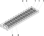
- FIG. 2 is a perspective view of the magnetic bearing comprising three stators-
- FIG. 3 is a cross-sectional view of the magnetic bearing comprising three stators.
- FIG. 4 is a perspective view of the magnetic bearing comprising two stators.
- FIG. 5 is a cross-sectional view of the magnetic bearing comprising two stators.
- FIG. 6 shows the structural internal design of the stator.
- FIG. 7 a schematically shows the additional stabilization of the rotor and FIG. 7 b illustrates its operating principle.
- FIG. 8 a illustrates a centrifugal force curve and FIG. 8 b shows the enveloping bandage of the rotor, for the purpose of compensating the dynamic forces.
- FIG. 1 schematically shows a comparison between the conventional ring single yarn twisting (a) and the HTS high-speed ring spinning method by means of a winding ring and traveler construction suspended magnetically and in a frictionless manner (b).
- the spindles 3 together with the yarn spooled to form coils 5 , are magnetically mounted between two high-temperature superconducting stators 1 that are arranged in parallel.
- annular magnetically mounted magnetic field-generating rotors 2 are used.
- the yarn to be spooled is fed by the feeder system 16 of the machine.
- the difference between the two solutions consists in the design of the magnetic bearing, and the cooling system, required in each case, of the high-temperature superconductor.
- the HTS magnetic bearing is arranged so as to be coaxial to each spindle 3 , and the cooling system is adapted in a complex manner to every individual bearing.
- the magnetic bearing is achieved between two adjacent HTS stators extending along the spindle row.
- the required cooling system is designed so as to allow for simultaneous cooling of all the stators, in a simple manner.
- the perspective view shown in FIG. 2 shows the superconducting magnetic bearing comprising three stators 1 .
- the rotors 2 are designed as permanent magnetic rings having integrated travelers (e.g. lugs).
- the stators 1 provided with high-temperature superconductors (HTS) extend in parallel with one another and along the spindle row.
- the rotors 2 are magnetically mounted in the intermediate space between two adjacent stators 1 in each case. It is furthermore possible, if required, to also arranged further stators 1 in parallel.
- a small tube 8 comprising HTS superconductors arranged thereon, is introduced in the interior of the stators 1 formed as tubes 9 .
- Said superconducting materials 4 are applied, in portions, along the longitudinal extension of the tube 8 such that they achieve the intended position of the relevant rotor 2 .
- the solution provided is adapted, in terms of structure and design, to the conventional ring spinning machines.
- the innovation follows the traditional ring spinning frame design and eliminates the necessity for significant ring spinning frame changes if conventional ring traveler devices are replaced by superconducting magnetic bearings (SMB). In this case, the system operates in a contactless manner and exhibits extremely low rotational friction.
- the free suspension of the rotor combination above the HTS stator 1 , and the rotation thereof at virtually the speed of the spindle, makes it possible for the frictional heat of the rotor 2 to be significantly eliminated, even when the rotor speed is further increased.
- the dynamic process only a low friction force between the strand and traveler is generated.
- the generated rotation of the rotor 2 significantly reduces the strand/traveler frictional interaction, as a result of which the majority of the heat source is eliminated.
- the rotor 2 and the stator 1 are designed such that in each case a circular air gap is formed, so as to be axially spaced between the rotor 2 and the stator 1 and coaxial to the spindle 3 .
- the strand is guided through the rotating traveler, and can be wound onto the rotating coil body.
- the spindles 3 do not have to be kept separate, and have clear space along the spindle row. This construction allows for combined LN2 cooling of a row of corresponding stators 1 having a large free space. Furthermore, in this way spindles 3 and coils can be serviced or replaced much more easily.
- FIG. 3 shows the schematic cross-sectional structure of the magnetic bearing that is formed of three stators 1 .
- the arrangement of the inner tubes 8 in the respective outer tubes 9 is visible.
- the rotors 2 together with the associated spindles 3 in each case, are magnetically suspended in the intermediate space between two adjacent stators 1 in each case.
- the simultaneous cooling of all the superconductors is performed by cooling by means of liquid nitrogen (LN2).
- LN2 liquid nitrogen
- FIG. 4 shows the perspective view of a magnetic bearing consisting of two stators 1 .
- the HTS superconductors 4 are applied to the inner tube 8 , in portions along the longitudinal progression of the stators 1 , and are positioned, in terms of location, such that they magnetically achieve the position of the spindles 3 that is to be assumed.
- the possibility is also provided of designing the HTS superconductors 4 so as to be strip-like or cable-like, which superconductor is applied to the inner tube 8 , over the entire length of the stator 1 , during assembly.
- the HTS superconductor which is generally constructed in a layered manner, is already adapted to the magnetic strengths to be generated, during the prefabrication.
- FIG. 5 A cross-sectional view of the magnetic bearing formed of two stators 1 is visible in FIG. 5 .
- the cooling lines 15 leading into and out of the interior of stators 1 can be seen in the schematic drawing.
- stator 1 The structural internal design of the stator 1 is visible from the illustration of FIG. 6 .
- the square outer tube 9 constitutes the vacuum chamber for the likewise square inner tube 8 .
- the HTS superconductor 4 is adhesively bonded to the inner cold tube 8 .
- Liquid nitrogen, as a coolant, is introduced into the inner tube 8 .
- the magnetic fixing of the inner tube 8 , connected to the HTS superconductor 4 is achieved by means of spacer assemblies 10 consisting of glass fiber structures. These are designed such that they have a heat-conducting connection to the outer tube 9 only at the punctual rests 11 , 12 .
- the bars can consist of a lightweight AL alloy, the design can be constructed in a very compact manner, and at a low weight. Furthermore, the AL alloy material of the cryostat achieves a high thermal connection between the inner tube 8 and the HTS superconductor 4 . However, the high thermal expansion coefficient of the AL alloy at ambient temperature must be taken into account in the determination and fixing of the exact longitudinal position of the superconducting stators 1 in the 4-5 m long carrier elements.
- FIG. 7 The schematic view of an additional stabilization of the position of the rotor 2 is visible in FIG. 7 .
- additional stabilization is achieved by electrical eddy currents 17 which are induced in the cryostat and the stators 1 .
- the inner and outer tube consist of an electrically conductive aluminium alloy.
- the rotating rotor 2 will levitate over a metal Al sheet.
- Two effects can thereby contribute to the stabilization of the rotating rotor 2 .
- Lenz's law the direction of every magnetic induction effect is such that it acts counter to the cause of the effect. As a result, the direction of the magnetic force on the moving magnet is counter to its movement.
- the induced current results in the current status quo being preserved, in that it counteracts the movement or a flux change.
- a lift in the normal direction with respect to the conducting plane, and a resistance braking force counter to the direction of rotation, exist above the stators 1 . Accordingly, both forces contribute to additional retention and stabilization of the rotating rotor 2 during winding and twisting.
- a further embodiment is the generated braking force, which, as a result of the change in the peripheral magnetisation of the annular rotor 2 , brings about rapid braking of the rotating rotor 2 .
- the resistance achieves a maximum and reduces by 1/(v) 1/2 .
- the lift which stabilises the rotor 2 , increases, at a low speed, by v 2 , and overtakes the resistance as the speed increases.
- the graph of FIG. 8 shows the fundamental behavior of the rotors 2 in the case of high-speed ring spinning applications.
- the rotational friction and the dynamic effects of the magnetic bearing are particularly important.
- the essential advantages of superconducting bearings compared with conventional bearings are significant in this field.
- the superconducting passive magnetic bearings exhibit substantially lower friction than conventional rolling bearings, at least by a factor of forty. Even in comparison with pressurised air bearings, the friction of the passive magnetic HTS bearing is in the permille range, and is therefore surprisingly small. This extremely low friction is the physical basis for the innovative ring spinning technology, up to very high spindle rotational speeds.
- centrifugal forces are a further critical point of the ring rotor dynamics.
- the present disclosure focusses on rotational speeds of the permanent magnetic rotor 2 comprising the strand guide of up to 50,000 rpm.
- it is intended to consider the maximum tensile force or force density by way of the tangent vector at the inside radius r i .
- the bandage ring 13 should consist of materials having a high tensile stress, either metal, such as non-magnetic stainless steel, high-strength Al or Mg alloys, or a non-metal ring consisting of glass or carbon fiber compounds.
- metal such as non-magnetic stainless steel, high-strength Al or Mg alloys, or a non-metal ring consisting of glass or carbon fiber compounds.
- the safety ring reinforcement ensures pre-pressure on the rotor 2 even at a speed of zero, and then prevents any cracks or defects of the NdFeB magnetic ring below the nominal operating speeds.
- a safety ring thickness of 3 mm Al alloy AL7075 was selected, and rigidly connected to the rotor 2 by means of thermal shrinkage.
Landscapes
- Engineering & Computer Science (AREA)
- Mechanical Engineering (AREA)
- Textile Engineering (AREA)
- General Engineering & Computer Science (AREA)
- Magnetic Bearings And Hydrostatic Bearings (AREA)
- Spinning Or Twisting Of Yarns (AREA)
- Yarns And Mechanical Finishing Of Yarns Or Ropes (AREA)
- Superconductive Dynamoelectric Machines (AREA)
Applications Claiming Priority (3)
| Application Number | Priority Date | Filing Date | Title |
|---|---|---|---|
| EP21000137.6 | 2021-05-15 | ||
| EP21000137 | 2021-05-15 | ||
| EP21000137.6A EP4089213B1 (de) | 2021-05-15 | 2021-05-15 | Vorrichtung und verfahren zum aufspulen und verdrillen von fasermaterial in ringspinn- oder ringzwirnmaschinen |
Publications (2)
| Publication Number | Publication Date |
|---|---|
| US20220364276A1 US20220364276A1 (en) | 2022-11-17 |
| US11795585B2 true US11795585B2 (en) | 2023-10-24 |
Family
ID=76011662
Family Applications (1)
| Application Number | Title | Priority Date | Filing Date |
|---|---|---|---|
| US17/663,218 Active US11795585B2 (en) | 2021-05-15 | 2022-05-13 | Device and method for winding and twisting fiber material in ring spinning or ring twisting frames |
Country Status (15)
| Country | Link |
|---|---|
| US (1) | US11795585B2 (sr) |
| EP (1) | EP4089213B1 (sr) |
| JP (1) | JP7349531B2 (sr) |
| KR (1) | KR102715004B1 (sr) |
| CN (1) | CN115341312B (sr) |
| BR (1) | BR102022009346A2 (sr) |
| ES (1) | ES2985149T3 (sr) |
| HR (1) | HRP20240568T1 (sr) |
| HU (1) | HUE066501T2 (sr) |
| MA (1) | MA63491B1 (sr) |
| MX (1) | MX2022005853A (sr) |
| PL (1) | PL4089213T3 (sr) |
| RS (1) | RS65456B1 (sr) |
| TN (1) | TN2023000289A1 (sr) |
| WO (1) | WO2022243208A1 (sr) |
Citations (22)
| Publication number | Priority date | Publication date | Assignee | Title |
|---|---|---|---|---|
| US3785140A (en) * | 1969-12-23 | 1974-01-15 | Karlsruhe Augsburg Iweka | Device for winding threads, particularly textile threads |
| US3851448A (en) * | 1972-08-19 | 1974-12-03 | Tory Ind Inc | Yarn twisting apparatus |
| DE4103369A1 (de) | 1990-03-03 | 1991-09-05 | Stahlecker Fritz | Magnetlagerung |
| US5197270A (en) | 1990-06-09 | 1993-03-30 | Fritz Stahlecker | Magnetic bearing system for a spinning machine rotor |
| US5231076A (en) * | 1990-12-15 | 1993-07-27 | Korea Standards Research Institute | Process for manufacturing a YBa2 Cu3 Ox superconductor using infiltration-reaction technique |
| JPH05272539A (ja) | 1992-03-24 | 1993-10-19 | Ntn Corp | 超電導磁気軸受装置 |
| US5330967A (en) * | 1990-07-17 | 1994-07-19 | Koyo Seiko Co., Ltd. | Superconducting bearing device stabilized by trapped flux |
| US5631617A (en) * | 1992-08-25 | 1997-05-20 | Kabushiki Kaisha Toshiba | System for levitating and guiding object by electromagnetic attractive force |
| US5763971A (en) * | 1995-03-16 | 1998-06-09 | Koyo Seiko Co., Ltd. | Superconducting bearing device |
| US6136756A (en) * | 1993-11-30 | 2000-10-24 | Adelwitz Technologiezentrum Gmbh | Method for manufacturing of high temperature superconductor material |
| US6175175B1 (en) * | 1999-09-10 | 2001-01-16 | The University Of Chicago | Levitation pressure and friction losses in superconducting bearings |
| US20020047404A1 (en) * | 2000-07-04 | 2002-04-25 | Norbert Coenen | Rotor spinning device with a contactless, passive, radial bearing for the spinning rotor |
| US20020074882A1 (en) * | 2000-07-13 | 2002-06-20 | Frank Werfel | Centrifuge with a magnetically stabilized rotor for centrifugal goods |
| US6573628B1 (en) * | 1997-09-02 | 2003-06-03 | Rieter Elitex A.S. | Apparatus for spinning-in yarn in a spinning machine |
| WO2008028371A1 (fr) | 2006-08-30 | 2008-03-13 | Jianxin Xu | Dispositif de retordage sans curseur et procédé de retordage associé |
| US20100289200A1 (en) * | 2005-12-16 | 2010-11-18 | Nigata University | Noncontact Rotating Processor |
| WO2012100964A2 (de) | 2011-01-28 | 2012-08-02 | Technische Universität Dresden | Aufspul- und dralleinrichtung einer ringspinn- oder ringzwirnmaschine sowie ringspinn- und ringzwirnverfahren |
| US20150018217A1 (en) * | 2013-07-10 | 2015-01-15 | BenMaan I. Jawdat | HTS Bearing System and Method |
| EP3231904A1 (de) | 2016-04-14 | 2017-10-18 | evico GmbH | Aufspul- und dralleinrichtung einer ringspinn- oder ringzwirnmaschine sowie ringspinn- und ringzwirnverfahren |
| WO2019037836A1 (en) | 2017-08-22 | 2019-02-28 | Evico Gmbh | SUPERCONDUCTING MAGNETIC BEARING HAVING AN ELECTRO-CONDUCTIVE LAYER AS A CURRENT SHOCK ABSORBER |
| EP3812492A1 (en) | 2018-05-23 | 2021-04-28 | Twistperfect, S.L. | Twisting or spinning machine with more than one balloon |
| CN113174666A (zh) | 2021-04-14 | 2021-07-27 | 东华大学 | 具有热隔离作用的高温超导磁悬浮加捻装置 |
Family Cites Families (22)
| Publication number | Priority date | Publication date | Assignee | Title |
|---|---|---|---|---|
| CH337432A (de) * | 1955-03-17 | 1959-03-31 | Spinnerei Karl Marx Veb | Zwirnvorrichtung |
| CH613997A5 (en) * | 1976-09-10 | 1979-10-31 | Kaji Iron Works | Direct two-stage twisting machine |
| JPS56150618A (en) * | 1980-04-22 | 1981-11-21 | Seiko Instr & Electronics Ltd | Magnetic bearing |
| DE59405725D1 (de) * | 1993-06-30 | 1998-05-20 | Forschungszentrum Juelich Gmbh | Spinnvorrichtung und steuer- sowie regeleinrichtung für die spinnvorrichtung |
| US5419982A (en) * | 1993-12-06 | 1995-05-30 | Valence Technology, Inc. | Corner tab termination for flat-cell batteries |
| ES2167420T3 (es) * | 1994-10-03 | 2002-05-16 | Kikuchi Kogyo | Fileta con unidades retorcedoras de doble torsion. |
| KR970008858B1 (ko) * | 1994-10-08 | 1997-05-30 | 이한우 | 자기부상 무부하 이중연사장치 |
| DE69932549T2 (de) * | 1998-07-14 | 2007-07-12 | Murata Kikai K.K. | Mehrfach-Zwirnmaschine des Enzelspindelantrieb-Typs |
| DE19929467A1 (de) * | 1999-06-26 | 2000-12-28 | Rieter Ag Maschf | Sensorik für Ringspinnmaschine |
| DE10049719C1 (de) * | 2000-10-07 | 2001-11-15 | Volkmann Gmbh | Vorrichtung zur Herstellung eines Zwirns in einem integrierten Spinn-Zwirnprozeß |
| JP2002173838A (ja) * | 2000-11-30 | 2002-06-21 | Maruichi Sangyo Kk | カバリングマシンのスピンドル装置 |
| DE10306475A1 (de) * | 2003-02-14 | 2004-08-26 | Deutsche Institute für Textil- und Faserforschung | Fadenführervorrichtung für Ringspindel |
| DE102007010144A1 (de) * | 2007-02-28 | 2008-09-04 | Deutsche Institute für Textil- und Faserforschung Stuttgart | Fadenführeinrichtung für Ringspinnmaschinen |
| CH701482A2 (de) * | 2009-07-16 | 2011-01-31 | Rieter Ag Maschf | Spindellagerung. |
| CN101962833A (zh) * | 2009-07-24 | 2011-02-02 | 王建伟 | Jw导入式磁悬浮倍捻节能锭子 |
| JP5451694B2 (ja) * | 2011-07-05 | 2014-03-26 | 株式会社日立製作所 | 非水電解質電池モジュール |
| DE102011055298A1 (de) * | 2011-11-11 | 2013-05-16 | Deutsche Institute Für Textil- Und Faserforschung Denkendorf | Fadenführeinrichtung für eine ein Vorgarn verspinnende Spinnmaschine |
| CN103313449B (zh) * | 2013-05-14 | 2015-09-09 | 上海超导科技股份有限公司 | 感应加热装置及其感应加热方法 |
| KR102137699B1 (ko) * | 2017-02-23 | 2020-07-24 | 주식회사 엘지화학 | 버스바를 적용한 배터리 셀 |
| CN110552090B (zh) * | 2019-08-21 | 2021-11-05 | 武汉纺织大学 | 一种单锭控制的磁力驱动式加捻装置及其应用 |
| CN110565215B (zh) * | 2019-08-21 | 2022-01-21 | 武汉纺织大学 | 一种气动磁悬式加捻装置及其应用 |
| CN211522419U (zh) * | 2019-11-15 | 2020-09-18 | 北京中科远恒科技有限公司 | 纱线加捻卷绕装置及具有其的环锭纺纱机 |
-
2021
- 2021-05-15 ES ES21000137T patent/ES2985149T3/es active Active
- 2021-05-15 RS RS20240482A patent/RS65456B1/sr unknown
- 2021-05-15 EP EP21000137.6A patent/EP4089213B1/de active Active
- 2021-05-15 HU HUE21000137A patent/HUE066501T2/hu unknown
- 2021-05-15 HR HRP20240568TT patent/HRP20240568T1/hr unknown
- 2021-05-15 PL PL21000137.6T patent/PL4089213T3/pl unknown
-
2022
- 2022-05-13 BR BR102022009346-6A patent/BR102022009346A2/pt active IP Right Grant
- 2022-05-13 JP JP2022079446A patent/JP7349531B2/ja active Active
- 2022-05-13 US US17/663,218 patent/US11795585B2/en active Active
- 2022-05-13 MX MX2022005853A patent/MX2022005853A/es unknown
- 2022-05-15 WO PCT/EP2022/063112 patent/WO2022243208A1/de not_active Ceased
- 2022-05-15 TN TNP/2023/000289A patent/TN2023000289A1/en unknown
- 2022-05-15 MA MA63491A patent/MA63491B1/fr unknown
- 2022-05-16 KR KR1020220059776A patent/KR102715004B1/ko active Active
- 2022-05-16 CN CN202210527001.6A patent/CN115341312B/zh active Active
Patent Citations (26)
| Publication number | Priority date | Publication date | Assignee | Title |
|---|---|---|---|---|
| US3785140A (en) * | 1969-12-23 | 1974-01-15 | Karlsruhe Augsburg Iweka | Device for winding threads, particularly textile threads |
| US3851448A (en) * | 1972-08-19 | 1974-12-03 | Tory Ind Inc | Yarn twisting apparatus |
| DE4103369A1 (de) | 1990-03-03 | 1991-09-05 | Stahlecker Fritz | Magnetlagerung |
| US5197270A (en) | 1990-06-09 | 1993-03-30 | Fritz Stahlecker | Magnetic bearing system for a spinning machine rotor |
| US5330967A (en) * | 1990-07-17 | 1994-07-19 | Koyo Seiko Co., Ltd. | Superconducting bearing device stabilized by trapped flux |
| US5231076A (en) * | 1990-12-15 | 1993-07-27 | Korea Standards Research Institute | Process for manufacturing a YBa2 Cu3 Ox superconductor using infiltration-reaction technique |
| JPH05272539A (ja) | 1992-03-24 | 1993-10-19 | Ntn Corp | 超電導磁気軸受装置 |
| US5631617A (en) * | 1992-08-25 | 1997-05-20 | Kabushiki Kaisha Toshiba | System for levitating and guiding object by electromagnetic attractive force |
| US6136756A (en) * | 1993-11-30 | 2000-10-24 | Adelwitz Technologiezentrum Gmbh | Method for manufacturing of high temperature superconductor material |
| US5763971A (en) * | 1995-03-16 | 1998-06-09 | Koyo Seiko Co., Ltd. | Superconducting bearing device |
| US6573628B1 (en) * | 1997-09-02 | 2003-06-03 | Rieter Elitex A.S. | Apparatus for spinning-in yarn in a spinning machine |
| US6175175B1 (en) * | 1999-09-10 | 2001-01-16 | The University Of Chicago | Levitation pressure and friction losses in superconducting bearings |
| US20020047404A1 (en) * | 2000-07-04 | 2002-04-25 | Norbert Coenen | Rotor spinning device with a contactless, passive, radial bearing for the spinning rotor |
| US20020074882A1 (en) * | 2000-07-13 | 2002-06-20 | Frank Werfel | Centrifuge with a magnetically stabilized rotor for centrifugal goods |
| US20100289200A1 (en) * | 2005-12-16 | 2010-11-18 | Nigata University | Noncontact Rotating Processor |
| WO2008028371A1 (fr) | 2006-08-30 | 2008-03-13 | Jianxin Xu | Dispositif de retordage sans curseur et procédé de retordage associé |
| WO2012100964A2 (de) | 2011-01-28 | 2012-08-02 | Technische Universität Dresden | Aufspul- und dralleinrichtung einer ringspinn- oder ringzwirnmaschine sowie ringspinn- und ringzwirnverfahren |
| US20150018217A1 (en) * | 2013-07-10 | 2015-01-15 | BenMaan I. Jawdat | HTS Bearing System and Method |
| EP3231904A1 (de) | 2016-04-14 | 2017-10-18 | evico GmbH | Aufspul- und dralleinrichtung einer ringspinn- oder ringzwirnmaschine sowie ringspinn- und ringzwirnverfahren |
| WO2017178196A1 (de) | 2016-04-14 | 2017-10-19 | Evico Gmbh | Aufspul- und dralleinrichtung einer ringspinn- oder ringzwirnmaschine sowie ringspinn- und ringzwirnverfahren |
| US20190127892A1 (en) | 2016-04-14 | 2019-05-02 | Sanko Tekstil Isletmeleri San.Ve Tic.A.S. Baspinar Subesi | Spooling and Twisting Device of a Ring-Spinning or Ring-Twisting Machine, and Ring-Spinning and Ring-Twisting Method |
| US10767285B2 (en) * | 2016-04-14 | 2020-09-08 | Sanko Tekstil Isletmeleri San.Ve Tic.A.S. Baspinar Subsei | Spooling and twisting device of a ring-spinning or ring-twisting machine, and ring-spinning and ring-twisting method |
| WO2019037836A1 (en) | 2017-08-22 | 2019-02-28 | Evico Gmbh | SUPERCONDUCTING MAGNETIC BEARING HAVING AN ELECTRO-CONDUCTIVE LAYER AS A CURRENT SHOCK ABSORBER |
| EP3812492A1 (en) | 2018-05-23 | 2021-04-28 | Twistperfect, S.L. | Twisting or spinning machine with more than one balloon |
| EP3812492A4 (en) | 2018-05-23 | 2021-07-21 | Twistperfect, S.L. | TWISTING OR SPINNING MACHINE WITH MORE THAN ONE BALLOON |
| CN113174666A (zh) | 2021-04-14 | 2021-07-27 | 东华大学 | 具有热隔离作用的高温超导磁悬浮加捻装置 |
Non-Patent Citations (8)
| Title |
|---|
| Espenhahn, Tilo, Florian Wunderwald, Marcel Möller, Maria Sparing, Mahmud Hossain, Günter Fuchs, Anwar Abdkader, Chokri Cherif, Kornelius Nielsch, and Ruben Hühne. "Influence of the magnet aspect ratio on the dynamic stiffness of a rotating superconducting magnetic bearing." Journal of Physics D: Applied Physics 53, No. 3 (2019): 035002. |
| Hossain, Mahmud, Anwar Abdkader, Chokri Cherif, Maria Sparing, Dietmar Berger, Günter Fuchs, and Ludwig Schultz. "Innovative twisting mechanism based on superconducting technology in a ring-spinning system." Textile research journal 84, No. 8 (2014): 871-880. |
| Hossain, Mahmud, Christian Telke, Anwar Abdkader, Chokri Cherif, and Michael Beitelschmidt. "Mathematical modeling of the dynamic yarn path depending on spindle speed in a ring spinning process." Textile Research Journal 36, No. 11 (2016): 1180-1190. |
| Rahman, Mustafijur, and Md Golam Nur. "Recent Innovations in Yarn Technology: A Review." International Journal of Scientific and Research Publications 4, No. 6 (2014): 7. |
| Smythe, W. R. "On eddy currents in a rotating disk." Electrical Engineering 61, No. 9 (1942): 681-684. |
| Sparing, M., A. Berger, F. Wall, V. Lux, S. Hameister, D. Berger, M. Hossain et al. "Dynamics of rotating superconducting magnetic bearings in ring spinning." IEEE Transactions on Applied Superconductivity 26, No. 3 (2016): 1-4. |
| Werfel, F. N., U. Flögel-Delor, R. Rothfeld, D. Wippich, and T. Riedel. "Centrifuge advances using HTS magnetic bearings." Physica C: Superconductivity 354, No. 1-4 (2001): 13-17. |
| Xia, Zhigang, and Weilin Xu. "A review of ring staple yarn spinning method development and its trend prediction." Journal of Natural Fibers 10, No. 1 (2013): 62-81. |
Also Published As
| Publication number | Publication date |
|---|---|
| CN115341312B (zh) | 2024-02-09 |
| EP4089213A1 (de) | 2022-11-16 |
| HUE066501T2 (hu) | 2024-08-28 |
| KR20220155418A (ko) | 2022-11-22 |
| EP4089213C0 (de) | 2024-01-31 |
| CN115341312A (zh) | 2022-11-15 |
| JP2022176403A (ja) | 2022-11-28 |
| BR102022009346A2 (pt) | 2022-11-22 |
| ES2985149T3 (es) | 2024-11-04 |
| MX2022005853A (es) | 2022-11-16 |
| HRP20240568T1 (hr) | 2024-08-02 |
| KR102715004B1 (ko) | 2024-10-11 |
| PL4089213T3 (pl) | 2024-06-24 |
| RS65456B1 (sr) | 2024-05-31 |
| EP4089213B1 (de) | 2024-01-31 |
| MA63491A1 (fr) | 2024-01-31 |
| TN2023000289A1 (en) | 2025-07-02 |
| MA63491B1 (fr) | 2025-12-31 |
| US20220364276A1 (en) | 2022-11-17 |
| WO2022243208A1 (de) | 2022-11-24 |
| JP7349531B2 (ja) | 2023-09-22 |
Similar Documents
| Publication | Publication Date | Title |
|---|---|---|
| US6806604B2 (en) | Centrifuge with a magnetically stabilized rotor for centrifugal goods | |
| US6831384B2 (en) | Magnetic bearing | |
| US3648082A (en) | Rotary electrical machines | |
| WO2019037836A1 (en) | SUPERCONDUCTING MAGNETIC BEARING HAVING AN ELECTRO-CONDUCTIVE LAYER AS A CURRENT SHOCK ABSORBER | |
| CN109687635A (zh) | 嵌套转子无铁心飞轮 | |
| CN106972658A (zh) | 磁悬浮超高速永磁电机的转子结构 | |
| US20080001495A1 (en) | Superconducting rotating machines with stationary field coils | |
| US5256637A (en) | Superconducting coil bearings for rotor load | |
| KR101836550B1 (ko) | 초전도 기계용 냉각제 공급 라인의 감쇠식 비접촉 지지를 위한 장치 및 방법 | |
| US11795585B2 (en) | Device and method for winding and twisting fiber material in ring spinning or ring twisting frames | |
| GB2326527A (en) | Superconducting magnet | |
| US7944105B2 (en) | Synchronous machine having magnetic bearings excited by the rotor | |
| US12482587B2 (en) | Magnetic field generating device | |
| JP3665878B2 (ja) | 軸受装置およびその始動方法 | |
| CN116779275A (zh) | 一种用于磁悬浮电磁推进的高温超导磁体及磁悬浮列车 | |
| JP4473470B2 (ja) | 遠心分離物を受容するために設けられているロータを有する遠心分離機 | |
| US12060660B2 (en) | Winding and twisting device for a ring spinning or ring twisting machine | |
| EA048238B1 (ru) | Устройство и способ наматывания и скручивания волокнистого материала кольцепрядильных или кольцекрутильных машин | |
| DE102021002523B4 (de) | Vorrichtung und Verfahren zum Aufspulen und Verdrillen von Fasermaterial in Ringspinn- oder Ringzwirnmaschinen | |
| CN114678183B (zh) | 高强度低漏热支撑结构及具有其的超导磁体 | |
| JP2024132706A (ja) | 超伝導回転機、および、その冷却方法 | |
| Niemann et al. | Cryocooler applications for high-temperature superconductor magnetic bearings | |
| KR101181932B1 (ko) | 와이어 단열을 이용한 초전도 베어링 | |
| US8575808B2 (en) | Electric motor comprising an inductor with a superconducting element incorporated between coils | |
| JP2000060033A (ja) | 超電導エネルギー貯蔵システム |
Legal Events
| Date | Code | Title | Description |
|---|---|---|---|
| FEPP | Fee payment procedure |
Free format text: ENTITY STATUS SET TO UNDISCOUNTED (ORIGINAL EVENT CODE: BIG.); ENTITY STATUS OF PATENT OWNER: LARGE ENTITY |
|
| STPP | Information on status: patent application and granting procedure in general |
Free format text: DOCKETED NEW CASE - READY FOR EXAMINATION |
|
| STPP | Information on status: patent application and granting procedure in general |
Free format text: RESPONSE TO NON-FINAL OFFICE ACTION ENTERED AND FORWARDED TO EXAMINER |
|
| STPP | Information on status: patent application and granting procedure in general |
Free format text: NOTICE OF ALLOWANCE MAILED -- APPLICATION RECEIVED IN OFFICE OF PUBLICATIONS |
|
| STPP | Information on status: patent application and granting procedure in general |
Free format text: PUBLICATIONS -- ISSUE FEE PAYMENT RECEIVED |
|
| STPP | Information on status: patent application and granting procedure in general |
Free format text: PUBLICATIONS -- ISSUE FEE PAYMENT VERIFIED |
|
| STCF | Information on status: patent grant |
Free format text: PATENTED CASE |