US11812865B2 - Control mechanism for a chair - Google Patents
Control mechanism for a chair Download PDFInfo
- Publication number
- US11812865B2 US11812865B2 US17/432,173 US202017432173A US11812865B2 US 11812865 B2 US11812865 B2 US 11812865B2 US 202017432173 A US202017432173 A US 202017432173A US 11812865 B2 US11812865 B2 US 11812865B2
- Authority
- US
- United States
- Prior art keywords
- support plate
- base plate
- handle
- control mechanism
- stop
- Prior art date
- Legal status (The legal status is an assumption and is not a legal conclusion. Google has not performed a legal analysis and makes no representation as to the accuracy of the status listed.)
- Active, expires
Links
- 230000007246 mechanism Effects 0.000 title claims abstract description 130
- 230000008878 coupling Effects 0.000 claims description 11
- 238000010168 coupling process Methods 0.000 claims description 11
- 238000005859 coupling reaction Methods 0.000 claims description 11
- 230000000694 effects Effects 0.000 claims description 3
- 239000000463 material Substances 0.000 description 4
- 229910000831 Steel Inorganic materials 0.000 description 3
- 239000010959 steel Substances 0.000 description 3
- 229920001169 thermoplastic Polymers 0.000 description 3
- 239000004416 thermosoftening plastic Substances 0.000 description 3
- XAGFODPZIPBFFR-UHFFFAOYSA-N aluminium Chemical compound [Al] XAGFODPZIPBFFR-UHFFFAOYSA-N 0.000 description 2
- 229910052782 aluminium Inorganic materials 0.000 description 2
- 230000002401 inhibitory effect Effects 0.000 description 2
- 238000000465 moulding Methods 0.000 description 2
- 239000004033 plastic Substances 0.000 description 2
- 229920003023 plastic Polymers 0.000 description 2
- 238000004026 adhesive bonding Methods 0.000 description 1
- 230000006835 compression Effects 0.000 description 1
- 238000007906 compression Methods 0.000 description 1
- 238000010276 construction Methods 0.000 description 1
- 230000001419 dependent effect Effects 0.000 description 1
- 238000006073 displacement reaction Methods 0.000 description 1
- 230000005484 gravity Effects 0.000 description 1
- 210000003205 muscle Anatomy 0.000 description 1
- NJPPVKZQTLUDBO-UHFFFAOYSA-N novaluron Chemical compound C1=C(Cl)C(OC(F)(F)C(OC(F)(F)F)F)=CC=C1NC(=O)NC(=O)C1=C(F)C=CC=C1F NJPPVKZQTLUDBO-UHFFFAOYSA-N 0.000 description 1
- 210000004197 pelvis Anatomy 0.000 description 1
Images



Classifications
-
- A—HUMAN NECESSITIES
- A47—FURNITURE; DOMESTIC ARTICLES OR APPLIANCES; COFFEE MILLS; SPICE MILLS; SUCTION CLEANERS IN GENERAL
- A47C—CHAIRS; SOFAS; BEDS
- A47C9/00—Stools for specified purposes
- A47C9/002—Stools for specified purposes with exercising means or having special therapeutic or ergonomic effects
-
- A—HUMAN NECESSITIES
- A47—FURNITURE; DOMESTIC ARTICLES OR APPLIANCES; COFFEE MILLS; SPICE MILLS; SUCTION CLEANERS IN GENERAL
- A47C—CHAIRS; SOFAS; BEDS
- A47C3/00—Chairs characterised by structural features; Chairs or stools with rotatable or vertically-adjustable seats
- A47C3/18—Chairs or stools with rotatable seat
Definitions
- the present invention relates to a control mechanism for a chair.
- the present invention relates to a control mechanism for a chair which enables a chair seat to be tilted in various directions.
- the present invention relates furthermore to a chair comprising the control mechanism.
- Chairs for example office-type chairs, may include mechanisms for adjusting a seating position, for example a height adjustment of the chair seat, and an adjustment of an inclination of the chair seat and a chair back. These chair adjustments allow the user to change the sitting position in the chair as desired, such that fatigue may be minimized during long sitting periods.
- Fatigue may also be reduced, when the chair seat is freely tiltable in any direction or in some directions. Such a tilting is also called 3D wobbling.
- a tiltable chair seat may be tilted upon displacement of the center of gravity of the user sitting on the chair, and the tiltable chair seat may be urged back automatically to its initial non-tilted position by an elastic element, for example springs.
- an elastic element for example springs.
- a control mechanism for a chair comprises a base plate, which is configured to be coupled to a chair base assembly, and a support plate, which is configured to be coupled to a chair seat.
- the control mechanism comprises furthermore an elastic element which is arranged between the base plate and the support plate.
- the elastic element enables the support plate to be tilted with respect to the base plate around a first tilt axis and a second tilt axis.
- the second tilt axis is different from the first tilt axis.
- the elastic element may be made of a rubber material or injected thermoplastic. In other words, the elastic element enables the support plate to be tilted with respect to the base plate such that a chair seat coupled to the support plate may be inclined in any direction.
- the control mechanism further comprises a control handle configured to be actuated in an actuating direction.
- the control mechanism comprises at least one stop element.
- Each stop element of the at least one stop element is arranged between the base plate and the support plate and configured to limit a minimum distance between the base plate and the support plate at the position of the corresponding stop element.
- a stop element adjust mechanism of the control mechanism is coupled to the control handle and configured to adjust the minimum distance of each stop element of the at least one stop element in response to actuating the control handle in the actuating direction.
- at least one stop element preferably a plurality of stop elements, is provided.
- Each stop element is adjustable under control of the stop element adjust mechanism and the control handle. Adjusting a stop element causes that the stop element limits the minimum distance between the base plate and the support plate at the position of the stop element.
- the base plate and the support plate may be coupled to each other such that the distance between a center of the base plate and a center of the support plate is limited.
- the support plate is coupled to the base plate via a retaining bolt at the centers thereof. Now, the support plate may be inclined with respect to the base plate by a user sitting on the chair seat. This results in a reduced distance between the support plate and the base plate at a particular position.
- the stop element may be arranged at this particular position and may limit the minimum distance at the particular position such that the amount the support plate may be inclined with respect to the base plate may be enlarged or reduced depending on the stop element.
- an inclination of the support plate with respect to the base plate may be enabled or disabled in certain directions.
- inclination of the support plate with respect to the base plate may be enabled or disabled for particular directions, or may be enabled in all directions, or may be disabled in all directions.
- the elastic element will force back the support plate to the starting position.
- a user sitting on the chair can thus adjust the chair seat such that it is fixed in the starting position, elastically tiltable in only one direction or a restricted area of directions, or elastically tiltable in any direction such that a three-dimensional movement of the chair seat is enabled.
- the chair seat is elastically tiltable in one or more directions, an active sitting on the chair seat may be promoted as the user may have to balance when sitting on the chair. This may cause the movement of the pelvis area and may contribute to strengthen the back muscles at the same time. Further fatigue may be reduced.
- each stop element of the at least one stop element extends from the base plate towards the support plate and is configured to be separately displaceable between a retracted position and an extended position. In the extended position, the stop element is located further towards the support plate than in the retracted position. Displacing the stop element may be performed by a stop element adjust mechanism. For example, in the extended position, the stop element may be moved by the stop element adjust mechanism to such an extent in the direction of the support plate that it abuts against the support plate thus inhibiting that the support plate can be moved closer to the base plate at the position of the corresponding stop element. Thus, the minimum distance between the support plate and the base plate is limited by the stop element at the position of the stop element. This may reduce the ability of the support plate to be inclined or tilted in the direction at the corresponding stop element. With a plurality of stop elements arranged at different locations, the tilting of the support plate in certain directions may be enabled, disabled, or restricted.
- a number of stop elements in the extended position may depend on an extent the control handle is actuated in the actuating direction. Thus, by actuating the control handle in the actuating direction the number of stop elements in the extended position may be increased, which reduces the directions in which the support plate may be tilted.
- the control mechanism may comprise four stop elements.
- the control handle is configured to be actuated in the actuating direction in a first handle position, a second handle position and a third handle position.
- In the first handle position all four stop elements are in the retracted position.
- In the second handle position to stop elements are in the retracted position and the other two stop elements are in the extended position.
- In the third handle position all four stop elements are in the extended position.
- one stop element may be arranged in the front area of the chair seat
- one stop element may be arranged in the rear area of the chair seat
- one stop element may be arranged in the left area of the chair seat
- one stop element may be arranged in the right area of the chair seat.
- the chair seat In the first handle position, when all stop elements are in the retracted position, the chair seat may be tiltable in any direction.
- the chair seat In the second handle position, when for example the stop elements in the left area and the right area are in the extended position and the stop elements in the front area and the rear area are in the retracted position, the chair seat may be tiltable in the front/rear direction only, and may not be tilted in the left/right direction anymore.
- the chair seat In the third handle position, when all four stop elements are in the extended position, the chair seat may not be tiltable in any direction.
- the stop element adjust mechanism comprises a rotatable angular plate.
- the rotatable annular plate may be arranged such that a center of the angular plate is essentially aligned to a pole or gas cylinder of the chair base assembly and may be rotatable around this center.
- At least one wedge element extends from the annular plate.
- a corresponding wedge element may be provided at the angular plate.
- Each wedge element is assigned to a corresponding stop element. The minimum distance limited by each stop element is adjusted by the assigned wedge element upon rotating the annular plate.
- the stop element may be arranged with an upper end facing the support plate and the lower end facing the angular plate.
- each wedge element may provide a ramp surface on which a lower end of the assigned stop element is sliding such that the movement of the wedge element in one direction may urge the assigned stop element in the extended position, and a movement of the wedge element in the opposite direction may release the assigned stop element in the retracted position.
- the stop element adjust mechanism comprises a corresponding wedge element for each stop element, with a single control handle the above described states of tilt possibilities may be configured.
- the plurality of stop elements may be arranged equidistant along the annular plate.
- the elastic element may comprise for example an elastic ring.
- the elastic ring may be arranged such that a center of the elastic ring is essentially aligned to a longitudinal axis of the pole or gas cylinder of the chair base assembly, and may essentially be aligned to a center of the rotatable annular plate.
- a first face of the elastic ring may be molded to the base plate and a second face of the elastic ring opposing the first face may be molded to the support plate.
- a coupling element providing a pivotable coupling of the base plate and the support plate may be provided.
- the coupling element may be arranged in a central position of the elastic ring.
- the coupling element may inhibit rotation of the support plate with respect to the base plate around the central position.
- the coupling element may limit the maximum distance between the support plate and the base plate at the coupling position, for example at the centers of the support plate and the base plate.
- a vertical direction may be defined with respect to a chair standing on a ground, i.e. the vertical direction extends from the ground in an upright direction.
- the vertical direction is defined by a direction in which the chair base assembly, the base plate, the support plate and the chair seat are subsequently arranged.
- the first tilt axis may extend essentially perpendicular to the vertical direction
- the second tilt axis may extend essentially perpendicular to the vertical direction and the first tilt axis.
- the chair base assembly may enable a rotation of the base plate around the vertical direction.
- the chair seat may be rotatable/tiltable in all three spatial dimensions, i.e. rotatable around the vertical direction and tiltable around the first and second tilt axes.
- the control mechanism may furthermore comprise an anti-rotation element arranged between the base plate and the support plate.
- the anti-rotation element is configured to prohibit a rotation of the support plate with respect to the base plate around the vertical direction.
- control handle has a longitudinal shape.
- a proximal end of the control handle is coupled to the base plate and the control handle extends from the base plate.
- the control mechanism is configured such that actuating the control handle in the actuating direction comprises moving a distal end of the control handle in the circumferential direction around the vertical direction.
- moving the distal end of the control handle in the circumferential direction may be easily translated in a rotational movement of the rotatable annular plate, i.e. the stop element adjust mechanism, which drives the stop elements.
- the chair base assembly comprises a height control mechanism configured to enable the chair seat of the chair to be displaced in the vertical direction.
- the control handle is configured to be activated in a further actuating direction. Actuating the control handle in the further actuating direction effects actuating the height control mechanism. Actuating the control handle in the further actuating direction comprises moving the distal end of the control handle in the vertical direction.
- the height control mechanism may comprise a gas cylinder mechanism or other lifting mechanism supported by the chair base assembly. For raising or lowering the chair seat, the control handle may be moved upwards or downwards in the vertical direction, whereas configuring the released tilt directions of the chair seat is accomplished by moving the control handle in the horizontal circumferential direction.
- the control mechanism may furthermore comprises an annular cover element attached to the circumferential edge of the support plate.
- the annular cover element further extends to the circumferential edge of the base plate.
- the annular cover element may therefore cover in particular the stop elements, the elastic element and the stop element adjust mechanism for aesthetic reasons.
- the cover element may prohibit that the users finger may be placed between the base plate and the support plate, thus permitting that the finger may be clamped or pinched between the base plate and the support plate when tilting the support plate with respect to the base plate.
- the control mechanism may comprise furthermore an indexing mechanism.
- the indexing mechanism may comprise an elastic index element and three index detents provided at the stop element adjustment mechanism such that the elastic index element engages with a first index detent of the three index detents in the first handle position, engages with a second index detent of the three index detents in the second handle position, and engages with a third index detent of the three index detents in the third handle position.
- the control handle may be reliably moved and held in the first, second and third handle positions.
- a chair comprising a chair base assembly, a chair seat and a control mechanism.
- the control mechanism comprises a base plate, which is coupled to the chair base assembly, and a support plate, which is coupled to the chair seat.
- the control mechanism comprises furthermore an elastic element which is arranged between the base plate and the support plate. The elastic element enables the support plate to be tilted with respect to the base plate around a first tilt axis and a second tilt axis, which is different from the first tilt axis.
- the control mechanism comprises further a control handle configured to be actuated in an actuating direction. Furthermore, the control mechanism comprises at least one stop element.
- Each stop element of the at least one stop element is arranged between the base plate and the support plate and configured to limit a minimum distance between the base plate and the support plate at the position of the corresponding stop element.
- a stop element adjust mechanism of the control mechanism is coupled to the control handle and configured to adjust the minimum distance of each stop element of the at least one stop element in response to actuating the control handle in the actuating direction. Adjusting a stop element causes that the stop element limits the minimum distance between the base plate and the support plate at the position of the stop element.
- an inclination of the support plate with respect to the base plate may be enabled, disabled or restricted in certain directions.
- a user sitting on the chair can adjust the chair seat such that it is fixed in the starting position, elastically tiltable in only one direction or a reduced area of directions, or elastically tiltable in any direction such that a three-dimensional movement of the chair seat is enabled.
- the chair seat is elastically tiltable in one or more directions, an active sitting on the chair seat may be promoted as the user may have to balance when sitting on the chair.
- the control mechanism may be the control mechanism of any aspects or embodiments of the invention.
- control mechanism and the chair according to embodiments may be utilized for various applications, for example, the control mechanism may be utilized in an office chair.
- FIG. 1 is a schematic view of a chair having a control mechanism according to an embodiment.
- FIG. 2 is a schematic perspective view of a control mechanism according to an embodiment.
- FIG. 3 is another schematic perspective view of the control mechanism of FIG. 2 .
- FIG. 4 is a schematic partial perspective view of the control mechanism of FIG. 2 .
- FIG. 5 is a schematic cross-sectional side view of the control mechanism of FIG. 2 .
- FIG. 6 is another schematic cross-sectional side view of the control mechanism of FIG. 2 .
- FIG. 7 illustrates a schematic top view and a schematic side view of the control mechanism of FIG. 2 in a first handle position.
- FIG. 8 illustrates a schematic top view and a schematic side view of the control mechanism of FIG. 2 in a second handle position.
- FIG. 9 illustrates a schematic top view and a schematic side view of the control mechanism of FIG. 2 in a third handle position.
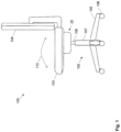
- FIG. 1 shows schematically a chair 100 , for example an office chair, which includes the control mechanism 20 .
- the chair 100 has a chair base assembly 102 and a superstructure.
- the superstructure includes a chair seat 103 , a chair back 104 and components to interconnect the seat 103 with the chair back 104 .
- the base assembly 102 includes a pedestal column 107 , a number of support legs 105 extending radially from the column 107 and a corresponding number of casters 106 supported on the outer ends of the support legs 105 .
- a gas cylinder 108 or another lifting mechanism may be supported by the column 107 to enable the height of the seat 103 , and thus of the chair superstructure, to be adjusted by a user.
- forward refers to a direction moving away from the back 104 and in front of a chair occupant along an axis which extends parallel to such a flat support surface
- rearward refers to a direction opposite to the forward direction
- the term “lateral” refers to a generally horizontal direction perpendicular to both the forward and rearward direction and extending parallel to the aforementioned flat support surface.
- the attachment between a base plate of the control mechanism 20 and the chair base assembly 102 also defines which plane of the control mechanism 20 will be oriented horizontally in the installed state of the control mechanism 20 .
- the control mechanism 20 enables the seat 103 to be tilted in the forward/rearward direction as indicated by arrow 110 in FIG. 1 , and additionally the control mechanism 20 enables the seat 103 to be tilted in the lateral direction, i.e. to the left and to the right.
- the control mechanism 20 may enable the chair seat 103 to be tilted simultaneously in the forward/rearward direction and the lateral direction. Furthermore, the column 107 in combination with the gas cylinder 108 may enable the seat 103 to be rotated around an axis in the vertical direction. Thus, a three-dimensional movement of the chair seat 103 may be enabled. Furthermore, the control mechanism 20 may be adjusted upon actuation of a control handle of the control mechanism 20 by the user to restrict the tilt capabilities of the seat 103 in the forward/rearward direction and left/right direction.
- FIG. 2 shows a perspective view of the control mechanism 20 .
- the control mechanism 20 comprises a support plate 22 , which may be coupled to the chair seat 103 .
- a plurality of holes may be provided and the chair seat 103 may be mounted to the support plate 22 using corresponding bolts.
- the support plate 22 may be made of steel, aluminum or plastics.
- the control mechanism 20 comprises furthermore a base plate 21 , which may be coupled to the chair base assembly 102 .
- the base plate 21 may be made of steel, aluminum or plastics.
- a cover 27 may be mounted at the support plate 22 .
- the cover 27 may have the annular shape and may extend from the support plate 22 to the base plate 21 thus covering components arranged between the base plate 21 and the support plate 22 . Furthermore, the cover 27 may prevent that fingers of a user get in the space between the support plate 22 and the base plate 21 and get pinched or may otherwise interfere with components arranged between the support plate 22 and the base plates 21 . Furthermore, the control mechanism 20 comprises a control handle 24 which is extending radially from the center of the control mechanism 20 .
- FIG. 3 shows a further perspective view of the control mechanism 20 , viewed from a bottom side of the control mechanism 20 .
- the cover 27 completely covers the space between the base plate 21 and the support plate 22 .
- the base plate 21 comprises a connection part 33 for coupling the base plate 21 to the chair base assembly 102 , for example to the gas cylinder 108 .
- the control handle 24 is movable in two directions. First, the distal end of the control handle 24 may be moved in the vertical direction as indicated by arrow 36 . When moving the control handle 24 for example in the upward direction, the gas cylinder 108 may be activated such that the height of the chair seat 103 may be adjusted.
- control handle 24 may be moved such that the distal and of the control handle is moving along a horizontal circular path as indicated by arrow 34 .
- a cutout 35 in the base plate 21 limits the circular path along which the control handle 24 may be moved.
- FIG. 4 shows schematically a partially cutaway perspective view of the control mechanism 20 .
- the connection port 33 of the base plate 31 is coupled to the gas cylinder 108 provided in the column 107 .
- a stop element adjust mechanism 28 is arranged at the base plate 21 .
- the stop element adjust mechanism 28 has an annular form.
- the stop element adjustment mechanism 28 may be rotatable around a vertical central axis 37 .
- the stop element adjustment mechanism 28 is coupled to the control handle 24 through the cutout 35 such that the stop element adjustment mechanism 28 may be rotated under control of the control handle 24 .
- the stop element adjustment mechanism 28 is provided with four wedge elements 38 (only two wedge elements are visible in FIG. 4 ), each providing a ramping section and a plateau.
- stop element 26 A- 26 D is assigned to each wedge element 38 (only stop elements 26 A, 26 C and 26 D are visible in FIG. 4 , stop element 26 B is arrange at a diametrically opposite to stop element 26 A).
- the stop elements 26 A- 26 D do not rotate together with the stop element adjustment mechanism 28 such that, upon rotation of the stop element adjustment mechanism 28 , the wedge element 38 moves relative to the assigned stop element 26 A- 26 D.
- the stop element adjustment mechanism 28 is rotated in the clockwise direction, the stop element 26 A- 26 D comes in contact with the ramping section of the assigned wedge element 38 and the stop element 26 A- 26 D moves upwards in the vertical direction until it reaches the plateau of the wedge element 38 .
- the stop elements 26 A- 26 D are guided in corresponding guides provided in a conical limiter element 32 , which is fixed at the base plate 21 .
- the assigned stop element 26 A- 26 D may be either be in an extended position, in which it protrudes upwards from the conical limiter element 32 , or may be in a retracted position, in which it does not protrude from the conical limiter element 32 .
- An elastic element 23 is arranged between the base plate 21 and the support plate 22 .
- the elastic element 23 enables the support plate 22 to be tilted with respect to the base plate 21 by elastic compression of the elastic element 23 .
- the elastic element 23 may have an annular shape and may be arranged concentrically to the central axis 37 .
- the elastic element 23 may be made of rubber material or injected thermoplastic. As long as the stop elements 26 A- 26 D are not protruding from the conical limiter element 32 , the support plate 22 may be tilted around any horizontal axis until it abuts against the conical limiter element 32 .
- a stop element 26 A- 26 D limits the minimum distance between the support plate 22 and the base plate 21 when tilting the support plate 22 in a vertical downwards direction at the location of the corresponding stop element 26 A- 26 D.
- the four stop elements 26 A- 26 D may be arranged equidistant along the ring shaped form of the conical limiter element 32 , for example a first stop element 26 C may be arranged at the forward side of the chair seat, a second stop element 26 D may be arranged at the rearward side of the chair seat, the third stop element 26 B may be arranged at the left side of the chair seat, and a fourth stop element 26 A may be arranged at the right side of the chair seat (as seen by a user chair 100 ).
- the support plate 22 may only be tilted in the forwarded and rearward direction, but not in the lateral direction anymore. In case all for stop elements 26 A- 26 D are in their extended positions, the support plate 22 may not be tiltable anymore in any direction.
- the cover 27 is mounted at the support plate 22 and extends to the base plate 21 such that it at least partially overlaps an edge of the base plate 21 .
- the cover 27 may not be fixed to the base plate 21 as it may move together with the support plate 22 when the support plate 22 is tilting.
- FIG. 5 shows a sectional view of the control mechanism 20 along a vertical lateral sectional plane.
- the stop element adjust mechanism 28 is in a position, in which at least two stop elements, for example the third stop element 26 B at the right side of the chair seat 103 and the fourth stop element 26 A at the left side of the chair seat 103 , are in their extended positions such that upper ends of the stop elements 26 A, 26 B abut against the lower surface of the support plate 22 , thus inhibiting a tilting of the support plate 22 in the left/right direction.
- control handle 24 is coupled to the gas cylinder 108 such that the gas cylinder 108 may be actuated upon moving the control handle 24 in an upward vertical direction as indicated by arrow 36 .
- the elastic element 23 may be made of rubber material or injected thermoplastic.
- the elastic element 23 may have a shape of a ring. A lower surface of the elastic ring may be glued or molded to the base plate 21 and an upper surface of the elastic ring may be glued or molded to the support plate 22 . Thus, the support plate 22 cannot rotated with respect to the base plate 21 and cannot be removed from the base plate 21 .
- a pivot element 29 may be provided at the base plate 21 and a bolt 30 may extend through the support plate 22 into the pivot element 29 such that the support plate 22 is tiltable mounted to the base plate 21 .
- an anti-rotating element 31 may be provided between the base plate 21 and the support plate 22 such that the rotation of the support plate 22 around the central axis 37 with respect to the support plate 21 is inhibited.
- FIG. 6 shows a sectional view of the control mechanism 20 along a vertical forward/rearward sectional plane.
- the other two stop elements i.e. for example the first stop element 26 C and second stop element 26 D
- the stop elements 26 C, 26 D are not in the ramped up extended position and do therefore not protrude from the conical limiter element 32 .
- control mechanism 20 is shown in a top view and a side view.
- the top view shows the control mechanism 20 as seen in a vertical top-down direction such that the support plate 22 is visible.
- the support plate 22 is partially transparent such that components below the support plate 22 are visible, in particular the stop elements 26 A- 26 D.
- the side view shows the control mechanism 20 as seen from for example the right side as defined above.
- the cover 27 and the base plate 21 are omitted in the side view such that internal details of the control mechanism 20 are more clearly visible, in particular the stop elements 26 A- 26 D, the wedge elements 38 , the conical limiter element 32 , the stop element adjust mechanism 28 , and the elastic element 23 .
- FIG. 7 shows the control mechanism 20 in a first handle position of the control handle 24 .
- the control handle 24 is coupled to the stop element adjust mechanism 28 such that upon moving the control handle 24 in the direction of arrow 34 the stop element adjust mechanism 28 is also rotated around the central axis 37 .
- the stop element adjust mechanism 28 is arranged with respect to the stop elements 26 A- 26 D such that none of the stop elements 26 A- 26 D is ramped up by the wedge elements 38 . Therefore, all stop elements 26 A- 26 D are in the retracted position and do not protrude from the conical limiter element 32 . This enables the support plate 22 to be elastically tilted in any direction by compressing the elastic element 23 .
- FIG. 8 shows the control mechanism 20 in a second handle position of the control handle 24 .
- the control handle 24 is moved in a clockwise direction from the first handle position. Due to the arrangement of the wedge elements 38 at the stop element adjust mechanism 28 , in this second handle position two stop elements 26 A and 26 B are in their extended ramped up position, whereas the other two stop elements 26 C and 26 D are still in their retracted position.
- the left stop element 26 B and the right stop element 26 A are in the extended position and the stop elements 26 C and 26 D in the forward and backward direction are still in their retracted positions.
- the left and right stop elements 26 A, 26 B may be ramped up such that the distance between the upper surface of these stop elements 26 A, 26 B and a lower surface of the support plate 22 is reduced, preferably such that the upper surfaces of these stop elements 26 A, 26 B abut against the lower surface of the support plate 22 .
- the support plate 22 and the chair seat 103 can be tilted in the forward and backward direction only in this second handle position.
- FIG. 9 shows the control mechanism 20 in the third handle position of the control handle 24 .
- the control handle 24 is moved in a clockwise direction from the second handle position. Due to the arrangement of the wedge elements 38 at the stop element adjust mechanism 28 , in this third handle position, all four stop elements 26 A- 26 D are in their extended ramped up position.
- the stop elements 26 A- 26 D may be ramped up such that the distance between the upper surfaces of the stop elements 26 A- 26 D and a lower surface of the support plate 22 is reduced, preferably such that the upper surfaces of the stop elements 26 A- 26 D abut against the lower surface of the support plate 22 .
- the support plate and the chair seat arranged thereon cannot be tilted anymore in any direction.
- the wedge elements 38 may not be arranged equidistant along the stop element adjust mechanism 28 , but such that a first pair of wedge elements 38 is arranged diametrical at the stop element adjustment mechanism 28 , and a second pair of wedge elements 38 is arranged diametrical in a turning angle other than 90° with respect to the first pair of wedge elements 38 , for example in a turning angle of 60° to 80°, in particular 70°.
- control handle 24 may be actuated in the vertical direction (see arrow 36 in FIG. 5 ) to adjust the height of the chair seat 103 . Therefore, only one control handle 24 is required for performing two different adjustments.
- the chair back 104 may be coupled to the chair seat 103 such that the chair back 104 is tilted together with the chair seat 103 .
- the chair back 104 may be coupled to the base plate 21 such that the chair back 104 remains in its position while the chair seat 103 is tilted.
- control mechanism 20 described above comprises an elastic ring as the elastic element 23
- the elastic element 23 may comprise other materials, for example one or more spring elements, for example steel springs.
- control mechanism 20 and the chair 100 are not limited to this particular application. Rather, embodiments of the invention may be employed to effect a three-dimensional tilting or wobbling of a chair seat in a wide variety of chairs.
Landscapes
- Chairs Characterized By Structure (AREA)
- Chairs For Special Purposes, Such As Reclining Chairs (AREA)
Applications Claiming Priority (3)
| Application Number | Priority Date | Filing Date | Title |
|---|---|---|---|
| EP19159655 | 2019-02-27 | ||
| EP19159655.0A EP3701839B1 (fr) | 2019-02-27 | 2019-02-27 | Mécanisme de commande pour chaise |
| PCT/EP2020/053766 WO2020173715A1 (fr) | 2019-02-27 | 2020-02-13 | Mécanisme de commande pour siège |
Publications (2)
| Publication Number | Publication Date |
|---|---|
| US20220183468A1 US20220183468A1 (en) | 2022-06-16 |
| US11812865B2 true US11812865B2 (en) | 2023-11-14 |
Family
ID=65628640
Family Applications (1)
| Application Number | Title | Priority Date | Filing Date |
|---|---|---|---|
| US17/432,173 Active 2040-03-09 US11812865B2 (en) | 2019-02-27 | 2020-02-13 | Control mechanism for a chair |
Country Status (6)
| Country | Link |
|---|---|
| US (1) | US11812865B2 (fr) |
| EP (1) | EP3701839B1 (fr) |
| CN (1) | CN113507867B (fr) |
| CA (1) | CA3124731C (fr) |
| PL (1) | PL3701839T3 (fr) |
| WO (1) | WO2020173715A1 (fr) |
Cited By (3)
| Publication number | Priority date | Publication date | Assignee | Title |
|---|---|---|---|---|
| US12108882B2 (en) * | 2021-10-01 | 2024-10-08 | Kokuyo Co., Ltd. | Chair having a movable seat |
| US12114784B2 (en) * | 2021-10-01 | 2024-10-15 | Kokuyo Co., Ltd. | Chair having a movable seat |
| US12245702B2 (en) * | 2021-10-01 | 2025-03-11 | Kokuyo Co., Ltd. | Chair having a movable seat |
Citations (12)
| Publication number | Priority date | Publication date | Assignee | Title |
|---|---|---|---|---|
| US4441220A (en) * | 1982-01-15 | 1984-04-10 | Peterson Lester W | Recreational apparatus |
| US6688689B1 (en) * | 1999-06-24 | 2004-02-10 | Lord Corporation | Multiple degree of freedom seat suspension system |
| DE202009011789U1 (de) | 2009-08-28 | 2009-12-31 | Müller, Gerhard | Sitzträger für Sitzmöbel und Stehhilfen für ergonomische-dynamisches Sitzen |
| US7686396B2 (en) * | 2006-09-29 | 2010-03-30 | Corewerks, Inc. | Method and apparatus to enhance proprioception and core health of the human body |
| US7922247B2 (en) * | 2008-04-18 | 2011-04-12 | Spark Innovations, Inc. | Hydraulic adjustable seat |
| US20110278418A1 (en) * | 2010-05-14 | 2011-11-17 | National Taiwan University Of Science And Technology | Seat |
| US20120306249A1 (en) * | 2010-01-13 | 2012-12-06 | Dae Hoon Jung | Multifunctional chair |
| US9192236B2 (en) * | 2012-07-27 | 2015-11-24 | Kgm Gaming Llc | Guard and combination for rotatable or swivel seat and method of installing same |
| US9289067B2 (en) * | 2011-05-12 | 2016-03-22 | Stephan Meyer | Piece of seating furniture |
| US9661929B1 (en) * | 2016-01-25 | 2017-05-30 | Harvest-Excel International Pte. Ltd. | Topple-proof buffering structure for a chair |
| US10213024B2 (en) * | 2014-10-28 | 2019-02-26 | Iii Solutions Gmbh | Office, work and leisure chair and retrofit kit for a chair or a seat surface for causing subliminal movements of the person sitting thereon |
| US10433644B2 (en) * | 2016-08-18 | 2019-10-08 | Quali Co., Ltd. | Tiltable stool and tiltable lounge chair |
Family Cites Families (6)
| Publication number | Priority date | Publication date | Assignee | Title |
|---|---|---|---|---|
| AU547268B2 (en) * | 1981-10-28 | 1985-10-10 | Pledge Office Chairs Ltd. | Tilting mechanism for a chair |
| CN85105204A (zh) * | 1985-07-08 | 1987-01-14 | Hag公司 | 椅座或类似器件的倾侧机构 |
| US7066538B2 (en) * | 2003-12-30 | 2006-06-27 | Hni Technologies, Inc. | Chair with tilt lock mechanism |
| DE102005017143B4 (de) * | 2005-04-13 | 2007-06-21 | Bock 1 Gmbh & Co. Kg | Vorrichtung zur Sitzneigeverstellung eines Stuhles |
| CN106314224B (zh) * | 2015-06-17 | 2018-07-27 | 上汽通用五菱汽车股份有限公司 | 一种座椅手动调节腿托机构 |
| NL2019227B1 (en) * | 2017-07-11 | 2019-01-25 | Maxi Miliaan Bv | A child vehicle seat as well as an inlay for such a child vehicle seat |
-
2019
- 2019-02-27 EP EP19159655.0A patent/EP3701839B1/fr active Active
- 2019-02-27 PL PL19159655.0T patent/PL3701839T3/pl unknown
-
2020
- 2020-02-13 CN CN202080016663.6A patent/CN113507867B/zh active Active
- 2020-02-13 WO PCT/EP2020/053766 patent/WO2020173715A1/fr not_active Ceased
- 2020-02-13 US US17/432,173 patent/US11812865B2/en active Active
- 2020-02-13 CA CA3124731A patent/CA3124731C/fr active Active
Patent Citations (12)
| Publication number | Priority date | Publication date | Assignee | Title |
|---|---|---|---|---|
| US4441220A (en) * | 1982-01-15 | 1984-04-10 | Peterson Lester W | Recreational apparatus |
| US6688689B1 (en) * | 1999-06-24 | 2004-02-10 | Lord Corporation | Multiple degree of freedom seat suspension system |
| US7686396B2 (en) * | 2006-09-29 | 2010-03-30 | Corewerks, Inc. | Method and apparatus to enhance proprioception and core health of the human body |
| US7922247B2 (en) * | 2008-04-18 | 2011-04-12 | Spark Innovations, Inc. | Hydraulic adjustable seat |
| DE202009011789U1 (de) | 2009-08-28 | 2009-12-31 | Müller, Gerhard | Sitzträger für Sitzmöbel und Stehhilfen für ergonomische-dynamisches Sitzen |
| US20120306249A1 (en) * | 2010-01-13 | 2012-12-06 | Dae Hoon Jung | Multifunctional chair |
| US20110278418A1 (en) * | 2010-05-14 | 2011-11-17 | National Taiwan University Of Science And Technology | Seat |
| US9289067B2 (en) * | 2011-05-12 | 2016-03-22 | Stephan Meyer | Piece of seating furniture |
| US9192236B2 (en) * | 2012-07-27 | 2015-11-24 | Kgm Gaming Llc | Guard and combination for rotatable or swivel seat and method of installing same |
| US10213024B2 (en) * | 2014-10-28 | 2019-02-26 | Iii Solutions Gmbh | Office, work and leisure chair and retrofit kit for a chair or a seat surface for causing subliminal movements of the person sitting thereon |
| US9661929B1 (en) * | 2016-01-25 | 2017-05-30 | Harvest-Excel International Pte. Ltd. | Topple-proof buffering structure for a chair |
| US10433644B2 (en) * | 2016-08-18 | 2019-10-08 | Quali Co., Ltd. | Tiltable stool and tiltable lounge chair |
Non-Patent Citations (1)
| Title |
|---|
| International Search Report an Written Opinion dated Feb. 27, 2020 in Application No. PCT/EP2020/053766, 12 pages. |
Cited By (3)
| Publication number | Priority date | Publication date | Assignee | Title |
|---|---|---|---|---|
| US12108882B2 (en) * | 2021-10-01 | 2024-10-08 | Kokuyo Co., Ltd. | Chair having a movable seat |
| US12114784B2 (en) * | 2021-10-01 | 2024-10-15 | Kokuyo Co., Ltd. | Chair having a movable seat |
| US12245702B2 (en) * | 2021-10-01 | 2025-03-11 | Kokuyo Co., Ltd. | Chair having a movable seat |
Also Published As
| Publication number | Publication date |
|---|---|
| CA3124731A1 (fr) | 2020-09-03 |
| US20220183468A1 (en) | 2022-06-16 |
| CA3124731C (fr) | 2023-09-26 |
| CN113507867B (zh) | 2024-09-17 |
| EP3701839B1 (fr) | 2022-11-16 |
| CN113507867A (zh) | 2021-10-15 |
| EP3701839A1 (fr) | 2020-09-02 |
| WO2020173715A1 (fr) | 2020-09-03 |
| PL3701839T3 (pl) | 2023-03-13 |
Similar Documents
| Publication | Publication Date | Title |
|---|---|---|
| CA3124731C (fr) | Mecanisme de commande pour siege | |
| US7922247B2 (en) | Hydraulic adjustable seat | |
| CN108289547B (zh) | 可倾斜的凳子或可倾斜的休闲椅 | |
| US11006751B2 (en) | Chair tilt mechanism | |
| US7029071B2 (en) | Office chair | |
| US6685268B2 (en) | Seat arrangement for sitting furniture | |
| US9289067B2 (en) | Piece of seating furniture | |
| JP6775015B2 (ja) | 椅子及び座の支持機構 | |
| US9625015B2 (en) | Pivoting mechanism with gross and fine resistance adjustment | |
| JP2014501568A (ja) | 抵抗支持機構 | |
| US20170252242A1 (en) | Medical chair | |
| CN110313743A (zh) | 椅子椅座的向前倾斜组件 | |
| KR102084357B1 (ko) | 의자의 요추받침대 | |
| US20230329440A1 (en) | Multiple sitting position chair | |
| US11058220B2 (en) | Desk with seating | |
| US20240382001A1 (en) | Chair and furniture composition | |
| JP4217116B2 (ja) | 座のスライド機構 | |
| CN113133604B (zh) | 用于坐具的支撑件 | |
| EP4335324B1 (fr) | Mécanisme d'inclinaison pour chaise | |
| KR102321996B1 (ko) | 좌판모듈 틸팅이 가능한 의자 | |
| KR20250037668A (ko) | 레일이 달린 의자 | |
| KR20220089830A (ko) | 임의 방향으로 좌판의 틸팅이 가능한 의자 | |
| GB2644413A (en) | An adjustable chair | |
| WO2022195636A1 (fr) | Système de posture assise | |
| JP2005021211A (ja) | 椅子 |
Legal Events
| Date | Code | Title | Description |
|---|---|---|---|
| FEPP | Fee payment procedure |
Free format text: ENTITY STATUS SET TO UNDISCOUNTED (ORIGINAL EVENT CODE: BIG.); ENTITY STATUS OF PATENT OWNER: LARGE ENTITY |
|
| AS | Assignment |
Owner name: L&P PROPERTY MANAGEMENT COMPANY, CALIFORNIA Free format text: ASSIGNMENT OF ASSIGNORS INTEREST;ASSIGNOR:COSTAGLIA, MASSIMO;REEL/FRAME:057500/0784 Effective date: 20210813 |
|
| STPP | Information on status: patent application and granting procedure in general |
Free format text: DOCKETED NEW CASE - READY FOR EXAMINATION |
|
| STPP | Information on status: patent application and granting procedure in general |
Free format text: RESPONSE TO NON-FINAL OFFICE ACTION ENTERED AND FORWARDED TO EXAMINER |
|
| STPP | Information on status: patent application and granting procedure in general |
Free format text: ALLOWED -- NOTICE OF ALLOWANCE NOT YET MAILED |
|
| STPP | Information on status: patent application and granting procedure in general |
Free format text: NOTICE OF ALLOWANCE MAILED -- APPLICATION RECEIVED IN OFFICE OF PUBLICATIONS |
|
| STPP | Information on status: patent application and granting procedure in general |
Free format text: PUBLICATIONS -- ISSUE FEE PAYMENT VERIFIED |
|
| STCF | Information on status: patent grant |
Free format text: PATENTED CASE |