US11814565B2 - Electrothermic compositions and composites - Google Patents
Electrothermic compositions and composites Download PDFInfo
- Publication number
- US11814565B2 US11814565B2 US16/649,394 US201816649394A US11814565B2 US 11814565 B2 US11814565 B2 US 11814565B2 US 201816649394 A US201816649394 A US 201816649394A US 11814565 B2 US11814565 B2 US 11814565B2
- Authority
- US
- United States
- Prior art keywords
- glass
- graphite
- substrate
- coating
- cte
- Prior art date
- Legal status (The legal status is an assumption and is not a legal conclusion. Google has not performed a legal analysis and makes no representation as to the accuracy of the status listed.)
- Active, expires
Links
- 239000002131 composite material Substances 0.000 title claims abstract description 113
- 239000000203 mixture Substances 0.000 title claims description 113
- 239000011521 glass Substances 0.000 claims abstract description 845
- OKTJSMMVPCPJKN-UHFFFAOYSA-N Carbon Chemical compound [C] OKTJSMMVPCPJKN-UHFFFAOYSA-N 0.000 claims abstract description 398
- 239000000758 substrate Substances 0.000 claims abstract description 282
- 229910052799 carbon Inorganic materials 0.000 claims abstract description 174
- 238000010438 heat treatment Methods 0.000 claims abstract description 75
- 238000000034 method Methods 0.000 claims abstract description 53
- 238000001816 cooling Methods 0.000 claims abstract description 42
- 230000032798 delamination Effects 0.000 claims abstract description 26
- 238000000576 coating method Methods 0.000 claims description 402
- 239000011248 coating agent Substances 0.000 claims description 319
- 229910002804 graphite Inorganic materials 0.000 claims description 188
- 239000010439 graphite Substances 0.000 claims description 188
- 239000006229 carbon black Substances 0.000 claims description 150
- 235000019241 carbon black Nutrition 0.000 claims description 146
- VYPSYNLAJGMNEJ-UHFFFAOYSA-N Silicium dioxide Chemical compound O=[Si]=O VYPSYNLAJGMNEJ-UHFFFAOYSA-N 0.000 claims description 77
- 239000002245 particle Substances 0.000 claims description 74
- 238000010304 firing Methods 0.000 claims description 62
- XLOMVQKBTHCTTD-UHFFFAOYSA-N Zinc monoxide Chemical compound [Zn]=O XLOMVQKBTHCTTD-UHFFFAOYSA-N 0.000 claims description 55
- 239000002241 glass-ceramic Substances 0.000 claims description 43
- 239000007787 solid Substances 0.000 claims description 43
- 239000000377 silicon dioxide Substances 0.000 claims description 36
- 229910052681 coesite Inorganic materials 0.000 claims description 34
- 229910052906 cristobalite Inorganic materials 0.000 claims description 34
- 229910052682 stishovite Inorganic materials 0.000 claims description 34
- 229910052905 tridymite Inorganic materials 0.000 claims description 34
- IJGRMHOSHXDMSA-UHFFFAOYSA-N Atomic nitrogen Chemical compound N#N IJGRMHOSHXDMSA-UHFFFAOYSA-N 0.000 claims description 24
- GWEVSGVZZGPLCZ-UHFFFAOYSA-N Titan oxide Chemical compound O=[Ti]=O GWEVSGVZZGPLCZ-UHFFFAOYSA-N 0.000 claims description 24
- 229910021383 artificial graphite Inorganic materials 0.000 claims description 19
- 239000000049 pigment Substances 0.000 claims description 15
- -1 borosilicate Chemical compound 0.000 claims description 13
- 239000002923 metal particle Substances 0.000 claims description 12
- 229910052757 nitrogen Inorganic materials 0.000 claims description 12
- BPQQTUXANYXVAA-UHFFFAOYSA-N Orthosilicate Chemical compound [O-][Si]([O-])([O-])[O-] BPQQTUXANYXVAA-UHFFFAOYSA-N 0.000 claims description 10
- 229910021382 natural graphite Inorganic materials 0.000 claims description 10
- 238000000137 annealing Methods 0.000 claims description 9
- MCMNRKCIXSYSNV-UHFFFAOYSA-N Zirconium dioxide Chemical compound O=[Zr]=O MCMNRKCIXSYSNV-UHFFFAOYSA-N 0.000 claims description 8
- 229910044991 metal oxide Inorganic materials 0.000 claims description 8
- 150000004706 metal oxides Chemical class 0.000 claims description 8
- DLYUQMMRRRQYAE-UHFFFAOYSA-N tetraphosphorus decaoxide Chemical compound O1P(O2)(=O)OP3(=O)OP1(=O)OP2(=O)O3 DLYUQMMRRRQYAE-UHFFFAOYSA-N 0.000 claims description 8
- 230000005611 electricity Effects 0.000 claims description 7
- 238000004891 communication Methods 0.000 claims description 6
- NUJOXMJBOLGQSY-UHFFFAOYSA-N manganese dioxide Chemical compound O=[Mn]=O NUJOXMJBOLGQSY-UHFFFAOYSA-N 0.000 claims description 6
- UPWOEMHINGJHOB-UHFFFAOYSA-N oxo(oxocobaltiooxy)cobalt Chemical compound O=[Co]O[Co]=O UPWOEMHINGJHOB-UHFFFAOYSA-N 0.000 claims description 6
- PNEYBMLMFCGWSK-UHFFFAOYSA-N aluminium oxide Inorganic materials [O-2].[O-2].[O-2].[Al+3].[Al+3] PNEYBMLMFCGWSK-UHFFFAOYSA-N 0.000 claims description 5
- 229910052593 corundum Inorganic materials 0.000 claims description 5
- 229910052723 transition metal Inorganic materials 0.000 claims description 5
- 150000003624 transition metals Chemical class 0.000 claims description 5
- 229910001845 yogo sapphire Inorganic materials 0.000 claims description 5
- ZFZQOKHLXAVJIF-UHFFFAOYSA-N zinc;boric acid;dihydroxy(dioxido)silane Chemical compound [Zn+2].OB(O)O.O[Si](O)([O-])[O-] ZFZQOKHLXAVJIF-UHFFFAOYSA-N 0.000 claims description 5
- KKCBUQHMOMHUOY-UHFFFAOYSA-N Na2O Inorganic materials [O-2].[Na+].[Na+] KKCBUQHMOMHUOY-UHFFFAOYSA-N 0.000 claims description 4
- 239000002006 petroleum coke Substances 0.000 claims description 4
- QPLDLSVMHZLSFG-UHFFFAOYSA-N Copper oxide Chemical compound [Cu]=O QPLDLSVMHZLSFG-UHFFFAOYSA-N 0.000 claims description 3
- 239000002008 calcined petroleum coke Substances 0.000 claims description 3
- 150000001721 carbon Chemical class 0.000 claims description 3
- 229910021392 nanocarbon Inorganic materials 0.000 claims description 3
- NOTVAPJNGZMVSD-UHFFFAOYSA-N potassium monoxide Inorganic materials [K]O[K] NOTVAPJNGZMVSD-UHFFFAOYSA-N 0.000 claims description 3
- 210000003462 vein Anatomy 0.000 claims description 3
- 229910001491 alkali aluminosilicate Inorganic materials 0.000 claims description 2
- 229910000323 aluminium silicate Inorganic materials 0.000 claims description 2
- QVQLCTNNEUAWMS-UHFFFAOYSA-N barium oxide Inorganic materials [Ba]=O QVQLCTNNEUAWMS-UHFFFAOYSA-N 0.000 claims description 2
- HNPSIPDUKPIQMN-UHFFFAOYSA-N dioxosilane;oxo(oxoalumanyloxy)alumane Chemical compound O=[Si]=O.O=[Al]O[Al]=O HNPSIPDUKPIQMN-UHFFFAOYSA-N 0.000 claims description 2
- 239000005398 lithium aluminium silicate glass-ceramic Substances 0.000 claims description 2
- GNRSAWUEBMWBQH-UHFFFAOYSA-N nickel(II) oxide Inorganic materials [Ni]=O GNRSAWUEBMWBQH-UHFFFAOYSA-N 0.000 claims description 2
- 239000005361 soda-lime glass Substances 0.000 claims description 2
- QDOXWKRWXJOMAK-UHFFFAOYSA-N dichromium trioxide Chemical compound O=[Cr]O[Cr]=O QDOXWKRWXJOMAK-UHFFFAOYSA-N 0.000 claims 2
- 239000010410 layer Substances 0.000 description 197
- 239000008199 coating composition Substances 0.000 description 72
- 229910052751 metal Inorganic materials 0.000 description 63
- 239000002184 metal Substances 0.000 description 62
- 239000000843 powder Substances 0.000 description 50
- 229910011255 B2O3 Inorganic materials 0.000 description 32
- 239000003921 oil Substances 0.000 description 30
- 238000012360 testing method Methods 0.000 description 29
- 239000011787 zinc oxide Substances 0.000 description 27
- 239000000463 material Substances 0.000 description 26
- 239000002585 base Substances 0.000 description 25
- 230000009102 absorption Effects 0.000 description 23
- 238000010521 absorption reaction Methods 0.000 description 23
- WMWLMWRWZQELOS-UHFFFAOYSA-N bismuth(iii) oxide Chemical compound O=[Bi]O[Bi]=O WMWLMWRWZQELOS-UHFFFAOYSA-N 0.000 description 22
- 229910045601 alloy Inorganic materials 0.000 description 21
- 239000000956 alloy Substances 0.000 description 21
- 229910001220 stainless steel Inorganic materials 0.000 description 21
- 239000000919 ceramic Substances 0.000 description 20
- 239000010935 stainless steel Substances 0.000 description 20
- 238000001035 drying Methods 0.000 description 17
- XLYOFNOQVPJJNP-UHFFFAOYSA-N water Substances O XLYOFNOQVPJJNP-UHFFFAOYSA-N 0.000 description 17
- 239000000126 substance Substances 0.000 description 16
- BQCADISMDOOEFD-UHFFFAOYSA-N Silver Chemical compound [Ag] BQCADISMDOOEFD-UHFFFAOYSA-N 0.000 description 15
- 229910052709 silver Inorganic materials 0.000 description 14
- 239000004332 silver Substances 0.000 description 14
- 229910000831 Steel Inorganic materials 0.000 description 13
- 239000010408 film Substances 0.000 description 13
- 238000000518 rheometry Methods 0.000 description 13
- 239000010959 steel Substances 0.000 description 13
- XKRFYHLGVUSROY-UHFFFAOYSA-N Argon Chemical compound [Ar] XKRFYHLGVUSROY-UHFFFAOYSA-N 0.000 description 12
- 230000001965 increasing effect Effects 0.000 description 12
- 239000012298 atmosphere Substances 0.000 description 11
- DOIRQSBPFJWKBE-UHFFFAOYSA-N dibutyl phthalate Chemical compound CCCCOC(=O)C1=CC=CC=C1C(=O)OCCCC DOIRQSBPFJWKBE-UHFFFAOYSA-N 0.000 description 11
- 239000000543 intermediate Substances 0.000 description 11
- VNWKTOKETHGBQD-UHFFFAOYSA-N methane Chemical group C VNWKTOKETHGBQD-UHFFFAOYSA-N 0.000 description 11
- 238000002156 mixing Methods 0.000 description 11
- 239000004020 conductor Substances 0.000 description 10
- 239000007789 gas Substances 0.000 description 10
- 239000011261 inert gas Substances 0.000 description 10
- 239000003981 vehicle Substances 0.000 description 10
- 230000008859 change Effects 0.000 description 9
- 238000010411 cooking Methods 0.000 description 9
- 238000005336 cracking Methods 0.000 description 9
- 238000001723 curing Methods 0.000 description 9
- 210000003298 dental enamel Anatomy 0.000 description 9
- 239000006185 dispersion Substances 0.000 description 9
- 230000006698 induction Effects 0.000 description 9
- 239000002356 single layer Substances 0.000 description 9
- XEEYBQQBJWHFJM-UHFFFAOYSA-N Iron Chemical compound [Fe] XEEYBQQBJWHFJM-UHFFFAOYSA-N 0.000 description 8
- 230000008901 benefit Effects 0.000 description 8
- 239000005388 borosilicate glass Substances 0.000 description 8
- 230000007423 decrease Effects 0.000 description 8
- 238000011068 loading method Methods 0.000 description 8
- 150000002739 metals Chemical class 0.000 description 8
- 239000011701 zinc Substances 0.000 description 8
- 239000000654 additive Substances 0.000 description 7
- 229910000272 alkali metal oxide Inorganic materials 0.000 description 7
- 239000000615 nonconductor Substances 0.000 description 7
- 239000010665 pine oil Substances 0.000 description 7
- 230000008569 process Effects 0.000 description 7
- 230000002829 reductive effect Effects 0.000 description 7
- 230000035882 stress Effects 0.000 description 7
- RYGMFSIKBFXOCR-UHFFFAOYSA-N Copper Chemical compound [Cu] RYGMFSIKBFXOCR-UHFFFAOYSA-N 0.000 description 6
- PXHVJJICTQNCMI-UHFFFAOYSA-N Nickel Chemical compound [Ni] PXHVJJICTQNCMI-UHFFFAOYSA-N 0.000 description 6
- 229910052786 argon Inorganic materials 0.000 description 6
- 229910052802 copper Inorganic materials 0.000 description 6
- 239000010949 copper Substances 0.000 description 6
- 238000004519 manufacturing process Methods 0.000 description 6
- 239000011369 resultant mixture Substances 0.000 description 6
- 229910000906 Bronze Inorganic materials 0.000 description 5
- VYZAMTAEIAYCRO-UHFFFAOYSA-N Chromium Chemical compound [Cr] VYZAMTAEIAYCRO-UHFFFAOYSA-N 0.000 description 5
- 239000011230 binding agent Substances 0.000 description 5
- 239000010974 bronze Substances 0.000 description 5
- 238000007906 compression Methods 0.000 description 5
- 230000006835 compression Effects 0.000 description 5
- KUNSUQLRTQLHQQ-UHFFFAOYSA-N copper tin Chemical compound [Cu].[Sn] KUNSUQLRTQLHQQ-UHFFFAOYSA-N 0.000 description 5
- 230000009477 glass transition Effects 0.000 description 5
- 239000005337 ground glass Substances 0.000 description 5
- 230000001976 improved effect Effects 0.000 description 5
- 238000002844 melting Methods 0.000 description 5
- 230000008018 melting Effects 0.000 description 5
- 238000005325 percolation Methods 0.000 description 5
- 230000000704 physical effect Effects 0.000 description 5
- 238000002360 preparation method Methods 0.000 description 5
- 230000035939 shock Effects 0.000 description 5
- ZCYVEMRRCGMTRW-UHFFFAOYSA-N 7553-56-2 Chemical compound [I] ZCYVEMRRCGMTRW-UHFFFAOYSA-N 0.000 description 4
- FUJCRWPEOMXPAD-UHFFFAOYSA-N Li2O Inorganic materials [Li+].[Li+].[O-2] FUJCRWPEOMXPAD-UHFFFAOYSA-N 0.000 description 4
- HCHKCACWOHOZIP-UHFFFAOYSA-N Zinc Chemical compound [Zn] HCHKCACWOHOZIP-UHFFFAOYSA-N 0.000 description 4
- HSFWRNGVRCDJHI-UHFFFAOYSA-N alpha-acetylene Natural products C#C HSFWRNGVRCDJHI-UHFFFAOYSA-N 0.000 description 4
- 238000009835 boiling Methods 0.000 description 4
- XUCJHNOBJLKZNU-UHFFFAOYSA-M dilithium;hydroxide Chemical compound [Li+].[Li+].[OH-] XUCJHNOBJLKZNU-UHFFFAOYSA-M 0.000 description 4
- 230000000694 effects Effects 0.000 description 4
- 125000002534 ethynyl group Chemical group [H]C#C* 0.000 description 4
- 230000005484 gravity Effects 0.000 description 4
- 238000002347 injection Methods 0.000 description 4
- 239000007924 injection Substances 0.000 description 4
- 239000011630 iodine Substances 0.000 description 4
- 229910052740 iodine Inorganic materials 0.000 description 4
- 229910052742 iron Inorganic materials 0.000 description 4
- 239000007788 liquid Substances 0.000 description 4
- 230000007935 neutral effect Effects 0.000 description 4
- 238000007650 screen-printing Methods 0.000 description 4
- 239000000243 solution Substances 0.000 description 4
- 239000004408 titanium dioxide Substances 0.000 description 4
- 239000000037 vitreous enamel Substances 0.000 description 4
- 229910052845 zircon Inorganic materials 0.000 description 4
- GFQYVLUOOAAOGM-UHFFFAOYSA-N zirconium(iv) silicate Chemical compound [Zr+4].[O-][Si]([O-])([O-])[O-] GFQYVLUOOAAOGM-UHFFFAOYSA-N 0.000 description 4
- 239000006131 Keralite Substances 0.000 description 3
- 239000002196 Pyroceram Substances 0.000 description 3
- HEMHJVSKTPXQMS-UHFFFAOYSA-M Sodium hydroxide Chemical compound [OH-].[Na+] HEMHJVSKTPXQMS-UHFFFAOYSA-M 0.000 description 3
- 239000006094 Zerodur Substances 0.000 description 3
- 229910007472 ZnO—B2O3—SiO2 Inorganic materials 0.000 description 3
- 239000003513 alkali Substances 0.000 description 3
- 239000003795 chemical substances by application Substances 0.000 description 3
- KRKNYBCHXYNGOX-UHFFFAOYSA-N citric acid Chemical compound OC(=O)CC(O)(C(O)=O)CC(O)=O KRKNYBCHXYNGOX-UHFFFAOYSA-N 0.000 description 3
- 238000002485 combustion reaction Methods 0.000 description 3
- 229960002380 dibutyl phthalate Drugs 0.000 description 3
- MTHSVFCYNBDYFN-UHFFFAOYSA-N diethylene glycol Chemical compound OCCOCCO MTHSVFCYNBDYFN-UHFFFAOYSA-N 0.000 description 3
- 230000004907 flux Effects 0.000 description 3
- 239000005350 fused silica glass Substances 0.000 description 3
- 229910052759 nickel Inorganic materials 0.000 description 3
- 239000003605 opacifier Substances 0.000 description 3
- 229920000728 polyester Polymers 0.000 description 3
- 238000007639 printing Methods 0.000 description 3
- 239000011343 solid material Substances 0.000 description 3
- 239000006234 thermal black Substances 0.000 description 3
- 239000004034 viscosity adjusting agent Substances 0.000 description 3
- 239000003039 volatile agent Substances 0.000 description 3
- 229910052725 zinc Inorganic materials 0.000 description 3
- BHKKSKOHRFHHIN-MRVPVSSYSA-N 1-[[2-[(1R)-1-aminoethyl]-4-chlorophenyl]methyl]-2-sulfanylidene-5H-pyrrolo[3,2-d]pyrimidin-4-one Chemical compound N[C@H](C)C1=C(CN2C(NC(C3=C2C=CN3)=O)=S)C=CC(=C1)Cl BHKKSKOHRFHHIN-MRVPVSSYSA-N 0.000 description 2
- ZOXJGFHDIHLPTG-UHFFFAOYSA-N Boron Chemical compound [B] ZOXJGFHDIHLPTG-UHFFFAOYSA-N 0.000 description 2
- 229910001369 Brass Inorganic materials 0.000 description 2
- 239000006128 CERAN Substances 0.000 description 2
- ODINCKMPIJJUCX-UHFFFAOYSA-N Calcium oxide Chemical compound [Ca]=O ODINCKMPIJJUCX-UHFFFAOYSA-N 0.000 description 2
- RTZKZFJDLAIYFH-UHFFFAOYSA-N Diethyl ether Chemical compound CCOCC RTZKZFJDLAIYFH-UHFFFAOYSA-N 0.000 description 2
- 206010014405 Electrocution Diseases 0.000 description 2
- LFQSCWFLJHTTHZ-UHFFFAOYSA-N Ethanol Chemical compound CCO LFQSCWFLJHTTHZ-UHFFFAOYSA-N 0.000 description 2
- KFZMGEQAYNKOFK-UHFFFAOYSA-N Isopropanol Chemical compound CC(C)O KFZMGEQAYNKOFK-UHFFFAOYSA-N 0.000 description 2
- CPLXHLVBOLITMK-UHFFFAOYSA-N Magnesium oxide Chemical compound [Mg]=O CPLXHLVBOLITMK-UHFFFAOYSA-N 0.000 description 2
- RTAQQCXQSZGOHL-UHFFFAOYSA-N Titanium Chemical compound [Ti] RTAQQCXQSZGOHL-UHFFFAOYSA-N 0.000 description 2
- 230000004913 activation Effects 0.000 description 2
- 229910000287 alkaline earth metal oxide Inorganic materials 0.000 description 2
- WUOACPNHFRMFPN-UHFFFAOYSA-N alpha-terpineol Chemical compound CC1=CCC(C(C)(C)O)CC1 WUOACPNHFRMFPN-UHFFFAOYSA-N 0.000 description 2
- 239000004411 aluminium Substances 0.000 description 2
- 229910052782 aluminium Inorganic materials 0.000 description 2
- XAGFODPZIPBFFR-UHFFFAOYSA-N aluminium Chemical compound [Al] XAGFODPZIPBFFR-UHFFFAOYSA-N 0.000 description 2
- 230000015572 biosynthetic process Effects 0.000 description 2
- 229910052796 boron Inorganic materials 0.000 description 2
- 239000010951 brass Substances 0.000 description 2
- 239000011449 brick Substances 0.000 description 2
- 229910052793 cadmium Inorganic materials 0.000 description 2
- BDOSMKKIYDKNTQ-UHFFFAOYSA-N cadmium atom Chemical compound [Cd] BDOSMKKIYDKNTQ-UHFFFAOYSA-N 0.000 description 2
- 239000002041 carbon nanotube Substances 0.000 description 2
- 229910021393 carbon nanotube Inorganic materials 0.000 description 2
- 230000015556 catabolic process Effects 0.000 description 2
- 239000004927 clay Substances 0.000 description 2
- 230000000052 comparative effect Effects 0.000 description 2
- 238000006731 degradation reaction Methods 0.000 description 2
- SQIFACVGCPWBQZ-UHFFFAOYSA-N delta-terpineol Natural products CC(C)(O)C1CCC(=C)CC1 SQIFACVGCPWBQZ-UHFFFAOYSA-N 0.000 description 2
- SZVJSHCCFOBDDC-UHFFFAOYSA-N ferrosoferric oxide Chemical compound O=[Fe]O[Fe]O[Fe]=O SZVJSHCCFOBDDC-UHFFFAOYSA-N 0.000 description 2
- 235000013305 food Nutrition 0.000 description 2
- 238000009472 formulation Methods 0.000 description 2
- 239000006232 furnace black Substances 0.000 description 2
- 229910021389 graphene Inorganic materials 0.000 description 2
- 238000007654 immersion Methods 0.000 description 2
- 239000011256 inorganic filler Substances 0.000 description 2
- 229910003475 inorganic filler Inorganic materials 0.000 description 2
- JEIPFZHSYJVQDO-UHFFFAOYSA-N iron(III) oxide Inorganic materials O=[Fe]O[Fe]=O JEIPFZHSYJVQDO-UHFFFAOYSA-N 0.000 description 2
- 230000001788 irregular Effects 0.000 description 2
- 229910001092 metal group alloy Inorganic materials 0.000 description 2
- 239000002070 nanowire Substances 0.000 description 2
- 230000001151 other effect Effects 0.000 description 2
- 238000012856 packing Methods 0.000 description 2
- 239000011164 primary particle Substances 0.000 description 2
- 230000005855 radiation Effects 0.000 description 2
- 230000004044 response Effects 0.000 description 2
- 239000006254 rheological additive Substances 0.000 description 2
- 239000002904 solvent Substances 0.000 description 2
- 238000005507 spraying Methods 0.000 description 2
- 238000007655 standard test method Methods 0.000 description 2
- 238000003756 stirring Methods 0.000 description 2
- 239000004094 surface-active agent Substances 0.000 description 2
- 239000000375 suspending agent Substances 0.000 description 2
- 229940116411 terpineol Drugs 0.000 description 2
- 239000010936 titanium Substances 0.000 description 2
- 229910052719 titanium Inorganic materials 0.000 description 2
- 230000007704 transition Effects 0.000 description 2
- 229910000314 transition metal oxide Inorganic materials 0.000 description 2
- 238000009736 wetting Methods 0.000 description 2
- DAFHKNAQFPVRKR-UHFFFAOYSA-N (3-hydroxy-2,2,4-trimethylpentyl) 2-methylpropanoate Chemical compound CC(C)C(O)C(C)(C)COC(=O)C(C)C DAFHKNAQFPVRKR-UHFFFAOYSA-N 0.000 description 1
- NDAUXUAQIAJITI-LBPRGKRZSA-N (R)-salbutamol Chemical compound CC(C)(C)NC[C@H](O)C1=CC=C(O)C(CO)=C1 NDAUXUAQIAJITI-LBPRGKRZSA-N 0.000 description 1
- XFRVVPUIAFSTFO-UHFFFAOYSA-N 1-Tridecanol Chemical compound CCCCCCCCCCCCCO XFRVVPUIAFSTFO-UHFFFAOYSA-N 0.000 description 1
- ZUROCNHARMFRKA-UHFFFAOYSA-N 4,5-dibromo-1h-pyrrole-2-carboxylic acid Chemical compound OC(=O)C1=CC(Br)=C(Br)N1 ZUROCNHARMFRKA-UHFFFAOYSA-N 0.000 description 1
- RZVAJINKPMORJF-UHFFFAOYSA-N Acetaminophen Chemical compound CC(=O)NC1=CC=C(O)C=C1 RZVAJINKPMORJF-UHFFFAOYSA-N 0.000 description 1
- QTBSBXVTEAMEQO-UHFFFAOYSA-M Acetate Chemical compound CC([O-])=O QTBSBXVTEAMEQO-UHFFFAOYSA-M 0.000 description 1
- 229910018125 Al-Si Inorganic materials 0.000 description 1
- 229910018520 Al—Si Inorganic materials 0.000 description 1
- 108010053481 Antifreeze Proteins Proteins 0.000 description 1
- BTBUEUYNUDRHOZ-UHFFFAOYSA-N Borate Chemical compound [O-]B([O-])[O-] BTBUEUYNUDRHOZ-UHFFFAOYSA-N 0.000 description 1
- 239000004215 Carbon black (E152) Substances 0.000 description 1
- 235000014653 Carica parviflora Nutrition 0.000 description 1
- 229910001018 Cast iron Inorganic materials 0.000 description 1
- 241000243321 Cnidaria Species 0.000 description 1
- 241000557626 Corvus corax Species 0.000 description 1
- KOPBYBDAPCDYFK-UHFFFAOYSA-N Cs2O Inorganic materials [O-2].[Cs+].[Cs+] KOPBYBDAPCDYFK-UHFFFAOYSA-N 0.000 description 1
- 241000467686 Eschscholzia lobbii Species 0.000 description 1
- 239000004606 Fillers/Extenders Substances 0.000 description 1
- PXGOKWXKJXAPGV-UHFFFAOYSA-N Fluorine Chemical compound FF PXGOKWXKJXAPGV-UHFFFAOYSA-N 0.000 description 1
- DJIVFMFINBXBJO-HBASGXJGSA-N G20 Chemical compound C1=NC(C(NC(N)=N2)=O)=C2N1[C@@H]([C@@H]1O)O[C@H](COP(O)(=O)O[C@H]2[C@H]([C@@H](O[C@@H]2COP(O)(=O)O[C@H]2[C@H]([C@@H](O[C@@H]2COP(O)(=O)O[C@H]2[C@H]([C@@H](O[C@@H]2COP(O)(=O)O[C@H]2[C@H]([C@@H](O[C@@H]2COP(O)(=O)O[C@H]2[C@H]([C@@H](O[C@@H]2COP(O)(=O)O[C@H]2[C@H]([C@@H](O[C@@H]2COP(O)(=O)O[C@H]2[C@H]([C@@H](O[C@@H]2COP(O)(=O)O[C@H]2[C@H]([C@@H](O[C@@H]2COP(O)(=O)O[C@H]2[C@H]([C@@H](O[C@@H]2COP(O)(=O)O[C@H]2[C@H]([C@@H](O[C@@H]2COP(O)(=O)O[C@H]2[C@H]([C@@H](O[C@@H]2COP(O)(=O)O[C@H]2[C@H]([C@@H](O[C@@H]2COP(O)(=O)O[C@H]2[C@H]([C@@H](O[C@@H]2COP(O)(=O)O[C@H]2[C@H]([C@@H](O[C@@H]2COP(O)(=O)O[C@H]2[C@H]([C@@H](O[C@@H]2COP(O)(=O)O[C@H]2[C@H]([C@@H](O[C@@H]2COP(O)(=O)O[C@H]2[C@H]([C@@H](O[C@@H]2COP(O)(=O)O[C@H]2[C@H]([C@@H](O[C@@H]2CO)N2C3=C(C(NC(N)=N3)=O)N=C2)O)N2C3=C(C(NC(N)=N3)=O)N=C2)O)N2C3=C(C(NC(N)=N3)=O)N=C2)O)N2C3=C(C(NC(N)=N3)=O)N=C2)O)N2C3=C(C(NC(N)=N3)=O)N=C2)O)N2C3=C(C(NC(N)=N3)=O)N=C2)O)N2C3=C(C(NC(N)=N3)=O)N=C2)O)N2C3=C(C(NC(N)=N3)=O)N=C2)O)N2C3=C(C(NC(N)=N3)=O)N=C2)O)N2C3=C(C(NC(N)=N3)=O)N=C2)O)N2C3=C(C(NC(N)=N3)=O)N=C2)O)N2C3=C(C(NC(N)=N3)=O)N=C2)O)N2C3=C(C(NC(N)=N3)=O)N=C2)O)N2C3=C(C(NC(N)=N3)=O)N=C2)O)N2C3=C(C(NC(N)=N3)=O)N=C2)O)N2C3=C(C(NC(N)=N3)=O)N=C2)O)N2C3=C(C(NC(N)=N3)=O)N=C2)O)N2C3=C(C(NC(N)=N3)=O)N=C2)O)[C@H]1OP(O)(=O)OC[C@H]([C@@H](O)[C@H]1O)O[C@H]1N1C(N=C(NC2=O)N)=C2N=C1 DJIVFMFINBXBJO-HBASGXJGSA-N 0.000 description 1
- 101100431668 Homo sapiens YBX3 gene Proteins 0.000 description 1
- 241000446313 Lamella Species 0.000 description 1
- PWHULOQIROXLJO-UHFFFAOYSA-N Manganese Chemical compound [Mn] PWHULOQIROXLJO-UHFFFAOYSA-N 0.000 description 1
- 101001096236 Mus musculus Prolactin-inducible protein homolog Proteins 0.000 description 1
- 229910052777 Praseodymium Inorganic materials 0.000 description 1
- XBDQKXXYIPTUBI-UHFFFAOYSA-M Propionate Chemical compound CCC([O-])=O XBDQKXXYIPTUBI-UHFFFAOYSA-M 0.000 description 1
- 230000006750 UV protection Effects 0.000 description 1
- 102100022221 Y-box-binding protein 3 Human genes 0.000 description 1
- 239000002253 acid Substances 0.000 description 1
- 230000003213 activating effect Effects 0.000 description 1
- 239000003570 air Substances 0.000 description 1
- 229910052784 alkaline earth metal Inorganic materials 0.000 description 1
- 238000004458 analytical method Methods 0.000 description 1
- 239000003945 anionic surfactant Substances 0.000 description 1
- 238000007507 annealing of glass Methods 0.000 description 1
- 230000000844 anti-bacterial effect Effects 0.000 description 1
- 239000002518 antifoaming agent Substances 0.000 description 1
- QVGXLLKOCUKJST-UHFFFAOYSA-N atomic oxygen Chemical compound [O] QVGXLLKOCUKJST-UHFFFAOYSA-N 0.000 description 1
- 230000001580 bacterial effect Effects 0.000 description 1
- 239000003899 bactericide agent Substances 0.000 description 1
- 239000006121 base glass Substances 0.000 description 1
- 239000011324 bead Substances 0.000 description 1
- 238000005452 bending Methods 0.000 description 1
- 230000005540 biological transmission Effects 0.000 description 1
- 229910021538 borax Inorganic materials 0.000 description 1
- 239000003054 catalyst Substances 0.000 description 1
- CETPSERCERDGAM-UHFFFAOYSA-N ceric oxide Chemical compound O=[Ce]=O CETPSERCERDGAM-UHFFFAOYSA-N 0.000 description 1
- 229910000422 cerium(IV) oxide Inorganic materials 0.000 description 1
- 239000006231 channel black Substances 0.000 description 1
- 238000006243 chemical reaction Methods 0.000 description 1
- 239000011247 coating layer Substances 0.000 description 1
- 239000010941 cobalt Substances 0.000 description 1
- 229910017052 cobalt Inorganic materials 0.000 description 1
- GUTLYIVDDKVIGB-UHFFFAOYSA-N cobalt atom Chemical compound [Co] GUTLYIVDDKVIGB-UHFFFAOYSA-N 0.000 description 1
- 239000004567 concrete Substances 0.000 description 1
- 229920001940 conductive polymer Polymers 0.000 description 1
- 230000008602 contraction Effects 0.000 description 1
- 230000003247 decreasing effect Effects 0.000 description 1
- 230000007850 degeneration Effects 0.000 description 1
- 230000001419 dependent effect Effects 0.000 description 1
- 239000002274 desiccant Substances 0.000 description 1
- 230000006866 deterioration Effects 0.000 description 1
- AKUNKIJLSDQFLS-UHFFFAOYSA-M dicesium;hydroxide Chemical compound [OH-].[Cs+].[Cs+] AKUNKIJLSDQFLS-UHFFFAOYSA-M 0.000 description 1
- 238000007571 dilatometry Methods 0.000 description 1
- 239000002270 dispersing agent Substances 0.000 description 1
- 238000009826 distribution Methods 0.000 description 1
- 239000002355 dual-layer Substances 0.000 description 1
- 239000000975 dye Substances 0.000 description 1
- 238000005485 electric heating Methods 0.000 description 1
- 238000005538 encapsulation Methods 0.000 description 1
- 230000007613 environmental effect Effects 0.000 description 1
- 150000002148 esters Chemical class 0.000 description 1
- 238000001704 evaporation Methods 0.000 description 1
- 238000002474 experimental method Methods 0.000 description 1
- 239000008394 flocculating agent Substances 0.000 description 1
- 239000012530 fluid Substances 0.000 description 1
- 239000011737 fluorine Substances 0.000 description 1
- 229910052731 fluorine Inorganic materials 0.000 description 1
- 239000002803 fossil fuel Substances 0.000 description 1
- 239000003517 fume Substances 0.000 description 1
- 125000000524 functional group Chemical group 0.000 description 1
- 230000014509 gene expression Effects 0.000 description 1
- 229910052732 germanium Inorganic materials 0.000 description 1
- GNPVGFCGXDBREM-UHFFFAOYSA-N germanium atom Chemical compound [Ge] GNPVGFCGXDBREM-UHFFFAOYSA-N 0.000 description 1
- 239000011491 glass wool Substances 0.000 description 1
- 150000002334 glycols Chemical class 0.000 description 1
- PCHJSUWPFVWCPO-UHFFFAOYSA-N gold Chemical compound [Au] PCHJSUWPFVWCPO-UHFFFAOYSA-N 0.000 description 1
- 229910052737 gold Inorganic materials 0.000 description 1
- 239000010931 gold Substances 0.000 description 1
- 239000007770 graphite material Substances 0.000 description 1
- 238000000227 grinding Methods 0.000 description 1
- 230000020169 heat generation Effects 0.000 description 1
- 239000008240 homogeneous mixture Substances 0.000 description 1
- 229930195733 hydrocarbon Natural products 0.000 description 1
- 150000002430 hydrocarbons Chemical class 0.000 description 1
- 239000001257 hydrogen Substances 0.000 description 1
- 229910052739 hydrogen Inorganic materials 0.000 description 1
- 238000011065 in-situ storage Methods 0.000 description 1
- 238000010348 incorporation Methods 0.000 description 1
- 238000011534 incubation Methods 0.000 description 1
- AMGQUBHHOARCQH-UHFFFAOYSA-N indium;oxotin Chemical compound [In].[Sn]=O AMGQUBHHOARCQH-UHFFFAOYSA-N 0.000 description 1
- 230000001939 inductive effect Effects 0.000 description 1
- 238000001802 infusion Methods 0.000 description 1
- 230000002401 inhibitory effect Effects 0.000 description 1
- 229910001867 inorganic solvent Inorganic materials 0.000 description 1
- 239000003049 inorganic solvent Substances 0.000 description 1
- 238000009413 insulation Methods 0.000 description 1
- 238000005305 interferometry Methods 0.000 description 1
- UQSXHKLRYXJYBZ-UHFFFAOYSA-N iron oxide Inorganic materials [Fe]=O UQSXHKLRYXJYBZ-UHFFFAOYSA-N 0.000 description 1
- 238000012804 iterative process Methods 0.000 description 1
- NLYAJNPCOHFWQQ-UHFFFAOYSA-N kaolin Chemical compound O.O.O=[Al]O[Si](=O)O[Si](=O)O[Al]=O NLYAJNPCOHFWQQ-UHFFFAOYSA-N 0.000 description 1
- 229910052622 kaolinite Inorganic materials 0.000 description 1
- 239000006233 lamp black Substances 0.000 description 1
- 230000000670 limiting effect Effects 0.000 description 1
- 229910052748 manganese Inorganic materials 0.000 description 1
- 239000011572 manganese Substances 0.000 description 1
- 238000005297 material degradation process Methods 0.000 description 1
- 239000011159 matrix material Substances 0.000 description 1
- 238000005259 measurement Methods 0.000 description 1
- 230000007246 mechanism Effects 0.000 description 1
- 238000012986 modification Methods 0.000 description 1
- 230000004048 modification Effects 0.000 description 1
- 239000003607 modifier Substances 0.000 description 1
- 239000002048 multi walled nanotube Substances 0.000 description 1
- 239000011331 needle coke Substances 0.000 description 1
- 238000002429 nitrogen sorption measurement Methods 0.000 description 1
- 229910052755 nonmetal Inorganic materials 0.000 description 1
- 230000003647 oxidation Effects 0.000 description 1
- 238000007254 oxidation reaction Methods 0.000 description 1
- 239000001301 oxygen Substances 0.000 description 1
- 229910052760 oxygen Inorganic materials 0.000 description 1
- 238000004806 packaging method and process Methods 0.000 description 1
- 239000003973 paint Substances 0.000 description 1
- 230000037361 pathway Effects 0.000 description 1
- XNGIFLGASWRNHJ-UHFFFAOYSA-L phthalate(2-) Chemical compound [O-]C(=O)C1=CC=CC=C1C([O-])=O XNGIFLGASWRNHJ-UHFFFAOYSA-L 0.000 description 1
- 239000004014 plasticizer Substances 0.000 description 1
- 229920000642 polymer Polymers 0.000 description 1
- 239000011148 porous material Substances 0.000 description 1
- PUDIUYLPXJFUGB-UHFFFAOYSA-N praseodymium atom Chemical compound [Pr] PUDIUYLPXJFUGB-UHFFFAOYSA-N 0.000 description 1
- 239000002243 precursor Substances 0.000 description 1
- 230000001737 promoting effect Effects 0.000 description 1
- 239000011253 protective coating Substances 0.000 description 1
- 230000001681 protective effect Effects 0.000 description 1
- 239000005297 pyrex Substances 0.000 description 1
- 238000000197 pyrolysis Methods 0.000 description 1
- 239000002096 quantum dot Substances 0.000 description 1
- 239000010453 quartz Substances 0.000 description 1
- 238000009877 rendering Methods 0.000 description 1
- 238000007761 roller coating Methods 0.000 description 1
- 229910001953 rubidium(I) oxide Inorganic materials 0.000 description 1
- 150000003839 salts Chemical class 0.000 description 1
- 230000003678 scratch resistant effect Effects 0.000 description 1
- 238000007873 sieving Methods 0.000 description 1
- 229910052710 silicon Inorganic materials 0.000 description 1
- 239000010703 silicon Substances 0.000 description 1
- 125000005373 siloxane group Chemical group [SiH2](O*)* 0.000 description 1
- 239000002002 slurry Substances 0.000 description 1
- 239000004328 sodium tetraborate Substances 0.000 description 1
- 235000010339 sodium tetraborate Nutrition 0.000 description 1
- HUAUNKAZQWMVFY-UHFFFAOYSA-M sodium;oxocalcium;hydroxide Chemical compound [OH-].[Na+].[Ca]=O HUAUNKAZQWMVFY-UHFFFAOYSA-M 0.000 description 1
- 238000001179 sorption measurement Methods 0.000 description 1
- 230000004936 stimulating effect Effects 0.000 description 1
- IATRAKWUXMZMIY-UHFFFAOYSA-N strontium oxide Inorganic materials [O-2].[Sr+2] IATRAKWUXMZMIY-UHFFFAOYSA-N 0.000 description 1
- 230000008093 supporting effect Effects 0.000 description 1
- 230000009182 swimming Effects 0.000 description 1
- 239000000454 talc Substances 0.000 description 1
- 229910052623 talc Inorganic materials 0.000 description 1
- 239000008399 tap water Substances 0.000 description 1
- 235000020679 tap water Nutrition 0.000 description 1
- 150000003505 terpenes Chemical class 0.000 description 1
- 235000007586 terpenes Nutrition 0.000 description 1
- 238000004227 thermal cracking Methods 0.000 description 1
- 238000005382 thermal cycling Methods 0.000 description 1
- 238000005979 thermal decomposition reaction Methods 0.000 description 1
- 230000008646 thermal stress Effects 0.000 description 1
- 230000000930 thermomechanical effect Effects 0.000 description 1
- XOLBLPGZBRYERU-UHFFFAOYSA-N tin dioxide Chemical compound O=[Sn]=O XOLBLPGZBRYERU-UHFFFAOYSA-N 0.000 description 1
- 229910001887 tin oxide Inorganic materials 0.000 description 1
- 231100000331 toxic Toxicity 0.000 description 1
- 230000002588 toxic effect Effects 0.000 description 1
- 238000012546 transfer Methods 0.000 description 1
- WFKWXMTUELFFGS-UHFFFAOYSA-N tungsten Chemical compound [W] WFKWXMTUELFFGS-UHFFFAOYSA-N 0.000 description 1
- 229910052721 tungsten Inorganic materials 0.000 description 1
- 239000010937 tungsten Substances 0.000 description 1
- 229910052720 vanadium Inorganic materials 0.000 description 1
- LEONUFNNVUYDNQ-UHFFFAOYSA-N vanadium atom Chemical compound [V] LEONUFNNVUYDNQ-UHFFFAOYSA-N 0.000 description 1
- 230000000007 visual effect Effects 0.000 description 1
- 238000005406 washing Methods 0.000 description 1
- 239000002699 waste material Substances 0.000 description 1
- 239000000080 wetting agent Substances 0.000 description 1
- 239000002023 wood Substances 0.000 description 1
Images



Classifications
-
- C—CHEMISTRY; METALLURGY
- C09—DYES; PAINTS; POLISHES; NATURAL RESINS; ADHESIVES; COMPOSITIONS NOT OTHERWISE PROVIDED FOR; APPLICATIONS OF MATERIALS NOT OTHERWISE PROVIDED FOR
- C09K—MATERIALS FOR MISCELLANEOUS APPLICATIONS, NOT PROVIDED FOR ELSEWHERE
- C09K5/00—Heat-transfer, heat-exchange or heat-storage materials, e.g. refrigerants; Materials for the production of heat or cold by chemical reactions other than by combustion
- C09K5/08—Materials not undergoing a change of physical state when used
- C09K5/14—Solid materials, e.g. powdery or granular
-
- H—ELECTRICITY
- H05—ELECTRIC TECHNIQUES NOT OTHERWISE PROVIDED FOR
- H05B—ELECTRIC HEATING; ELECTRIC LIGHT SOURCES NOT OTHERWISE PROVIDED FOR; CIRCUIT ARRANGEMENTS FOR ELECTRIC LIGHT SOURCES, IN GENERAL
- H05B3/00—Ohmic-resistance heating
- H05B3/10—Heating elements characterised by the composition or nature of the materials or by the arrangement of the conductor
- H05B3/12—Heating elements characterised by the composition or nature of the materials or by the arrangement of the conductor characterised by the composition or nature of the conductive material
- H05B3/14—Heating elements characterised by the composition or nature of the materials or by the arrangement of the conductor characterised by the composition or nature of the conductive material the material being non-metallic
- H05B3/141—Conductive ceramics, e.g. metal oxides, metal carbides, barium titanate, ferrites, zirconia, vitrous compounds
-
- C—CHEMISTRY; METALLURGY
- C03—GLASS; MINERAL OR SLAG WOOL
- C03C—CHEMICAL COMPOSITION OF GLASSES, GLAZES OR VITREOUS ENAMELS; SURFACE TREATMENT OF GLASS; SURFACE TREATMENT OF FIBRES OR FILAMENTS MADE FROM GLASS, MINERALS OR SLAGS; JOINING GLASS TO GLASS OR OTHER MATERIALS
- C03C17/00—Surface treatment of glass, not in the form of fibres or filaments, by coating
- C03C17/006—Surface treatment of glass, not in the form of fibres or filaments, by coating with materials of composite character
- C03C17/007—Surface treatment of glass, not in the form of fibres or filaments, by coating with materials of composite character containing a dispersed phase, e.g. particles, fibres or flakes, in a continuous phase
-
- C—CHEMISTRY; METALLURGY
- C03—GLASS; MINERAL OR SLAG WOOL
- C03C—CHEMICAL COMPOSITION OF GLASSES, GLAZES OR VITREOUS ENAMELS; SURFACE TREATMENT OF GLASS; SURFACE TREATMENT OF FIBRES OR FILAMENTS MADE FROM GLASS, MINERALS OR SLAGS; JOINING GLASS TO GLASS OR OTHER MATERIALS
- C03C17/00—Surface treatment of glass, not in the form of fibres or filaments, by coating
- C03C17/006—Surface treatment of glass, not in the form of fibres or filaments, by coating with materials of composite character
- C03C17/008—Surface treatment of glass, not in the form of fibres or filaments, by coating with materials of composite character comprising a mixture of materials covered by two or more of the groups C03C17/02, C03C17/06, C03C17/22 and C03C17/28
-
- C—CHEMISTRY; METALLURGY
- C03—GLASS; MINERAL OR SLAG WOOL
- C03C—CHEMICAL COMPOSITION OF GLASSES, GLAZES OR VITREOUS ENAMELS; SURFACE TREATMENT OF GLASS; SURFACE TREATMENT OF FIBRES OR FILAMENTS MADE FROM GLASS, MINERALS OR SLAGS; JOINING GLASS TO GLASS OR OTHER MATERIALS
- C03C17/00—Surface treatment of glass, not in the form of fibres or filaments, by coating
- C03C17/02—Surface treatment of glass, not in the form of fibres or filaments, by coating with glass
- C03C17/04—Surface treatment of glass, not in the form of fibres or filaments, by coating with glass by fritting glass powder
-
- C—CHEMISTRY; METALLURGY
- C03—GLASS; MINERAL OR SLAG WOOL
- C03C—CHEMICAL COMPOSITION OF GLASSES, GLAZES OR VITREOUS ENAMELS; SURFACE TREATMENT OF GLASS; SURFACE TREATMENT OF FIBRES OR FILAMENTS MADE FROM GLASS, MINERALS OR SLAGS; JOINING GLASS TO GLASS OR OTHER MATERIALS
- C03C4/00—Compositions for glass with special properties
- C03C4/14—Compositions for glass with special properties for electro-conductive glass
-
- C—CHEMISTRY; METALLURGY
- C03—GLASS; MINERAL OR SLAG WOOL
- C03C—CHEMICAL COMPOSITION OF GLASSES, GLAZES OR VITREOUS ENAMELS; SURFACE TREATMENT OF GLASS; SURFACE TREATMENT OF FIBRES OR FILAMENTS MADE FROM GLASS, MINERALS OR SLAGS; JOINING GLASS TO GLASS OR OTHER MATERIALS
- C03C8/00—Enamels; Glazes; Fusion seal compositions being frit compositions having non-frit additions
- C03C8/02—Frit compositions, i.e. in a powdered or comminuted form
- C03C8/04—Frit compositions, i.e. in a powdered or comminuted form containing zinc
-
- C—CHEMISTRY; METALLURGY
- C03—GLASS; MINERAL OR SLAG WOOL
- C03C—CHEMICAL COMPOSITION OF GLASSES, GLAZES OR VITREOUS ENAMELS; SURFACE TREATMENT OF GLASS; SURFACE TREATMENT OF FIBRES OR FILAMENTS MADE FROM GLASS, MINERALS OR SLAGS; JOINING GLASS TO GLASS OR OTHER MATERIALS
- C03C8/00—Enamels; Glazes; Fusion seal compositions being frit compositions having non-frit additions
- C03C8/14—Glass frit mixtures having non-frit additions, e.g. opacifiers, colorants, mill-additions
-
- C—CHEMISTRY; METALLURGY
- C09—DYES; PAINTS; POLISHES; NATURAL RESINS; ADHESIVES; COMPOSITIONS NOT OTHERWISE PROVIDED FOR; APPLICATIONS OF MATERIALS NOT OTHERWISE PROVIDED FOR
- C09D—COATING COMPOSITIONS, e.g. PAINTS, VARNISHES OR LACQUERS; FILLING PASTES; CHEMICAL PAINT OR INK REMOVERS; INKS; CORRECTING FLUIDS; WOODSTAINS; PASTES OR SOLIDS FOR COLOURING OR PRINTING; USE OF MATERIALS THEREFOR
- C09D5/00—Coating compositions, e.g. paints, varnishes or lacquers, characterised by their physical nature or the effects produced; Filling pastes
- C09D5/24—Electrically-conducting paints
-
- H—ELECTRICITY
- H01—ELECTRIC ELEMENTS
- H01B—CABLES; CONDUCTORS; INSULATORS; SELECTION OF MATERIALS FOR THEIR CONDUCTIVE, INSULATING OR DIELECTRIC PROPERTIES
- H01B1/00—Conductors or conductive bodies characterised by the conductive materials; Selection of materials as conductors
- H01B1/04—Conductors or conductive bodies characterised by the conductive materials; Selection of materials as conductors mainly consisting of carbon-silicon compounds, carbon or silicon
-
- H—ELECTRICITY
- H01—ELECTRIC ELEMENTS
- H01B—CABLES; CONDUCTORS; INSULATORS; SELECTION OF MATERIALS FOR THEIR CONDUCTIVE, INSULATING OR DIELECTRIC PROPERTIES
- H01B1/00—Conductors or conductive bodies characterised by the conductive materials; Selection of materials as conductors
- H01B1/14—Conductive material dispersed in non-conductive inorganic material
- H01B1/18—Conductive material dispersed in non-conductive inorganic material the conductive material comprising carbon-silicon compounds, carbon or silicon
-
- H—ELECTRICITY
- H05—ELECTRIC TECHNIQUES NOT OTHERWISE PROVIDED FOR
- H05B—ELECTRIC HEATING; ELECTRIC LIGHT SOURCES NOT OTHERWISE PROVIDED FOR; CIRCUIT ARRANGEMENTS FOR ELECTRIC LIGHT SOURCES, IN GENERAL
- H05B3/00—Ohmic-resistance heating
- H05B3/10—Heating elements characterised by the composition or nature of the materials or by the arrangement of the conductor
- H05B3/12—Heating elements characterised by the composition or nature of the materials or by the arrangement of the conductor characterised by the composition or nature of the conductive material
- H05B3/14—Heating elements characterised by the composition or nature of the materials or by the arrangement of the conductor characterised by the composition or nature of the conductive material the material being non-metallic
- H05B3/145—Carbon only, e.g. carbon black, graphite
-
- H—ELECTRICITY
- H05—ELECTRIC TECHNIQUES NOT OTHERWISE PROVIDED FOR
- H05B—ELECTRIC HEATING; ELECTRIC LIGHT SOURCES NOT OTHERWISE PROVIDED FOR; CIRCUIT ARRANGEMENTS FOR ELECTRIC LIGHT SOURCES, IN GENERAL
- H05B3/00—Ohmic-resistance heating
- H05B3/68—Heating arrangements specially adapted for cooking plates or analogous hot-plates
- H05B3/74—Non-metallic plates, e.g. vitroceramic, ceramic or glassceramic hobs, also including power or control circuits
-
- C—CHEMISTRY; METALLURGY
- C03—GLASS; MINERAL OR SLAG WOOL
- C03C—CHEMICAL COMPOSITION OF GLASSES, GLAZES OR VITREOUS ENAMELS; SURFACE TREATMENT OF GLASS; SURFACE TREATMENT OF FIBRES OR FILAMENTS MADE FROM GLASS, MINERALS OR SLAGS; JOINING GLASS TO GLASS OR OTHER MATERIALS
- C03C2201/00—Glass compositions
- C03C2201/06—Doped silica-based glasses
- C03C2201/20—Doped silica-based glasses containing non-metals other than boron or halide
- C03C2201/26—Doped silica-based glasses containing non-metals other than boron or halide containing carbon
-
- C—CHEMISTRY; METALLURGY
- C03—GLASS; MINERAL OR SLAG WOOL
- C03C—CHEMICAL COMPOSITION OF GLASSES, GLAZES OR VITREOUS ENAMELS; SURFACE TREATMENT OF GLASS; SURFACE TREATMENT OF FIBRES OR FILAMENTS MADE FROM GLASS, MINERALS OR SLAGS; JOINING GLASS TO GLASS OR OTHER MATERIALS
- C03C2204/00—Glasses, glazes or enamels with special properties
-
- C—CHEMISTRY; METALLURGY
- C03—GLASS; MINERAL OR SLAG WOOL
- C03C—CHEMICAL COMPOSITION OF GLASSES, GLAZES OR VITREOUS ENAMELS; SURFACE TREATMENT OF GLASS; SURFACE TREATMENT OF FIBRES OR FILAMENTS MADE FROM GLASS, MINERALS OR SLAGS; JOINING GLASS TO GLASS OR OTHER MATERIALS
- C03C2205/00—Compositions applicable for the manufacture of vitreous enamels or glazes
-
- C—CHEMISTRY; METALLURGY
- C03—GLASS; MINERAL OR SLAG WOOL
- C03C—CHEMICAL COMPOSITION OF GLASSES, GLAZES OR VITREOUS ENAMELS; SURFACE TREATMENT OF GLASS; SURFACE TREATMENT OF FIBRES OR FILAMENTS MADE FROM GLASS, MINERALS OR SLAGS; JOINING GLASS TO GLASS OR OTHER MATERIALS
- C03C2217/00—Coatings on glass
- C03C2217/40—Coatings comprising at least one inhomogeneous layer
- C03C2217/43—Coatings comprising at least one inhomogeneous layer consisting of a dispersed phase in a continuous phase
- C03C2217/44—Coatings comprising at least one inhomogeneous layer consisting of a dispersed phase in a continuous phase characterized by the composition of the continuous phase
- C03C2217/45—Inorganic continuous phases
- C03C2217/452—Glass
-
- C—CHEMISTRY; METALLURGY
- C03—GLASS; MINERAL OR SLAG WOOL
- C03C—CHEMICAL COMPOSITION OF GLASSES, GLAZES OR VITREOUS ENAMELS; SURFACE TREATMENT OF GLASS; SURFACE TREATMENT OF FIBRES OR FILAMENTS MADE FROM GLASS, MINERALS OR SLAGS; JOINING GLASS TO GLASS OR OTHER MATERIALS
- C03C2217/00—Coatings on glass
- C03C2217/40—Coatings comprising at least one inhomogeneous layer
- C03C2217/43—Coatings comprising at least one inhomogeneous layer consisting of a dispersed phase in a continuous phase
- C03C2217/46—Coatings comprising at least one inhomogeneous layer consisting of a dispersed phase in a continuous phase characterized by the dispersed phase
- C03C2217/47—Coatings comprising at least one inhomogeneous layer consisting of a dispersed phase in a continuous phase characterized by the dispersed phase consisting of a specific material
- C03C2217/475—Inorganic materials
-
- C—CHEMISTRY; METALLURGY
- C08—ORGANIC MACROMOLECULAR COMPOUNDS; THEIR PREPARATION OR CHEMICAL WORKING-UP; COMPOSITIONS BASED THEREON
- C08L—COMPOSITIONS OF MACROMOLECULAR COMPOUNDS
- C08L2203/00—Applications
- C08L2203/20—Applications use in electrical or conductive gadgets
-
- H—ELECTRICITY
- H05—ELECTRIC TECHNIQUES NOT OTHERWISE PROVIDED FOR
- H05B—ELECTRIC HEATING; ELECTRIC LIGHT SOURCES NOT OTHERWISE PROVIDED FOR; CIRCUIT ARRANGEMENTS FOR ELECTRIC LIGHT SOURCES, IN GENERAL
- H05B2203/00—Aspects relating to Ohmic resistive heating covered by group H05B3/00
- H05B2203/013—Heaters using resistive films or coatings
-
- H—ELECTRICITY
- H05—ELECTRIC TECHNIQUES NOT OTHERWISE PROVIDED FOR
- H05B—ELECTRIC HEATING; ELECTRIC LIGHT SOURCES NOT OTHERWISE PROVIDED FOR; CIRCUIT ARRANGEMENTS FOR ELECTRIC LIGHT SOURCES, IN GENERAL
- H05B2203/00—Aspects relating to Ohmic resistive heating covered by group H05B3/00
- H05B2203/017—Manufacturing methods or apparatus for heaters
Definitions
- the present invention relates to electrically conductive materials comprising non-metallic conducting components which are useful in, for example, coating applications. More particularly, the invention relates to compositions or materials formed from the compositions that provide electrothermic properties, whereby the composition or material generates heat when an electrical potential is applied across the composition/material/composite, and which are useful in heating applications such as heaters and cooking surfaces.
- the invention is not limited to this particular field of use.
- Thermally (heat) resistant glass is well known in the art, and is typically based on soda lime or silica. Such glasses have a very low thermal expansion coefficient and a high melting point and are designed to resist thermal shock. This type of glass is generally used in kitchens and in industrial applications, and has been tested to withstand temperature changes of up to 1000° C.
- a commercially-available thermally-resistant glass is SCHOTT CERAN®, which is widely used in cooktop panels.
- CERAN® is made of glass-ceramic, and has excellent heat resistance and stability, and can for example withstand sudden temperature shocks in the range of up to 750° C.
- Ceramic cooktops contain coiled metal elements under the tempered ceramic glass. These elements are electronically heated to the desired temperature. This coil then heats the ceramic surface and, consequently, warms the pan.
- Induction cooktops feature high-frequency electromagnets instead of heated coils. These magnets generate a magnetic field that heats the pan and not the cooktop's surface. Induction cooktops are far more efficient than ceramic cooktops as they only heat the pan and not the surrounding air or the cooktop's surface.
- Electrically conductive glass sheets are known in the art, for example U.S. Pat. No. 4,778,732.
- the electrically conductive film requires a protective coating and cannot generate sufficient thermal energy in order to, for example, boil water.
- the electrically conductive film is based on transparent conducting oxides (TCO), such as Indium-Tin-Oxide (ITO). ITO, however, is expensive to produce and apply to a substrate, and is toxic.
- TCO transparent conducting oxides
- ITO Indium-Tin-Oxide
- a preferred object of the invention in certain embodiments where a coating is applied to a substrate such as glass or metal is that the coating resists delamination from the substrate over a wide range of service temperatures, and/or over repeated cycles of electrical heating and cooling.
- the present invention provides an electrothermic composite material comprising an electrothermic layer on a substrate,
- the present invention provides an electrothermic composite material comprising an electrothermic glass layer on a substrate,
- the carbon component is a graphite. In another embodiment of the first or second aspects, the carbon component is a mixture of a first graphite and a second graphite. In another embodiment of the first or second aspects, the carbon component is a mixture of a graphite and a carbon black. In a further embodiment of the first or second aspects, the carbon component is a mixture of a first carbon black and a second carbon black. In another embodiment of the first or second aspects, the carbon component is a graphite, a mixture of a first graphite and a second graphite, a mixture of a graphite and a carbon black or a mixture of a first carbon black and a second carbon black. In yet another embodiment of the first or second aspects, the carbon component comprises a graphite, e.g., is a mixture of two or more graphites or a mixture of one or more graphites and one or more carbon blacks.
- the glass is formed by firing a mixture of the carbon component in a glass frit.
- the glass comprises, on a solids basis, 1-65 wt % of a carbon component. In another embodiment the glass comprises, on a solids basis, 3-45 wt % of a carbon component. In a further embodiment the glass comprises, on a solids basis, 5-30 wt % of a carbon component.
- the glass comprises, on a solids basis, 35-99 wt % of a glass frit. In another embodiment the glass comprises, on a solids basis, 55-97% of a glass frit. In a further embodiment the glass comprises, on a solids basis, 70-95% of a glass frit.
- the carbon component is selected from the group consisting of: a single graphite, a mixture of two or more graphites, a single carbon black, a mixture of two or more carbon blacks, and a mixture of one or more graphites with one or more carbon blacks.
- the carbon component is a graphite.
- the carbon component is a mixture of a graphite and a carbon black. In a further embodiment the carbon component is a mixture of a graphite and a carbon black in a relative proportion of graphite:carbon black of between 7:1 and 5:1.
- the graphite has a nitrogen surface area (NSA) of between 5 and 300 m 2 /g. In another embodiment the graphite has a nitrogen surface area (NSA) of between 5 and 100 m 2 /g. In a further embodiment the graphite has a nitrogen surface area (NSA) of between 5 and 50 m 2 /g.
- NSA nitrogen surface area
- the graphite has a particle size of between 1 and 20 ⁇ m.
- the graphite has a CTE of between 5 and 7 ppm/K between 25 and 350° C.
- the graphite is selected from the group consisting of: natural graphite, synthetic graphite, amorphous graphite, calcined petroleum coke, crystalline flake graphite, natural flake graphite, surface enhanced flake graphite, expandable graphite, purified flake graphite, purified crystalline flake graphite, purified petroleum coke, purified synthetic graphite, purified-vein graphite, synthetic graphite, primary artificial graphite, secondary artificial graphite, spherical natural graphite, and vein graphite.
- the graphite is a surface enhanced flake graphite.
- the graphite has a crystallinity of at least 80%.
- the graphite is present in the glass at a concentration on a solids basis of between 10 and 30%.
- the carbon component comprises one or more carbon blacks.
- the carbon blacks have a nitrogen surface area (NSA) of between 5 and 300 m 2 /g. In one embodiment the carbon blacks have a nitrogen surface area (NSA) of between 5 and 100 m 2 /g.
- At least one of the carbon blacks has a particle size of between 1 and 100 nm.
- the or each carbon black is selected from the group consisting of: conventional thermal blacks, furnace blacks, lamp blacks, channel blacks, highly purified carbons, surface-modified carbon blacks, surface functionalised carbon blacks, heat-treated carbons, and nano carbons.
- the carbon black is present in the glass at a concentration on a solids basis of between 1 and 20%.
- At least one of the carbon blacks has a surface area between 1 and 100 times greater than at least one other carbon black.
- the glass frit is a zinc borosilicate glass frit.
- the glass frit has a firing temperature in air of between 650 and 720° C.
- the glass frit has a CTE of between 7 and 12 ppm/K at 25° C.
- the glass frit is devoid of titanium dioxide pigment.
- the glass frit is a mixture of two or more glass frits having different firing temperatures.
- the glass coating is devoid of elemental metal particles.
- the substrate comprises a layer of glass or glass-ceramic. In one embodiment the substrate is a sheet of glass or glass-ceramic.
- the glass or glass-ceramic is a low thermal expansion glass or glass-ceramic having a CTE of 0 ⁇ 1 ppm/K between 20 and 400° C.
- the glass or glass-ceramic is high temperature fused-quartz based glass or glass-ceramic.
- the substrate comprises a layer of metal or alloy lowermost and a layer of insulating glass uppermost with respect to the glass coating.
- the insulating glass is sandwiched between the layer of metal or alloy and the glass coating of the invention.
- the substrate comprises one or more intermediate layers of insulating glass between the layer of metal or alloy and the uppermost layer of insulating glass.
- the metal or alloy is selected from the group consisting of: stainless steel, steel, bronze, brass and copper. In one embodiment the alloy is steel or stainless steel.
- the substrate comprises a layer of low thermal expansion glass or glass-ceramic having a CTE of 0 ⁇ 1 ppm/K between 20 and 400° C. lowermost and a layer of insulating glass uppermost with respect to the glass coating.
- the insulating glass is made from a zinc borosilicate glass frit.
- the glass coating has a coefficient of thermal expansion (CTE) that is within 10 ppm/K of the CTE of the substrate at 25° C.
- CTE coefficient of thermal expansion
- the glass coating has a coefficient of thermal expansion (CTE) that is within 10 ppm/K of the CTE of the substrate at 400° C. In one embodiment the glass coating has a CTE of between 7 and 12 ppm/K at 25° C. In one embodiment the glass coating has a CTE at 25° C. that is less than the CTE of the glass frit at 25° C.
- CTE coefficient of thermal expansion
- the glass coating has a thermal coefficient of resistance (TCR) of zero between 25 and 200° C.
- the repeated electrical heating and cooling cycles comprises at least 5 cycles heating from 25 to 200° C. In one embodiment the repeated electrical heating and cooling cycles comprises between 5 and 100, 200, 300, 400, 500, 600, 700, or 1000 cycles heating from 25 to 200° C., or from 25 to 350° C.
- the glass coating has a heat output after 10 heating/cooling cycles that is within 5% of the heat output of the coating after 1 heating/cooling cycle.
- the glass coating adheres to the substrate and maintains its structural integrity when heated 6 times from 25 to 200° C.
- the glass coating adheres to the substrate without cracking or delaminating when heated 6 times from 25 to 200° C.
- the glass coating has a resistance at 25° C. of less than 400 ⁇ . In one embodiment the glass coating has a resistance at 25° C. of less than 100 ⁇ .
- the glass coating has a thickness of between 1 and 200 ⁇ m. In one embodiment the glass coating has a thickness of between 20 and 2000 ⁇ m.
- the present invention provides an electrothermic composite material comprising an electrothermic layer on a low thermal expansion glass/glass-ceramic substrate, wherein the electrothermic layer comprises glass having a carbon component dispersed throughout, wherein the glass, the carbon component, and their relative concentrations are selected such that the electrothermic layer resists delamination from the low thermal expansion glass/glass-ceramic substrate over repeated electrical heating and cooling cycles.
- the glass coating comprising, on a solids basis, 1-65 wt % of a carbon component and 35-99 wt % of a glass frit.
- the present invention provides an electrothermic heating device, comprising, on a solids basis, 1-65 wt % of a carbon component and 35-99 wt % of a glass frit.
- the present invention provides use of a composition according to the first or second aspects to make an electrothermic glass coating.
- composition according to the first or second aspects in an electrothermic composite material.
- the present invention provides a method for making a composite material, the method comprising the steps of:
- the present invention provides a method of preparing an electrothermic composite material comprising the steps of:
- the method comprises combining, on a solids basis, 1-65 wt % of a carbon component and 35-99 wt % of a glass frit to produce the glass coating composition.
- bus-bars are coated or applied to mutually opposed sides or edges of the substrate, such that the glass coating is applied to the substrate and into electrical communication with the bus-bars.
- the multiple layers of glass coating are applied to the substrate, either side-by-side and/or in a stacked arrangement.
- the present invention provides a composite material made by the method according to the seventh aspect.
- the present invention provides a method for generating heat, the method comprising the steps of:
- the present invention provides use of the composite material of any one of the first or second aspects as a heating element.
- FIG. 1 shows a possible glazing profile for the glass coating in certain embodiments of the invention.
- FIG. 2 shows a possible firing profile (post-glazing) for the glass coating in certain embodiments of the invention.
- FIG. 3 shows a possible alternative firing profile for the glass coating in certain embodiments of the invention.
- FIG. 4 shows a cross-sectional view of an electrothermic composite material according to one embodiment of the present invention having a glass coating and a multi-layer (3 layer) substrate.
- FIG. 5 shows a cross-sectional view of an electrothermic composite material according to one embodiment of the present invention having a glass coating and a multi-layer (2 layer) substrate.
- FIG. 6 shows a cross-sectional view of an electrothermic composite material according to one embodiment of the present invention having a glass coating and a single layer substrate.
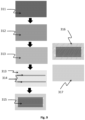
- FIG. 7 shows a coating methodology according to one embodiment of the invention for coating a non-conductive glass panel.
- FIG. 8 shows a coating methodology according to another embodiment of the invention for coating a non-conductive glass panel.
- FIG. 9 shows a coating methodology according to another embodiment of the invention for coating a conductive metal panel.
- FIG. 10 shows the thermal expansion characteristics of a glass frit glaze (Line 2; Ferro® SGF WHITE INT 19 4011 AL-6476 per Table 9) and a coating of the invention (Line 1; per Example 1A) as measured on a Netzch DIL 402 dilatometer (25-400° C., ramp rate 5.0° C./min, air atmosphere, sample lengths ⁇ 23 mm).
- the data show that the glass frit has a CTE of about 9.8 ppm/K between 25 and 400° C., and that a composite of the same glass frit and graphite has a lower CTE of about 8.7 ppm/K between 25 and 400° C.
- coating of the invention and related terms such as “glass coating”, “electrothermic layer” and “electrothermic glass layer” as used herein will be understood to refer to a glass layer produced by firing a glass frit having one or more carbon components dispersed therein.
- a glass coating of the invention may comprise on a solids basis: 1-65 wt % of a carbon component and 35-99 wt % of a glass frit.
- the carbon component may be a single graphite component or a mixture of two or more graphite components, a mixture of a graphite and carbon black component, a single carbon black component, or a mixture of two or more carbon black components.
- glass coating is applied to a substrate as a frit/carbon mixture (optionally with other components such as solvents, viscosity modifiers, vehicles, etc.) and is fired to produce the glass coating.
- glass frit refers to the pre-fired glass matrix
- glass coating refers to a fused or fired glass coating, i.e., the post-fired product comprising a carbon component.
- glass coating composition refers to the mixture of glass frit and carbon component (and optionally other components such as viscosity modifiers, etc) prior to firing.
- composite of the invention and related terms will be understood to refer to composite products comprising a substrate (which can itself comprise one or more layers) and a coating of the invention.
- Composites of the invention may optionally also include one or more overcoat layer(s) and/or plate(s).
- glass frit and related terms such as “frit” used herein refer to preparations containing a powdered or finely ground glass.
- a glass frit is usually a paste containing glass powder, organic binder, inorganic fillers and solvent(s).
- Persons of skill in the art will understand that alternative terms such as glass paste, glass ink, glass powder, glass glaze, vitreous enamel, vitreous glaze, glossy glaze, enamel glass frit, and the like may also be used to describe glass frits or coatings produced from glass frits.
- carbon component refers to graphite(s) or carbon black(s), or mixture(s) of the two.
- laminate and related terms “delaminate”, etc as used herein refer to a characteristic whereby layers of a composite—in this case, an electrothermic glass coating on a substrate—separate or fracture partially or fully at or in the plane where the layers meet.
- the term “maintaining structural integrity” as used herein refers to the coating of the invention retaining functionality as an electrothermic coating (be that by maintaining electrical conductivity and/or thermal conductivity and/or heat capacity and/or by maintaining its macroscopic appearance) and being free from macroscopic signs of mechanical deformity such as peeling, cracking, and crumbling. In some instances, such as when the performance of the electrothermic coating is negatively affected, the term may additionally refer to the coating being free from microscopic deformities, such as microscopic cracks.
- the present invention provides a composite material comprising an electrothermic glass coating on a substrate wherein the electrothermic layer comprises glass having a carbon component dispersed throughout, wherein the glass, the carbon component, and their relative concentrations are selected such that the electrothermic layer resists delamination from the substrate over repeated electrical heating and cooling cycles.
- the coating and substrate may have substantially equivalent coefficients of thermal expansion (CTEs).
- the coating may have a TCR of zero.
- the present invention is a significant advance over the prior art, in that the glass coating is electrothermic and remains bonded to a substrate during service (repeated electrical heating and cooling cycles) and does not delaminate.
- This combination of properties has not been suggested in the prior art or delivered by prior art solutions.
- a further significant advantage is that the glass composite itself acts as a heating element, and no separate induction apparatus is required, or no separate electrical heating element is required to generate heat. This represents a significant cost saving and therefore a significant advance over commercially-available cooktop devices. Additionally, a further advantage is that the glass coating is aesthetically pleasing. Additionally, a further advantage of the coating of the invention is that the possibility of electrocution by contact with the glass coating is reduced or eliminated entirely, and therefore the composite of the invention is safe.
- the present invention relates to a carbon component being blended with vitreous enamel materials or glass frits to form pastes which then are applied to (e.g. coated onto) substrates and fired to form a non-metallic electrical element in the form of an electrothermic glass coating.
- the present invention further provides a means by which to allow glass coatings to be applied indirectly to positive thermal expansion materials such as metals so as to reduce the likelihood of delamination of the glass coating, and in some embodiments, prevent delamination of the glass coating during service (repeated electrical heating and cooling cycles).
- the invention is formulated such that the carbon component does not burn out of the glass layer.
- the glass coatings of the invention are electrically conductive and exhibit electrothermic properties when activated. Activation may be by way of applying alternating current (AC) or direct current (DC) either directly to the coating or through electrodes in electrical communication with the coating. Activation may also be by way of microwave radiation (e.g., 900 MHz-2.4 GHz) of the coatings, or by way of induction heating of the coatings (e.g., though use of induction coils, solenoids, magnets, or the like).
- AC alternating current
- DC direct current
- Activation may also be by way of microwave radiation (e.g., 900 MHz-2.4 GHz) of the coatings, or by way of induction heating of the coatings (e.g., though use of induction coils, solenoids, magnets, or the like).
- the carbon component in the glass coating described herein may be a graphite, or it may comprise a mixture of two different graphites, or a mixture of a carbon black and a graphite, or a mixture of two different carbon blacks, as described further below.
- the carbon component may be a mixture of one carbon black and one graphite.
- the carbon component may be a mixture of one carbon black and two or more different graphites.
- the carbon component may be a mixture of two or more different carbon blacks and one graphite.
- the carbon component may be a mixture of two or more different carbon blacks and two or more different graphites.
- the carbon component may comprise or consist of one, or two or more different, graphites, optionally in combination with one, or two or more different, carbon blacks, or may comprise or consist of two or more different carbon blacks.
- the nature of the carbon component and quantity thereof in the coating affects the properties of the coating, in particular the thermal, chemical, and physical properties of the coating.
- one or more of the carbon component loading, carbon component surface area, and carbon component particle size may exert a significant effect on the glass coating.
- the inclusion of a carbon component in a glass frit may make the glass coating of the invention sufficiently compliant to accommodate mechanical stresses generated during use (heating and cooling cycles).
- the compliance may comprise greater strain properties to accommodate interfacial stresses between the glass coating and the substrate, such that the glass coating can surprisingly be bonded to a variety of different substrates having different thermal expansion characteristics without delaminating or cracking.
- the graphite-modified glass frit coating has a greater toughness than the unmodified glass frit.
- the inclusion of a carbon component in a glass frit appears to cause a chemical reaction in the glass frit during firing such that functional groups in the glass frit are reduced at the interface between the glass coating and the substrate, resulting in the glass coating having a more metallic behaviour at the interface.
- the addition of a carbon component in the glass frit may provide improved covalent bonding to the substrate, or improved ionic bonding, or hydrogen bonding, depending on the substrate.
- the surface area of the carbon component generally determines the ease at which it can be incorporated into the glass frit prior to firing, with lower surface area carbon components being generally easier to incorporate into glass frits, including being easier to incorporate at higher loadings, than higher surface area carbon components.
- higher surface area carbon components tend to exhibit better conductivities than lower surface area carbon components, hence conductivity of the glass coating may be improved by increasing the loading of higher surface area carbon components.
- the addition of a carbon component in the glass frit may alter the thermal characteristics of the glass coating such that the thermal characteristics are similar to the substrate to which it is applied, and may have similar coefficients of expansion and contraction, and may affect any thermal hysteresis.
- the thermal, chemical, and physical properties of the coating can be “tuned” to suit the properties of the substrate to which it is applied.
- a sufficient concentration of carbon/graphite is included to achieve the percolation threshold in order to provide electrical conductivity through the glass coating, and which also surprisingly affects one or more of the characteristics mentioned above (thermal, chemical, and physical properties) which enables the glass coating to adhere to the substrate and simultaneously resist delamination over repeated electrical heating and cooling cycles.
- a principal of general application disclosed herein is the use of a sufficient quantity of carbon/graphite in a glass frit/glaze to obtain electrothermic properties and to simultaneously obtain bonding of the glass layer to a variety of substrates, and which resists delamination after repeated electrical heating and cooling cycles.
- the inventor contemplates that the carbon/graphite particles are substantially sealed or encapsulated by the glass frit melting around the particles during the melting phase of the curing cycle, which may prevent them from being oxidised during use, leading to a robust electrothermic coating.
- the graphite causes the frit to be more wettable on the substrate, contributing to an improved bond between the glass coating and the substrate relative to bonding of the frit alone.
- the carbon component comprises a mixture of two or more different graphites (optionally further in combination with one or more carbon blacks)
- the graphites may be present at any suitable ratio, for example, a first and second graphite may be present at a ratio of 1:100, 10:90, 20:80, 30:70, 40:60, 50:50, 60:40, 70:30, 80:20, 90:10 or 100:1.
- the carbon blacks may be present at any suitable ratio, for example, a first and second carbon black may be present at a ratio of 1:100, 10:90, 20:80, 30:70, 40:60, 50:50, 60:40, 70:30, 80:20, 90:10 or 100:1.
- the carbon black:graphite ratio may be between 10:1 and 1:10, or between 1:2 and 1:5, or between 1:4 and 1:8, or between 1:5 and 1:10, or between 2:1 and 5:1, or between 4:1 and 8:1, or between 5:1 and 10:1, or 10:1, 9:1, 8:1, 7:1, 6:1, 5:1, 4:1, 3:1, 2:1, 1:1, 1:2, 1:3, 1:4, 1:5, 1:6, 1:7, 1:8, 1:9 or 1:10.
- the carbon black:graphite ratio in the glass coating may be between about 1:5 to 1:7, e.g., 1:6.
- the total amount of the carbon component incorporated in the glass frit is between 1 and 65 wt %, and preferably between 4 and 55 wt %.
- the total amount of carbon component may be between 2 and 45, or between 3 and 45, or between 5 and 10, or between 10 and 15, or between 15 and 20, or between 20 and 25, or between 15 and 30, or between 10 and 20, or between 20 and 30, or between 25 and 35, or between 25 and 40, or between 30 and 45, or between 4 and 30, or between 20 and 50, or between 30 and 60 wt %, e.g., at a concentration of about 1, 2, 3, 4, 5, 6, 7, 8, 9, 10, 11, 12, 13, 14, 15, 16, 17, 18, 19, 20, 21, 22, 23, 24, 25, 26, 27, 28, 29, 30, 31, 32, 33, 34, 35, 36, 37, 38, 39, 40, 41, 42, 43, 44, 45, 50, 55, 60, or 65 wt %.
- the total carbon component may be the amount of graphite (where the only carbon component is one or more graphites).
- the total carbon component may be the amount of carbon black (where the only carbon component is one or more carbon blacks).
- the total carbon component may be the amount of carbon black and graphite (where the carbon component is one or more carbon blacks and one or more graphites). Carbon component concentrations of below 1% generally do not provide adequate conductivity to the coatings of the invention.
- the nature and concentration of the graphite component influences the current loading of the glass coating of the invention, as well as influencing the CTE of the resultant glass coating.
- the graphite component may be utilised to produce a glass frit-graphite composite having a lower CTE than the glass frit alone (without graphite), such that the CTE of the glass coating containing graphite is closer in value to the CTE of a substrate, e.g., low thermal expansion glass.
- a substrate e.g., low thermal expansion glass.
- the graphite may also act to chemically reduce the frit in part (e.g., by removing oxygen from the siloxane groups during firing) such that the frit exhibits greater wettability at the interface with the substrate.
- Graphite in the glass coating of the invention may have an average particle size in the range of between about 10 nm to 350 ⁇ m, e.g., of 10 nm to 1 ⁇ m, or of 1 ⁇ m to 65 ⁇ m, or of 100 nm to 10 ⁇ m.
- nanographites having an average particle size of between about 10 nm and 1000 nm may be used, e.g., nanographites having an average particle size of between 10 nm and 100 nm, or between 50 nm and 250 nm, or between 200 and 500 nm, or between 500 and 1000 nm, or between 400 and 750 nm, e.g., of 10 nm, 50 nm, 100 nm, 500 nm or 1000 nm may be used.
- Graphites having an average particle size in the range of between about 1 ⁇ m to 350 ⁇ m may also be used, e.g., graphites having an average particle size of from 1 ⁇ m to 45 ⁇ m, or from 40 ⁇ m to 60 ⁇ m, or from 20 ⁇ m to 40 ⁇ m, or from 30 ⁇ m to 50 ⁇ m, or from 40 ⁇ m to 50 ⁇ m, or from 40 ⁇ m to 60 ⁇ m, or from 50 ⁇ m to 100 ⁇ m, or from 100 ⁇ m to 250 ⁇ m, or from 200 ⁇ m to 350 ⁇ m, or of less than 300, of less than 200, of less than 100, of less than 65, less than 60, less than 55, less than 50, less than 45, less than 40, less than 35, less than 30, less than 25, less than 20, less than 15, less than 10 or less than 5 ⁇ m, or of 350, 300, 250, 200, 150, 100, 85, 65, 60, 55, 50, 45, 40, 35, 30, 25, 20, 15, 10, 5, 4,
- Graphite in the glass coating of the invention may have a surface area of between from about 1 to about 400 m 2 /g.
- the graphite may be a low surface area graphite having a surface area of between 1 and 5, or between 1 and 10, or between 5 and 20, or between 20 and 30, or between 15 and 25, or between 1 and 30 m 2 /g, e.g., 1, 2, 3, 4, 5, 10, 12.5, 15, 17.5, 20, 22.5, 25, 27.5 or 30 m 2 /g.
- the graphite may be a higher surface area graphite having a surface area of between 50 and 400 m 2 /g, e.g., between 100 and 150, or between 100 and 200, or between 50 and 200, or between 150 and 250, or between 200 and 375, or between 250 and 350, or between 300 and 400, or between 100 and 400 m 2 /g, e.g., 50, 100, 120, 140, 160, 180, 200, 220, 240, 260, 280, 300, 320, 340, 360, 380, or 400 m 2 /g.
- graphites having surface areas of greater than 400 m 2 /g may be used provided sufficient shear is used to incorporate the graphite into the glass frit during manufacture of the glass coating.
- the graphite has a surface area of less than 300 m 2 /g, or of less than 200 m 2 /g, or of less than 100 m 2 /g.
- Graphites having a surface area of less than about 300 m 2 /g are advantageously able to incorporate into glass frits under mild shear conditions.
- the surface area may be a N 2 (NSA) BET surface area.
- Nitrogen adsorption measurements at liquid nitrogen temperature may be used to characterise the total surface area of graphites (and carbon blacks) herein based on the Brunauer, Emmett, and Teller (BET) theory of multilayer gas adsorption (see also ASTM method D 6556-04).
- BET Brunauer, Emmett, and Teller
- the graphite particles are preferably heat treated prior to incorporation in the glass coatings and glass coating compositions of the invention, and preferred minimum temperatures for heat treatment are at least 3500° C., at least 3000° C., at least 2500° C., at least 2000° C., at least 1500° C., at least 1400° C., at least 1300° C., at least 1200° C., at least 1100° C., or at least 1000° C.
- the graphite particles may be heat treated to a temperature of between 1000 and 1500° C., or between 1200 and about 3500° C., or between 1500 and 2000° C., or between 2000 and 3500° C., or between 1000 and 3000° C.
- Graphite particles produced by such heat treatment processes generally have a relatively higher surface area than equivalent non-heat treated graphites. They may advantageously withstand the high temperatures employed in firing glass frits to produce glass coatings of the invention without evaporating.
- heat treated graphites are highly conductive, so a relatively lower amount is required in the composition (compared to equivalent non-heat treated graphites) which may be advantageous when formulating the glass coatings of the invention.
- the graphites used herein preferably have a crystallinity of between 60% to 99%.
- graphites having crystallinities of between 60 and 80%, or between 75 and 90%, or between 85 and 99%, or between 90 and 99%, or between 95 and 99% are preferred, e.g., crystallinities of at least 60%, at least 70%, at least 80%, at least 85%, at least 90%, at least 95% or at least 99%, e.g., crystallinities of 60%, 70%, 80%, 85%, 90%, 95% or 99%.
- Graphite particles in the glass coating preferably have a resistivity of about less than about 1.0 ⁇ cm, less than about 0.8 ⁇ cm, less than about 0.5 ⁇ cm, less than about 0.1 ⁇ cm, or less than about 0.05 ⁇ cm, e.g., a resistivity of between 0.01 and 0.05, or between 0.05 and 0.10, or between 0.05 and 0.15, or between 0.10 and 0.20, or between 0.15 and 0.25, or between 0.25 and 0.4, or between 0.20 and 0.50, or between about 0.4 and 0.65, or between 0.50 and 0.75, or between 0.75 and 1.0, or of between 0.01 and 1 ⁇ cm.
- the graphite may have a resistivity of 0.01, 0.02, 0.03, 0.04, 0.05, 0.06, 0.07, 0.08, 0.09, 0.1, 0.2, 0.3, 0.4, 0.5, 0.6, 0.7, 0.8, 0.9 or 1.0 ⁇ cm.
- the graphite component may be present in the pre-fired glass coating composition of the invention in a solids concentration of between 4 and 10%, or between 10 and 15%, or between 15 and 20%, or between 20 and 25%, or between 15 and 25%, or between 10 and 20%, or between 20 and 50%, or between 25 and 45%, or between 30 and 50%, or between 15 and 45%, or between 40 and 65%, e.g., at a concentration of about 1, 5, 6, 7, 8, 9, 10, 11, 12, 13, 14, 15, 16, 17, 18, 19, 20, 21, 22, 23, 24, 25, 28, 30, 32, 34, 36, 38, 40, 42, 44, 45, 46, 48, 50, 55, 60 or 65 wt %.
- the graphite may be present in the glass coating composition of the invention in a concentration (calculated as weight parts in the pre-fired composition) of 30-50 parts glass frit (in paste form) to 3-15 parts graphite, or of 35-45 parts glass frit (in paste form) to 5-10 parts graphite, or of 38-42 parts glass frit (in paste form) to 5.5-8 parts graphite.
- concentration calculated as weight parts in the pre-fired composition
- there are 40 parts glass frit (in paste form) and 6 parts graphite in the pre-fired glass coating there are 40 parts glass frit (in paste form) and 6 parts graphite in the pre-fired glass coating.
- the glass frit (in paste form) is 76%-79% powder (solids) and 24%-21% medium, and accordingly, the aforementioned ratios may be proportionally adjusted to calculate corresponding glass frit mass ratios for glass frits having higher or lower solids loadings.
- the graphite may be any suitable graphite.
- the graphite may be natural graphite, synthetic graphite, amorphous graphite, calcined petroleum coke, crystalline flake graphite, natural flake graphite, surface enhanced flake graphite, expandable graphite, purified flake graphite, purified crystalline flake graphite, purified petroleum coke, purified synthetic graphite, purified-vein graphite, synthetic graphite, primary artificial graphite, secondary artificial graphite, spherical natural graphite, or vein graphite, or a mixture of any two or more of these.
- the graphite may be primary synthetic graphite or natural graphite.
- the graphite may have any suitable morphology.
- the graphite particles may have a shape such as flake-like, spherical-like, needle-like, plate-like, wire-like, tube-like, whisker-like, ball-like, nano graphites, tubes, wires, or a combination of any two or more of these.
- the shape of graphite particles used herein is preferably flake-like, plate-like, needle-like or wire-like, or tube-like.
- the graphite used in the glass coating of the invention has an average particle size of between 1-40 ⁇ m, a carbon content of greater than 97%, a surface area of between 1 and 300 m 2 /g and is of a grade selected from: secondary artificial, primary artificial, natural amorphous, and natural crystalline flake, or a combination of two or more of these grades.
- a high surface area graphite is selected, e.g., graphite with a surface area of 100-400 m 2 /g, where the mean particle size is less than about 4 microns, and the corresponding resistivity is between about 0.05 and 0.7 ⁇ cm.
- a greater percentage of graphite is required by mass in the glass coating to achieve adequate conductivity.
- more than one layer of glass coating may be required to be applied on the same substrate.
- a lower surface area graphite may be used, e.g., graphite with a surface area of about 1 to 30 m 2 /g, where the mean particle size is between about 5 and 45 microns, and the corresponding resistivity is between about 0.01 and 0.15 ⁇ cm.
- a lower percentage of graphite is required by mass in the glass coating to achieve adequate conductivity.
- only one layer of the glass coating may be required to be applied on the chosen substrate.
- the graphite in the glass coating may be a single type of graphite having characteristics as described in this section, or may be a mixture of two or more graphites having different characteristics as described in this section, such as different surface area, and/or different average particle size, and/or different morphology, etc.
- a mixture of high and low surface area graphite and/or small and large particle size graphite and/or high or low resistivity graphite and/or graphites having different particle morphologies may be combined in a single glass coating.
- the ratio of different graphite products may be used to tune the final properties of the glass coating, for example, the final conductivity and/or the final CTE.
- the first graphite may have a surface area that is between 1 and 100 times greater than the surface area of the second graphite, e.g., between 1 and 20, or 20 and 40, or 25 and 75, or 50 and 80, or 75 and 100 times greater.
- the first graphite may have an average particle size that is about 1 to 50 times smaller than the average particle size of the second graphite, e.g., between 1 and 10, or 5 and 25, or 10 and 30, or 20 and 40, or 35 and 50 times smaller.
- Graphites from ThermoPURETM suitable for the present invention include 1500 Series powder; 2500 Series powder; 2900 Series Crystalline Flake Graphite Oxidation Resistant; 3000 Series powder; 4200 Series powder; 4500 Series powder; 4700 Series powder; 4900 Series powder; 5000 Series powder; 5200 Series powder; 5500 Synthetic Graphite High Purity; 6500 Series powder; 7800 Series powder; 8000 Series powder and 9000 Series powder.
- Resilient Graphitic CarbonsTM such as PureBlackTM, FormulaBTTM or Desulco grades may be used in the invention.
- Other suitable graphites may be sourced from TIMREX® Graphite Dispersions. These graphite dispersions are water based (solvent-free). Natural and synthetic graphite materials by the manufacturer Asbury are particularly suitable for the invention. The grades in Table 2 are suitable:
- SEFG surface enhanced flake graphites
- SEFG surface enhanced flake graphites
- the grades in the following Table 4 are suitable for the present invention and are a unique form of primary synthetic graphite manufactured by a special treatment of the highest quality calcined needle coke.
- the graphite is made using a process which subjects the precursor carbon to temperatures above 2500° C.
- the resultant graphite is a single phase (no graphitized binder phase), open pore graphite that is high in purity, lubricious, and has excellent thermal and electrical conductivity.
- a surface enhanced flake graphite sold as product 5773 by Intelliparticle® and having the following properties is particularly suitable:
- the carbon component in the coating of the invention e.g., the graphite
- CTE coefficient of thermal expansion
- the carbon component e.g., graphite
- the carbon component may have a CTE that is within about 4 ppm/K, or within about 3 ppm/K, or within about 2 ppm/K, or within about 1 ppm/K, or within about 0.5 ppm/K of the CTE of the glass frit into which it is dispersed between 50 and 400° C., or between 50 and 100° C., or between 150 and 350° C.
- the carbon component, e.g., graphite is incorporated into the glass frit in such a manner as to be equiaxed.
- the graphite used in the glass coatings of the invention have a coefficient of thermal expansion (CTE) between 50 and 400° C. that is between about 4 ppm/K and about 8 ppm/K, e.g., between 5 ppm/K and 7 ppm/K, e.g., graphite, may have a CTE that is 4 ppm/K, or 5 ppm/K, or 6 ppm/K, or 7 ppm/K, or 8 ppm/K between 50 and 400° C., or between 50 and 100° C., or between 25 and 350° C., or between 150 and 350° C., or between 20 and 750° C.
- CTE coefficient of thermal expansion
- the skilled person will understand the concept of percolation threshold.
- the present invention utilises a minimum of a percolation-threshold concentration of graphite (or carbon, or mixture of carbon and graphite) to obtain sufficient electrical conductivity to produce an electrothermic coating—so-called “electrical percolation”.
- the coatings of the present disclosure simultaneously display bonding with a variety of substrates and resist delamination over repeated electrical heating and cooling cycles.
- Glass coatings of the invention may comprise a single carbon black, or one or more carbon blacks in combination with one or more graphites, or may comprise two or more carbon blacks.
- the use of smaller particle size carbon blacks mixed with relatively larger particle sizes of graphite or carbon black may produce improved heat production from the glass coating of the invention.
- Inclusion of two different carbon blacks having different particle sizes and/or surface areas in a glass coating of the invention also allows the thermal coefficient of resistance (TCR) of the glass coating to be modified, e.g., to about zero, and particularly at higher temperatures of over 350° C. Further, without wishing to be bound by any theory, it is believed that inclusion of carbon black particles may counteract the negative thermal coefficient of resistance of graphite, so that the resulting formulation can be formulated to have a TCR of zero.
- Carbon black is an intense black powder made by incomplete combustion or thermal cracking of a hydrocarbon feedstock. Carbon blacks are classified as furnace blacks (produced by burning oil in 50% air), thermal blacks (produced through thermal decomposition of methane) and channel blacks (produced by direct combustion of fossil fuels or municipal waste). The majority of carbon blacks are produced using furnace processes.
- Carbon black is composed of nanometer-sized primary particles which can bond together to form primary aggregates of various shapes and structures.
- the primary aggregates can cluster into larger agglomerates, forming fluffy, free-flowing powders, or they may be bonded into beads.
- a high structure carbon black is one in which the aggregates are composed of many prime particles clustered together with considerable branching and chaining. As a result, the aggregates pack more poorly reducing the inter-aggregate attractive forces. Low structure carbon blacks are more compact, allowing closer packing and thus greater inter-aggregate attractive forces which makes dispersion more difficult.
- the structure of carbon black is measured through an oil absorption process, called dibutylphthalate absorption (DBPA or DBP).
- DBPA dibutylphthalate absorption
- the particle size (fineness) of carbon blacks is generally inversely related to their surface area. Small particle size (or high surface area) carbon blacks have increased blackness, tint, UV protection, and electrical conductivity, but reduced dispersability.
- Carbon blacks in the glass coating of the invention may have an average particle size in the range of between about 1 nm to 1000 nm, e.g., between about 1 nm and 100 nm, or between 1 nm and 200 nm.
- the carbon blacks may have an average particle size of from 1 nm to 45 nm, 1 nm to 30 nm, or from 10 nm to 30 nm, or from 40 nm to 60 nm, or from 20 nm to 40 nm, or from 30 nm to 50 nm, or from 40 nm to 50 nm, or from 40 nm to 60 nm, or from 1 nm to 100 nm, or from 100 nm to 150 nm, or from 150 nm to 200 nm, or from 200 to 500 nm, or from 200 to 750 nm, or from 500 to 800 nm, or from 750 to 1000 nm, or of less than 750, of less than 500,
- Carbon blacks in the glass coating of the invention may have a surface area of between about 5 to about 1500 m 2 /g, preferably of between about 5 and 300 m 2 /g, or between 5 and 700 m 2 /g.
- the carbon blacks may be low surface area carbon blacks having a surface area of between 5 and 300, or between 5 and 100, or between 10 and 250, or between 100 and 300, 150 and 200, or between 175 and 250, or between 200 and 275, or between 100 and 200, or between 250 and 300 m 2 /g, e.g., of less than 300, or less than 250, or less than 200, or less than 100 m 2 /g, e.g., of 5, 10, 20, 40, 50, 60, 80, 100, 125, 150, 175, 200, 225, 250, 275, or 300 m 2 /g.
- the carbon blacks may be higher surface area carbon blacks having a surface area of between 800 and 1500, or between 800 and 900, or between 850 and 1050, or between 900 and 1100, or between 950 and 1250, or between 1000 and 1500, or between 1100 and 1300 m 2 /g, e.g., 800, 850, 900, 950, 1000, 1050, 1100, 1150, 1200, 1250, 1300, 1350, 1400, 1450 or 1500 m 2 /g.
- high surface are carbon blacks may be used provided sufficient shear is used to incorporate the carbon blacks into the glass frit during manufacture of the glass coating.
- the carbon blacks have a surface area of less than 300 m 2 /g, or of less than 200 m 2 /g, or of less than 100 m 2 /g.
- Carbon blacks having a surface area of less than about 300 m 2 /g are advantageously able to incorporate into glass frits under mild shear conditions.
- the surface area may be a N 2 BET (NSA) surface area.
- Carbon blacks in the glass coating of the invention may have an oil absorption (OAN) of between about 250 and 600 mL/100 g.
- OAN oil absorption
- the carbon blacks may have an OAN of between 250 and 300, between 275 and 350, between 350 and 450, between 380 and 460, between 400 and 460, between 450 and 525, or between 500 and 600 mL/100 g, e.g., of 250, 275, 300, 325, 350, 375, 400, 425, 450, 475, 500, 525, 550, 575 or 600 mL/100 g.
- Carbon blacks in the glass coating of the invention may have any suitable pH.
- the carbon black may have a pH of between about 5 and about 10, for example, between 5 and 8, or between 7 and 9, or between 6 and 9, or between 6 and 10, e.g., a pH of 5, 5.5, 6, 6.5, 7, 7.5, 8, 8.5, or 9.
- the carbon blacks may have an iodine absorption number (in g/kg) of between about 1000 and 1300, or between about 1025 and 1225, or between about 1050 and 1150, or between about 1150 and 1250, e.g., of 1000, 1050, 1100, 1125, 1150, 1200, 1250, or 1300 g/kg.
- the carbon black particles may comprise particle aggregates of a size range characterised by having a dibutyl phthalate (DPB) absorption in the range of between about 45 to 500 ml/100 g, or between 300 and 500, or between 350 and 450, or between 75 and 220, or between 200 and 350 ml/100 g (as determined by ASTM D1510—12 Standard).
- DPB dibutyl phthalate
- the carbon black component may be present in the pre-fired glass coating composition of the invention in a solids concentration of between 1 and 10%, or between 1 and 3%, or between 2 and 4%, or between 3 and 5%, or between 5 and 7%, or between 6 and 8%, or between 10 and 25%, or between 15 and 30%, or between 1 and 20%, or between 20 and 45%, or between 1 and 45%, or between 40 and 65%, or between 4 and 25%, or between 30 and 50%, e.g., at a concentration of about 1, 1.5, 2, 2.5, 3, 3.5, 4, 4.5, 5, 5.5, 6, 6.5, 7, 7.5, 8, 10, 15, 20, 25, 30, 35, 40, 45, 50, 55, 60 or 65%.
- the carbon black may be present in the glass coating composition of the invention in a concentration (calculated as weight parts in the pre-fired composition) of 30-50 parts glass frit (in paste form) to 3-15 parts first carbon black to 0.1 to 8 parts second carbon black, or of 35-45 parts glass frit (in paste form) to 5-10 parts first carbon black to 1 to 5 parts second carbon black, or of 38-42 parts glass frit (in paste form) to 5-7 parts first carbon black to 1.5 to 3 parts second carbon black. In one embodiment, there are 40 parts glass frit (in paste form), 6 parts first carbon black and 1 part second carbon black in the pre-fired glass coating.
- the carbon black may be present in the glass coating composition of the invention in a concentration (calculated as weight parts in the pre-fired composition) of 30-50 parts glass frit (in paste form) to 3-15 parts graphite to 0.1 to 8 parts carbon black, or of 35-45 parts glass frit (in paste form) to 5-10 parts graphite to 1 to 5 parts carbon black, or of 38-42 parts glass frit (in paste form) to 5-7 parts graphite to 1.5 to 3 parts carbon black. In one embodiment, there are 40 parts glass frit (in paste form), 6 parts graphite and 1 part carbon black in the pre-fired glass coating.
- the glass frit (in paste form) is 76% powder (solids) and 24% medium, and accordingly, the aforementioned ratios may be proportionally adjusted to calculate corresponding glass frit mass ratios for glass frits having higher or lower solids loadings.
- the carbon black may be any from any suitable source, for example, may be a conventional thermal black, furnace black, lamp black, channel black, highly purified carbon, surface-modified carbon black, surface functionalised carbon blacks heat-treated carbon, nano carbon or a combination of two or more of these.
- Particularly preferred carbons for use with the invention are furnace blacks, lamp blacks, channel blacks, surface modified carbons, and heat-treated carbons.
- acetylene blacks are not suitable for use in the invention, as they produce a fume when brought up to temperatures past 150° C.
- Acetylene blacks are produced from acetylene gas and are not heat treated, and their chemical makeup and structure makes them different from furnace and channel blacks, which are suitable for use in the invention.
- the invention includes the proviso that carbon blacks generated by high temperature pyrolysis of acetylene (such as Ketjenblacks) are not used.
- the carbon black particles in the glass coating may have any suitable morphology.
- they may be flake-like, spherical-like, needle-like, plate-like, wire-like, tube-like, whisker-like, ball-like, single-wall, double-wall, multi-wall carbon nano tubes, buckyballs, quantum dots, or a combination of any two or more of these.
- the carbon blacks are flake-like, spherical-like, needle-like, plate-like, wire-like, tube-like, whisker-like, or ball-like.
- the carbon black used in the glass coating of the invention has an average particle size of between 10-40 nm and a surface area of between 800 and 1200 m 2 /g.
- the carbon blacks present in the glass coating with one or more graphites may have a surface area that is between 1 and 100 times greater than the surface area of the graphite, e.g., between 1 and 20, or 20 and 40, or 25 and 75, or 50 and 80, or 75 and 100 times greater.
- the carbon black may have an average particle size that is about 1 to 1000 times smaller than the average particle size of the graphite, e.g., between 1 and 100, or 50 and 250, or 300 and 500, or 400 and 650, or 600 and 800 times smaller.
- the carbon black in the glass coating may be a single type of carbon black having characteristics as described in this section, or may be a mixture of two or more carbon blacks having different characteristics as described in this section, such as different surface area, and/or different average particle size, and/or different morphology, etc.
- a mixture of high and low surface area carbon black and/or small and large particle size carbon black and/or carbon blacks having different particle morphologies may be combined in a single glass coating.
- the ratio of different carbon black products may be used to tune the final properties of the glass coating, for example, the final conductivity and/or the final CTE.
- the first carbon black may have an average particle size that is about 1 to 1000 times smaller than the average particle size of the second carbon black, e.g., between 1 and 100, or 50 and 250, or 300 and 500, or 400 and 650, or 600 and 800 times smaller.
- Carbon blacks having certain polar surface functionalities may be used.
- the skilled person will understand the concept of percolation threshold.
- the present invention utilises a minimum of a percolation-threshold concentration of conductive carbons to obtain sufficient electrical conductivity to produce an electrothermic coating—so-called “electrical percolation”.
- the coatings of the present disclosure simultaneously display bonding with a variety of substrates and resist delamination over repeated electrical heating and cooling cycles.
- the glass coating composition of the present invention comprises an enamel glass frit.
- a carbon component is combined with the glass frit, and this mixture is optionally further modified by mixing with viscosity modifying oils before being applied to a substrate and subsequently fired/melted to form a glass coating according to the present invention.
- the present inventor believes that the glass frits described herein are particularly suitable for producing glass coatings of the invention as they may provide good wetting of the surface of a variety of substrates, and in particular, of low thermal expansion/high temperature glasses such as Ceran® or Extrema® glass.
- the glass frits may comprise a glass powder such as silicate, borosilicate, non-alkaline earth borosilicate, alkaline earth-containing borosilicate, high borate borosilicate, transition metal borosilicate, alkaline earth aluminosilicate, alkali aluminosilicate, alkaline-free aluminoborosilicate, alkali-lead silicate, soda lime glass (alkali alkaline earth silicate), lithium-aluminium-silicate glass ceramic, or the like, etc.
- a glass powder such as silicate, borosilicate, non-alkaline earth borosilicate, alkaline earth-containing borosilicate, high borate borosilicate, transition metal borosilicate, alkaline earth aluminosilicate, alkali aluminosilicate, alkaline-free aluminoborosilicate, alkali-lead silicate, soda lime glass (
- the frit herein is selected from the group consisting of: silicate, borosilicate, and transition metal borosilicate. In other embodiments, the frit herein is selected from the group consisting of: silicate, borosilicate, and zinc borosilicate.
- Common oxides used to form glasses ground into glass frits include network formers such as B 2 O 3 , SiO 2 , P 2 O 5 , intermediates such as Al 2 O 3 , ZrO 2 , and TiO 2 and network modifiers SnO, MgO, ZnO, Li 2 O, CaO, SrO, BaO, Na 2 O, K 2 O.
- the frit may comprise a glass powder having a minimum of 40%, 50%, 60%, 70% or 80% SiO 2 .
- the frit may be a borax frit, lead bisilicate frit or lead borosilicate frit. Zinc borosilicate glass frits are particularly preferred.
- the glass component may include one or more oxides selected from the group consisting of P 2 O 5 , Al 2 O 3 , ZrO 2 , SiO 2 , Na 2 O, K 2 O, BaO, TiO 2 , ZnO, Co 2 O 3 , NiO, Cr 2 O 3 , MnO 2 , CuO, and combinations thereof.
- the glass component may also include one or more additional components such as but not limited to Li 2 O, Rb 2 O, Cs 2 O, MgO, CaO, SrO, ZnO, CeO 2 , LaO 2 , B 2 O 3 , FeO, Fe 2 O 3 , and Fe 3 O 4 .
- the glass component of the coatings preferably comprises a combination of one or more alkali oxides represented as R 2 O, one or more alkaline earth oxides represented as RO, and one or more various transition metal oxides represented herein as MO, MO 2 , and M 2 O 3 .
- R 2 O represents alkali oxides, preferably selected from the group consisting of Li 2 O, Na 2 O, and K 2 O.
- the formula RO represents alkaline earth oxides, preferably selected from the group consisting of MgO, CaO, SrO, and BaO.
- MO includes ZnO, NiO, and CuO for example.
- MO 2 includes TiO 2 and ZrO 2 for example.
- M 2 O 3 includes Co 2 O 3 and Cr 2 O 3 for example. It will be understood that M can be any transition metal.
- Frits suitable for use in the present invention may comprise inorganic fillers such as opacifiers or pigments.
- opacifiers are zircon, tin oxide or titania.
- Typical pigments include calcined stains such as zircon vanadium blue, zircon iron coral or the zircon praseodymium yellow, and oxides such as iron (Fe 2 O 3 ) cobalt (CoO), chrome (Cr 2 O 3 ), and manganese (MnO 2 ).
- the glass frits may include an effective amount of one or more additives such as fluorine and/or NO 2 .
- the additives may be present in the glass frit at a concentration of between 1-15%.
- Other additional components that may be present in the glass frit and/or coating are described below in the section entitled “Other components”.
- frits suitable for use in the present invention may comprise suspending agents, flocculants, deflocculants, binders, bactericides, organic dyes, wetting agents, and antifoam agents, dispersants, surfactants, clay materials or formers such as kaolinite clays, silica, talc, silicas, and inert extenders such as, for example, titanium dioxide, zinc oxide, other metal oxides, colourants, opacifiers, inhibiting pigments, plasticizers, pigment suspending agents, flow levelling agents, catalysts, drying agents, surfactants, tinctorial pigments, or a wide variety of other conventional additives.
- the frit used herein comprises titanium dioxide as a pigment.
- the frit used herein is devoid of pigment and hence produces a clear glass.
- the glass frit used in the present invention preferably has a firing temperature of between about 600 and 750° C. in air, e.g., between 600 and 650° C., or between 625 and 675° C., or between 650 and 750° C., or between 700 and 750° C., e.g., 600, 625, 650, 675, 700, 725 or 750° C. in air.
- the glass frit used in the present invention may have a firing temperature of between about 100 to 2500° C.
- inert gases such as nitrogen or argon (or a mixture of inert gases), e.g., between 100 and 500° C., or between 300 and 800° C., or between 500 and 1500° C., or between 1000 and 2000° C., or between 1500 and 2500° C., e.g., 100, 200, 300, 400, 500, 600, 700, 800, 900, 1000, 1250, 1500, 1750, 2000, 2250 or 2500° C. in a reduced atmosphere kiln with injection of one or more inert gases such as nitrogen or argon (or a mixture of inert gases).
- the gas or mixture of gases
- the gas may be introduced when the kiln is at between 650 and 1500° C.
- the glass frit used in the present invention preferably has a drying temperature of between about 120 and 150° C. in air, e.g., of between 120 and 130° C., or between 125 and 135° C., or between 130 and 145° C., or between 135 and 150° C., or of 120, 125, 130, 135, 140, 145 or 150° C. in air.
- the drying process drives off volatile solvent carrier(s) used to form the glass frit into a paste suitable for application and is performed prior to firing the glass frit.
- the annealing point of the glass frit may be between 300 and 1450° C., or between 300 and 1150° C., e.g., of greater than about 500° C., of greater than about 600° C., of greater than about 700° C., e.g., greater than 750° C., greater than 800° C., greater than 850° C., greater than 900° C., greater than 950° C., greater than 1000° C., greater than 1050° C., greater than 1100° C., or greater than 1150° C., e.g.
- Frits having higher annealing points e.g., above 1150° C., may be suitable for inert atmosphere firing. Frits having lower annealing points, e.g., below 1150° C., may be suitable for air firing.
- the glass frit used in the glass coating of the invention preferably forms a glass having a CTE of between about 4 and 12 ppm/K after curing (without addition of a carbon component), e.g., a CTE of between 4 and 5, or 5 and 6, or 6 and 7, or 3 and 6, or 4 and 5, or 5 and 8, or 6 and 9, or 7 and 10, or 8 and 12, or 6 and 12, or 8 and 11, ppm/K e.g., a CTE of 4, 4.5, 5, 5.5, 6, 6.5, 7, 7.5, 8, 8.5, 9, 9.5, 10, 10.5, 11, 11.5 or 12 ppm/K.
- the CTE may be the CTE at a temperature of between 25 and 300° C., or between 25 and 125° C., or between 200 and 300° C., or between 50 and 400° C., or between 240 and 270° C., or at 260° C.
- the glass frit may be a mixture of two or more different, compatible glass frits.
- the glass frit may be a mixture of any two or more of the frits described herein.
- each glass frit has a different firing temperature.
- a frit having a firing temperature of 650° C. may be mixed with a frit having a firing temperature of 850° C.
- any suitable proportion e.g., between 1:10 and 10:1, e.g., from 1:10 to 1:1, or from 1:1 to 1:10, or between 60:40 and 10:90, or between 70:30 and 80:20, or between 75:25 and 85:15, e.g., about 60:40, 65:35, 70:30, 75:25, 80:20, or 85:15
- the glass frit may be provided in the form of a paste.
- the paste may have any suitable solids loading, but for example, may be between about 60:40 solids:medium and about 85:15 solids:medium, e.g., between 60:40 and 70:30, or between 70:30 and 80:20, or between 75:25 and 85:15, e.g., about 60:40, 65:35, 70:30, 75:25, 80:20, or 85:15, where the medium is any suitable medium.
- the medium may be an oil such as pine oil.
- the glass frit component may be present in the pre-fired glass coating composition of the invention in a solids concentration of between 70 and 75%, or between 75 and 80%, or between 80 and 85%, or between 85 and 90%, or between 75 and 85%, or between 80 and 90%, or between 35 and 50%, or between 70 and 90%, or between 75 and 96%, or between 65 and 90%, e.g., at a concentration of about 30, 35, 45, 50, 55, 60, 65, 67.5, 70, 72.5, 75, 77.5, 80, 82.5, 85, 87.5, 90, 92.5 or 95%.
- the glass frit may be mixed with one or more carbon components such that the glass frit (including carrier/medium) comprises between 15 and 75 wt % of the total mixture.
- the glass frit may be provided in the form of a paste having a solids loading of, for example, between about 60:40 solids:medium and about 85:15 solids:medium, in particular, 75:25 solids:medium.
- the glass frit paste component may be present in the pre-fired glass coating composition at between 15 and 30 wt %, or between 20 and 40%, or between 30 and 60%, or between 50 and 75%, or between 65 and 75%, or between 30 and 70%, e.g., at a concentration of about 15, 20, 25, 30, 35, 40, 45, 50, 55, 60, 65, 70 or 75%.
- Curing of the glass frits can be baking/firing at a temperature for a suitable period to effect curing, drying or melting of the frit as described in the following methods section. Curing/firing conditions are well known to persons skilled in the art of such materials. For example, suitable glazing and firing temperature profiles for the glass frits described in this section are presented in FIGS. 1 - 3 . These thermal profiles are particularly suitable for the glazes produced by Ferro, such as GSGF ETCH 19 4021 AL-6479 and GSGF WHITE INT 19 4011 AL-6476.
- the frits described in this section are all suitable for use with graphites and carbon blacks as described herein to make electrothermic coating compositions suitable for application to a range of substrates such as low thermal expansion glass and prepared metal substrates.
- the coatings have a CTE closely matched to the CTE of the substrate.
- the coatings formed from these frits are non-metallic conductive glass heating elements, and can be coated onto a variety of substrates, such as Ceran® glass, Nextrema® glass, and a variety of other glass substrates as discussed in the following section “Substrates”. As discussed herein, more than one carbon component can be utilised with the glass frits described in this section in the glass coating of the invention.
- the glass coating of the present invention may comprise one or more metals.
- the metal may be a Group I or Group II metal, or a transition metal.
- the metal may be copper, zinc, nickel, or silver.
- the metal may be present in elemental form.
- the metal may be present in oxide form, e.g., titanium dioxide.
- the metal may be in the form of metal particles.
- the metal may be present in the glass coating composition in any suitable amount, e.g., in an amount of from 1 to 20 wt % by weight of the glass coating composition on a solids basis, or below 10 wt %, or 9, 8, 7, 6, 5, 4, 3, 2, 0.5, 0.25, or 0.1 wt %.
- the metal particles are present in a concentration which is below that at which arcing can occur between the glass coating of the invention and an article brought into close proximity to, or touching, the surface of the glass coating of the invention.
- the glass coating described herein may be completely devoid of elemental metal particles, and thus the present invention may alternatively include the proviso that the glass coating does not contain any elemental metal particles. Alternatively, the glass coating described herein may be substantially devoid of elemental metal particles
- the glass coating described herein may be completely devoid of metal oxide pigment particles, and thus the present invention may include the proviso that the glass coating does not contain any metal oxide pigment particles.
- the glass coating described herein may be substantially devoid of metal oxide pigment particles.
- the glass coating described herein may be completely devoid of metal oxide pigment particles and elemental metal particles, and thus the present invention may include the proviso that the glass coating does not contain any metal oxide pigment particles or any elemental metal particles.
- the glass coating described herein may comprise components other than graphite, carbon black and metal particles that possess negative or positive electrical properties.
- the coating may comprise metallic nanowires, nanozincs, nickels, carbon nanotubes and/or graphene.
- the glass coating composition may be combined with a rheology modifying substance (or vehicle) to facilitate application to a substrate.
- a rheology modifying substance or vehicle
- This may be the same as, or may be in addition, to the vehicle or medium in the glass frit discussed above in the section entitled “Glass frit”.
- the rheology modifying substance may be any suitable rheology modifier known in the art, such as an alcohol (including glycols), an ester of an alcohol such as an acetate, propionate or phthalate, for instance dibutyl phthalate, or a terpene such as pine oil, terpineol and the like.
- More specific vehicles suitably include diethylene glycol monbutyl ether, terpineol, isopropanol, tridecanol, water, and/or 2,2,4-trimethyl-1,3-pentanediol monoisobutyrate.
- the glass coatings of the invention are electrothermic, in that they heat up on application of electrical current. Other methods of inducing heat in the coatings will, however, also be evident to persons skilled in the art.
- the glass coatings of the invention are preferably able to bond to (or “wet”) metal as well as non-metal (glass, ceramic) substrates by selection of a suitable glass frit (e.g., to provide wetting to the surface) and carbon component (e.g., to provide compliance when the physical and chemical properties of the substrate vary).
- a suitable glass frit e.g., to provide wetting to the surface
- carbon component e.g., to provide compliance when the physical and chemical properties of the substrate vary.
- the coatings of the invention are thus able to bond or adhere strongly to a range of different substrates without delaminating, even under extreme temperature variations.
- the glass coating herein may be highly stable for stress fatigue by maintaining surface tension, bondage & adhesion during thermal cycling.
- Infusion of a carbon component in a glass frit as described herein is understood to influence the bondage of the resultant glass coating such that it can bond to multiple substrates with different CTEs.
- the carbon component is understood to influence the CTE of the glass frit and is very ‘forgiving’, which allows the proven bondage and adhesion of the glass coatings to metals and ceramics/glasses.
- the bondage and adhesion is understood to be a physical, chemical and structural bond to the various substrate.
- the glass coatings of the invention described herein are understood to expand the compression and surface tension creating the bond to multiple substrates.
- the carbon component in the frit is understood to affect the crystalline structures formed during firing, thus promoting crystalline formation. Inclusion of a carbon component in the frit permits higher temperature function with less degeneration.
- the glass coatings of the invention may have a stable electrical resistance, that is, they show substantially no increase or decrease in resistance with changes of temperature, as discussed further below in the section entitled “Thermal Coefficient of Resistance (TCR)”. Such coatings would therefore have a thermal coefficient of resistance or TCR of about zero.
- the overall resistance in ohms per square cm ( ⁇ /cm 2 ) of the glass coatings of the invention are preferably invariant with temperature changes, with varying voltage, or over time.
- the coatings may thus have a TCR of about zero.
- the coatings thus preferably show no “start-up” amperage or current surges. In addition, they may be conductively stable over time.
- the glass coatings of the invention preferably have resistances of less than 400 ⁇ , e.g., less than 350, less than 300, less than 250, less than 200, less than 180, less than 150, less than 130, less than 100, less than 90, less than 80, less than 70, less than 60, less than 50, less than 40, less than 30, less than 20, less than 10, less than 5 or less than 1 ⁇ , e.g., resistances of between 0.1 and 5 ⁇ , or between 0.1 and 10 ⁇ , or between 1 and 30 ⁇ , or between 0.5 and 50 ⁇ , or between 10 and 100 ⁇ , or between 0.1 and 200 ⁇ , or between 10 and 150 ⁇ , or between 50 and 200 ⁇ , or between 25 and 75 ⁇ , or between 100 and 200 ⁇ , or between 100 and 400 ⁇ , or between 10 and 400 ⁇ , or between 200 and 300 ⁇ , or between 300 and 400 ⁇ , or between 150 and 350 ⁇ , or between 240 and 120 ⁇ , or between 100 and 0.5 ⁇ .
- Resistances of less than 400 ⁇ advantageously allow the coatings to generate heat on application of stimulus (electricity, radiation, etc). Indeed, temperatures of up to 800° C., or up to 700° C., or up to 600° C. or up to 500° C., or up to 400° C., or up to 300° C., or up to 200° C., or up to 100° C., e.g., temperatures of between 100 and 600° C., or between 50 and 300° C., or between 50 and 800° C., or between 400 and 800° C., e.g., temperatures of 100, 150, 200, 250, 300, 350, 400, 450, 500, 600, 700, 800 or 900° C.
- stimulating (e.g., electrifying) coatings having resistances of less than 400 ⁇ , and preferably less than 240 ⁇ , or less than 200 ⁇ , and even more preferably less than 120 ⁇ , and still more preferably less than 50 ⁇ .
- the resistance of the glass coating of the invention may be decreased, for example, by increasing the amount of graphite in the glass coating.
- the maximum output temperature of the coating may be increased, for example, by increasing the amount of graphite in the glass coating.
- the glass coatings of the invention may have a coefficient of thermal expansion (CTE) that is within about 10 ppm/K of the CTE of the substrate to which it is applied as described in the following section.
- CTE coefficient of thermal expansion
- the glass coatings of the invention may have any suitable thickness. However, thicknesses of between about 1 ⁇ m and about 200 ⁇ m are preferred.
- the glass coating preferably has a thickness of between about 1 and 40 ⁇ m, or between 20 and 100 ⁇ m, or between 20 and 200 ⁇ m, or between 50 and 150 ⁇ m, or between 10 and 150 ⁇ m, or of 1, 5, 10, 20, 50, 100 or 200 ⁇ m after firing.
- the glass coating may be fired as a single layer.
- the single layer may comprise one, or two, or three or more, stacked screen printed layers of the glass coating composition (glass frit and carbon component) so as to achieve a desired thickness of the pre- or post-fired layer.
- Each screen printed layer is preferably the same glass coating composition.
- the glass coating may comprise two or more sequentially fired layers.
- Each layer may comprise one, or two, or three or more, stacked screen printed layers of the glass coating composition (glass frit and carbon component) so as to achieve a desired thickness of the pre- or post-fired layer.
- Each screen printed layer is preferably the same glass coating composition.
- Each fired glass coating layer may be identical or may be different.
- the thermal properties of the electrothermic composite of the invention can be tailored to suit a variety of requirements. For example, as the glass coating thickness increases, so too may the maximum temperature reached by the coating under a constant voltage, and so too may the heat emitted (as measured in, e.g., Watts). This may be because the current drawn by a thicker glass coating is greater than the current drawn by a thinner one at a constant voltage.
- the glass coatings of the invention may be in compression throughout cooling across the temperature range T max to room temperature (25° C.), where T max represents the maximum firing temperature of the glass coating, e.g., T max may be 400, 500, 600, 625, 650, 675, 700, 725, 750, 800, 850, 900, 1000, 1250, 1500, 1750, 2000, 2250 or 2500° C.
- T max represents the maximum firing temperature of the glass coating
- T max may be 400, 500, 600, 625, 650, 675, 700, 725, 750, 800, 850, 900, 1000, 1250, 1500, 1750, 2000, 2250 or 2500° C.
- the temperature at which the glass coating transitions from being under compression to being under tension may be the thermal crossover temperature.
- the thermal crossover temperature of the glass coatings herein may be at least 50, 100, 200, 300, 400, 500, 600, 650, 700, 750, 800, 850, 900, 1000, 1250, or up to 1500° C., e.g., between 50 & 900° C., or between 150 and 650° C., or between 500 and 1000° C. Higher crossover temperatures may advantageously result in glass coatings having higher functional operational temperatures, especially on metal substrates.
- the thermal conductivity of the glass coatings herein may be between 0.01 to 20 Wm ⁇ 1 K ⁇ 1 , e.g., between 0.1 and 10, or between 5 and 15, or between 1 and 10, Wm ⁇ 1 K ⁇ 1 at 25° C.
- the coefficient of thermal expansion quantifies the change in size of an object as the temperature changes. Specifically, it corresponds to the fractional change in the size of an object per degree change in temperature.
- the CTE can be calculated along a single dimension (the coefficient of linear thermal expansion, CLTE), for an area, or for the volume of an object.
- CLTE coefficient of linear thermal expansion
- the CTE can be constant or approximately constant over a predefined temperature range, or can be variable, changing as a function of temperature.
- L is the dimension at temperature T and L 0 is the dimension at temperature T 0 .
- Most solid materials expand upon heating, which means they have a positive CTE.
- borosilicate glass has a CLTE of approximately 3.3 ppm/K at 20° C.
- Ceran® Schott
- Other glasses such as Nextrema® (Schott) have a CLTE of between approximately ⁇ 0.8 and 0.9 ppm/K over the temperature range ⁇ 50 to 300° C., and a CLTE of between approximately 0.1 and 1.6 ppm/K over the temperature range 300 to 700° C.
- the term “low thermal expansion” in relation to substrates, and in particular glass refers to substrates having a CTE of between ⁇ 1 and +1 ppm/K over the temperature range 25 to 300° C.
- the glass coatings described herein may have a coefficient of thermal expansion (CTE) of within ⁇ 20 ppm/K of the CTE of the substrate on which they are coated. Accordingly, in some embodiments, the glass coatings described herein have a CTE of within ⁇ 1.0 ppm/K, ⁇ 2.0 ppm/K, ⁇ 3.0 ppm/K, ⁇ 4.0 ppm/K, ⁇ 5.0 ppm/K, ⁇ 6.0 ppm/K, ⁇ 7.0 ppm/K, ⁇ 8.0 ppm/K, ⁇ 9.0 ppm/K, or ⁇ 10.0 ppm/K, or ⁇ 11.0 ppm/K, or ⁇ 13.0 ppm/K, or ⁇ 13.0 ppm/K, or ⁇ 14.0 ppm/K, or ⁇ 15.0 ppm/K, or ⁇ 16.0 ppm/K, or ⁇ 17.0 ppm/K, or ⁇ 18.0 ppm/K, or ⁇ 19.0
- a glass coating having a CTE of within ⁇ 20 ppm/K of the CTE of the substrate may assist in maintaining structural integrity of both the coating and the substrate as the coating and substrate are heated and reheated over a broad temperature range.
- previous attempts in the prior art to apply metallic coatings to glass surfaces have been unsuccessful as the metal layer expands with increasing temperature at a much greater rate than the underlying glass substrate, causing the coating to crack and delaminate from the glass surface.
- the presence of cracks in the conductive surface presents a safety hazard, as electric current can then be transmitted to a metal object such as a pot or pan on the stove, and to any metal utensils in contact with the pot or pan, thereby forming electrical arcs capable of causing electrocution.
- Such panels are therefore unsuitable for stovetop cooking applications.
- the CTE should be calculated by measuring the change in dimension of the glass coating and the substrate separately over the same temperature range. Where the dimensions of the glass coating and/or substrate increase linearly (or approximately linearly) with increasing temperature, the CTE will be constant over that temperature range.
- the CTE of the glass coating can thus be compared with the CTE of the substrate throughout the entire temperature range over which their CTEs are constant.
- the temperature range may be between 0 and 650° C.
- any sub-range within this range e.g., between 20 and 100° C., between 25 and 200° C., between 25 and 300° C., between 100 and 300° C., or between 200 and 450° C., or between 25 and 500° C., or between 25 and 400° C., or between 150 and 500° C., or between 300 and 600° C., or between 350 and 650° C., or between 200 and 650° C., or between 200 and 500° C., or between 250 and 450° C., etc.
- the CTE of the glass coating and/or substrate varies with temperature
- the CTE is preferably within ⁇ 20 ppm/K, e.g., within ⁇ 10 ppm/K, over some specific temperature range.
- This specific temperature range may be between 0 and 800° C., e.g., between 0 and 650° C., or any sub-range within this range, e.g., between 20 and 100° C., between 25 and 200° C., between 25 and 300° C., between 100 and 300° C., or between 200 and 450° C., or between 25 and 400° C., or between 25 and 500° C., or between 150 and 500° C., or between 300 and 600° C., or between 350 and 650° C., or between 200 and 650° C., or between 200 and 500° C., or between 250 and 450° C., or between 500 and 800° C., or between 600 and 750, etc.
- the CTEs of the glass coating and substrate should be compared at the same temperature or over the same temperature interval for the purposes of determining whether the CTEs are within ⁇ 5 ppm/K.
- the temperature range throughout which the CTEs of the glass coating and substrate are compared preferably corresponds to the temperature range of a conventional electric coil and/or electric stovetop with a glass-ceramic cover or the temperature range of a stainless steel, vitreous enamel or cast iron BBQ hotplate. It preferably covers a temperature range required for boiling or cooking food and drink.
- the CTE of the glass coating of the invention is within ⁇ 20 ppm/K, or +10 ppm/K, or ⁇ 5 ppm/K of the CTE of a substrate to which the composition is applied over at least part of the temperature range 0 and 650° C., or over the entire temperature range 25 to 300° C.
- the glass coatings described herein have a CTE that is within ⁇ 20 ppm/K, or +10 ppm/K, or ⁇ 5 ppm/K of a substrate to which they are applied over the entire temperature range 0 to 650° C.
- the CTE of the glass coating of the invention may be within ⁇ 20 ppm/K, or +10 ppm/K, or ⁇ 5 ppm/K of the CTE of a substrate to which the composition is applied over, or over at least part of, the temperature range 100 and 800° C.
- the CTE of a glass coating as described herein is less than or equal to the CTE of the substrate to which it is applied. Accordingly, glass coatings described herein may have a CTE, that is equal to or up to 20 ppm/K, or 10 ppm/K, or 5 ppm/K lower than the CTE of the substrate.
- the glass coatings described herein may have a CTE of equal to or up to 1 ppm/K, 2 ppm/K, 3 ppm/K, 4 ppm/K, 5 ppm/K, 6 ppm/K, 7 ppm/K, 8 ppm/K, 9 ppm/K, 10 ppm/K, 12 ppm/K, 14 ppm/K, 16 ppm/K, 18 ppm/K, or 20 ppm/K, lower than the CTE of the substrate.
- the glass coating may have a negative CTE. When the glass coating has a CTE of less than the CTE of the substrate to which it is applied, the glass coating is advantageously under compression during cooling of the composite.
- the CTE of a glass coating as described herein is greater than or equal to the CTE of the substrate to which it is applied. Accordingly, glass coatings described herein may have a CTE, that is equal to or up to 20 ppm/K greater than the CTE of the substrate.
- the glass coatings described herein may have a CTE of equal to or up to 1 ppm/K, 2 ppm/K, 3 ppm/K, 4 ppm/K, 5 ppm/K, 6 ppm/K, 7 ppm/K, 8 ppm/K, 9 ppm/K, 10 ppm/K, 12 ppm/K, 14 ppm/K, 16 ppm/K, 18 ppm/K, or 20 ppm/K greater than the CTE of the substrate.
- the carbon component in the glass coating may allow the glass coating to withstand being under tension during cooling of the composite.
- the carbon component may be providing compliance to the coating that assists in accommodating mechanical stresses.
- the CTE of the glass frit is between 7 and 12 ppm/K.
- the CTE of the coating of the invention is between 5 and 15 ppm/K.
- the CTE of a glass coating as described herein may be between 0 and 6 ppm/K, e.g., between 0 and 2 ppm/K, or between 1 and 4 ppm/K, or between 3 and 5 ppm/K, or between 5 and 9 ppm/K, or between 8 and 10 ppm/K, or between 6 and 12 ppm/K, or between 9 and 15 ppm/K, or between 5 and 12 ppm/K, or may be 0, 1, 2, 3, 4, 5, 6, 7, 8, 9, 10, 11, 12, 13, 14 or 15 ppm/K.
- addition of a carbon component to a glass frit causes the CTE of the glass frit, at about 10 ppm/K to change by up to 5 ppm/K, or up to 4 ppm/K, or up to 3 ppm/K, or up to 2 ppm/K, or up to 1 ppm/K, or up to 0.5 ppm/K, to between about 5 and 9.5 ppm/K, e.g., between about 8 and 9.5 ppm/K, e.g., to change to about 9 ppm/K.
- the glass coatings may have a CTE of within ⁇ 20 ppm/K of the CTE of the substrate on which they are coated.
- the glass coating is applied to a single layered substrate, such as a piece of low thermal expansion glass, or other glass or non-conductive substrate.
- the CTE of the glass coatings may be within ⁇ 20 ppm/K of the CTE of the single-layered substrate.
- the glass coating may be applied to a multi-layered substrate.
- the layer upon which the glass coating is applied is to be taken to be the relevant substrate for calculating the relative CTE.
- Additional layer(s) under the uppermost substrate layer preferably also have CTEs within ⁇ 20 ppm/K of the CTE of their adjacent layer(s).
- the composite of the invention comprises, from uppermost to lowermost, a glass coating, an insulating glass layer, and a metal layer.
- the glass coating preferably has a CTE of within ⁇ 10 ppm/K of the CTE of the insulating glass layer
- the insulating glass layer preferably has a CTE of within ⁇ 10 ppm/K of the CTE of the metal layer.
- the composite of the invention comprises, from uppermost to lowermost, a glass coating, a first insulating glass layer, a second insulating glass layer, and a metal layer.
- the glass coating preferably has a CTE of within ⁇ 10 ppm/K of the CTE of the first insulating glass layer
- the first insulating glass layer preferably has a CTE of within ⁇ 10 ppm/K of the CTE of the second insulating glass layer
- the second insulating glass layer preferably has a CTE of within ⁇ 10 ppm/K of the CTE of the metal layer.
- Means for measuring the CTE of materials such as the glass coating of the present invention will be known to those skilled in the art.
- techniques capable of relating sample size (length and/or volume) as a function of temperature may include dilatometry, interferometry and/or thermomechanical analysis.
- Standards such as ASTM E228—Standard Test Method for Linear Thermal Expansion of Solid Materials with a Vitreous Silica Dilatometer, ASTM E831—Standard Test Method for Linear Thermal Expansion of Solid Materials by TMA, and/or ASTM C359—Linear Thermal Expansion of Porcelain Enamel and Glass Frits and Ceramic Whiteware Materials by the Interferometric Method may be used.
- glass frits having a CTE of between 7 and 12 ppm/K, e.g., between 9 and 11 ppm/K are particularly suitable for use in the present invention in combination with a carbon component for application to a low thermal expansion glass substrate.
- suitable glass frits having CTEs outside this range may also be suitable.
- a glass coating produced from a glass frit combined with one or more carbon components is lower than the CTE of a glass coating produced from the same glass frit without the carbon component over a temperature range of between 50 and 400° C., or between 50 and 100° C., or between 150 and 350° C.
- this is believed to advantageously allow the glass coatings of the invention to adhere to glasses, and in particular, low thermal expansion glasses, without delaminating during subsequent heating/cooling cycles of the electrothermic coating.
- a glass frit combined with one or more carbon components has a CTE of within about 15% of the CTE of the same glass frit without the carbon component over a temperature range of between 50 and 400° C., or between 50 and 100° C., or between 150 and 350° C.
- this is believed to advantageously allow the glass coatings of the invention to resist cracking and minimise internal stresses of the coatings during heating/cooling cycles.
- the carbon component in the coating of the invention e.g., the graphite
- the glass frit in such a manner as to produce a glass coating having a CTE that is up to 1 ppm/K lower than the CTE of the same glass frit (without a carbon component), or up to 2 ppm/K lower, or up to 3 ppm/K lower, or up to 4 ppm/K lower, or up to 5 ppm/K lower than the CTE of the same glass frit (without a carbon component) over a temperature range of between 50 and 400° C., or between 50 and 100° C., or between 150 and 350° C.
- the carbon component in the coating of the invention e.g., the graphite
- the glass frit in such a manner as to produce a glass coating having a CTE that is within 15% of the CTE of the same glass frit (without a carbon component), or within 14%, or within 13%, or within 12%, or within 11%, or within 10%, or within 9%, or within 8% or within 5% of the CTE of the same glass frit (without a carbon component) over a temperature range of between 50 and 400° C., or between 50 and 100° C., or between 150 and 350° C. This percentage may be measured using the formula (CTE coating ⁇ CTE frit )/CTE frit ⁇ 100%.
- TCR Thermal Coefficient of Resistance
- Electrical resistivity also known as resistivity, specific electrical resistance, or volume resistivity
- Resistivity is usually temperature dependent, and the relationship is known as the thermal coefficient of electrical resistance (TCR) (also known as temperature coefficient of resistivity and resistance temperature coefficient).
- TCR thermal coefficient of electrical resistance
- the temperature coefficient of resistance is positive, meaning that resistance increases with increasing temperature.
- the elements silicon and germanium this coefficient is a negative number, meaning that resistance decreases with increasing temperature.
- the TCR of the glass coating is positive. In some embodiments of the invention, the TCR of the glass coating is negative. TCR values of the coatings may vary across the temperature range of between 0 and 800° C., or between 100 and 650° C., or between 300 and 550° C. by up to 15%, or by up to 10%, or by up to 5%, or by up to 2% in either the positive or negative direction. In other words, the TCR of the coatings may vary by less than about 15% across the operating temperature range of the coating, or by less than 10%, or 5%.
- the TCR of the glass coating is about zero.
- “about zero” means that the TCR is 0 ⁇ (1.0-2.0 ⁇ 10 ⁇ 5 ) per ° C., 0+(1.0-5.0 ⁇ 10 ⁇ 5 ) per ° C., 0 ⁇ (5.0-7.5 ⁇ 10 ⁇ 5 ) per ° C., 0 ⁇ (1.0 ⁇ 10 ⁇ 5 -1.5 ⁇ 10 ⁇ 4 ) per ° C., 0 ⁇ (1.0-1.5 ⁇ 10 ⁇ 4 ) per ° C., 0 ⁇ (1.0-1.5 ⁇ 10 ⁇ 4 ) per ° C., 0 ⁇ (1.5-3.0 ⁇ 10 ⁇ 4 ) per ° C., 0 ⁇ (3.0-5.0 ⁇ 10 ⁇ 4 ) per ° C., 0+(3.0-9.0 ⁇ 10 ⁇ 4 ) per ° C., 0 ⁇ (5.0-9.0 ⁇ 10 ⁇ 4 ) per ° C., 0 ⁇ (1.0-1.5 ⁇ 10 ⁇ 3
- the TCR of the glass coating described herein may be about zero over the temperature range 25 to 75° C., 50 to 100° C., 100 to 300° C., 150 to 300° C., 150 to 400° C., 200 to 300° C., 200 to 400° C., 200 to 500° C., 250 to 400° C., 250 to 500° C., or 300 to 500° C. in an airborne environment.
- the TCR of the glass coating described herein is about zero over the temperature range 200° C. to 550° C. in an airborne environment.
- the TCR may be about zero in a temperature range of from about 200° C. up to about 800, 900, 1000 or 1200° C. in a non-airborne environment. Other ranges will be apparent to the skilled person.
- the TCR of a glass coating as described herein may be measured by any suitable means known to a person skilled in the art. For example, it may be calculated by measuring the resistivity values of a coating having a known cross-sectional area as a function of temperature over a particular temperature range (e.g., 25 to 125° C., 100 to 300° C. etc.). Apparatus for measuring resistivity and for calculating TCR of a sample of given geometry will be known to persons skilled in the art, and may include using an ammeter to measure current flowing across a sample when a fixed voltage is applied.
- the TCR may be constant at every temperature in a given temperature range (i.e., the resistance may vary linearly with temperature) or the TCR may vary with temperature (i.e., the resistance may vary non-linearly with temperature) provided that the TCR is about zero at each temperature in the temperature range (where “about zero” is as defined in this section).
- the TCR of glass coatings as described herein may be tuned by selection of the carbon components in the coating, e.g., their electrical properties. For example, use of a small surface area and large surface area carbon black together, or use of a carbon black in combination with graphite, may enable tuning of the TCR of the glass coatings described herein to about zero.
- Graphites used herein, for example, generally have a positive TCR.
- the present invention provides a composite product comprising a substrate having a electrothermic glass coating on a surface thereof.
- a substrate may consist of a single layer, e.g., of glass, or the substrate may be a composite material comprising two or more layers.
- the glass coating of the invention may be applied to a single layered substrate, such as a piece of low thermal expansion glass or other glass, or the glass coating of the invention may be applied to the uppermost layer of a multi-layered substrate, e.g., an insulated metal substrate comprising a lowermost base layer of metal and an uppermost insulating glass layer.
- the substrate may be or comprise an electrical conductor or may be or comprise an electrical insulator.
- the substrate is an electrical insulator or comprises an uppermost electrical insulator layer.
- the substrate comprises two or more layers, the uppermost layer (onto which the glass coating of the invention is applied) being an electrical insulator.
- the lower layer(s) may be electrical insulators or electrical conductors.
- the substrate may be a glass (including a glass-ceramic), a metal, an alloy, or a ceramic-based material. Glass, glass-ceramics and ceramic-based materials are generally electrical insulators. Metal and alloy substrates are generally electrical conductors.
- the substrate is preferably a glass or glass ceramic.
- the substrate may comprise a lowermost or base layer of glass (including a glass-ceramic), metal, alloy, or ceramic-based material and one or more insulating glass layers uppermost.
- the glass or glass ceramic substrate herein may be any suitable glass or glass ceramic.
- it may be a low thermal expansion glass as discussed below, or another glass such as Pyrex®.
- the substrate is glass or glass ceramic.
- the glass or glass ceramic is provided in the form of a panel. Any suitable glass or glass ceramic may be used, but preferably the glass or glass ceramic is a low thermal expansion glass or glass ceramic (i.e., a glass or glass ceramic having a CTE of about 0 ⁇ 1 ppm ⁇ K ⁇ 1 between 25 and 200° C.).
- Some suitable low thermal expansion glasses or ceramic glasses are given in Table 9 with their approximate CTEs and relevant temperature ranges.
- the substrate may therefore be Ceran® (Schott), Nextrema® (Schott), Robax® (Schott), Zerodur® (Schott), Pyroceram® (Corning), Neoceram (Corning), FireLite® (TPG), or Keralite® (Corning), or any other suitable heat-resistant glass or ceramic substrate.
- the substrate may be selected from the group consisting of Ceran® (Schott), Nextrema® (Schott), Robax® (Schott), Zerodur® (Schott), Pyroceram® (Corning), Neoceram (Corning), FireLite® (TPG), and Keralite® (Corning).
- the substrate may be selected from the group consisting of Ceran® (Schott), Nextrema® (Schott), and Robax® (Schott).
- the substrate may be Ceran® (Schott).
- the substrate may be Nextrema® (Schott).
- the substrate may be Robax® (Schott).
- the substrate may be a glass or glass ceramic having a CTE of about 0 ⁇ 1 ppm ⁇ K ⁇ 1 between 20 and 700° C.
- the substrate may be a glass or glass ceramic having a CTE of about 0 ⁇ 1 ppm ⁇ K ⁇ 1 between 20 and 300° C.
- the substrate may be a glass or glass ceramic having a CTE of about 0 ⁇ 2 ppm ⁇ K ⁇ 1 between 300 and 700° C.
- the substrate may be a glass or glass ceramic having a CTE of about 0 ⁇ 2 ppm ⁇ K ⁇ 1 between 40 and 1200° C.
- the substrate may be a high temperature glass or glass ceramic, e.g., a glass or glass ceramic able to withstand temperatures of up to 950° C., or up to 800, 750 or 700° C., such as Nextrema®, Ceran®, Robax®, etc.
- the substrate may be a fused quartz-based glass ceramic, such as those listed in Table 9. It will be understood that many commercially available low thermal expansion glasses are high temperature glasses having a fused-quartz-based composition.
- the substrate is Robax® (Schott).
- Robax® has a density of approx. 2.6 g/cm 3 (at 25° C.), a bending strength approx. 35 MPa and displays resistance to thermal gradients (RTG), which measures how well a material can resist temperature differences within a defined area, e.g. the temperature difference between the hot area in the centre of a panel and the cold edge area (room temperature).
- Robax® also has resistance to thermal shock (RTS), and when hot, is able to withstand a sudden thermal shock by cold water (15° C.). No breakage caused by thermal stress occurs at a maximum temperature of Tmax ⁇ 700° C.
- a composite material of the invention which comprises a Robax® substrate and a glass coating of the invention, displays substantially equivalent properties as Robax® itself.
- the substrate is a multi-layer substrate comprising an insulating glass layer uppermost disposed on an electrically insulating or on an electrically conductive base layer lowermost.
- the substrate may be an insulating glass layer disposed on a glass (or glass-ceramic) as described above.
- the substrate may be one or more insulating glass layer(s) disposed on a metal, alloy, or a ceramic-based material layer.
- the substrate is an insulating glass layer disposed on a glass (including glass-ceramic) layer.
- the substrate is an insulating glass layer disposed on a metal or alloy layer.
- the substrate is an insulating glass layer disposed on another insulating glass layer disposed on a metal or alloy layer.
- the metal or alloy layer may be any suitable metal or alloy.
- the metal or alloy may be steel, brass, bronze, copper, iron, or aluminium, stainless steel, chromium steel, chrome, or nickel, zinc, silver, or an oxide of nickel, zinc, or silver.
- the insulating glass layer (applied to either a conductive or non-conductive base layer) may be any suitable insulating glass layer.
- the intermediate insulating glass layer is an electrical insulator and may also have thermal insulating properties.
- the insulating glass layers described herein are devoid of a carbon component.
- the term “groundcoat” as used herein refers to the insulating glass layer applied directly to the base of the substrate (e.g., metal or glass).
- it is a glass enamel product marketed specifically for use on a certain metal or alloy, meaning it has an appropriate chemical composition and physical properties (such as CTE) to enable it to adhere or fuse to that metal or alloy surface.
- the intermediate insulating glass layers can have varying thicknesses and compositions to suit the final composite material.
- the intermediate insulating glass layer can be pigmented.
- the intermediate insulating glass layer can include additives which toughen the overall composite.
- there may be two or more layers of insulating glass coating applied sequentially on the base layer of the substrate e.g., two layers of insulating glass, or three layers, or four layers, or five layers, or up to 10 layers, or between 1 and 5 layers, or between 1 and 3 layers, or between 2 and 4 layers etc.
- Each layer is preferably made from the same insulating glass frit. However, different glass frit layers may be used in some embodiments provided they are chemically and physically compatible. As the number of layers of insulating glass increase, the greater the insulative performance of the collective insulating glass layers.
- a single layer of insulating glass may be applied to low or non-conductive base layers of the substrate, e.g., those made of glass or glass ceramic.
- multiple layers of insulating glass may be applied to conductive base layers of the substrate, e.g., those made of metal or alloy, such that the glass coatings of the invention are effectively insulated from the metal or alloy surface and arcing is prevented.
- some metals may require more layers of insulating glass in order to ensure the glass coatings of the invention are effectively insulated from the metal or alloy surface and arcing is prevented.
- 1 to 3 layers of insulating glass is effective to prevent arcing from substrate base layers such as stainless steel.
- the composites of the invention may find particular use in, for example, barbeque (BBQ) hot plates.
- BBQ barbeque
- the BBQ can be fitted with composite electrothermic heating plates instead of heavy steel plates which are heated from below by burning wood or a gas flame.
- Other examples include industrial kitchens and BBQs at recreational parks. These composites are easier to clean and maintain and are more cost effective than conventional BBQs.
- the intermediate layer(s) of glass may be formulated to have different CTEs such that there is a CTE profile between the substrate base and the coating.
- the substrate as described herein may take any suitable three-dimensional shape.
- the substrate may be flat or substantially flat, such as being in the form of a panel or shallow prism.
- the panel may have any suitable shape, such as square, rectangular, trapezoidal, triangular, regular or irregular polygonal, circular, etc.
- the substrate may be curved, e.g., be provided in the form of a curved panel or prism.
- the substrate may be in the form of a grill.
- the substrate may have any suitable dimensions.
- the substrate may have a thickness (i.e., in cross-section) of about greater than about 2 mm, greater than about 5 mm, greater than about 7.5 mm, greater than about 10 mm, greater than about 20 mm, greater than about 50 mm, greater than about 100 mm, or between about 2 and about 10 mm, or between about 5 and about 10 mm, or between about 4 and about 7 mm, or between about 20 and 60 mm, or between about 50 and 100 mm, or a thickness of about 2, 3, 4, 5, 6, 7, 8, 9, or 10 mm, or of about 12, 15, 17, 20, 25, 30, 40, 50, 60, 70, 80, 90 or 100 mm.
- This thickness may be the thickness of the substrate (single layer), or the thickness of the substrate (multi-layer), or the thickness of any one individual layer within a multi-layer substrate structure. In some embodiments, the thickness of the low thermal expansion glass substrate is between about 4 and 6 mm.
- the composite material may be over-coated with a layer of non-electrically conductive glass to form a tough exterior layer which is, for example, scratch resistant.
- the overcoat may be further covered by a non-electrically conductive panel or protective sheet.
- the overcoat and/or panel are preferably adequately thermally conductive so as to allow transmission of heat from the glass coatings of the invention to the environment.
- the glass coatings and composite materials may be activated by application of electrodes to the glass coating.
- electrodes to the glass coating.
- suitable means for attaching electrodes to the glass coating such that current flows through the coating and elicits an electrothermic response in the coating.
- suitable bus-bars may be coated or applied to mutually opposed sides or edges of the substrate, such that the glass coating is applied to the substrate and in electrical communication with the bus-bars.
- the glass coating described herein and/or the electrothermic composite material described herein may be capable of reaching temperatures of up to 2000° C., e.g., at least 1500° C., at least 1400° C., at least 1300° C., at least 1200° C., at least 1100° C., at least 100° C., at least 900° C., at least 800° C., at least 700° C., at least 600° C., at least 500° C., at least 400° C., at least 300° C., at least 200° C., or at least 100° C., e.g., may be capable of reaching between 100 and 400° C., or between 250 and 400° C., or between 150 and 300° C., or between 100 and 250° C., or between 300 and 450° C., or between 100 and 650° C., or between 100 and 600° C., or between 300 and 800° C., or between 700 and 1500° C., or between 1000 and 1300° C., or between
- temperatures of up to about 700° C. may be achieved in air, and that temperatures of up to about 1500° C. or 2000° C. may be achieved in an inert atmosphere.
- glass coatings devoid of graphite i.e., embodiments where the carbon component is a mixture of two or more different carbon blacks only
- Glass coatings containing graphite are suitable for heating above 600° C.
- the glass coating described herein and/or the electrothermic composite material described herein may be capable of sustaining these temperatures for a period of greater than 5 min, 10 min, 30 min, 45 min, 1 h, 2 h, 5 h, 10 h, 24 h, 2 days, 5 days, 14 days, a month, 6 months or 12 months without decrease in thermal output, or with less than 5%, or less than 10% decrease in thermal output.
- the glass coating described herein and/or the electrothermic composite material described herein may be capable of sustaining a temperature of up to 600° C. for a period of greater than 24 h without decrease in thermal output, or with less than 5%, or less than 10% decrease in thermal output.
- the glass coating described herein and/or electrothermic composite material described herein preferably resists electrical arcing when metallic cookware is placed on it.
- the glass coating described herein and/or the electrothermic composite material described herein may be capable of being cycled between heating to a temperature of at least 250° C., optionally of at least 400° C., and cooling back to room temperature (25° C.) at least 5 times, or at least 10 times, or at least 25 times, or at least 50 times, or at least 75 times, or at least 100 times, without decrease in thermal output, or with less than 10%, optionally less than 5%, optionally less than 2% decrease in thermal output.
- the glass coating described herein and/or the electrothermic composite material described herein may be capable of being cycled between heating to a temperature of at least 250° C., optionally of at least 400° C., and cooling back to room temperature (25° C.) at least 5 times, or at least 10 times, or at least 25 times, or at least 50 times, or at least 75 times, or at least 100 times, without delaminating from the substrate or showing any signs of thermal fatigue.
- signs of thermal fatigue may include cracking, peeling, and/or delamination.
- thermal output may be the heat released (i.e., temperature achieved) by the coating under the same applied voltage.
- the composite herein is preferably able to operate across a service temperature range of between 100 and 900° C.
- a service temperature range of between 100 and 900° C.
- the inventor understands that graphite introduced to the glass frit changes the crossover temperature and creating a crystalline pathway within the glass frit mechanism that leads to product longevity under operational stress at these temperatures.
- the volume resistivity of the electrothermic composite material described herein may be between about 1 and 2.5 ⁇ 10 8 ⁇ cm, or between about 1.5 and 2.0 ⁇ 10 8 ⁇ cm, or between about 1.6 and 1.8 ⁇ 10 8 ⁇ cm, or greater than about 1 ⁇ 10 8 ⁇ cm, greater than about 1.25 ⁇ 10 8 ⁇ cm, greater than about 1.5 ⁇ 10 8 ⁇ cm, greater than about 1.75 ⁇ 10 8 ⁇ cm or greater than about 2 ⁇ 10 8 ⁇ cm, e.g., about 1, 1.2, 1.4, 1.6, 1.8, 2.0, 2.2, or 2.4 ⁇ cm.
- a method of preparing a glass coating composition for firing into an electrothermic glass coating comprising the steps of:
- the carbon component, the glass frit, and their relative concentrations are selected such that the glass coating is electrically conductive and electrothermic.
- the mixing may be effected by any suitable means.
- suitable dispersion of the carbon component in the glass frit may be obtained by mixing in an industrial mixer at initial speeds of up to 300, 400, 500, 600, 700 or 800 rpm for at least 1 min, 2 min, 3 min, 4 min, 5 min or 6 min. Further mixing may be effected at speeds of up to 2000 rpm, or 1800 rpm, or 1600 rpm, or 1500 rpm, or 1400 rpm, or 1200 rpm for a period of at least 2 min, 3 min, 4 min, 6 min, 7 min, or up to 10 min.
- a three roll mill may be used to mix the carbon component and glass frit together.
- a vehicle and/or rheology modifying oil may be added to assist dispersion of the carbon component in the glass.
- the carbon component and glass frit (and optionally vehicle/rheology modifying oil) are mixed to produce a homogeneous mixture.
- the carbon component is homogeneously dispersed in glass frit.
- the carbon component, the glass frit, and their relative concentrations are selected such that the glass coating has a TCR of about zero between 25 and 350° C. In one embodiment, the carbon component, the glass frit, and their relative concentrations are selected such that the glass coating has a CTE of about 7-10 ppm/K between 25 and 350° C.
- Described herein is a method for making a composite material, the method comprising the steps of:
- glass frit, the carbon component, and their relative concentrations are selected such that the electrothermic glass coating resists delamination from the substrate over repeated electrical heating and cooling cycles.
- the method comprises combining, on a solids basis, 1-65 wt % of a carbon component and 35-99 wt % of a glass frit to produce the glass coating composition.
- the repeated electrical heating and cooling cycles are between room temperature (25° C.) and up to 200, or 250, or 300 or 350° C.
- the method further comprises the step of applying electrodes to the substrate.
- the glass coating composition is applied so as to be in electrical contact with the electrodes.
- the method further comprises the step of applying electrodes to the glass coating.
- the electrodes are applied so as to be in electrical contact with the glass coating.
- the substrate comprises a non-conductive glass layer.
- the substrate is a non-conductive glass substrate.
- the electrodes are applied directly onto a non-conductive glass substrate and then the glass coating composition is applied so as to be in electrical contact with the electrodes and in contact with the substrate.
- Also disclosed herein is a method of preparing an electrothermic composite material comprising the steps of:
- the base layer may be a metal or alloy.
- the base layer may be iron, steel, stainless steel or aluminium.
- the insulating glass layer may be as described in the above section entitled “Glass frit”.
- the substrate may be as described in the section entitled “Substrate”. It will be appreciated that further insulating glass composition layers may be added to the substrate (thereby forming three-, four-, five-, etc. layered substrates) prior to applying a glass coating composition of the invention by repeating the steps of applying an insulating glass composition layer to form a coating, film or layer and applying suitable firing conditions to substantially melt the insulating glass composition to form further insulating glass layers.
- electrodes may be applied to the glass coating either prior to applying the glass coating composition of the invention, or after applying the glass coating composition of the invention, provided that the electrodes are in electrical contact with the glass coating of the invention.
- suitable bus-bars may be coated or applied to mutually opposed sides or edges of the substrate either immediately before or immediately after application of a glass coating according to the invention, such that the glass coating is applied to the substrate and is in electrical communication with the bus-bars.
- Described herein is a method for making an electrothermic composite material, the method comprising the steps of:
- the glass coating composition comprises a carbon component selected such that that the TCR of the glass coating is about zero between 25 and 350° C.
- the present invention relates to matching the CTE of an electrothermic glass layer with a substrate.
- the matching which is undertaken ensures that the CTE of the substrate and the electrothermic layer are in the same range.
- the skilled person will appreciate that due to the presence of a carbon component in the glass coatings of the invention, there can be some variation of the respective CTEs of the electrothermic layer and the substrate such that they need not be identical. In this regard, if the CTE of the substrate and the electrothermic layer are within about 15 ppm/K, or more preferably within 10 ppm/K, they may be effectively “matched” and sufficiently compatible.
- the glass coating may be applied to the substrate in the methods described herein using any suitable apparatus.
- the glass coating may be screen printed on the substrate, or may be applied by roller brush.
- the glass coating composition may be screen printed onto a substrate.
- Printing may be effected with any suitable screen printing mesh, but preferably, polyester screens having mesh sizes of 32, 43, 48, or 77 may be used for achieving wet-film thicknesses of 40-25 ⁇ m.
- the glass coating composition When thinned to a viscosity of 90-120 s with a 6 mm DIN Cup (20-25° C.), the glass coating composition may be roller coated onto a substrate. Roller coating with 16-24 grooves per inch generally results in a wet-film thickness of 130-80 ⁇ m.
- the glass coating may be applied to the substrate in a single layer or in multiple layers, e.g., two or more layers of a glass coating, either identical or different glass coatings according to the present invention. Accordingly, in one embodiment, there are a plurality of glass coatings on the substrate coated in a stacked configuration. In embodiments where there are multiple layers of the glass coating on the substrate, it will be appreciated that the overall conductivity increases as further layers are added, and therefore the thermal properties of the electrothermic composite of the invention can be tailored to suit the requirements.
- the glass coating may cover the entire surface of a substrate, or may cover a substrate surface only in part.
- the glass coating may be patterned on the substrate to form, say, circular arrangements which are sized to suit a cooking utensil (e.g., pan or pot).
- the glass coating composition may be applied to the substrate at any suitable thickness.
- the glass coating composition may be applied to the substrate at a thickness of between about 10 ⁇ m and 2000 ⁇ m, e.g., between 10 and 50, or between 25 and 35, or between 30 and 50, or between 25 and 50, or between 35 and 60, or between 40 and 75, or between 50 and 100, or between 60 and 85, or between 75 and 90, or between 80 and 100, or between 100 and 200 ⁇ m, or between 200 and 500 ⁇ m, or between 500 and 1000 ⁇ m, or between 1000 and 2000 ⁇ m, e.g., of 10, 20, 50, 75, 100, 150, 200, 250, 300, 350, 400, 500, 600, 700, 800, 900, 1000, 1500, or 2000 ⁇ m.
- the glass coating composition may be applied at the aforementioned thicknesses multiple times, e.g., once, twice, three times, five times, etc. to build up the desired thickness of the glass coating.
- the glass coating composition is 3, 4, 5, 6, 7 8 9, or 10 mm thick.
- the glass coating is applied such that it has a differential thickness across the surface, which may be one or more step changes in thickness, or a gradual change.
- the glass coating composition can be applied to a substrate and fired or melted in situ to form a glass coating.
- the glass coating composition may be applied to a substrate, preferably in a layer of uniform thickness and then dried and fired.
- pre-formed sheets of coating may be adhered to a desired substrate, e.g., by enamelling the coating to the substrate.
- fire As used herein, the terms “fire”, “firing” and “melt” or “melting” are taken to refer to the application of heat to the glass coating composition in order to melt the glass and form a glass coating.
- the glass coating compositions may be fired at a temperature for a suitable period to effect annealing of the frit and formation of a glass coating. Firing conditions are well known to persons skilled in the art of such materials. For example, suitable glazing and firing temperature profiles for the glass frits described in this section are presented in FIGS. 1 - 3 .
- the glass coating composition will be applied to a substrate and dried at a temperature of between about 120 and 150° C. in air, e.g., of between 120 and 130° C., or between 125 and 135° C., or between 130 and 145° C., or between 135 and 150° C., or of 120, 125, 130, 135, 140, 145 or 150° C. in air.
- the drying step advantageously drives off volatile rheology modifiers/vehicles.
- the drying step may take up to 2 h, 1.5 h, 1 h, 0.5 h or 0.25 h.
- the glass coating composition may then be fired at temperatures of between about 600 and 750° C. in air, e.g., between 600 and 650° C., or between 625 and 675° C., or between 650 and 750° C., or between 700 and 750° C., e.g., 600, 625, 650, 675, 700, 725 or 750° C. in air.
- firing temperatures of between about 100 to 2500° C.
- inert gases such as nitrogen or argon (or a mixture of inert gases), e.g., between 100 and 500° C., or between 300 and 800° C., or between 500 and 1500° C., or between 1000 and 2000° C., or between 1500 and 2500° C., e.g., 100, 200, 300, 400, 500, 600, 700, 800, 900, 1000, 1250, 1500, 1750, 2000, 2250 or 2500° C. in a reduced atmosphere kiln with injection of one or more inert gases such as nitrogen or argon (or a mixture of inert gases).
- inert gases such as nitrogen or argon (or a mixture of inert gases)
- the gas may be introduced when the kiln is at between 650 and 1500° C.
- the glass coating composition may be fired under inert atmosphere conditions by encapsulating the composite material in a sealed heat resistant vessel, such as a quartz tube.
- a sealed heat resistant vessel such as a quartz tube.
- Such composite materials may remain encased in the sealed heat resistant vessel in use, such that temperatures above 1000° C., or above 1500° C., may be reached by the composite without being susceptible to combustion.
- the firing temperature may be reached gradually, such as by ramping the temperature up at a rate of between about 8 and 14° C./min, or between 8 and 10, or between 10 and 12, or between 9 and 13° C./min, or at a rate of 8, 9, 10, 11, 12, 13 or 14° C./min.
- the maximum firing temperature may be held for any suitable time, e.g., up to 30 min, 25 min, 20 min, 15 min, 10 min, 5 min, 3 min or 1 min, or between 1 and 10 min, or between 3 and 5 min, or between 5 and 15 min.
- the fired glass coating may then be cooled by any suitable means, e.g., by removing the composite material from the kiln or oven and allowing it to cool to 25° C., 50° C., 100° C., or 125° C., etc. over a period of up to 2 h, 1.5 h, 1 h, 0.75 h, 0.5 h or 0.25 h.
- any suitable kiln or oven may be used to fire the glass coating composition, e.g., a gas or electric, muffle or open flame, or tunnel or intermittent kiln or over.
- the kiln atmosphere may be any suitable atmosphere, e.g., oxidising, reducing, neutral.
- the firing is done in an air atmosphere.
- Described herein is a method for determining whether a carbon component is suitable for use in an electrothermic glass coating composition for applying to a glass substrate, the glass coating having a TCR of about zero between 25 and 350° C. or a CTE of within about 10 ppm/K of the CTE of the glass substrate between 25 and 350° C., or both, the method comprising the steps of:
- the invention enables a glass coating to be formulated by an iterative process such that it has a TCR of about zero between 25 and 350° C. and/or a coefficient of thermal expansion (CTE) within 10 ppm/K of the CTE of a target substrate between 25 and 350° C. Accordingly, the invention enables composite materials to be produced which have glass coatings having tuneable and tailored TCR and/or CTE values. Preferably the glass coating does not substantially break down or thermally degrade when subjected to an electrical potential.
- a carbon component is suitable for use in an electrothermic glass coating composition for applying to a glass substrate, the glass coating resisting delamination from the substrate over repeated electrical heating and cooling cycles, the method comprising the steps of:
- the glass frit is produced by the following method: forming a conductive frit composition by mixing a carbon component as described herein in the section entitled “Carbon component” and a glass frit as described in the section herein entitled “Glass frit”; applying suitable firing conditions to substantially melt the conductive frit composition to form a glass intermediate; and, grinding the glass intermediate into a conductive glass frit.
- This conductive glass frit may be used in place of the glass frit herein in any suitable proportion, e.g., in a ratio of glass frit (devoid of carbon):conductive glass frit of 10:90, 20:80, 30:70, 40:60, 50:50, 60:40, 70:30, 80:20 or 90:10, or between 60:40 and 40:60.
- the present invention provides for use of the electrothermic composite material as described herein as a heating element.
- the present invention provides a method for generating heat, the method comprising the steps of:
- the carbon component and/or glass frit are selected such that that the glass coating has a thermal coefficient of electrical resistance (TCR) of about zero between 25 and 350° C. and/or has a coefficient of thermal expansion (CTE) within 10 ppm/K of the CTE of the substrate between 25 and 350° C.
- TCR thermal coefficient of electrical resistance
- CTE coefficient of thermal expansion
- the heat generated from the glass coating is substantially constant over time.
- the time period can be selected from weeks, months and years.
- the time is greater than 8, 9, 10, 15, 20, 25, 30, 35, 40, 45, or 50 weeks.
- the time is up to 3, 4, 5, 6, 7, 8, 9, 10, 11 or 12 months, or can be up to 1, 2, 3, 4, 5, or 10 years.
- the electrical current can be DC or AC.
- composites of the invention can be repeatedly heated and cooled without delaminating from the substrate or experiencing thermal fatigue.
- composites of the invention can sustainably generate heat at elevated temperatures for extended periods of time without delaminating from the substrate or experiencing thermal fatigue.
- the coatings of the invention may emit and transmit heat to the surroundings through radiant, conductive, connective heating processes or through combinations of same.
- Surroundings that are heated may include air, gases, fluids, and solids of any nature that are in the vicinity of the coatings.
- the composite materials of the invention may be used in radiant, convective, and/or conductive heating applications and in the manufacture or assembly of devices for use in these applications. Accordingly, in a preferred embodiment, the composites of the invention are used in the manufacture and/or assembly of a heating device which utilises radiant, convective, or conductive heating means, or combinations of same.
- the composites of the invention may be used in a wide variety of applications requiring generation of heat, such as, for example, heating of floors, walls, ceilings, roofs, and gutters.
- the composites of the invention may be used in radiant heat sources in industry, for example in industrial ovens, such as conveyor ovens, widely used in industry for drying, curing, baking, shrink packaging, etc., or in infra-red radiant space heaters designed to heat relatively large enclosed or open spaces, other radiant heaters, such as incubators, hospital, barn stall heaters, incubation cabinets for bacterial cultures, etc.
- the electrothermic coatings of the invention may be used in as radiant heaters in household ovens or other household appliances, such as dishwashers and washing machines etc., in personal comfort heaters are designed for small space heating or conduction heating for individuals or a few objects.
- Other domestic application include, for example, sauna room heaters, hand dryers, hair dryers, cooking and restaurant appliances, including toasters, food warmers, griddles, electric frying pans, stoves and ovens, electric hot plates, grills and rotisseries and steam table warmers, or in slow heating devices such as water tanks.
- the composites of the invention are utilised as stovetops or BBQ hotplates.
- the electrothermic coatings of the invention can made into waterproof coatings that are suitable for applications involving water immersion without risk of material degradation or danger of electrical leakage or shock.
- the materials can be used as immersion heating elements, and advantageously provide a low wattage density extended over a large area.
- large bodies of water may be heated without local boiling or “hot spots”, thereby obviating the need for circulating pumps.
- the materials can be used as swimming pool or aquarium heaters, watering trough heaters, pond or lagoon heaters, and drainage ditch heaters.
- the composites of the invention may also be used in the automotive or transport industries, where they may be mounted on rigid boards operable from either line current or battery power, or from an engine alternator directly or through a power converter, and can be used in a variety of forms to supply the required radiant heat for a particular application.
- This category may include under-engine or oil pan heaters, under-hood heaters, battery heaters, interior comfort heaters, and the like.
- the composites of the invention may also find use in the renewable energy industry, in particular, to replace expensive silver paint on solar collectors.
- the glass coatings of the invention, and/or composite materials comprising same may have one or more of the following desirable properties: neutral thermal coefficient of resistance (TCR), voltage stability on application of AC or DC current, no thermal runaway or burn out, high performance electrical impendence properties, high heavy duty cycle degradation resistance, high resistance to moisture, heat, environmental, chemical and UV degradation, without loss or change to their electrical, mechanical, or physical, properties. Furthermore, they may be able to maintain constant resistance, voltage stability, and current drawn at any desired temperature in the range of from about from about ⁇ 100° C. to about 1200° C. without experiencing any change their mechanical, physical, and electrical properties.
- TCR neutral thermal coefficient of resistance
- voltage stability on application of AC or DC current no thermal runaway or burn out
- high performance electrical impendence properties high heavy duty cycle degradation resistance
- high resistance to moisture, heat, environmental, chemical and UV degradation without loss or change to their electrical, mechanical, or physical, properties.
- they may be able to maintain constant resistance, voltage stability, and current drawn at any desired temperature in the range of from about
- the glass coating is formulated to have TCR of zero, or substantially zero.
- the glass coating may not need to be formulated to have TCR of zero.
- an electrothermic heating device based on the glass coatings described herein that does not require application to a substrate. Such devices are formed from the same glass coating compositions of the invention as described herein; however, they are able to be moulded and fired as discrete units without being first applied to a substrate. In one embodiment, the solid unit can be applied to, or incorporated into, a substrate. Accordingly, disclosed herein is an electrothermic heating device comprising a glass having a carbon component dispersed throughout, such as a solid rod or tube.
- the Iodine absorption number may be as measured by ASTM D1510.
- the pH may be as measured by ASTM D1512.
- the oil absorption number may be measured by ASTM D2414.
- a rheology modifying oil such as pine oil (or the product sold as Ferro liquid medium 822) was then added to the resultant mixture and stirred at 400 rpm for 1 min to mix the graphite and carbon through. The mixing speed was then increased to 1500-1800 rpm and held for 5 min, then subsequently allowed to cool. After 3 hrs, the settled mixture was again stirred for 5 min at 1800 rpm or until the mixture had warmed to 50° C.
- binder Ferro clear frit 197661E
- surface enhanced flake graphite sold as product 5773 by Intelliparticle®
- Printex® L6 conductive carbon black powder having the following properties: average particle size 18 nm, BET (NSA) surface area 270 m 2 /g, oil absorption 126 ml/100 g (ASTM D2414) and 25 g of rheology modifying oil, such as pine oil (or the oil sold as Ferro® 801022ME).
- the resultant glass coating when applied to a substrate and fired, had a resistance of 9 ⁇ at room temperature.
- the composite was plugged in and heated to 350° C., and when measured hot, showed a resistance of 10.5 ⁇ .
- the glass plate was then allowed to cool back to room temperature and the resistance was re-measured at ambient temperature 9 ⁇ .
- the coating thus has a TCR of close to zero ( ⁇ 0.0005).
- binder Frazier frit AU20180823-1
- thermal black having a BET surface area of 13 m 2 /g and a DBP absorption of 39 cm 3 /100 g
- Printex® L6 conductive carbon black powder having the following properties: average particle size 18 nm, BET (NSA) surface area 270 m 2 /g, oil absorption 126 ml/100 g (ASTM D2414) and 25 g of rheology modifying oil, such as pine oil (or the oil sold as Ferro® 801022ME).
- the resultant glass coating when applied to a substrate and fired, had a resistance of 35 ⁇ at room temperature.
- the composite was plugged in and heated to 350° C. and when measured hot showed a resistance of 30.5 ohms.
- the glass plate was then allowed to cool back to room temperature and the resistance was 35 ⁇ .
- the coating thus has a TCR of close to zero ( ⁇ 0.0004).
- Conductive paste (CN37-801 or CN37-802 AgPdPt conductor paste, manufactured by Ferro) was applied to both sides of a glass sheet (e.g., Ceran® or Extrema® glass, manufactured by Schott) to act as electrodes.
- the resultant sheet was fired at 750° C., subsequently allowed to cool, then removed from the oven.
- a T 43 mesh screen was then used to screen print the conductive graphite paste from Example 1A or 1B, or a size 32 mesh was used to screen print a single coat of the paste from Example 1C or 1D, onto the glass and both electrodes, after which time the coated glass was placed into a preheated 150° C. (1A and 1B) or 80° C.
- the an electrothermic composite material produced with the coating of Example 1A and the method of Example 2 was tested as follows.
- An Extrema® glass substrate (Schott)) was coated with a glass coating of the invention. Electrical current was applied to the coating (276 volts and a current of 2 amps) to produce a surface temperature of 510° C.
- a pot of water was placed in contact with the coating and water was brought to the boil. Separately, a steak was placed in contact with the coating which was cooked throughout in 5 minutes. No delamination or cracking of the glass coating from the glass substrate was found prior to, during, or after these experiments.
- Performance of materials made according to Examples 1A-1D is shown in Table 18 below.
- the number of heating/cooling cycles reflects the number of times the composite material was heated to the maximum temperature, or a temperature of at least 100° C., and then cooled to room temperature, with no visible signs of deterioration:
- the coatings of the present invention are understood to be the first coatings able to be enamelled directly onto high temperature/low thermal expansion glasses such as Ceran® and Nextrema® and heated repeatedly, e.g., to above 220° C., and even above 1000° C., without observing any delamination (cracking, peeling) of the coating. Furthermore, no electrical leakage arc is observed for these composites in such embodiments (as per Example 4 below).
- a test was performed to ascertain the electrical strength and electrical leakage current of a composite according to the invention.
- the test sample substrate was a clear glass ceramic sheet (Nextrema®, manufactured by Schott), proposed for use in a direct heating application for cooking purposes.
- the glass was enamelled directly on one side with a glass coating as per the invention, serving as a distributed heating “element”.
- the glass coating was as per Example 1B and applied/fired as per Example 2 except that a 77 mesh screen was used (25 micron wet film thickness).
- the sample assembly contained no switches, or accessible earthed parts apart from the cooking vessel, which was earthable only via a leakage path.
- two silver electrodes were laid down directly on the glass, extending the full length of the test sample, parallel to the length dimension. Electrical connection was made with spring-loaded clips to the bare silver at one end.
- the silver electrodes were 11 mm wide and uniform along their length.
- the glass sample was laid horizontally on four house-bricks, above a wooden laboratory bench-top, with the heating side (electrothermic composition) facing the bench-top.
- the bricks were positioned so that they supported the glass at its long edges.
- the underside of the glass was spaced 110 mm above the wooden laboratory bench.
- a temporary steel heat reflector (95.5 cm ⁇ 21 cm with internal glass-wool insulation) was positioned below the glass, supported independently, to maximise the heating rate to the required temperature.
- the top of the heat reflector was between 12 mm and 20 mm below the glass underside.
- the reflector was positioned centrally along the axis of the glass plate.
- the above arrangement was located inside a supply-interlocked, high-voltage test cage and not moved.
- the interlock facility was used for the high-voltage testing. All tests were in an air-conditioned laboratory (23 ⁇ 2° C.; 45 ⁇ 5% relative humidity).
- a cooking vessel (steel saucepan, in near-new condition) was placed on the glass top.
- the thermal (and electrical) contact area with the glass was circular, with diameter 14.1 cm, hence forming an effective contact area of 156 cm 2 .
- the diameter of the vessel implied an appropriate cooking zone between 145 mm and 190 mm diameter, so that 1.5 L of tap water was added to the vessel.
- the depth of the water was approximately 73 mm at the start of heating.
- a cover was used to partially shield steam from the high-voltage voltmeter's measuring device.
- the left-hand wall of the vessel was positioned 190 mm from the left-hand edge of the element and the outer vessel wall was 72 mm from the nearest glass edge and the facing vessel wall was 69 mm from the bottom edge of the glass.
- test sequence comprised the steps of:
- the water was brought to its boiling point. At the end of this period, the input voltage was measured to be 275 V rms and the input current was 5.1 A rms .
- the input active power was 1402 W.
- the test supply voltage was derived from the local 50 Hz mains and controlled by a variable autotransformer. The voltage represented 115% of a nominal 240 V mains voltage.
- the leakage currents were measured at the above voltage, using the circuit “C” of FIG. 1 of IEC 60335-1, connected in series between either the active or neutral supply lead and the vessel, the vessel being regarded itself as an accessible earthed metal part.
- the leakage measuring circuit is described in detail as FIG. 4 of IEC 60990 (see also Annex G of IEC 60990:2016) and is designed to simulate the weighted touch response of a human being.
- the leakage current (amperes) is taken by these standards to be equal to the peak voltage (volts) measured divided by 500 (ohms).
- the current sensing part of the circuit “C” is the 500 ⁇ resistor, which acts as a current shunt.
- the maximum permissible leakage current was taken to be 0.35 mA (peak value), as per IEC 60335-2-6, Clause 13.2, last paragraph, when measured in hot condition, at 115% input power.
- the mains supply leads were disconnected from the element.
- the feed points of the element were then shorted together with a link wire and connected to the laboratory earth.
- a high-voltage lead connected to the high-voltage test supply was connected to the vessel, which remained filled with water.
- a clamp-type milli-ammeter was placed around the earth return lead, to monitor the current passing between the vessel and earth.
- the test transformer has a short-time, short-circuit rated current of at least 200 mA.
- the sample must withstand a 3000 V, 50 Hz test voltage for 60 seconds without tripping a 100 mA-tripping high-voltage supply, as per IEC 60335-2-6, Clause 13.3.
- Applied Test voltage (range): between 3.2 kV rms and 3.5 kV rms .
- Test voltage duration 90 seconds.
- Current measured 6.1 mA rms .
- Trip none. Accordingly, the glass sample complied with the electrical strength test.
- the above resistivity calculations assume that the circuit is purely resistive. To verify this, the power factor was measured to be 1.000 and the active power was found to be equal to the apparent power, to within 1 watt, 1 VA.
- a steel BBQ plate had two coats of Ferro CS117 white ground coat applied in the kiln and fired at a temperature of 830° C.
- the silver electrodes (paste SP37) were then applied to the plate and baked at 750° C.
- a paste according to Example 1A was applied and air dried. The dried material was placed into an oven preheated to 160° C. and held for 5 mins and then the kiln was raised to 690° C. and held for 5 mins. The composite was then allowed to cool in the kiln. The resistance at room temperature was recorded at 35 ⁇ .
- the electrothermic composite material of the invention may comprise a glass coating 10 applied to a substrate 20 , where the substrate 20 is itself part of a multi-layer substrate structure 25 comprising layer 20 , layer 30 and base layer 40 .
- substrate layer 20 is a glass layer comprising a glass frit and is devoid of a carbon component.
- layer 30 is a glass layer comprising a glass frit and is devoid of a carbon component.
- base layer 40 is a metal or metal alloy.
- the electrothermic composite material of the invention may comprise a glass coating 11 applied to a substrate 21 , where the substrate 21 is itself part of a dual-layer substrate structure 28 comprising layer 21 and base layer 41 .
- substrate layer 21 is a glass layer comprising a glass frit and is devoid of a carbon component.
- base layer 41 is a metal or metal alloy.
- base layer 41 is a glass.
- base layer 41 is a low thermal expansion glass.
- the electrothermic composite material of the invention may comprise a glass coating 12 applied to a substrate 42 .
- substrate 42 is a glass.
- substrate 42 is a low thermal expansion glass.
- a layer of insulating clear glass frit 112 is applied onto a non-electrically conductive plate 111 and fired to produce a clear glass layer.
- a pair of silver electrodes 113 is applied on top of the clear glass layer 112 .
- a layer of a coating according to the invention 114 is then applied over the glass layer and electrodes and fired as described above in Example 2 to produce an electrothermic layer.
- a non-conductive glass overcoat 115 is then fired over the electrothermic layer, and a non-electrically conductive clear glass frit 116 is placed on top of the overcoat and enamelled.
- a layer of insulating clear glass frit 212 is applied onto a non-electrically conductive plate 211 and fired to produce a clear glass layer.
- a layer of a coating according to the invention 213 is then applied over the glass layer and fired as described above in Example 2 to produce an electrothermic layer.
- a pair of silver electrodes 214 is applied on top of the electrothermic layer 213 .
- a non-conductive clear glass frit 215 is then fired over the electrodes and electrothermic layer, and a non-electrically conductive material clear glass plate 216 is placed on top of the overcoat.
- a first coat of insulate 312 (an insulating glass coating) is applied to an electrically conductive (e.g., metal) plate 311 and fired.
- a second coat of insulate 313 being the same as the first insulating coat is optionally applied and enamelled onto the first coat in the kiln.
- a pair of silver electrodes 314 is applied on top of the insulate layer 313 .
- a layer of a coating according to the invention 315 is then applied over the electrodes and insulate layer(s) and fired as described above in Example 2 to produce an electrothermic layer.
- a non-conductive clear glass overcoat 316 is then applied over the electrothermic layer, and a non-electrically conductive material plate 317 such as high temperature Ceran® glass is placed on top and mechanically sandwiched.
- the mixture of Examples 1A-1D was made following the steps above. Instead of screen printing the mixtures onto a substrate with conductive paste electrodes as in Example 2, the mixture was poured into a ceramic mould and allowed to dry at in an oven at 80° C. until such time as sufficient rheology modifying oil had evaporated and the mixture had a putty-like texture. The putty-like mixture was then shaped into a desired 3D shape, such as ball, block, plate or coil, and a tungsten metal electrode pierced through the shape such that two ends of the electrode protruded from the shape. The shape was then fired for 3 to 5 mins (1A and 1B) or 20 mins (1C and 1D) at 650° C. (1A and 1B) or 690° C. (1C and 1D) after which time the conductive glass element produced was allowed to cool to room temperature gradually inside the kiln.
- a desired 3D shape such as ball, block, plate or coil
- a 6 cm ⁇ 6 cm ⁇ 2 mm block produced by this method when plugged into low voltage, heated immediately up to 200° C. and had a resistance of 4.2 ⁇ .
- Another example is as follows: 60 g clay, 6 g of surface enhanced graphite (product 5773 sold by Intelliparticle®), 2 g Printex® L6 conductive carbon and 5 g water were placed into a dough mixer and mixed at 200 rpm for 2 to 5 minutes. The high viscosity dough like mixture was then pulled from the cup and rolled. The dough was then placed in the glass tube with two titanium electrodes sticking out of either end and allowed to air cure. The dried dough was then placed into the oven preheated to 150 C and then fired at 690° C. at which time it was pulled from the oven. Argon is then injected into the glass cylinder. Other glazes and glass frits can be used and fired at much higher temperatures.
- Variations of this method include drying the dough in the shape of a saucepan with metal strips embedded either side, baking at 690° C. then applying direct or alternating current for heating.
- Any shape can be formed, including cylinders, plates, rods or other irregular/regular shapes.
- Printex® L6 conductive carbon black powder having the following properties: average particle size 18 nm, BET (NSA) surface area 270 m 2 /g, oil absorption 126 ml/100 g (ASTM D2414) was blended into 60 g of clear frit and mixed under dispersion with 8 grams of medium (80-1102ME) and blended until uniform and warm. The mixture was then poured into a ceramic mould and fired in the kiln at 690° C. The mould was then pulled from the kiln and the glass block ground down to 14 ⁇ m.
- ground powder blend (“carbon ground glass”) was then added 50/50 in the same process above [i.e., 30 g frit, 15 g carbon ground glass, and 15 g of graphite sold as product 5773 by Intelliparticle® were combined as per Example 1C] and refired at 690° C. as described in Example 2.
- the resulting ohms recorded from this sample was 37 ⁇ .
- glass frit zinc oxide borosilicate glass powder, GSGF white INT 19 4011 AL-6476, manufactured by Ferro
- surface enhanced flake graphite sold as product 5773 by Intelliparticle®
- This mixture was then screen printed (77 mesh) onto a variety of 110 mm by 110 mm substrates in a 50 mm by 110 mm strip down the centre of the substrates and the samples air dried, pre-baked at 150° C. for 30 minutes and fired at 650° C. The samples were then cooled to room temperature and inspected for signs of delamination and cracking.
- a comparative composition identical to this (with either 40 g of glass frit or 50 g of glass frit) but without any carbon components was also made and screen printed onto the same variety of substrates. The substrates were then fired and cooled as above.
- Conductive silver paste (CN37-801 or CN37-802 AgPdPt conductor paste, manufactured by Ferro) was applied to the left and right sides of a glass sheet (e.g., Ceran® or Extrema® glass, manufactured by Schott) to act as electrodes.
- the resultant sheet was fired at 600-800° C., subsequently allowed to cool, then removed from the oven.
- a T 43 mesh screen was then used to screen print the conductive graphite paste from Example 1A onto the glass and both electrodes, after which time the coated glass was placed into a preheated 150° C. oven for half an hour to drive off the rheology modifying oil.
- the temperature was then ramped up to 840-950° C. over a period of approximately 45 mins, with introduction of argon into the oven at 730° C. and the glass fired for 3 to 5 mins, after which time the conductive glass element produced was allowed to cool in the kiln.
- a frit with a firing temperature of 650° C. (30 g) was mixed with a 850° C. firing temperature glass frit (30 g), 10 g of medium 801022ME, 6 g of graphite (sold as product 5773 by Intelliparticle®) and 2.5 g of Printex® L6 carbon black.
- the paste was baked onto a low thermal expansion glass substrate with silver electrodes left & right.
- the composite was then fired at 690° C. in oven, no hold. The result was a coating that did not delaminate from the glass on cooling and had a room temperature resistance of 9 ⁇ between electrodes.
Landscapes
- Chemical & Material Sciences (AREA)
- Engineering & Computer Science (AREA)
- Materials Engineering (AREA)
- Organic Chemistry (AREA)
- Chemical Kinetics & Catalysis (AREA)
- Life Sciences & Earth Sciences (AREA)
- Geochemistry & Mineralogy (AREA)
- General Chemical & Material Sciences (AREA)
- Dispersion Chemistry (AREA)
- Composite Materials (AREA)
- Inorganic Chemistry (AREA)
- Ceramic Engineering (AREA)
- Thermal Sciences (AREA)
- Combustion & Propulsion (AREA)
- Physics & Mathematics (AREA)
- Wood Science & Technology (AREA)
- Glass Compositions (AREA)
- Surface Treatment Of Glass (AREA)
- Laminated Bodies (AREA)
Applications Claiming Priority (3)
| Application Number | Priority Date | Filing Date | Title |
|---|---|---|---|
| AU2017903861A AU2017903861A0 (en) | 2017-09-22 | Electrothermic compositions and composites | |
| AU2017903861 | 2017-09-22 | ||
| PCT/AU2018/051046 WO2019056074A1 (fr) | 2017-09-22 | 2018-09-24 | Compositions et composites électrothermiques |
Publications (2)
| Publication Number | Publication Date |
|---|---|
| US20200248059A1 US20200248059A1 (en) | 2020-08-06 |
| US11814565B2 true US11814565B2 (en) | 2023-11-14 |
Family
ID=65809485
Family Applications (1)
| Application Number | Title | Priority Date | Filing Date |
|---|---|---|---|
| US16/649,394 Active 2040-06-24 US11814565B2 (en) | 2017-09-22 | 2018-09-24 | Electrothermic compositions and composites |
Country Status (5)
| Country | Link |
|---|---|
| US (1) | US11814565B2 (fr) |
| EP (1) | EP3685408A4 (fr) |
| AU (1) | AU2018337764B2 (fr) |
| CA (1) | CA3076247A1 (fr) |
| WO (1) | WO2019056074A1 (fr) |
Families Citing this family (5)
| Publication number | Priority date | Publication date | Assignee | Title |
|---|---|---|---|---|
| EP3749899A1 (fr) * | 2018-02-05 | 2020-12-16 | Ecovolt Ltd | Dispositif de chauffage rayonnant et procédé de fabrication |
| WO2021123873A1 (fr) * | 2019-12-16 | 2021-06-24 | Arcelormittal | Système de chauffage |
| US11825568B2 (en) * | 2021-04-01 | 2023-11-21 | Whirlpool Corporation | Segmented thermoresistive heating system |
| TWI813974B (zh) * | 2021-04-06 | 2023-09-01 | 大陸商深圳市為什新材料科技有限公司 | 電子產品剛性發熱薄膜及其製備方法 |
| WO2023140754A1 (fr) * | 2022-01-18 | 2023-07-27 | Общество с ограниченной ответственностью "С-Компонент" | Module porteur pour élément sensible d'un dispositif de mesure micro-électronique |
Citations (6)
| Publication number | Priority date | Publication date | Assignee | Title |
|---|---|---|---|---|
| US3492197A (en) | 1965-03-22 | 1970-01-27 | Dow Chemical Co | Novel compressed cohered graphite structures and method of preparing same |
| US3923697A (en) | 1974-02-01 | 1975-12-02 | Harold Ellis | Electrically conductive compositions and their use |
| CN1123810A (zh) | 1994-11-21 | 1996-06-05 | 郑义 | 中温固化型电热涂料及其制造方法 |
| JPH09190873A (ja) | 1996-01-05 | 1997-07-22 | Matsushita Electric Ind Co Ltd | 面状発熱体の製造法 |
| WO1999031700A1 (fr) | 1997-12-15 | 1999-06-24 | E.I. Du Pont De Nemours And Company | Emetteurs electroniques de graphite bombardes par un faisceau ionique |
| WO2014205498A1 (fr) | 2013-06-26 | 2014-12-31 | Intelli Particle Pt Ltd | Composition électrothermique |
-
2018
- 2018-09-24 US US16/649,394 patent/US11814565B2/en active Active
- 2018-09-24 EP EP18859257.0A patent/EP3685408A4/fr active Pending
- 2018-09-24 WO PCT/AU2018/051046 patent/WO2019056074A1/fr not_active Ceased
- 2018-09-24 AU AU2018337764A patent/AU2018337764B2/en active Active
- 2018-09-24 CA CA3076247A patent/CA3076247A1/fr active Pending
Patent Citations (7)
| Publication number | Priority date | Publication date | Assignee | Title |
|---|---|---|---|---|
| US3492197A (en) | 1965-03-22 | 1970-01-27 | Dow Chemical Co | Novel compressed cohered graphite structures and method of preparing same |
| US3923697A (en) | 1974-02-01 | 1975-12-02 | Harold Ellis | Electrically conductive compositions and their use |
| CN1123810A (zh) | 1994-11-21 | 1996-06-05 | 郑义 | 中温固化型电热涂料及其制造方法 |
| JPH09190873A (ja) | 1996-01-05 | 1997-07-22 | Matsushita Electric Ind Co Ltd | 面状発熱体の製造法 |
| WO1999031700A1 (fr) | 1997-12-15 | 1999-06-24 | E.I. Du Pont De Nemours And Company | Emetteurs electroniques de graphite bombardes par un faisceau ionique |
| WO2014205498A1 (fr) | 2013-06-26 | 2014-12-31 | Intelli Particle Pt Ltd | Composition électrothermique |
| US20160302260A1 (en) * | 2013-06-26 | 2016-10-13 | Intelli Particle Pty Ltd | Electrothermic compositions |
Non-Patent Citations (2)
| Title |
|---|
| Extended European Search Report in EP18859257.0, dated May 12, 2021 (9 pages). |
| International Search Report and Written Opinion in PCTIAU2018/051046, dated Dec. 17, 2018. 15 pages. |
Also Published As
| Publication number | Publication date |
|---|---|
| WO2019056074A1 (fr) | 2019-03-28 |
| AU2018337764A1 (en) | 2020-04-30 |
| EP3685408A1 (fr) | 2020-07-29 |
| US20200248059A1 (en) | 2020-08-06 |
| CA3076247A1 (fr) | 2019-03-28 |
| AU2018337764B2 (en) | 2023-02-02 |
| EP3685408A4 (fr) | 2021-06-09 |
Similar Documents
| Publication | Publication Date | Title |
|---|---|---|
| AU2018337764B2 (en) | Electrothermic compositions and composites | |
| AU2018102064A4 (en) | Electrothermic compositions | |
| US10149350B2 (en) | Heater, in particular high-temperature heater, and method for the production thereof | |
| CN101277555A (zh) | 基于搪瓷板的印刷电热膜加热体及其制备技术 | |
| CN102685942A (zh) | 一种ptc稀土厚膜电路智能电热元件及其制备方法 | |
| US3923697A (en) | Electrically conductive compositions and their use | |
| CN101005719A (zh) | 金属基板印刷电路加热体及其制备技术 | |
| CN105832123A (zh) | 一种导磁烹饪陶瓷器具及其制备方法 | |
| DE202009000136U1 (de) | Infrarot-CNT-Heizeinrichtung | |
| US11578213B2 (en) | Electrothermic compositions | |
| CN100427438C (zh) | 一种兼有远红外发射和反射功能的电磁感应涡流发热复合涂层 | |
| JPS6325465B2 (fr) | ||
| CN1206955C (zh) | 用于电磁炉的陶瓷煲 | |
| CN108682478B (zh) | 一种复合氧化物微晶玻璃、绝缘介质浆料及其制备方法和应用 | |
| CN201230383Y (zh) | 一种新型电热元件 | |
| CN212367555U (zh) | 一种发热管 | |
| JPS6129090A (ja) | 面状発熱体を有する物品 | |
| CN102219554B (zh) | 石墨搪瓷制品的生产方法 | |
| WO2018231170A1 (fr) | Verre transparent de cuisinière à revêtement générant de la chaleur grâce à l'électricité | |
| CN1074074A (zh) | 一种新型电发热膜 | |
| CN1069384A (zh) | 一种新型厚膜电发热体及制备方法 | |
| CN1136263A (zh) | 无机氧化物电热薄膜及其制法 | |
| CN113056045A (zh) | 一种石墨烯发热混合料、发热元件、发热管及制备工艺 | |
| CN2292240Y (zh) | 电暖器 | |
| CN201995816U (zh) | 一种直发器发热板 |
Legal Events
| Date | Code | Title | Description |
|---|---|---|---|
| FEPP | Fee payment procedure |
Free format text: ENTITY STATUS SET TO UNDISCOUNTED (ORIGINAL EVENT CODE: BIG.); ENTITY STATUS OF PATENT OWNER: LARGE ENTITY |
|
| STPP | Information on status: patent application and granting procedure in general |
Free format text: APPLICATION DISPATCHED FROM PREEXAM, NOT YET DOCKETED |
|
| AS | Assignment |
Owner name: INTELLI PARTICLE PTY LTD, AUSTRALIA Free format text: ASSIGNMENT OF ASSIGNORS INTEREST;ASSIGNOR:MILLER, COLE;REEL/FRAME:054503/0520 Effective date: 20181127 |
|
| STPP | Information on status: patent application and granting procedure in general |
Free format text: DOCKETED NEW CASE - READY FOR EXAMINATION |
|
| STPP | Information on status: patent application and granting procedure in general |
Free format text: NON FINAL ACTION MAILED |
|
| STPP | Information on status: patent application and granting procedure in general |
Free format text: NOTICE OF ALLOWANCE MAILED -- APPLICATION RECEIVED IN OFFICE OF PUBLICATIONS |
|
| STPP | Information on status: patent application and granting procedure in general |
Free format text: PUBLICATIONS -- ISSUE FEE PAYMENT VERIFIED |
|
| STCF | Information on status: patent grant |
Free format text: PATENTED CASE |