US11880169B2 - Threaded timepiece member - Google Patents
Threaded timepiece member Download PDFInfo
- Publication number
- US11880169B2 US11880169B2 US17/372,033 US202117372033A US11880169B2 US 11880169 B2 US11880169 B2 US 11880169B2 US 202117372033 A US202117372033 A US 202117372033A US 11880169 B2 US11880169 B2 US 11880169B2
- Authority
- US
- United States
- Prior art keywords
- threading
- timepiece
- timepiece member
- pitch
- thread
- Prior art date
- Legal status (The legal status is an assumption and is not a legal conclusion. Google has not performed a legal analysis and makes no representation as to the accuracy of the status listed.)
- Active, expires
Links
Images



Classifications
-
- G—PHYSICS
- G04—HOROLOGY
- G04B—MECHANICALLY-DRIVEN CLOCKS OR WATCHES; MECHANICAL PARTS OF CLOCKS OR WATCHES IN GENERAL; TIME PIECES USING THE POSITION OF THE SUN, MOON OR STARS
- G04B39/00—Watch crystals; Fastening or sealing of crystals; Clock glasses
-
- G—PHYSICS
- G04—HOROLOGY
- G04B—MECHANICALLY-DRIVEN CLOCKS OR WATCHES; MECHANICAL PARTS OF CLOCKS OR WATCHES IN GENERAL; TIME PIECES USING THE POSITION OF THE SUN, MOON OR STARS
- G04B37/00—Cases
- G04B37/0008—Cases for pocket watches and wrist watches
-
- G—PHYSICS
- G04—HOROLOGY
- G04B—MECHANICALLY-DRIVEN CLOCKS OR WATCHES; MECHANICAL PARTS OF CLOCKS OR WATCHES IN GENERAL; TIME PIECES USING THE POSITION OF THE SUN, MOON OR STARS
- G04B37/00—Cases
- G04B37/22—Materials or processes of manufacturing pocket watch or wrist watch cases
- G04B37/223—Materials or processes of manufacturing pocket watch or wrist watch cases metallic cases coated with a nonmetallic layer
-
- F—MECHANICAL ENGINEERING; LIGHTING; HEATING; WEAPONS; BLASTING
- F16—ENGINEERING ELEMENTS AND UNITS; GENERAL MEASURES FOR PRODUCING AND MAINTAINING EFFECTIVE FUNCTIONING OF MACHINES OR INSTALLATIONS; THERMAL INSULATION IN GENERAL
- F16B—DEVICES FOR FASTENING OR SECURING CONSTRUCTIONAL ELEMENTS OR MACHINE PARTS TOGETHER, e.g. NAILS, BOLTS, CIRCLIPS, CLAMPS, CLIPS OR WEDGES; JOINTS OR JOINTING
- F16B31/00—Screwed connections specially modified in view of tensile load; Break-bolts
- F16B31/02—Screwed connections specially modified in view of tensile load; Break-bolts for indicating the attainment of a particular tensile load or limiting tensile load
-
- F—MECHANICAL ENGINEERING; LIGHTING; HEATING; WEAPONS; BLASTING
- F16—ENGINEERING ELEMENTS AND UNITS; GENERAL MEASURES FOR PRODUCING AND MAINTAINING EFFECTIVE FUNCTIONING OF MACHINES OR INSTALLATIONS; THERMAL INSULATION IN GENERAL
- F16B—DEVICES FOR FASTENING OR SECURING CONSTRUCTIONAL ELEMENTS OR MACHINE PARTS TOGETHER, e.g. NAILS, BOLTS, CIRCLIPS, CLAMPS, CLIPS OR WEDGES; JOINTS OR JOINTING
- F16B33/00—Features common to bolt and nut
- F16B33/006—Non-metallic fasteners using screw-thread
-
- F—MECHANICAL ENGINEERING; LIGHTING; HEATING; WEAPONS; BLASTING
- F16—ENGINEERING ELEMENTS AND UNITS; GENERAL MEASURES FOR PRODUCING AND MAINTAINING EFFECTIVE FUNCTIONING OF MACHINES OR INSTALLATIONS; THERMAL INSULATION IN GENERAL
- F16B—DEVICES FOR FASTENING OR SECURING CONSTRUCTIONAL ELEMENTS OR MACHINE PARTS TOGETHER, e.g. NAILS, BOLTS, CIRCLIPS, CLAMPS, CLIPS OR WEDGES; JOINTS OR JOINTING
- F16B33/00—Features common to bolt and nut
- F16B33/02—Shape of thread; Special thread-forms
- F16B33/04—Shape of thread; Special thread-forms in view of tensile load
-
- G—PHYSICS
- G04—HOROLOGY
- G04B—MECHANICALLY-DRIVEN CLOCKS OR WATCHES; MECHANICAL PARTS OF CLOCKS OR WATCHES IN GENERAL; TIME PIECES USING THE POSITION OF THE SUN, MOON OR STARS
- G04B37/00—Cases
- G04B37/08—Hermetic sealing of openings, joints, passages or slits
- G04B37/10—Hermetic sealing of openings, joints, passages or slits of winding stems
- G04B37/103—Hermetic sealing of openings, joints, passages or slits of winding stems by screwing the crown onto the case
-
- G—PHYSICS
- G04—HOROLOGY
- G04B—MECHANICALLY-DRIVEN CLOCKS OR WATCHES; MECHANICAL PARTS OF CLOCKS OR WATCHES IN GENERAL; TIME PIECES USING THE POSITION OF THE SUN, MOON OR STARS
- G04B39/00—Watch crystals; Fastening or sealing of crystals; Clock glasses
- G04B39/002—Watch crystals; Fastening or sealing of crystals; Clock glasses made of glass
-
- G—PHYSICS
- G04—HOROLOGY
- G04B—MECHANICALLY-DRIVEN CLOCKS OR WATCHES; MECHANICAL PARTS OF CLOCKS OR WATCHES IN GENERAL; TIME PIECES USING THE POSITION OF THE SUN, MOON OR STARS
- G04B39/00—Watch crystals; Fastening or sealing of crystals; Clock glasses
- G04B39/004—Watch crystals; Fastening or sealing of crystals; Clock glasses from a material other than glass
- G04B39/006—Watch crystals; Fastening or sealing of crystals; Clock glasses from a material other than glass out of wear resistant material, e.g. sapphire
-
- F—MECHANICAL ENGINEERING; LIGHTING; HEATING; WEAPONS; BLASTING
- F16—ENGINEERING ELEMENTS AND UNITS; GENERAL MEASURES FOR PRODUCING AND MAINTAINING EFFECTIVE FUNCTIONING OF MACHINES OR INSTALLATIONS; THERMAL INSULATION IN GENERAL
- F16B—DEVICES FOR FASTENING OR SECURING CONSTRUCTIONAL ELEMENTS OR MACHINE PARTS TOGETHER, e.g. NAILS, BOLTS, CIRCLIPS, CLAMPS, CLIPS OR WEDGES; JOINTS OR JOINTING
- F16B33/00—Features common to bolt and nut
-
- G—PHYSICS
- G04—HOROLOGY
- G04B—MECHANICALLY-DRIVEN CLOCKS OR WATCHES; MECHANICAL PARTS OF CLOCKS OR WATCHES IN GENERAL; TIME PIECES USING THE POSITION OF THE SUN, MOON OR STARS
- G04B3/00—Normal winding of clockworks by hand or mechanically; Winding up several mainsprings or driving weights simultaneously
- G04B3/04—Rigidly-mounted keys, knobs or crowns
-
- G—PHYSICS
- G04—HOROLOGY
- G04B—MECHANICALLY-DRIVEN CLOCKS OR WATCHES; MECHANICAL PARTS OF CLOCKS OR WATCHES IN GENERAL; TIME PIECES USING THE POSITION OF THE SUN, MOON OR STARS
- G04B37/00—Cases
- G04B37/0008—Cases for pocket watches and wrist watches
- G04B37/0033—Cases for pocket watches and wrist watches with cover or bottom which can slide or turn (without a spring action)
Definitions
- the invention concerns a threaded member for timepieces.
- the invention also concerns a timepiece case including this kind of threaded member.
- the invention further concerns a timepiece including this kind of threaded member and/or this kind of timepiece case.
- Watch enclosures conform to numerous constraints, in particular in terms of sealing, robustness, appearance, and must be carried out so as to prevent any unintended disassembly irremediably reflected in after sales service to exchange seals, cleaning, lubrication, or even repair.
- fragile materials like ceramic, glass, sapphire, etc. have very good strength in compression but poor tensile strength. This is why threaded systems made of fragile materials are considered unsuitable for assemblies subjected to high tensile loads. For example, if the tightening torque is too high, tension and/or shear stresses are generated on the thread leading to the latter cracking or even breaking.
- timepieces the case of which includes one or more enclosure elements made from a natural or synthetic hard mineral material such as sapphire, ceramic, natural or reconstituted stone, etc. These materials are not ductile and have only limited capacity to absorb shocks by deforming. This implies a resistance to tension stresses lower than that of metal parts with the same geometry. As a general rule, this low resistance to tensile stresses is not compatible with the stresses to which the component is subjected (assembly, high pressure, etc.).
- a metal back is traditionally assembly to a metal middle by screwing, as described inter alia in the documents CH1359773 and CH486059.
- the threads are standardized and the interior and exterior threads conform to the same standard with the largest possible zone of contact of the threads.
- a metal back assembled with a metal middle is generally lubricated and tightened to a torque between 1 and 6 N ⁇ m inclusive.
- a back of this kind may moreover be required to withstand high pressures, in particular when diving.
- the thread of a fragile material back must be able to resist the same tightening torque, that is to say 1 to 6 N ⁇ m. It should also withstand high pressures as a function of the degree of sealing envisaged (for example sealing to 50 m, 100 m, 1220 m, or 3900 m).
- the threads are defined therein by their profile, which incorporates the diameters of the part (outside diameter, inside diameter, etc.), the angle of the profile, the pitch, and where appropriate the helix angle.
- Various standards define the shape of a thread, in particular the angle of the thread profile, the pitch and the diameter of the thread, for example NIHS 60-30, ISO (for example EN 10226-1 or ISO 261), UN (for example ASME B1.1), Whitworth, British Standard (BSPT), American National, Pipe Threads, NPT, NPTF, DIN 405, MJ, UNJ, etc.
- the complete designation gives the values corresponding to the shape of the thread and the tolerances.
- the section of a thread having NIHS, ISO and UN thread profiles is like an equilateral triangle, that is to say that the flanks of the threads are at 60 degrees (angle between flanks). In Whitworth threads the flanks of the threads form an angle of 55 degrees.
- Ceramic components are generally assembled onto metal components by means other than screwing in the ceramic, or the screw fastening is made reliable by integrating metal threaded bushes into the ceramic part.
- the document EP0520224 describes a watch case including a metal middle and a ceramic back.
- the ceramic back is fixed to the middle by screws, the screws being screwed through the back into threads formed in the middle.
- the document EP1916576 describes a watch case including a metal middle and a ceramic back.
- the ceramic back 1 is retained on the middle by a threaded metal clamping ring.
- the document EP3276432 describes an assembly appropriate for fixing a ceramic or sapphire back to a ceramic or metal middle, in particular a gold middle. It discloses that the person skilled in the art is of the opinion that the very low ductility of ceramic materials does not allow standard fixing methods, in particular direct screwing. To alleviate this problem the above document proposes a connection with a specific geometry of bayonet type compressing a ring. The choice of the material of the ring determines the maximum tightening torque. For example, an amorphous alloy ring allows a tightening torque of approximately 3.2 N ⁇ m, similar to that which is usual for a back screwed onto a middle, for a seal of the same size.
- the company Apple offers watches with a case (for example made of aluminum) and a cover (carrying biometric sensors) made of ceramic, sapphire or reinforced glass (ion-x glass).
- the cover is “clipped” on and retained with a PTFE seal.
- an assembly system using threads also designated a “threaded system”
- threads or screwing
- This kind of threaded system is adapted to provide a permanent assembly throughout its service life. Its benefit stems in particular from its simplicity (the assembly elements form part of the parts to be assembled), its capacity for disassembly and the resulting applications.
- a threaded system consists of a first threaded element for example in the form of a screw and a second threaded element for example in the form of a nut and installing it consists in associating the screw and the nut by applying a tightening torque during the screwing operation. Tightening the nut onto the screw enables the parts to be assembled to be compressed. The screw is therefore prestressed. The axial force to which it is subjected is called a tension.
- a tightening torque is applied to the screw that enables the helical movement thereof in the nut and, when the parts are in contact, forcibly lengthens the screw and therefore places it under tension.
- the tension induced by tightening the nut onto the screw is therefore linked to the torque applied to the nut.
- the relation between the tension and the torque is linked to numerous parameters.
- the elements of the threaded system are therefore subjected to different types of mechanical stresses, for example in tension, in compression, in shear, etc.
- the object of the invention is to provide a threaded timepiece member enabling improvement of the known prior art members and alleviation of the drawbacks mentioned above.
- the invention proposes a reliable threaded timepiece member made of a fragile material.
- the invention enables the easy replacement of a metal component by a ceramic component without necessitating modification of the design of the second component with which the ceramic component is intended to cooperate. It further enables retention of the same assembly/disassembly tools as those developed for assembling metal components.
- a timepiece member in accordance with the invention is defined by the following example 1:
- timepiece member Various embodiments of the timepiece member are defined by the following examples 2-8:
- a timepiece case in accordance with the invention is defined by the following example 9:
- Embodiments of the timepiece case are defined by the following examples 10 and 11:
- FIG. 1 represents a first embodiment of a timepiece.
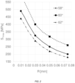
- FIG. 2 shows the evolution of a maximum stress in a back (S 1max ) as a function of the root radius (R) of the threading of the back for different angles of the threading of the back.
- FIG. 3 shows the evolution of a maximum stress in a back (S 1max ) as a function of the radius of the root radius (R) of the threading of the back for different assemblies having various characteristics in terms of back thread angles and middle thread.
- timepiece 200 One embodiment of a timepiece 200 is described hereinafter with reference to FIG. 1 .
- the timepiece 200 is for example a watch, in particular a wristwatch.
- the timepiece 200 includes a timepiece case 100 .
- the timepiece case 100 is intended to receive a movement in order to protect the latter from the external environment.
- the case is preferably sealed.
- the timepiece movement may be an electronic movement or a mechanical movement, in particular an automatic movement.
- the timepiece case comprises a first member 10 or first component and a second member 20 or second component that are intended to be screwed together.
- each of the two members includes a thread and one of the two members is screwed into the other by cooperation of the two threads.
- the two threads therefore have the same pitch and more generally, dimensional characteristics enabling them to cooperate with one another.
- the first timepiece member 10 includes a first axis A 10 and includes a first threading 11 having a pitch p and intended to cooperate with a second threading 21 provided on the second timepiece member 20 .
- the first threading is:
- Each threading comprises one or more threads and has a helical overall shape about the axis A 10 .
- Each thread is a helical portion the length of which measured along the axis is equal to the pitch.
- the root 15 of the threading is the junction between two flanks 16 of adjacent threads.
- the thread flanks 16 that is to say the sides of the threads, correspond to the parts situated between the crests 14 and the roots 15 of the threads.
- the crest 14 of a thread is the portion where the two flanks 16 of the same thread join.
- the first threading 11 preferably has a first thread angle 12
- the second threading 21 preferably has a second thread angle 22 and the value of the first thread angle 12 is 2 to 4 degrees greater than the value of the second thread angle 22 .
- a thread angle is defined as the angle that the two flanks of a thread form at the level of an axial section of the threading.
- one of the threadings has an appropriate thread angle in order for the flanks of the first threading of the first member to bear on or to be in contact against the flanks of the second threading of the second member, as previously stated, at the level of contact zones extending as close as possible to the roots of the threads of the first threading.
- the contact zones preferably extend at most over a distance (measured radially relative to the axis A 10 ) less than h/2 or less than h/4 or less than h/8 with h corresponding to the height of the threads of the first threading or to the height of the threads of the second threading.
- the thread angle difference between the first and second threadings must not significantly impact the behavior of the assembly, for example strength, seal, seizure, etc.
- the modification of the thread angle of the first threading so that the contact zone between the two threadings is moved in an appropriate manner may be determined as a function of the nominal dimensions of the second threading.
- a 2° to 4° increase in the thread angle of the first threading relative to the angle specified in the standard enables a reduction of tension stresses of the order of 20% as shown by the calculations of the inventors.
- the thread angle of the first threading is then between 62° and 64°. With such dimensions the contact between the thread flanks of the first member and the thread flanks of the second member is situated in the lower part of the flanks of the first threading, in the vicinity of the thread root of the first member.
- the threads of the first threading can be truncated to reduce the area of contact with a height of the threads of the first threading less than 0.3 pitch. This configuration makes it possible to prevent “point” bearing of the thread of the first threading generating increased stresses through a lever effect.
- the thread angles of the first and second threadings may be:
- the threads of the first threading may be truncated so that the crests of the axial sections of the threads of the first thread have a rectilinear or convex shape.
- the first threading preferably has a thread root radius r greater than 0.2 times the pitch of the first threading or greater than 0.4 times the pitch of the first threading.
- Optimizing the radius r of the root 15 of the thread also enables contribution to the reduction of tensile stresses in the first member, as shown in the graphs in FIGS. 2 and 3 .
- FIG. 2 shows the impact of the thread root radius on the stress to which the threading of the back is subjected for different thread angles of the back.
- FIG. 3 shows the use of a thread with a thread angle different from 60°.
- the choice of the thread standard has little influence on the aimed for performance. It is mainly the use of a greater angle, 2° to 4° greater than the usual values, on the threading of the back that enables reduction of the stress, whereas evolution of the thread angle to 55° or 65° has little influence.
- the first threading is preferably connected to a bearing surface 5 via a connecting fillet 13 having a radius greater than 0.4 times the pitch p of the first threading or greater than 0.8 times the pitch p of the first threading.
- This bearing surface extends radially outward from the first threading and is intended to come to bear against a second surface 25 provided on the second timepiece member.
- a seal may be disposed between these two surfaces in order to provide a seal between the two members.
- the connecting fillet 13 forms part of a groove or a cavity that has two groove walls and a groove bottom and makes the connection between the bearing plane 5 and the first threading 11 .
- a first groove wall may have a straight and/or curved axial section.
- the curvature may be defined by a groove radius 18 a .
- the groove wall On the bearing surface 5 side the groove wall may have a straight and/or curved axial section.
- the curvature may be defined by a groove radius 18 b.
- the groove bottom may have a “point” axial section, that is to say its axial section may be the point of intersection of the axial sections of the two groove walls.
- the groove bottom may be more extensive, as represented in FIG. 1 in which two curved portions 18 a and 18 b are connected by a straight section portion.
- the first member is also subjected to tensile stresses in the vicinity of this groove.
- the metal first members For watch case type components, typically for back-middle assemblies, the metal first members have thread side groove radii 18 a and bearing plane side radii 18 b between 0.06 mm and 0.15 mm inclusive. Their nominal value is 0.05 mm.
- the thread side groove radii 18 a and bearing plane side radii 18 b may be identical or different.
- the thread side groove radius 18 a increases from 0.1 mm to 0.2 mm the value of the mechanical stresses is reduced by of the order of 20%. If the thread side groove radius 18 a increases from 0.1 mm to 0.4 mm the value of the mechanical stresses is reduced by of the order of 40%.
- the connecting angle between the groove and the bearing plane may be a right angle, an acute angle or an obtuse angle, with or without pitting of the material.
- connection between the groove and the bearing plane may be plane or recessed without impacting the tensile strength of the groove.
- the second threading 21 is preferably standardized.
- the second threading may be a threading conforming to an ISO standard or an NI HS standard or a UN standard or a BSPT standard or an NPT standard or an NPTF standard or a DIN standard or an MJ standard or a UNJ standard or in accordance with a Whitworth profile.
- the first threading is an external or exterior threading, that is to say produced on a projecting surface, for example on a surface of a shaft.
- the second threading is an internal or interior threading, that is to say produced on a recessed surface, for example on a surface of a bore.
- the first member is a fragile material back, in particular one made of ceramic or of sapphire or of zirconia of or glass, the first threading of which is subjected to tensile loads.
- the back is assembled to a second member that consists of a middle. That middle is made of a more ductile material, in particular from a metal or a metal alloy.
- the invention may be transposed to any other type of screw fastening in which a fragile material first member, in particular made of ceramic or of sapphire or of zirconia or of glass, cooperates with a second member made of a more ductile material, in particular a metal or a metal alloy, to produce an assembly.
- the invention may also be transposed to any other type of screw fastening where a fragile material first member, in particular made of ceramic or of sapphire or of zirconia or of glass, cooperates with a fragile material second member, in particular one made of ceramic or of sapphire or of zirconia or of glass, to produce an assembly.
- the first and second members are screwed one into the other so that they are mechanically stressed, the member constituting the screw being for example mechanically stressed in tension.
- the applied tightening torque must in particular be mastered in the case of a sealed or safety assembly. If it is too low, the system risks leaking or loosening; if it is too high there is a risk of the members, in particular one of the threads, being damaged or even broken.
- Curves for the usual materials make it possible to determine the limit value to be adopted before the nut-and-screw pair is damaged for predetermined dimensions in a given material and in a given normative frame of reference. No such curves exist for pairs of materials involving metal alloys and fragile materials such as a ceramic, sapphire, zirconia or glass.
- the seizing threshold of a pair of materials is defined by the value of the contact pressure at which a transfer of material occurs from one surface to the other. There exists a seizing threshold for each pair of materials. Apart from the surface state, that threshold depends on the chemical and/or metallurgical nature of each of the two materials in contact.
- seizure may occur in two steps, micro-seizure followed where applicable by total seizure.
- Micro-seizure occurs when the tension does not increase in a linear manner but in steps when the tightening torque increases. This is the case for example of microwelds produced and then broken by the tightening torque applied as and when they occur (this is the “stick-slip” phenomenon). Relative rotation remains possible between the elements but the tightening is disturbed. This phenomenon may be localized.
- Micro-seizure is generally accentuated as the tightening torque increases, up to total seizure. When there is total seizure all rotation is prevented.
- a prestressed threaded assembly can be disassembled provided that no seizure has occurred between the members after tightening. This implies that to guarantee that a threaded assembly can be disassembled certain precautions are necessary, inter alia in order to prevent any micro-seizure during initial tightening, preventing all corrosion in service and maintaining a correct coefficient of friction during the life of the assembly.
- Stainless steel, aluminum and titanium threadings are particularly subject to seizing.
- stainless steel assemblies are generally treated, for example with a lubricant or an “anti-seizing” coating. These treatments are liable to degrade over time.
- a ceramic member for example a zirconia member, in accordance with the invention has a lower probability of seizure than a metal member that it replaces.
- a zirconia member with a tightening torque of 5 N ⁇ m, no seizure or deformation has been observed, even without treatment of the metal part.
- the system also withstands higher tightening torques without seizure. For example, a torque of 10 N ⁇ m has been applied to a zirconia back in accordance with the invention assembled to a stainless steel middle without initiating seizure or deformation of the members, even without treatment of the metal part.
- the threading may be a ceramic-coated metal threading, that is to say a threading in which the thread surfaces consist of a ceramic coating.
- Ceramic coating can be obtained by thermal spraying of a ceramic, by surface treatment, by heat treatment or by any other appropriate technique.
- the invention makes it possible to minimize the risks of cracking or of chipping of the ceramic layer as well as those of seizure of the assembly.
- the base material is for example stainless steel, titanium, etc.
- the ceramic layer is for example a layer of oxidized ceramic (zirconia, alumina, aluminum titanate, etc.) or non-oxidized ceramic such as a nitride or a carbide (aluminum nitride, silicon nitride, silicon carbide, tungsten carbide, etc.).
- oxidized ceramic zirconia, alumina, aluminum titanate, etc.
- non-oxidized ceramic such as a nitride or a carbide (aluminum nitride, silicon nitride, silicon carbide, tungsten carbide, etc.).
- the invention it is possible to produce fragile material or metal alloy backs having the same or substantially the same geometries and able to be interchanged to cooperate with the same middle, in particular the same metal middle. Moreover, these backs can be mounted without it being necessary to modify the production or after sales service tools for fitting/removing the back, irrespective of the material from which the back is made.
- the invention it is possible to produce a sealed wristwatch case including a fragile material, in particular ceramic, sapphire, zirconia or glass, replacing a metal back without adaptation of the metal middle.
- the invention it is possible to modify the threading of the fragile material back in order to preserve its integrity during screwing, under tightening and use conditions identical to those of a metal back. Moreover, the seizure problems encountered with metal backs are avoided, even with tightening torques higher than those usually employed with metal alloy backs.
- the invention it is therefore possible specifically to determine the dimensions of a threading of a fragile type material member in order for the threading to resist the same ranges of stresses as a metal part that the member replaces and in order for the threading to be compatible with the standard threading, for example threading conforming to the Swiss watchmaking standards (NIHS).
- the dimensions take account of the order of magnitude of the stress fields and the probabilities of rupture of the fragile type material member.
- This design advantageously enables the easy replacement of a metallic back by a ceramic back without it being necessary to modify the design of the metal part that receives it and/or the tools for fitting/removing the back, while guaranteeing a conforming seal, secure assembly and minimized risks of seizure.
- the exterior and interior threads are machined in accordance with the same class with the same tolerance in order to be compatible and to maximize the area of contact between the exterior and interior threads. If the exterior and interior threads are machined in accordance with the same class, taking account of the tolerances, the flanks of the interior thread and the flanks of the exterior thread are contact over the largest possible area, the flanks being the “flattest” possible.
- an assembly in particular a timepiece case, comprises:
- the first and second members are advantageously connected by a threaded connection or screwed to one another.
- a timepiece includes such an assembly.
- this other aspect of the invention may include any combination of the features described in the present document.
Landscapes
- Engineering & Computer Science (AREA)
- Physics & Mathematics (AREA)
- General Physics & Mathematics (AREA)
- General Engineering & Computer Science (AREA)
- Mechanical Engineering (AREA)
- Manufacturing & Machinery (AREA)
- Adornments (AREA)
- Connection Of Plates (AREA)
Applications Claiming Priority (3)
| Application Number | Priority Date | Filing Date | Title |
|---|---|---|---|
| EP20185189.6 | 2020-07-10 | ||
| EP20185189 | 2020-07-10 | ||
| EP20185189.6A EP3936732B1 (fr) | 2020-07-10 | 2020-07-10 | Organe horloger fileté |
Publications (2)
| Publication Number | Publication Date |
|---|---|
| US20220066393A1 US20220066393A1 (en) | 2022-03-03 |
| US11880169B2 true US11880169B2 (en) | 2024-01-23 |
Family
ID=71575146
Family Applications (1)
| Application Number | Title | Priority Date | Filing Date |
|---|---|---|---|
| US17/372,033 Active 2042-07-13 US11880169B2 (en) | 2020-07-10 | 2021-07-09 | Threaded timepiece member |
Country Status (4)
| Country | Link |
|---|---|
| US (1) | US11880169B2 (fr) |
| EP (1) | EP3936732B1 (fr) |
| JP (1) | JP7737831B2 (fr) |
| CN (1) | CN113985716B (fr) |
Citations (17)
| Publication number | Priority date | Publication date | Assignee | Title |
|---|---|---|---|---|
| US378959A (en) * | 1888-03-06 | Petee heney | ||
| US403511A (en) * | 1889-05-21 | William w | ||
| US1661232A (en) * | 1925-10-30 | 1928-03-06 | Hans Wilsdorf | Keyless watch |
| US1910908A (en) * | 1931-03-31 | 1933-05-23 | Wadsworth Watch Case Co | Watchcase |
| US2482317A (en) * | 1944-06-28 | 1949-09-20 | Rolex Watch Co Ltd | Tight winding device for watches |
| CH486059A (fr) | 1966-09-23 | 1970-02-15 | Boites De Montres F Kuhn S A F | Boîte de montre étanche |
| US3535869A (en) * | 1967-08-22 | 1970-10-27 | Nationale Sa | Water-tight winding stem for a timepiece |
| CH1359773A4 (fr) | 1973-09-21 | 1976-07-30 | Rolex Montres | Boîte de montre |
| US4313187A (en) * | 1980-01-24 | 1982-01-26 | Citizen Watch Co., Ltd. | Water resisting crown structure for electronic wristwatches |
| EP0520224A1 (fr) | 1991-06-27 | 1992-12-30 | Montres Rado S.A. | Boîte de montre-bracelet comportant un fond remontant le long de la carrure |
| US5257247A (en) * | 1992-02-07 | 1993-10-26 | Smh Management Services Ag | Safety valve for diver's timepiece |
| EP0575277A1 (fr) | 1992-06-17 | 1993-12-22 | AEROSPATIALE Société Nationale Industrielle | Visserie en matériau composite constitué d'une matrice céramique renforcée de fibres réfractaires |
| US6872899B2 (en) * | 2003-03-31 | 2005-03-29 | Seiko Epson Corporation | Lockable pushbutton actuator for a display device such as a watch |
| US6987708B2 (en) * | 2000-11-11 | 2006-01-17 | Junghans Uhren Gmbh | Emergency call transmitter incorporated in a wristwatch |
| EP1916576A1 (fr) | 2007-07-02 | 2008-04-30 | Rolex Sa | Boîte de montre-bracelet étanche |
| WO2013072389A1 (fr) | 2011-11-15 | 2013-05-23 | Dc Swiss Sa | Système d'assemblage fileté autobloquant |
| EP3276432A1 (fr) | 2016-07-26 | 2018-01-31 | Omega SA | Sous-ensemble d'habillage pour piece d'horlogerie ou montre ou bijou |
Family Cites Families (11)
| Publication number | Priority date | Publication date | Assignee | Title |
|---|---|---|---|---|
| US5580199A (en) * | 1993-06-29 | 1996-12-03 | Kabushiki Kaisha Suzuki Rashi Seisakusho | Fastening screw |
| JP2989129B2 (ja) * | 1995-10-09 | 1999-12-13 | イワタボルト株式会社 | 雄ねじ |
| US7698989B2 (en) * | 2002-07-04 | 2010-04-20 | Luk Fahrzeug-Hydraulik Gmbh & Co. Kg | Reciprocating piston machine |
| JPWO2004048785A1 (ja) * | 2002-11-22 | 2006-03-23 | 杉村 宣行 | めねじ及びめねじを用いたアキュムレータ |
| EP1775050A1 (fr) * | 2005-10-14 | 2007-04-18 | Eric Bouille | Ensemble de boîtes de montre |
| EP2176559B1 (fr) * | 2007-08-13 | 2014-10-08 | Research Engineering&Manufacturing, Inc. | Pièce de fixation formant filet |
| CH705089A2 (fr) * | 2011-06-08 | 2012-12-14 | Omega Sa | Dispositif et procédé de fixation d'un élément de montre avec orientation angulaire réglable. |
| CH708049A2 (fr) * | 2013-05-14 | 2014-11-14 | Safelock Sa | Système d'assemblage fileté autobloquant. |
| FR3027649A1 (fr) * | 2014-10-24 | 2016-04-29 | Vallourec Oil & Gas France | Protecteur de connexion d'un composant tubulaire |
| WO2018079137A1 (fr) * | 2016-10-28 | 2018-05-03 | 株式会社トープラ | Filetage mâle et structure de fixation par filetage |
| CN106438657A (zh) * | 2016-12-07 | 2017-02-22 | 石文祥 | 螺距过盈配合螺纹、螺纹连接件以及修正螺纹加工工具 |
-
2020
- 2020-07-10 EP EP20185189.6A patent/EP3936732B1/fr active Active
-
2021
- 2021-06-30 JP JP2021108481A patent/JP7737831B2/ja active Active
- 2021-07-08 CN CN202110773687.2A patent/CN113985716B/zh active Active
- 2021-07-09 US US17/372,033 patent/US11880169B2/en active Active
Patent Citations (18)
| Publication number | Priority date | Publication date | Assignee | Title |
|---|---|---|---|---|
| US378959A (en) * | 1888-03-06 | Petee heney | ||
| US403511A (en) * | 1889-05-21 | William w | ||
| US1661232A (en) * | 1925-10-30 | 1928-03-06 | Hans Wilsdorf | Keyless watch |
| US1910908A (en) * | 1931-03-31 | 1933-05-23 | Wadsworth Watch Case Co | Watchcase |
| US2482317A (en) * | 1944-06-28 | 1949-09-20 | Rolex Watch Co Ltd | Tight winding device for watches |
| CH486059A (fr) | 1966-09-23 | 1970-02-15 | Boites De Montres F Kuhn S A F | Boîte de montre étanche |
| US3535869A (en) * | 1967-08-22 | 1970-10-27 | Nationale Sa | Water-tight winding stem for a timepiece |
| CH1359773A4 (fr) | 1973-09-21 | 1976-07-30 | Rolex Montres | Boîte de montre |
| US4313187A (en) * | 1980-01-24 | 1982-01-26 | Citizen Watch Co., Ltd. | Water resisting crown structure for electronic wristwatches |
| EP0520224A1 (fr) | 1991-06-27 | 1992-12-30 | Montres Rado S.A. | Boîte de montre-bracelet comportant un fond remontant le long de la carrure |
| US5257247A (en) * | 1992-02-07 | 1993-10-26 | Smh Management Services Ag | Safety valve for diver's timepiece |
| EP0575277A1 (fr) | 1992-06-17 | 1993-12-22 | AEROSPATIALE Société Nationale Industrielle | Visserie en matériau composite constitué d'une matrice céramique renforcée de fibres réfractaires |
| US5405227A (en) | 1992-06-17 | 1995-04-11 | Societe Nationale Industrielle Et Aerospatiale | Fasteners made of composite material of a ceramic matrix reinforced with refractory fibers |
| US6987708B2 (en) * | 2000-11-11 | 2006-01-17 | Junghans Uhren Gmbh | Emergency call transmitter incorporated in a wristwatch |
| US6872899B2 (en) * | 2003-03-31 | 2005-03-29 | Seiko Epson Corporation | Lockable pushbutton actuator for a display device such as a watch |
| EP1916576A1 (fr) | 2007-07-02 | 2008-04-30 | Rolex Sa | Boîte de montre-bracelet étanche |
| WO2013072389A1 (fr) | 2011-11-15 | 2013-05-23 | Dc Swiss Sa | Système d'assemblage fileté autobloquant |
| EP3276432A1 (fr) | 2016-07-26 | 2018-01-31 | Omega SA | Sous-ensemble d'habillage pour piece d'horlogerie ou montre ou bijou |
Non-Patent Citations (1)
| Title |
|---|
| Office Action dated Jan. 13, 2021 in counterpart EP application No. 20185189.6. (5 pages). |
Also Published As
| Publication number | Publication date |
|---|---|
| US20220066393A1 (en) | 2022-03-03 |
| JP2022016326A (ja) | 2022-01-21 |
| JP7737831B2 (ja) | 2025-09-11 |
| CN113985716A (zh) | 2022-01-28 |
| EP3936732A1 (fr) | 2022-01-12 |
| EP3936732B1 (fr) | 2023-03-15 |
| CN113985716B (zh) | 2025-05-23 |
Similar Documents
| Publication | Publication Date | Title |
|---|---|---|
| US2152681A (en) | Screw connection | |
| AU721242B2 (en) | Threaded fastener system | |
| US4432682A (en) | Threaded fastener assembly | |
| CN102639912B (zh) | 螺纹连接件 | |
| AU2015367486B2 (en) | Threaded connection | |
| US20010002963A1 (en) | Thread and screw connection for high application temperatures | |
| CN105308257B (zh) | 用于钻探和开采油气井的螺纹连接件的制造方法、以及生成的螺纹连接件 | |
| CN101861467B (zh) | 螺纹成型紧固件 | |
| NO313602B1 (no) | Gjengeforbindelse for rör og fremgangsmåte for dannelse av en slik gjengeforbindelse | |
| NO315292B1 (no) | Gjengeforbindelsesanordning for metallrör og fremgangsmåte for dannelse avdenne | |
| CA2930207C (fr) | Ensemble pour produire une liaison filetee pour forage et fonctionnement de puits d'hydrocarbures, et liaison filetee resultante | |
| CN108457958A (zh) | 用于过盈配合紧固件的圆角引入 | |
| CN110382812B (zh) | 用于管件的螺纹接头 | |
| NO864974L (no) | Roerforbindelse for olje- og gassfeltroer. | |
| WO2015154614A1 (fr) | Procédé anti-desserrage à double boulon | |
| US20240376925A1 (en) | Threaded Fastener Having a Thread Crest Greater than Its Thread Root and V Angles on the Crest and Root | |
| US10595597B2 (en) | Assembly screw for assembling two horology components | |
| US20220066393A1 (en) | Threaded timepiece member | |
| CN1210578A (zh) | 具有用于连接缸衬套的封闭件的可旋紧的用压力介质操纵的工作缸 | |
| US20070117066A1 (en) | Implant arrangement with an internal socket for a turning tool | |
| US7066209B2 (en) | Thread protector | |
| CN101449023A (zh) | 油井管的螺纹连接件 | |
| JP7141622B2 (ja) | 締結用ナット | |
| JP2002250326A (ja) | 座金組込みボルト | |
| SU1751483A1 (ru) | Самостопор ща с гайка |
Legal Events
| Date | Code | Title | Description |
|---|---|---|---|
| FEPP | Fee payment procedure |
Free format text: ENTITY STATUS SET TO UNDISCOUNTED (ORIGINAL EVENT CODE: BIG.); ENTITY STATUS OF PATENT OWNER: LARGE ENTITY |
|
| STPP | Information on status: patent application and granting procedure in general |
Free format text: DOCKETED NEW CASE - READY FOR EXAMINATION |
|
| STPP | Information on status: patent application and granting procedure in general |
Free format text: NOTICE OF ALLOWANCE MAILED -- APPLICATION RECEIVED IN OFFICE OF PUBLICATIONS |
|
| AS | Assignment |
Owner name: ROLEX SA, SWITZERLAND Free format text: ASSIGNMENT OF ASSIGNORS INTEREST;ASSIGNORS:JUNOD, BENOIT;NAGEL, PATRICE;ROBIN, JEAN-BAPTISTE;SIGNING DATES FROM 20231111 TO 20231204;REEL/FRAME:065844/0858 |
|
| STPP | Information on status: patent application and granting procedure in general |
Free format text: PUBLICATIONS -- ISSUE FEE PAYMENT VERIFIED |
|
| STCF | Information on status: patent grant |
Free format text: PATENTED CASE |