US12001900B2 - Inkjet printing method and inkjet printing device - Google Patents
Inkjet printing method and inkjet printing device Download PDFInfo
- Publication number
- US12001900B2 US12001900B2 US17/765,998 US202017765998A US12001900B2 US 12001900 B2 US12001900 B2 US 12001900B2 US 202017765998 A US202017765998 A US 202017765998A US 12001900 B2 US12001900 B2 US 12001900B2
- Authority
- US
- United States
- Prior art keywords
- dots
- printing
- printed
- distance
- region
- Prior art date
- Legal status (The legal status is an assumption and is not a legal conclusion. Google has not performed a legal analysis and makes no representation as to the accuracy of the status listed.)
- Active, expires
Links
Images




Classifications
-
- B—PERFORMING OPERATIONS; TRANSPORTING
- B41—PRINTING; LINING MACHINES; TYPEWRITERS; STAMPS
- B41J—TYPEWRITERS; SELECTIVE PRINTING MECHANISMS, i.e. MECHANISMS PRINTING OTHERWISE THAN FROM A FORME; CORRECTION OF TYPOGRAPHICAL ERRORS
- B41J2/00—Typewriters or selective printing mechanisms characterised by the printing or marking process for which they are designed
- B41J2/005—Typewriters or selective printing mechanisms characterised by the printing or marking process for which they are designed characterised by bringing liquid or particles selectively into contact with a printing material
- B41J2/01—Ink jet
- B41J2/21—Ink jet for multi-colour printing
-
- G—PHYSICS
- G06—COMPUTING OR CALCULATING; COUNTING
- G06K—GRAPHICAL DATA READING; PRESENTATION OF DATA; RECORD CARRIERS; HANDLING RECORD CARRIERS
- G06K15/00—Arrangements for producing a permanent visual presentation of the output data, e.g. computer output printers
- G06K15/02—Arrangements for producing a permanent visual presentation of the output data, e.g. computer output printers using printers
- G06K15/10—Arrangements for producing a permanent visual presentation of the output data, e.g. computer output printers using printers by matrix printers
- G06K15/102—Arrangements for producing a permanent visual presentation of the output data, e.g. computer output printers using printers by matrix printers using ink jet print heads
- G06K15/105—Multipass or interlaced printing
-
- B—PERFORMING OPERATIONS; TRANSPORTING
- B41—PRINTING; LINING MACHINES; TYPEWRITERS; STAMPS
- B41J—TYPEWRITERS; SELECTIVE PRINTING MECHANISMS, i.e. MECHANISMS PRINTING OTHERWISE THAN FROM A FORME; CORRECTION OF TYPOGRAPHICAL ERRORS
- B41J29/00—Details of, or accessories for, typewriters or selective printing mechanisms not otherwise provided for
- B41J29/38—Drives, motors, controls or automatic cut-off devices for the entire printing mechanism
-
- B—PERFORMING OPERATIONS; TRANSPORTING
- B41—PRINTING; LINING MACHINES; TYPEWRITERS; STAMPS
- B41J—TYPEWRITERS; SELECTIVE PRINTING MECHANISMS, i.e. MECHANISMS PRINTING OTHERWISE THAN FROM A FORME; CORRECTION OF TYPOGRAPHICAL ERRORS
- B41J11/00—Devices or arrangements of selective printing mechanisms, e.g. ink-jet printers or thermal printers, for supporting or handling copy material in sheet or web form
- B41J11/0015—Devices or arrangements of selective printing mechanisms, e.g. ink-jet printers or thermal printers, for supporting or handling copy material in sheet or web form for treating before, during or after printing or for uniform coating or laminating the copy material before or after printing
- B41J11/002—Curing or drying the ink on the copy materials, e.g. by heating or irradiating
- B41J11/0021—Curing or drying the ink on the copy materials, e.g. by heating or irradiating using irradiation
- B41J11/00214—Curing or drying the ink on the copy materials, e.g. by heating or irradiating using irradiation using UV radiation
-
- B—PERFORMING OPERATIONS; TRANSPORTING
- B41—PRINTING; LINING MACHINES; TYPEWRITERS; STAMPS
- B41J—TYPEWRITERS; SELECTIVE PRINTING MECHANISMS, i.e. MECHANISMS PRINTING OTHERWISE THAN FROM A FORME; CORRECTION OF TYPOGRAPHICAL ERRORS
- B41J29/00—Details of, or accessories for, typewriters or selective printing mechanisms not otherwise provided for
- B41J29/38—Drives, motors, controls or automatic cut-off devices for the entire printing mechanism
- B41J29/393—Devices for controlling or analysing the entire machine ; Controlling or analysing mechanical parameters involving printing of test patterns
-
- B—PERFORMING OPERATIONS; TRANSPORTING
- B41—PRINTING; LINING MACHINES; TYPEWRITERS; STAMPS
- B41J—TYPEWRITERS; SELECTIVE PRINTING MECHANISMS, i.e. MECHANISMS PRINTING OTHERWISE THAN FROM A FORME; CORRECTION OF TYPOGRAPHICAL ERRORS
- B41J3/00—Typewriters or selective printing or marking mechanisms characterised by the purpose for which they are constructed
- B41J3/407—Typewriters or selective printing or marking mechanisms characterised by the purpose for which they are constructed for marking on special material
-
- B—PERFORMING OPERATIONS; TRANSPORTING
- B41—PRINTING; LINING MACHINES; TYPEWRITERS; STAMPS
- B41J—TYPEWRITERS; SELECTIVE PRINTING MECHANISMS, i.e. MECHANISMS PRINTING OTHERWISE THAN FROM A FORME; CORRECTION OF TYPOGRAPHICAL ERRORS
- B41J3/00—Typewriters or selective printing or marking mechanisms characterised by the purpose for which they are constructed
- B41J3/407—Typewriters or selective printing or marking mechanisms characterised by the purpose for which they are constructed for marking on special material
- B41J3/4075—Tape printers; Label printers
-
- B—PERFORMING OPERATIONS; TRANSPORTING
- B41—PRINTING; LINING MACHINES; TYPEWRITERS; STAMPS
- B41M—PRINTING, DUPLICATING, MARKING, OR COPYING PROCESSES; COLOUR PRINTING
- B41M3/00—Printing processes to produce particular kinds of printed work, e.g. patterns
- B41M3/008—Sequential or multiple printing, e.g. on previously printed background; Mirror printing; Recto-verso printing; using a combination of different printing techniques; Printing of patterns visible in reflection and by transparency; by superposing printed artifacts
-
- B—PERFORMING OPERATIONS; TRANSPORTING
- B41—PRINTING; LINING MACHINES; TYPEWRITERS; STAMPS
- B41M—PRINTING, DUPLICATING, MARKING, OR COPYING PROCESSES; COLOUR PRINTING
- B41M3/00—Printing processes to produce particular kinds of printed work, e.g. patterns
- B41M3/06—Veined printings; Fluorescent printings; Stereoscopic images; Imitated patterns, e.g. tissues, textiles
-
- B—PERFORMING OPERATIONS; TRANSPORTING
- B41—PRINTING; LINING MACHINES; TYPEWRITERS; STAMPS
- B41M—PRINTING, DUPLICATING, MARKING, OR COPYING PROCESSES; COLOUR PRINTING
- B41M5/00—Duplicating or marking methods; Sheet materials for use therein
- B41M5/0041—Digital printing on surfaces other than ordinary paper
- B41M5/0047—Digital printing on surfaces other than ordinary paper by ink-jet printing
-
- B—PERFORMING OPERATIONS; TRANSPORTING
- B41—PRINTING; LINING MACHINES; TYPEWRITERS; STAMPS
- B41M—PRINTING, DUPLICATING, MARKING, OR COPYING PROCESSES; COLOUR PRINTING
- B41M5/00—Duplicating or marking methods; Sheet materials for use therein
- B41M5/0041—Digital printing on surfaces other than ordinary paper
- B41M5/0064—Digital printing on surfaces other than ordinary paper on plastics, horn, rubber, or other organic polymers
-
- B—PERFORMING OPERATIONS; TRANSPORTING
- B41—PRINTING; LINING MACHINES; TYPEWRITERS; STAMPS
- B41M—PRINTING, DUPLICATING, MARKING, OR COPYING PROCESSES; COLOUR PRINTING
- B41M7/00—After-treatment of prints, e.g. heating, irradiating, setting of the ink, protection of the printed stock
- B41M7/0045—After-treatment of prints, e.g. heating, irradiating, setting of the ink, protection of the printed stock using protective coatings or film forming compositions cured by mechanical wave energy, e.g. ultrasonics, cured by electromagnetic radiation or waves, e.g. ultraviolet radiation, electron beams, or cured by magnetic or electric fields, e.g. electric discharge, plasma
-
- B—PERFORMING OPERATIONS; TRANSPORTING
- B41—PRINTING; LINING MACHINES; TYPEWRITERS; STAMPS
- B41M—PRINTING, DUPLICATING, MARKING, OR COPYING PROCESSES; COLOUR PRINTING
- B41M7/00—After-treatment of prints, e.g. heating, irradiating, setting of the ink, protection of the printed stock
- B41M7/0081—After-treatment of prints, e.g. heating, irradiating, setting of the ink, protection of the printed stock using electromagnetic radiation or waves, e.g. ultraviolet radiation, electron beams
Definitions
- One aspect of the present invention relates to an inkjet printing method and an inkjet printing device.
- Patent Document 1 Conventionally, one described in Patent Document 1 has been known as an inkjet printing method.
- JP 2015-96321 A after performing color printing on a printing surface, an overcoat layer is formed on an ink layer produced by the color printing by an inkjet method. This enhances a gloss of the printing surface.
- the inkjet printing method of Patent Document 1 allows forming a so-called glossy gloss layer on the printing surface.
- a decorative printed layer having a three-dimensional texture, such as a matte layer on an entire surface or a desired part by inkjet printing has been required.
- An object of one aspect of the present invention is to provide an inkjet printing method and an inkjet printing device that can excellently form a decorative printed layer having a three-dimensional texture.
- An inkjet printing method forms a decorative printed layer having a three-dimensional texture on a printing surface.
- the inkjet printing method includes: printing dots of curable ink that cure under a predetermined condition based on dot pattern data indicative of printed positions of the dots to be printed on the printing surface; and curing the printed dots.
- the dot pattern data indicates that: a distance between the adjacent dots becomes a distance where the adjacent dots before the curing are allowed to be maintained independently without bonding to one another in a first region; and the distance between the adjacent dots becomes a distance where the adjacent dots before the curing bond to one another in a second region different from the first region.
- An inkjet printing method forms a decorative printed layer having a three-dimensional texture on a printing surface.
- the inkjet printing method includes: acquiring dot pattern data indicative of printed positions of dots to be printed on the printing surface corresponding to gloss level information indicative of glossiness in a region in the printing surface; printing the dots of curable ink based on the dot pattern data; and curing the printed dots.
- the dot pattern data indicates that: a distance between the adjacent dots becomes a distance where the adjacent dots before the curing are allowed to be maintained independently without bonding to one another when the gloss level information indicates that the gloss level information is lower than a specific glossiness; and the distance between the adjacent dots becomes a distance where the adjacent dots before the curing bond to one another when the gloss level information indicates that the gloss level information is higher than the specific glossiness.
- An inkjet printing device forms a decorative printed layer having a three-dimensional texture on a printing surface.
- the inkjet printing device includes a printing unit, a curing unit, a processor, and a medium.
- the printing unit is configured to eject curable ink that cures under a predetermined condition.
- the medium includes a series of pieces of instruction information executable by the processor and usable by a computer connected to the processor.
- the instruction information causes the printing unit to print dots of the curable ink based on dot pattern data indicative of printed positions of the dots to be printed on the printing surface; and controls the curing unit so as to cure the printed dots.
- the dot pattern data indicates that: a distance between the adjacent dots becomes a distance where the adjacent dots before the curing are allowed to be maintained independently without bonding to one another in a first region; and the distance between the adjacent dots becomes a distance where the adjacent dots before the curing bond to one another in a second region different from the first region.
- the inkjet printing method and the inkjet printing device that can excellently form the decorative printed layer having the three-dimensional texture by control to a desired gloss level.
- FIGS. 1 A and 1 B are plan views of a printed material.
- FIGS. 2 A to 2 C are partial cross-sectional views of the printed material.
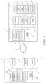
- FIG. 3 is a block configuration diagram of an inkjet printing device according to an embodiment.
- FIG. 4 is a flow chart depicting contents of an inkjet printing method.
- FIG. 5 is a flow chart depicting contents of a dot pattern data acquiring process.
- FIG. 6 is a flow chart depicting the contents of the inkjet printing method.
- FIG. 7 is a flow chart depicting the contents of the inkjet printing method.
- FIGS. 8 A to 8 D are schematic views illustrating a state when a matte layer is formed.
- FIGS. 9 A and 9 B are schematic views illustrating a state when a gloss layer is formed.
- FIG. 10 is a conceptual drawing illustrating an example of information of dot pattern data.
- FIG. 11 is a conceptual drawing for explaining contents of multi-pass printing.
- FIGS. 12 A and 12 B are conceptual drawings for explaining an action and an effect.
- the printed material 50 is a sheet-shaped member having a surface printed by the inkjet printing device 1 .
- the printed material 50 is configured by forming a color printed layer 52 on a base material 51 and forming a decorative printed layer 53 on the color printed layer 52 .
- the base material 51 is a target to be printed, for example, a member made from a material, such as vinyl chloride resin, acrylic resin, urethane resin, polyester resin, and a paper is employed.
- the color printed layer 52 is a layer formed by inkjet printing of color ink by the inkjet printing device 1 .
- the color ink is resin containing a pigment, such as cyan, magenta, yellow, or black, and is ink that contains a solvent and fixed by drying or ink that contains a photoinitiator and a photocurable monomer and curable by light.
- the decorative printed layer 53 may be directly formed on the base material 51 without the color printed layer 52 .
- the decorative printed layer 53 is a printed layer having a three-dimensional texture (see FIGS. 2 A to 2 C ).
- the three-dimensional texture is a layer formed so as to bulge from the printing surface 57 having a predetermined height at least greater than a thickness of the color printed layer 52 .
- the decorative printed layer 53 is a layer that forms glossiness and a texture on the surface of the printed material 50 .
- the decorative printed layer 53 is formed using curable ink that cures under predetermined conditions. In other words, curing the printed curable ink forms the decorative printed layer 53 .
- the curing conditions of the curable ink are not particularly limited.
- the curable ink may be cured by radiation irradiation (such as ultraviolet light) and may be cured under heating conditions.
- the curable ink may be colorless and transparent.
- the decorative printed layer 53 may be formed using colored curable ink.
- a radiation curable ink composition and a thermosetting ink composition may be used as the material of the curable ink. Examples of the radiation curable ink composition include a mixture containing an acrylic monomer and a photopolymerization initiator.
- the printed material 50 has a first region E 1 and a second region E 2 .
- the first region E 1 is a region where a matte layer 53 A is formed as the decorative printed layer 53 .
- the second region E 2 is a region where a gloss layer 53 B is formed as the decorative printed layer 53 .
- the printed material 50 may be constituted only by the first region E 1 where the matte layer 53 A is formed.
- FIG. 2 A is a cross-sectional view of the first region E 1 where the matte layer 53 A is formed.
- the matte layer 53 A is a layer in which a shape of the surface is changed so as to have three-dimensional irregularities to reduce a gloss level indicative of glossiness.
- FIG. 2 B is a cross-sectional view of the second region E 2 where the gloss layer 53 B is formed.
- the gloss layer 53 B is a layer whose surface is formed so as to have a smooth planar shape to increase the gloss level indicative of the glossiness.
- both can be distinguished that measured values by a 60-degree glossmeter are relatively different by 10 or more, preferably 20 or more, and more preferably 30 or more.
- a foundation layer 56 that changes in shape in a three-dimensional manner may be formed in advance, and the matte layer 53 A may be formed on a surface of the foundation layer 56 .
- the surface of the color printed layer 52 , the surface of the foundation layer 56 in FIG. 2 C , and the surface of the base material 51 in the case of direct printing on the base material 51 correspond to a printing surface 57 of the decorative printed layer 53 .
- the inkjet printing device 1 is a device for forming the decorative printed layer 53 having the three-dimensional texture on the printing surface.
- the inkjet printing device 1 is connected to a terminal device 20 over a network 19 , and is operated by the terminal device 20 . However, the operation may be directly performed by the inkjet printing device 1 without via the terminal device 20 .
- the inkjet printing device 1 includes a memory 2 , a processor 3 , a communication interface 4 , an input interface 6 , a display 7 , a print control unit 8 , and a printing unit 9 .
- the memory 2 , the processor 3 , the communication interface 4 , the input interface 6 , the display 7 , and the print control unit 8 are mutually connected by connection means 10 using a communication path or a signal line.
- the print control unit 8 is connected to the printing unit 9 .
- the memory 2 holds various kinds of information for operating the inkjet printing device 1 .
- the memory 2 includes a series of pieces of instruction information executable by the processor 3 and constitutes a medium usable by a computer connected to the processor 3 .
- the memory 2 includes a RAM/ROM 11 and a storage unit 12 .
- the processor 3 executes, for example, an operating system and an application program in the inkjet printing device 1 .
- the communication interface 4 is a device that communicates with an external device to exchange information.
- the input interface 6 is a device for inputting information from outside.
- the display 7 is a device for displaying the information.
- Each functional element of the inkjet printing device 1 is achieved by loading predetermined software on the processor 3 or the memory 2 and executing the software.
- the processor 3 causes the communication interface 4 , the input interface 6 , the display 7 , and the print control unit 8 to operate in accordance with the software to read and write data in the memory 2 .
- Data or a database necessary for the process are stored in the memory.
- the print control unit 8 controls printing by the printing unit 9 .
- the print control unit 8 transmits control signals to respective components of the printing unit 9 for control.
- the printing unit 9 includes a conveying unit 14 , an image printing unit 16 , a dot printing unit 17 (printing unit), and a curing unit 18 .
- the conveying unit 14 is a mechanism that conveys the base material 51 , which is the target for printing, to the image printing unit 16 , the dot printing unit 17 , and the curing unit 18 .
- the image printing unit 16 generates the color printed layer 52 produced by ejecting color ink and reproducing an image based on acquired image data.
- the dot printing unit 17 ejects the curable ink based on dot pattern data to generate the decorative printed layer 53 .
- the curing unit 18 is a mechanism for curing the curable ink. For example, when the curable ink is cured by ultraviolet light, the curing unit 18 includes an ultraviolet irradiation unit.
- the terminal device 20 includes a memory 22 , a processor 23 , a communication interface 24 , an input interface 26 , and a display 27 .
- the memory 22 , the processor 23 , the communication interface 24 , the input interface 26 , and the display 27 are mutually connected by connection means 29 using a communication path or a signal line.
- the memory 22 includes a determination table 33 , a RAM/ROM 31 , and a storage unit 32 .
- the determination table 33 is various determination conditions necessary to perform printing by the inkjet printing device 1 .
- the processor 23 , the communication interface 24 , the input interface 26 , and the display 27 have functions of same purposes as those that have been described in the description of the inkjet printing device, and thus descriptions thereof will be omitted.
- This method forms the decorative printed layer 53 having the three-dimensional texture on the printing surface 57 .
- respective steps in the following description are performed by causing the print control unit 8 to operate by the processor with a memory based on a series of pieces of instruction information that can be performed by the processor.
- the print control unit 8 controls each component of the printing unit 9 based on the instruction information.
- the inkjet printing method includes a dot pattern data acquiring step (Step S 100 ), a printing step (Step S 110 ), a curing step (Step S 120 ), and a repetitive determining step (Step S 130 ).
- the inkjet printing method includes a repetitive step (Step S 140 ) that repeatedly determines the printing step S 110 , the curing step S 120 , and the repetitive determining step S 130 (Step S 140 ).
- the first printing in the repetition is referred to as the “first pass”
- the second printing is referred to as the “second pass”
- the M-th printing is referred to as the “M-th pass.”
- the print control unit 8 acquires the dot pattern data.
- the dot pattern data is information indicating how the dot printing unit 17 in the inkjet printing device 1 prints dots of the curable ink on the printing surface 57 .
- the dot pattern data may be generated by the terminal device 20 or may be generated by the inkjet printing device 1 .
- the dot pattern data indicates printing positions of dots 40 to be printed on the printing surface 57 .
- the dot data also holds positional information of the dots 40 in each pass.
- FIGS. 8 A to 8 D are schematic views illustrating a state when the matte layer is formed. An X direction in FIGS.
- the dot pattern data holds positional information of a position P 1 of the dot 40 printed in the first pass ( FIG. 8 A ), positional information of a position P 2 of the dot 40 printed in the second pass ( FIG. 8 C ), and positional information of a position P 3 of the dot 40 printed in the third pass ( FIG. 8 D ).
- the printed positions of the dots 40 on the printing surface 57 are filled with black.
- the dot pattern data indicates that a distance between the adjacent dots 40 in the first region E 1 where the matte layer 53 A is formed becomes a distance where the adjacent dots 40 before the curing are allowed to be maintained independently without bonding to one another. Meanwhile, the dot pattern data indicates that a distance between the adjacent dots 40 in the second region E 2 where the gloss layer 53 B is formed becomes a distance where the adjacent dots 40 before the curing bond to one another.
- the dot pattern data employs the positional relationship illustrated in FIGS. 8 A and 8 B to form the matte layer 53 A, and employs the positional relationship illustrated in FIGS. 9 A and 9 B to form the gloss layer 53 B.
- a center-to-center distance of the adjacent dots 40 can be configured to be 105 ⁇ m or greater with an ink diameter of 100 ⁇ m.
- the positional relationship of FIGS. 9 A and 9 B may be employed similarly to the gloss layer 53 B up to a thickness to some extent, and the positional relationship of FIGS. 8 A and 8 B may be employed only to the vicinity of the surface of the matte layer 53 A. That is, at least the dot pattern data corresponding to the step of printing of the last dots 40 may indicate that the distance between the adjacent dots 40 in the first region E 1 where the matte layer 53 A is formed becomes a distance where the adjacent dots 40 before the curing are allowed to be maintained independently without bonding to one another.
- the first region E 1 includes a plurality of pattern regions separated into a predetermined number of sections (see also FIGS. 2 A to 2 C ).
- the dot pattern data indicates an order of the printing of the dots 40 on the respective sections in the pattern region.
- FIG. 10 describes orders of the paths in which the dots 40 are printed in the sections.
- the dots 40 are printed on the sections denoted as “1” in the first pass, and the dots 40 are printed on the sections denoted as “2” in the second pass.
- the dot 40 formed on the certain pattern region in the N-th path is separated from the dot 40 formed on the adjacent pattern region in the N-th path by a distance where the adjacent dots 40 are allowed to be maintained independently without bonding to one another.
- the pattern region is separated into the “3 ⁇ 4” sections.
- the printing orders of the dots 40 are set aligned by a fixed rule from the first to the twelfth paths.
- the sections where the dots 40 are formed in the certain pattern region in the first pass are colored, and sufficient distances are ensured to one another in the sections.
- the dots 40 may be printed on the randomly selected sections in the pattern region. Furthermore, the number of the sections where the dots 40 are printed in the repetitive step S 140 may be less than the number of sections BB in the pattern region. For example, in an example illustrated in FIG. 10 B 10 , the printing orders of the dots 40 are randomly set in the pattern region. In addition, although the pattern region is separated into the total 48 sections of “6 ⁇ 8,” the sections BB where the dots 40 are not printed are present in the pattern region. Also, the dots 40 are formed in the plurality of sections in the pattern region in one-time pass. For example, the dots 40 are printed on the four sections in the tenth pass.
- the dot 40 formed on the certain pattern region in the N-th path is separated from the dot 40 in the same pattern region and the dot 40 formed on the adjacent pattern region in the N-th path by a distance where the dots 40 are allowed to be maintained independently without bonding to one another.
- the dot pattern data may be in a raster image format.
- the raster image is a data format in which one pixel-points are arranged in a grid pattern vertically and horizontally.
- the dot pattern data may also include information indicative of sizes of the dots 40 to be printed.
- the dot pattern data when the gloss layer 53 B is formed may also include the information of the same gist as that in the case where the above-described matte layer 53 A is formed.
- the distance is set such that the adjacent dots 40 before the curing do not bond to one another.
- the dot pattern data acquiring process includes a gloss level information acquiring step (Step S 200 ), a height information acquiring step (Step S 210 ), a dot pattern data generating step (Step S 220 ), and a dot pattern data transmitting step (Step S 230 ).
- the processor 23 acquires gloss level information of each region.
- the “region” here may be the pattern region described above, a region set by another method may be employed.
- the processor 23 acquires height information of each region.
- the gloss level information and the height information are information indicative of that the decorative printed layer 53 at which gloss level and which height is planned to be formed at which position on the printing surface 57 .
- the gloss level information and the height information may be acquired from the input interface to which desired values have been input by a user or may be income by reading the data in the memory 22 .
- the processor 23 In the dot pattern data generating step S 220 , the processor 23 generates the dot pattern data based on any information including the acquired gloss level information and height information.
- the gloss level information indicates that the gloss level information is lower than a specific glossiness
- the dot pattern data generated at this time indicates that the distance between the adjacent dots 40 becomes a distance where the adjacent dots 40 before the curing are allowed to be maintained independently without bonding to one another. That is, the region where the gloss level information is lower than the specific glossiness is set as the first region E 1 where the matte layer 53 A is formed.
- the dot pattern data indicates that the adjacent dots 40 before the curing are disposed at a distance where the adjacent dots 40 bond to one another.
- the communication interface 24 transmits the dot pattern data to the print control unit 8 via a network 30 and the communication interface 4 . Now the processes depicted in FIG. 5 end.
- the print control unit 8 controls the dot printing unit 17 and prints the dots 40 based on the dot pattern data.
- the print control unit 8 controls the curing unit 18 to cure the printed dots 40 .
- nozzles 17 a of the dot printing units 17 eject the dots 40 to the positions P 1 defined by the dot pattern data.
- the curing unit 18 irradiates the dots 40 with ultraviolet light to cure the dots 40 .
- the UV irradiation by the curing unit 18 may be performed substantially simultaneously with the printing of the dots 40 , or may be performed at intervals over time after printing the dots 40 .
- the print control unit 8 determines whether all of the dots 40 set by the dot pattern data have been printed. For example, in the example illustrated in FIG. 10 , the print control unit 8 determines that the repetition has ended when the print control unit 8 grasps that the printing of the dots 40 in the twelfth pass ends. In a case where it is determined that the printing does not end in the repetitive determining step S 130 , the process is repeated from the dot printing step S 110 . In a case where it is determined that the printing ends, the processes depicted in FIG. 4 end.
- the method includes an image information acquiring step (Step S 300 ), the dot pattern data acquiring step (Step S 100 ), a color printed layer forming step (Step S 310 ), the printing step (Step S 110 ), the curing step (Step S 120 ), and the repetitive determining step (Step S 130 ).
- the processor 23 in the terminal device 20 acquires image information indicating printed contents to be printed on the printing surface 57 .
- the print control unit 8 acquires the dot pattern data generated based on the image information.
- the print control unit 8 causes the image printing unit 16 to perform the printing based on the image information acquired in S 300 to form the color printed layer 52 . Note that the processes of S 110 to S 130 are the same as those in FIG. 5 , and thus descriptions thereof will be omitted.
- the step of repeating the dot printing step and the curing step may be performed by a multi-pass system.
- the process in this case will be described with reference to FIG. 7 and FIG. 11 .
- the large number of nozzle groups of the dot printing unit 17 are divided into nozzle groups NZ 1 and NZ 2 to NZ M .
- the nozzle groups NZ 1 and NZ 2 to NZ M are arranged from an upstream in the conveying direction Y of the conveying unit 14 in order.
- the nozzle group NZ 1 performs the printing of the dots 40 in the first pass
- the nozzle group NZ 2 performs the printing of the dots 40 in the second pass dots 40
- the nozzle group NZ M performs the printing of dots 40 in the M-th pass.
- the conveying unit 14 conveys the base material 51 on which color printing has been performed to the dot printing unit 17 .
- the printed region EP 1 or EP 2 of the base material 51 indicates a range corresponding to one printed material 50 , and a plurality of the printed regions EP 1 and EP 2 are disposed in a longitudinal direction of the base material 51 .
- the nozzle group NZ 1 performs the printing of the dots 40 in the first pass on the printed region EP 1 (see a conveyance position C 1 ).
- the nozzle group NZ 2 performs the printing of the dots 40 in the second pass on the printed region EP 1 , and at the same time, the nozzle group NZ 1 performs the printing of the dots 40 in the first pass on the printed region EP 2 (see a conveyance position C 2 ). The conveyance and the printing of the same purpose are repeated, and the nozzle group NZ M performs the printing of the dots 40 in the M-th pass on the printed region EP 1 (conveyance position CM). Thus, the dots 40 in the first to the M-th passes are printed on the printed regions EP.
- the print control unit 8 acquires the dot pattern data (Step S 100 ). Next, the print control unit 8 determines whether the printing is necessary in each of the nozzle groups NZ 1 and NZ 2 to NZ M (Step S 400 ). In a case where the printing is determined to be necessary in each of the nozzle groups NZ 1 and NZ 2 to NZ M , the print control unit 8 prints the dots 40 according to the corresponding pass (Step S 410 ) and cures the dots 40 (Step S 420 ). In a place where the printing is determined to be unnecessary in each of the nozzle groups NZ 1 and NZ 2 to NZ M , the print control unit 8 does not perform the printing or the curing.
- Step S 430 the print control unit 8 determines whether the repetition ends.
- the print control unit 8 controls the conveying unit 13 to convey the base material 51 such that the printed regions are shifted by one step (Step S 440 ), and the processes are repeated from Step S 400 .
- the print control unit 8 determines that the printing is necessary in the nozzle group NZ 1 , and determines that the printing is unnecessary in the other nozzle groups.
- the processes depicted in FIG. 7 end.
- An inkjet printing method forms a decorative printed layer having a three-dimensional texture on a printing surface.
- the inkjet printing method includes: a step of printing dots of curable ink that cure under a predetermined condition based on dot pattern data indicative of printed positions of the dots to be printed on the printing surface; and a step of curing the printed dots.
- the dot pattern data indicates that: a distance between the adjacent dots becomes a distance where the adjacent dots before the curing are allowed to be maintained independently without bonding to one another in a first region; and the distance between the adjacent dots becomes a distance where the adjacent dots before the curing bond to one another in a second region different from the first region.
- the distance between the adjacent dots becomes the distance where the adjacent dots before the curing are allowed to be maintained independently without bonding to one another in the first region.
- the matte layer can be excellently formed in the first region.
- the distance between the adjacent dots becomes the distance where the adjacent dots before the curing bond to one another. In this case, since the surface of the decorative printed layer is likely to smooth, the gloss layer can be excellently formed in the second region.
- the inkjet printing method may further include: the step of acquiring the gloss level information indicative of the glossiness in the region in the printing surface; and the step of acquiring the dot pattern data based on the gloss level information.
- the appropriate decorative printed layer can be formed in each region so as to correspond to the gloss level information.
- the dot pattern data may indicate that: the distance between the adjacent dots becomes the distance where the adjacent dots before the curing are allowed to be maintained independently without bonding to one another when the gloss level information indicates that the gloss level information is lower than the specific glossiness; and the distance between the adjacent dots becomes the distance where the adjacent dots before the curing bond to one another when the gloss level information indicates that the gloss level information is higher than the specific glossiness.
- the matte layer can be excellently formed in the region where the gloss level information is lower than the specific glossiness, and the gloss layer can be excellently formed in the region where the gloss level information is higher than the specific glossiness.
- the inkjet printing method may further include the step of repeating the step of printing the dots and the step of curing the printed dots by a plurality of times.
- the decorative printing in which the cured dots of the curable ink are multi-layered on at least a part of the printing surface may be formed. In this case, the decorative printed layer having a sufficient thickness can be formed.
- the dot pattern data may include the information on the positions of the dots on the printing surface in the step of printing the respective dots.
- the dots can be printed on the correct positions on the printing surface.
- the step of repeating may be performed by a multi-pass system. This allows efficient printing.
- the dot pattern data may be in a raster image format. This facilitates the handling of the dot pattern data.
- the curable ink may be colorless and transparent. Accordingly, the colorless and transparent decorative printed layer can be formed.
- the dot pattern data may further include the information indicating the sizes of the dots to be printed.
- printing the dots having various sizes allows printing the decorative printed layer that can provide a variety of expressions further.
- the inkjet printing method may further include: the step of acquiring the information to designate the height of the decorative printed layer; and the step of acquiring the dot pattern data based on the information to designate the height.
- the dot pattern data that considers the height of the decorative printed layer in each region can be acquired.
- the inkjet printing method may further include the step of repeating the step of printing the dots and the step of curing the printed dots by a plurality of times.
- At least the dot pattern data corresponding to the step of printing the last dots may indicate that the distance between the adjacent dots in the first region becomes the distance where the adjacent dots before the curing are allowed to be maintained independently without bonding to one another.
- the matte layer can be excellently formed.
- the inkjet printing method may further include the step of repeating the step of printing the dots and the step of curing the printed dots by a plurality of times.
- the first region may include the plurality of pattern regions separated into the predetermined number of sections. In the step of printing the respective dots, the dots may be printed on the sections randomly selected in the pattern regions. This allows the dots to be randomly printed, thus ensuring forming the decorative printed layer having a natural pattern texture.
- the inkjet printing method may further include the step of repeating the step of printing the dots and the step of curing the printed dots by a plurality of times.
- the first region may include the plurality of pattern regions separated into the predetermined number of sections.
- the number of sections on which the dots are printed in the step of repeating may be smaller than the predetermined number of sections. In this case, since the number of times that the printing and the curing are repeated can be reduced, the decorative printed layer can be efficiently formed.
- the conventional method that pastes a transparent sheet 150 with irregularities formed by embossing to the base material 51 generated a mismatch between patterns of the designed color printed layer 52 (the patterns of colors are differentiated by hatching) and positions of the irregularity patterns formed by the embossing.
- the formation of the designs and the irregularities by the inkjet printing method matches patterns of the color printed layer 52 and positions of the irregularity patterns of the decorative printed layer 53 (so-called a state in which registration is provided), and therefore, a decorative film with further excellent appearance can be provided.
- the inkjet printing method forms the decorative printed layer having the three-dimensional texture on the printing surface.
- the inkjet printing method includes: the step of acquiring the dot pattern data indicative of the printed positions of the dots to be printed on the printing surface corresponding to the gloss level information indicative of the glossiness in the region in the printing surface; the step of printing the dots of the curable ink based on the dot pattern data; and the step of curing the printed dots.
- the dot pattern data indicates that: the distance between the adjacent dots becomes the distance where the adjacent dots before the curing are allowed to be maintained independently without bonding to one another when the gloss level information indicates that the gloss level information is lower than the specific glossiness; and the distance between the adjacent dots becomes the distance where the adjacent dots before the curing bond to one another when the gloss level information indicates that the gloss level information is higher than the specific glossiness.
- the distance between adjacent dots becomes the distance where the adjacent dots before the curing can be maintained independently without bonding to one another.
- the matte layer having the low glossiness can be excellently formed.
- the gloss level information is higher than the specific glossiness, the distance between adjacent dots becomes the distance where the adjacent dots before the curing are bonded to one another. In this case, since the surface of the decorative printed layer is likely to smooth, the gloss layer having the high glossiness can be excellently formed.
- the inkjet printing device forms the decorative printed layer having the three-dimensional texture on the printing surface.
- the inkjet printing device includes the printing unit, the curing unit, the processor, and the medium.
- the printing unit is configured to eject the curable ink that cures under the predetermined condition.
- the medium includes a series of the pieces of instruction information executable by the processor and usable by the computer connected to the processor.
- the instruction information causes the printing unit to print the dots of the curable ink based on the dot pattern data indicative of the printed positions of the dots to be printed on the printing surface; and controls the curing unit so as to cure the printed dots.
- the dot pattern data indicates that: the distance between the adjacent dots becomes the distance where the adjacent dots before the curing are allowed to be maintained independently without bonding to one another in the first region; and the distance between the adjacent dots becomes the distance where the adjacent dots before the curing bond to one another in the second region different from the first region.
- This inkjet printing device allows obtaining actions and curing similar to those of the above-described inkjet printing method.
- the decorative printed layer may be formed by one-time printing and curing.
Landscapes
- Physics & Mathematics (AREA)
- Engineering & Computer Science (AREA)
- Health & Medical Sciences (AREA)
- General Health & Medical Sciences (AREA)
- Electromagnetism (AREA)
- Toxicology (AREA)
- Mechanical Engineering (AREA)
- Theoretical Computer Science (AREA)
- General Physics & Mathematics (AREA)
- General Engineering & Computer Science (AREA)
- Mathematical Physics (AREA)
- Plasma & Fusion (AREA)
- Textile Engineering (AREA)
- Vascular Medicine (AREA)
- Ink Jet (AREA)
- Ink Jet Recording Methods And Recording Media Thereof (AREA)
- Quality & Reliability (AREA)
Applications Claiming Priority (3)
| Application Number | Priority Date | Filing Date | Title |
|---|---|---|---|
| JP2019-188080 | 2019-10-11 | ||
| JP2019188080A JP7378262B2 (ja) | 2019-10-11 | 2019-10-11 | インクジェットプリント方法、及びインクジェットプリント装置 |
| PCT/IB2020/059474 WO2021070115A1 (fr) | 2019-10-11 | 2020-10-08 | Procédé et dispositif d'impression à jet d'encre |
Publications (2)
| Publication Number | Publication Date |
|---|---|
| US20220371335A1 US20220371335A1 (en) | 2022-11-24 |
| US12001900B2 true US12001900B2 (en) | 2024-06-04 |
Family
ID=75437179
Family Applications (1)
| Application Number | Title | Priority Date | Filing Date |
|---|---|---|---|
| US17/765,998 Active 2040-12-22 US12001900B2 (en) | 2019-10-11 | 2020-10-08 | Inkjet printing method and inkjet printing device |
Country Status (5)
| Country | Link |
|---|---|
| US (1) | US12001900B2 (fr) |
| EP (1) | EP4041561B1 (fr) |
| JP (1) | JP7378262B2 (fr) |
| CN (1) | CN114555371B (fr) |
| WO (1) | WO2021070115A1 (fr) |
Families Citing this family (3)
| Publication number | Priority date | Publication date | Assignee | Title |
|---|---|---|---|---|
| JP7798340B2 (ja) * | 2021-12-28 | 2026-01-14 | 株式会社デュプロ | シート装飾方法 |
| CN116278438B (zh) * | 2023-02-15 | 2025-09-23 | 厦门微亚智能科技有限公司 | 一种改善喷墨打印ocr拼接痕迹的方法及装置 |
| CN116653457B (zh) * | 2023-07-26 | 2023-10-20 | 深圳市俱进纸品包装有限公司 | 一种数字化皮纹喷墨设备的生产控制方法及系统 |
Citations (23)
| Publication number | Priority date | Publication date | Assignee | Title |
|---|---|---|---|---|
| JPS6131216U (ja) | 1984-07-31 | 1986-02-25 | 富士電精株式会社 | 手提袋の口部 |
| JPS6141124U (ja) | 1984-08-21 | 1986-03-15 | 雪印乳業株式会社 | 搬送路中における搬送物の重量による搬送物の方向変換装置 |
| WO2000019704A1 (fr) | 1998-09-25 | 2000-04-06 | Seiko Epson Corporation | Dispositif et procede de traitement d'images, et imprimante |
| JP2000318140A (ja) | 1999-05-07 | 2000-11-21 | Hitachi Koki Co Ltd | インクジェットプリンタの印刷方法 |
| US6963423B2 (en) | 2000-08-31 | 2005-11-08 | Canon Kabushiki Kaisha | Image processing method and apparatus |
| WO2007065275A1 (fr) * | 2005-12-09 | 2007-06-14 | Pat Technology Systems Inc. | Systeme de regulation pour appareil applicateur de liquide |
| JP2007210169A (ja) | 2006-02-08 | 2007-08-23 | Toshiba Tec Corp | 印字方法 |
| US20080117246A1 (en) | 2004-11-30 | 2008-05-22 | Konica Minolta Medical & Graphic, Inc. | Inkjet Recording Method and Inkjet Recording Apparatus |
| JP2011224955A (ja) | 2010-03-31 | 2011-11-10 | Seiko Epson Corp | インクジェット記録方法及びインクジェット記録物 |
| US20110298850A1 (en) | 2010-06-08 | 2011-12-08 | Canon Kabushiki Kaisha | Information processing apparatus, and method for controlling image forming apparatus |
| US20120031992A1 (en) | 2009-02-04 | 2012-02-09 | Amsted Rail Co. Inc. | Railway clip insulator with two stable positions for standby, parked or preloaded position and installed, loaded or final position |
| JP2012232470A (ja) | 2011-04-28 | 2012-11-29 | Seiko Epson Corp | 液体噴出装置及び液体噴出方法 |
| JP2013166306A (ja) | 2012-02-15 | 2013-08-29 | Seiko Epson Corp | 印刷装置及び印刷方法 |
| US20140111594A1 (en) | 2012-10-19 | 2014-04-24 | Zink Imaging, Inc. | Systems and methods for automatic print alignment |
| US20160368293A1 (en) * | 2015-06-18 | 2016-12-22 | Canon Kabushiki Kaisha | Image processing apparatus, image processing method, and storage medium |
| JP6131216B2 (ja) | 2014-05-19 | 2017-05-17 | セイコーエプソン株式会社 | 同一色のインクを吐出する複数のノズルグループを備える印刷装置及び印刷方法 |
| JP6141124B2 (ja) | 2013-07-02 | 2017-06-07 | キヤノン株式会社 | インクジェット記録方法およびインクジェット記録システム |
| US9802425B2 (en) | 2013-10-09 | 2017-10-31 | Mimaki Engineering Co., Ltd. | Printing device and printing method |
| US20180194145A1 (en) | 2017-01-06 | 2018-07-12 | Mimaki Engineering Co., Ltd. | Printer, printing method, and manufacturing method for decorated object |
| JP2018122529A (ja) | 2017-02-01 | 2018-08-09 | キヤノン株式会社 | インクジェット記録装置およびインクジェット記録方法 |
| US20190068832A1 (en) | 2015-09-15 | 2019-02-28 | Canon Kabushiki Kaisha | Image processing apparatus, method thereof, and image forming apparatus |
| US10343419B2 (en) | 2016-01-21 | 2019-07-09 | Canon Kabushiki Kaisha | Control apparatus, control method, forming apparatus, and storage media |
| US10471712B2 (en) | 2015-12-11 | 2019-11-12 | Mimaki Engineering Co., Ltd. | Printing method and printing apparatus |
Family Cites Families (9)
| Publication number | Priority date | Publication date | Assignee | Title |
|---|---|---|---|---|
| YU87504A (sh) * | 2002-04-03 | 2006-01-16 | Masonite Corporation | Postupak i uređaj za stvaranje slike na predmetu i štampanom predmetu |
| US20040111594A1 (en) * | 2002-12-05 | 2004-06-10 | International Business Machines Corporation | Multithreading recycle and dispatch mechanism |
| JP4920334B2 (ja) * | 2006-08-04 | 2012-04-18 | 富士フイルム株式会社 | カラーフィルタの製造方法 |
| JP5764997B2 (ja) * | 2011-03-22 | 2015-08-19 | セイコーエプソン株式会社 | 印刷装置、印刷方法及びプログラム |
| JP5824891B2 (ja) * | 2011-06-10 | 2015-12-02 | セイコーエプソン株式会社 | 印刷装置及び印刷方法 |
| CN104321392B (zh) * | 2012-08-22 | 2017-10-24 | 凸版印刷株式会社 | 喷墨用油墨及滤色器及其制造方法以及彩色反射型显示器及其制造方法 |
| EP2943347B1 (fr) * | 2013-01-11 | 2020-10-28 | Ceraloc Innovation AB | Impression numérique avec de l'encre à blanc transparente |
| CN203198407U (zh) * | 2013-01-30 | 2013-09-18 | 朱利华 | 一种3d数码印刷机 |
| KR102197892B1 (ko) * | 2016-12-09 | 2021-01-04 | 주식회사 엘지화학 | 잉크젯 프린팅을 이용한 uv 패턴의 형성방법, 이를 포함하는 베젤의 제조방법 및 이에 따라 제조된 베젤 |
-
2019
- 2019-10-11 JP JP2019188080A patent/JP7378262B2/ja active Active
-
2020
- 2020-10-08 CN CN202080071188.2A patent/CN114555371B/zh active Active
- 2020-10-08 US US17/765,998 patent/US12001900B2/en active Active
- 2020-10-08 EP EP20875153.7A patent/EP4041561B1/fr active Active
- 2020-10-08 WO PCT/IB2020/059474 patent/WO2021070115A1/fr not_active Ceased
Patent Citations (24)
| Publication number | Priority date | Publication date | Assignee | Title |
|---|---|---|---|---|
| JPS6131216U (ja) | 1984-07-31 | 1986-02-25 | 富士電精株式会社 | 手提袋の口部 |
| JPS6141124U (ja) | 1984-08-21 | 1986-03-15 | 雪印乳業株式会社 | 搬送路中における搬送物の重量による搬送物の方向変換装置 |
| WO2000019704A1 (fr) | 1998-09-25 | 2000-04-06 | Seiko Epson Corporation | Dispositif et procede de traitement d'images, et imprimante |
| JP2000318140A (ja) | 1999-05-07 | 2000-11-21 | Hitachi Koki Co Ltd | インクジェットプリンタの印刷方法 |
| US6963423B2 (en) | 2000-08-31 | 2005-11-08 | Canon Kabushiki Kaisha | Image processing method and apparatus |
| US20080117246A1 (en) | 2004-11-30 | 2008-05-22 | Konica Minolta Medical & Graphic, Inc. | Inkjet Recording Method and Inkjet Recording Apparatus |
| WO2007065275A1 (fr) * | 2005-12-09 | 2007-06-14 | Pat Technology Systems Inc. | Systeme de regulation pour appareil applicateur de liquide |
| JP2007210169A (ja) | 2006-02-08 | 2007-08-23 | Toshiba Tec Corp | 印字方法 |
| US20120031992A1 (en) | 2009-02-04 | 2012-02-09 | Amsted Rail Co. Inc. | Railway clip insulator with two stable positions for standby, parked or preloaded position and installed, loaded or final position |
| JP2011224955A (ja) | 2010-03-31 | 2011-11-10 | Seiko Epson Corp | インクジェット記録方法及びインクジェット記録物 |
| US20110298850A1 (en) | 2010-06-08 | 2011-12-08 | Canon Kabushiki Kaisha | Information processing apparatus, and method for controlling image forming apparatus |
| JP2012232470A (ja) | 2011-04-28 | 2012-11-29 | Seiko Epson Corp | 液体噴出装置及び液体噴出方法 |
| JP2013166306A (ja) | 2012-02-15 | 2013-08-29 | Seiko Epson Corp | 印刷装置及び印刷方法 |
| US20140111594A1 (en) | 2012-10-19 | 2014-04-24 | Zink Imaging, Inc. | Systems and methods for automatic print alignment |
| JP6141124B2 (ja) | 2013-07-02 | 2017-06-07 | キヤノン株式会社 | インクジェット記録方法およびインクジェット記録システム |
| US9802425B2 (en) | 2013-10-09 | 2017-10-31 | Mimaki Engineering Co., Ltd. | Printing device and printing method |
| JP6131216B2 (ja) | 2014-05-19 | 2017-05-17 | セイコーエプソン株式会社 | 同一色のインクを吐出する複数のノズルグループを備える印刷装置及び印刷方法 |
| US20160368293A1 (en) * | 2015-06-18 | 2016-12-22 | Canon Kabushiki Kaisha | Image processing apparatus, image processing method, and storage medium |
| US20190068832A1 (en) | 2015-09-15 | 2019-02-28 | Canon Kabushiki Kaisha | Image processing apparatus, method thereof, and image forming apparatus |
| US10471712B2 (en) | 2015-12-11 | 2019-11-12 | Mimaki Engineering Co., Ltd. | Printing method and printing apparatus |
| US10933667B2 (en) | 2015-12-11 | 2021-03-02 | Mimaki Engineering Co., Ltd. | Printing method and printing apparatus |
| US10343419B2 (en) | 2016-01-21 | 2019-07-09 | Canon Kabushiki Kaisha | Control apparatus, control method, forming apparatus, and storage media |
| US20180194145A1 (en) | 2017-01-06 | 2018-07-12 | Mimaki Engineering Co., Ltd. | Printer, printing method, and manufacturing method for decorated object |
| JP2018122529A (ja) | 2017-02-01 | 2018-08-09 | キヤノン株式会社 | インクジェット記録装置およびインクジェット記録方法 |
Non-Patent Citations (1)
| Title |
|---|
| International Search Report for PCT Application No. PCT/IB2020/059474 dated Jan. 14, 2021, 3 pages. |
Also Published As
| Publication number | Publication date |
|---|---|
| EP4041561A4 (fr) | 2023-10-18 |
| EP4041561B1 (fr) | 2025-12-17 |
| CN114555371A (zh) | 2022-05-27 |
| WO2021070115A1 (fr) | 2021-04-15 |
| CN114555371B (zh) | 2024-04-05 |
| JP2021062531A (ja) | 2021-04-22 |
| US20220371335A1 (en) | 2022-11-24 |
| JP7378262B2 (ja) | 2023-11-13 |
| EP4041561A1 (fr) | 2022-08-17 |
Similar Documents
| Publication | Publication Date | Title |
|---|---|---|
| US12001900B2 (en) | Inkjet printing method and inkjet printing device | |
| JP5112360B2 (ja) | インクジェットプリンタ及びプリント方法 | |
| JP6040820B2 (ja) | グロスコントロールテーブル追加方法 | |
| JP5381114B2 (ja) | 流体噴射装置、及び、流体噴射方法 | |
| JP2018111211A (ja) | 印刷装置、印刷方法及び装飾物の製造方法 | |
| US10695974B2 (en) | Three-dimensional object shaping method and three-dimensional object shaping device | |
| CN105291598A (zh) | 图像形成方法 | |
| US10474936B2 (en) | Color conversion apparatus, color conversion method, and inkjet recording apparatus for producing an image layer with improved precision of color reproducibility | |
| JP4929655B2 (ja) | 計器用表示板 | |
| CN105082753B (zh) | 图像处理装置及图像处理方法 | |
| JP2017154256A (ja) | インクジェット記録装置及びインクジェット記録方法 | |
| JP7230612B2 (ja) | 液体吐出装置、制御方法、及びプログラム | |
| US11179950B2 (en) | Liquid discharge apparatus and liquid discharge method | |
| US11120711B2 (en) | Multilayered printed matter and multilayer printing method | |
| JP5844693B2 (ja) | 印刷物の製造方法および放射線硬化型インクジェット印刷装置 | |
| JP2004291418A (ja) | 画像記録方法及び画像記録装置 | |
| JP6171028B2 (ja) | プリンタ及び画像処理 | |
| JP2003291321A (ja) | 硬化し得るインキによるグレーレベル印刷の方法及び装置 | |
| JP7068486B2 (ja) | 加飾部材製造装置及び加飾部材製造方法 | |
| US20250026075A1 (en) | Inkjet printing method and inkjet printing device | |
| JP7685401B2 (ja) | プリンタおよび印刷方法 | |
| US20220274395A1 (en) | Decorative member manufacturing apparatus and method for manufacturing decorative member | |
| JP7512736B2 (ja) | 液体吐出装置、液体吐出方法、および液体吐出プログラム | |
| JP2018122564A (ja) | 点字形成方法ならびに情報媒体 | |
| JP2018153955A (ja) | 印刷装置 |
Legal Events
| Date | Code | Title | Description |
|---|---|---|---|
| FEPP | Fee payment procedure |
Free format text: ENTITY STATUS SET TO UNDISCOUNTED (ORIGINAL EVENT CODE: BIG.); ENTITY STATUS OF PATENT OWNER: LARGE ENTITY |
|
| STPP | Information on status: patent application and granting procedure in general |
Free format text: DOCKETED NEW CASE - READY FOR EXAMINATION |
|
| STPP | Information on status: patent application and granting procedure in general |
Free format text: NON FINAL ACTION MAILED |
|
| AS | Assignment |
Owner name: 3M INNOVATIVE PROPERTIES COMPANY, MINNESOTA Free format text: ASSIGNMENT OF ASSIGNORS INTEREST;ASSIGNORS:YAMAMOTO, TAKEO;ONO, KATSUYA;SAITO, KOJI;SIGNING DATES FROM 20231024 TO 20231031;REEL/FRAME:065398/0873 |
|
| STPP | Information on status: patent application and granting procedure in general |
Free format text: RESPONSE TO NON-FINAL OFFICE ACTION ENTERED AND FORWARDED TO EXAMINER |
|
| STPP | Information on status: patent application and granting procedure in general |
Free format text: NOTICE OF ALLOWANCE MAILED -- APPLICATION RECEIVED IN OFFICE OF PUBLICATIONS |
|
| STPP | Information on status: patent application and granting procedure in general |
Free format text: NOTICE OF ALLOWANCE MAILED -- APPLICATION RECEIVED IN OFFICE OF PUBLICATIONS |
|
| STPP | Information on status: patent application and granting procedure in general |
Free format text: PUBLICATIONS -- ISSUE FEE PAYMENT VERIFIED |
|
| STCF | Information on status: patent grant |
Free format text: PATENTED CASE |